EP1555087A1 - Vorrichtung zum Schwenken von Werkstücken oder Vorrichtungen in Bearbeitungsmaschinen - Google Patents
Vorrichtung zum Schwenken von Werkstücken oder Vorrichtungen in Bearbeitungsmaschinen Download PDFInfo
- Publication number
- EP1555087A1 EP1555087A1 EP05100303A EP05100303A EP1555087A1 EP 1555087 A1 EP1555087 A1 EP 1555087A1 EP 05100303 A EP05100303 A EP 05100303A EP 05100303 A EP05100303 A EP 05100303A EP 1555087 A1 EP1555087 A1 EP 1555087A1
- Authority
- EP
- European Patent Office
- Prior art keywords
- spindle
- housing
- drive
- pivoting
- balls
- Prior art date
- Legal status (The legal status is an assumption and is not a legal conclusion. Google has not performed a legal analysis and makes no representation as to the accuracy of the status listed.)
- Granted
Links
- 230000006835 compression Effects 0.000 claims description 14
- 238000007906 compression Methods 0.000 claims description 14
- 230000001360 synchronised effect Effects 0.000 claims description 3
- 230000002093 peripheral effect Effects 0.000 claims description 2
- 238000003754 machining Methods 0.000 description 4
- 210000005069 ears Anatomy 0.000 description 2
- 239000011295 pitch Substances 0.000 description 2
- 125000006850 spacer group Chemical group 0.000 description 2
- 241000237858 Gastropoda Species 0.000 description 1
- 230000009286 beneficial effect Effects 0.000 description 1
- 210000001520 comb Anatomy 0.000 description 1
- 244000144980 herd Species 0.000 description 1
- 239000010720 hydraulic oil Substances 0.000 description 1
- 238000000034 method Methods 0.000 description 1
- 230000000284 resting effect Effects 0.000 description 1
- 230000007306 turnover Effects 0.000 description 1
Images

Classifications
-
- B—PERFORMING OPERATIONS; TRANSPORTING
- B23—MACHINE TOOLS; METAL-WORKING NOT OTHERWISE PROVIDED FOR
- B23Q—DETAILS, COMPONENTS, OR ACCESSORIES FOR MACHINE TOOLS, e.g. ARRANGEMENTS FOR COPYING OR CONTROLLING; MACHINE TOOLS IN GENERAL CHARACTERISED BY THE CONSTRUCTION OF PARTICULAR DETAILS OR COMPONENTS; COMBINATIONS OR ASSOCIATIONS OF METAL-WORKING MACHINES, NOT DIRECTED TO A PARTICULAR RESULT
- B23Q3/00—Devices holding, supporting, or positioning work or tools, of a kind normally removable from the machine
- B23Q3/18—Devices holding, supporting, or positioning work or tools, of a kind normally removable from the machine for positioning only
-
- B—PERFORMING OPERATIONS; TRANSPORTING
- B23—MACHINE TOOLS; METAL-WORKING NOT OTHERWISE PROVIDED FOR
- B23Q—DETAILS, COMPONENTS, OR ACCESSORIES FOR MACHINE TOOLS, e.g. ARRANGEMENTS FOR COPYING OR CONTROLLING; MACHINE TOOLS IN GENERAL CHARACTERISED BY THE CONSTRUCTION OF PARTICULAR DETAILS OR COMPONENTS; COMBINATIONS OR ASSOCIATIONS OF METAL-WORKING MACHINES, NOT DIRECTED TO A PARTICULAR RESULT
- B23Q16/00—Equipment for precise positioning of tool or work into particular locations not otherwise provided for
- B23Q16/02—Indexing equipment
- B23Q16/08—Indexing equipment having means for clamping the relatively movable parts together in the indexed position
- B23Q16/10—Rotary indexing
- B23Q16/102—Rotary indexing with a continuous drive
Definitions
- the invention relates to a device for pivoting workpieces or Devices in processing machines with a spindle part, which a Housing and a rotatably mounted about its longitudinal axis in the housing spindle wherein the spindle in its respective angular position relative to the housing is positively secured.
- Such a device is known from DE 100 13 975 A1.
- Such devices are used in particular whenever Workpieces from different sides processed with the same tool Need to become. After each processing step, the workpiece is moved around the rotated further corresponding angle range and then edited again. Also be mounted on such devices workpiece holder on which several workpieces are stretched around the circumference. After every Processing step, the workpiece holder is rotated so far that the next Workpiece is positioned for machining.
- the device according to DE 100 13 975 A1 serves for this purpose an index pen, the in present case of the spindle (clamping surface) is assigned and in a bore on fixed housing attacks.
- the index pin By lifting the spindle from the housing the index pin is disengaged and the spindle can be twisted. After twisting the spindle is lowered and the index pin comes engages again in another bore of the housing and secures so positive locking against rotation.
- the disadvantage of this solution is that due to the Index pen only very rough angular pitches for turning the spindle opposite the housing are possible.
- the index pen sufficiently high forces, like them in the machining of workpieces in processing machines may occur, the index pen must be dimensioned accordingly.
- the invention is based on the problem, a form-fitting Securing the spindle with respect to the housing, by the possible fine angular pitches, so setting options in fine angular steps, possible are.
- the device according to the invention is characterized characterized in that the positive locking by means Hirthringen takes place.
- Hirth rings have the property of very fine angular divisions while transmitting to allow sufficiently high forces.
- the spindle is for disengaging the Hirthhringe against the force
- At least one spring can be lifted, at least to disengage required dimension. Because of the spring is thus ensured that the herdshring are basically engaged. Only when the spindle is intentionally lifted, The herdsman's ears are disengaged and the spindle can be twisted. It is So make sure that in the "resting state" the herding earrings are always in engagement, so the rotation is effective (fail-safe behavior).
- the herdsman can be manual, magnetic or what preferably in the context of processing machines is the case, by a Pressure medium can be actuated.
- the spring itself is preferably a compression spring.
- Compression springs have in Unlike tension springs the advantage that at a fraction of the spring still a residual spring force is effective. To a uniform over the circumference To ensure pressure of the Hirthhringe to each other, are after a Development of the invention more, in particular equidistant, in the circumferential direction provided distributed springs.
- the spindle part itself is according to a further embodiment of the invention with a Drive part, by means of which the spindle is rotatably drivable about its longitudinal axis, connected.
- a Drive element of the drive part can be coupled. That way you can couple different drive parts to the same spindle part.
- the device is so optimally to the respective conditions in the processing machine, with the it should be used, adaptable.
- the drive part is in particular positively coupled with the spindle. For this purpose, after a constructive Further development of the invention balls are used. These can with Longitudinal grooves cooperate on the drive element, so that the drive element simply pulled out of the spindle and so the drive part of the spindle part can be solved.
- a drive element As a drive element is particularly suitable a rotary piston, as it is in the Connection with swing clamps is known.
- a rotary piston has on its peripheral surface on a spiral groove, which with balls on the housing the drive element cooperates.
- the Swivel piston By relative axial movement of the Swivel piston with respect to the housing, the balls slide in the spiral groove.
- the pivoting piston is compared with the housing to its Twisted longitudinal central axis.
- a pivot shaft can also be used, which is separately driven.
- a worm wheel on the Pivot shaft which interacts with a worm, or a gear, which interacts with a rack.
- FIGS. 2 to 6 serve to workpieces or the like, which then processes within machining centers become. With the help of these devices, the workpieces can pivot, so that they can be edited from different sides.
- the devices have a spindle part 10 shown in detail in FIG. 1 on.
- a Drive part 11 (Fig. 2 to 4) or 12 (Fig. 5 and 6) releasably flanged.
- the spindle part 10 is rotating about its longitudinal central axis 13 driven.
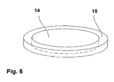
- the spindle part 10 has the actual spindle 14.
- On the spindle 14 are Workpieces clamped by suitable, known workpiece clamping systems. Also can the spindle 14 with a quick-release cylinder for clamping Replacement pallets be equipped.
- the spindle 14 itself is approximately in cross section T-shaped, namely with a face plate 15 and a bearing pin 16th With the bearing pin 16, the spindle 14 via a radial bearing 17 is rotatable in one Flange housing 18 rotatably supported about the longitudinal central axis 13.
- To the Bearing pin 16 is on the face plate 15 facing away from a ring pin 19 formed, which forms a piston surface 20 with its free end face.
- the Function of the piston surface 20 will be described below in more detail.
- the Hirthring 27 is non-rotatably connected to the spindle 14.
- a corresponding herding ring 28 is attached to the flange housing 18.
- the Hirthringe 27 and 28 are located due to the bias of the compression spring 26 into engagement with each other.
- Hydraulic or pneumatic pressure on the ring pin 19 the spindle 14 against the force of the compression spring 26 in the illustration of FIG. 1 to 6 to the right pressed and so the Hirthringe 27, 28 disengaged ( Figures 3, 4 and 6).
- the drive part 11 and 12 can now be the spindle to a freely selectable Turn angle around its longitudinal central axis 13.
- the hydraulic or Pneumatic pressure lowered again and so by the compression spring 26 the Hirthringe 27, 28 brought back into engagement.
- the spindle 14 is now in the Preselected angular position secured by the Hirth rings 27, 28 positive fit.
- spindle part 10 can be different Flange drive parts.
- Fig. 2 to 4 is an example of a drive member 11 as integrated rotary actuator shown.
- the drive part 11 has a housing 29 in, in which a bidirectionally fluid-actuated swing piston 30 in Direction of the longitudinal central axis 13 is reciprocably mounted.
- a bidirectionally fluid-actuated swing piston 30 in Direction of the longitudinal central axis 13 is reciprocably mounted.
- the Swivel piston 30 has a spiral groove 32, in the non-rotatable housing 29th mounted balls 33 engage, as this of swing clamps, for example according to DE 32 01 013 A1, is known.
- the balls 32 slide in the spiral groove 31, while the swing piston 30 is reciprocated. This will be the Swivel piston 30 relative to the stationary housing 29 is rotated.
- the balls 33 may also cooperate with spiral grooves. These Spiral grooves are then formed so that they first have a longitudinal section have, and in the length or slightly longer from it for the disengagement of the Spindle part is required. Then they go into real spiral grooves, and indeed with a direction opposite to the spiral grooves 31 for the balls 32 sense, so that a larger angle of rotation for the Panemia 15 at the same piston stroke of the Swivel piston 30 results.
- a release piston 35 is mounted, in the present case by means of Compression springs 36 is biased.
- the space for the compression springs 36 forms simultaneously a pressure chamber.
- This movement is transmitted via an axial needle bearing 37 on the pressure plate 23 and from there to the ring pin 19.
- the herds of ears 27, 28 are disengaged and disengaged (FIG. 3).
- FIGS. 5 and 6 In the embodiment of FIGS. 5 and 6 is in a housing 38 a Swivel shaft 39 rotatably supported about the longitudinal central axis 13.
- the pivot shaft 39 is non-rotatably connected to a worm wheel 40, which with a Snail 41 combs.
- a worm wheel 40 which with a Snail 41 combs.
- the spindle part 11 is pressure-medium-actuated.
- a mechanical actuation For example, via a pressure fork or the like into consideration.
Landscapes
- Engineering & Computer Science (AREA)
- Mechanical Engineering (AREA)
- Machine Tool Units (AREA)
- Cleaning By Liquid Or Steam (AREA)
- Centrifugal Separators (AREA)
- Electrical Discharge Machining, Electrochemical Machining, And Combined Machining (AREA)
- Constituent Portions Of Griding Lathes, Driving, Sensing And Control (AREA)
- Gripping On Spindles (AREA)
Abstract
Description
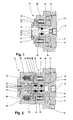
- Fig. 1
- ein Spindelteil einer Vorrichtung mit den Erfindungsmerkmalen im Längsschnitt,
- Fig. 2
- ein erstes Ausführungsbeispiel einer Vorrichtung mit einem Spindelteil gemäß Fig. 1 mit integriertem Schwenkantrieb im Längsschnitt im eingerückten Zustand,
- Fig. 3
- die Vorrichtung gemäß Fig. 2 im Längsschnitt im ausgerückten Zustand,
- Fig. 4
- die Vorrichtung gemäß Fig. 2 im Längsschnitt im ausgerückten und geschwenktem Zustand,
- Fig. 5
- ein weiteres Ausführungsbeispiel einer Vorrichtung mit einem Spindelantrieb gemäß Fig. 1 im Längsschnitt im eingerückten Zustand,
- Fig. 6
- die Vorrichtung gemäß Fig. 5 im Längsschnitt im ausgerückten Zustand.
- 10
- Spindelteil
- 11
- Antriebsteil
- 12
- Antriebsteil
- 13
- Längsmittelachse
- 14
- Spindel
- 15
- Planscheibe
- 16
- Lagerzapfen
- 17
- Radiallager
- 18
- Flanschgehäuse
- 19
- Ringzapfen
- 20
- Kolbenfläche
- 21
- Distanzscheibe
- 22
- Seegerring
- 23
- Druckscheibe
- 24
- Axialwälzkörper
- 25
- Druckscheibe
- 26
- Druckfeder
- 27
- Hirthring
- 28
- Hirthring
- 29
- Gehäuse
- 30
- Schwenkkolben
- 31
- Kugel
- 32
- Spiralnut
- 33
- Kugel
- 34
- Kugelkäfig
- 35
- Ausrückkolben
- 36
- Druckfeder
- 37
- Axialnadellager
- 38
- Gehäuse
- 39
- Schwenkwelle
- 40
- Schneckenrad
- 41
- Schnecke
- 42
- Längsnut
Claims (10)
- Vorrichtung zum Schwenken von Werkstücken oder Vorrichtungen in Bearbeitungsmaschinen mit einem Spindelteil (10), welcher ein Gehäuse (18) und eine um ihre Längsachse (13) drehbar in dem Gehäuse (18) gelagerte Spindel (14) aufweist, wobei die Spindel (14) in ihrer jeweiligen Winkellage gegenüber dem Gehäuse (18) formschlüssig sicherbar ist, dadurch gekennzeichnet, daß die formschlüssige Sicherung mittels Hirthringen (27, 28) erfolgt.
- Vorrichtung nach Anspruch 1, dadurch gekennzeichnet, daß die Spindel (14) zum Auskuppeln der Hirthringe (27, 28) gegen die Kraft wenigstens eins elastischen Elementes, insbesondere einer Feder (26), aus dem Gehäuse (18) wenigstens um das zum Auskuppeln erforderliche Maß, insbesondere druckmittelbetätigt, aushebbar ist.
- Vorrichtung nach Anspruch 2, dadurch gekennzeichnet, daß das wenigstens eine elastische Element eine Druckfeder (26) ist.
- Vorrichtung nach Anspruch 2 oder 3, dadurch gekennzeichnet, daß mehrere, insbesondere äquidistant, in Umfangsrichtung verteilte elastische Elemente vorgesehen sind.
- Vorrichtung nach einem der Ansprüche 1 bis 4, dadurch gekennzeichnet, daß der Spindelteil (10) mit einem Antriebsteil (11), mittels dessen die Spindel (14) um ihre Längsachse (13) drehend antreibbar ist, verbunden ist.
- Vorrichtung nach Anspruch 5, dadurch gekennzeichnet, daß das die Spindel (14) und ein Antriebselement (30, 39) des Antriebsteils (11), insbesondere formschlüssig, kuppelbar ist.
- Vorrichtung nach Anspruch 6, dadurch gekennzeichnet, daß die Spindel (14) und das Antriebselement (30, 39) mittels Kugeln (33) formschlüssig kuppelbar sind, insbesondere derart, daß im Antriebselement (30, 39) Längsnuten (42) vorgesehen sind, welche mit den Kugeln (33) zusammenwirken.
- Vorrichtung nach einem der Ansprüche 6 bis 7, dadurch gekennzeichnet, daß das Antriebselement ein Schwenkkolben (30) ist, der an seiner Umfangsfläche eine Spiralnut (32) aufweist, welche mit Kugeln (31) am Gehäuse (29) des Antriebsteils (11) zusammenwirkt, derart, daß durch relative Axialbewegung des Schwenkkolbens (30) gegenüber dem Gehäuse (29) eine Drehbewegung des Schwenkkolbens (30) um seine Längsachse (13) ausgeübt wird.
- Vorrichtung nach einem der Ansprüche 6 bis 7, dadurch gekennzeichnet, daß das Antriebselement eine Schwenkwelle (39) ist, welche durch ein gesondertes Antriebsmittel, insbesondere ein Schneckenrad (40) mit Schnecke (41) oder ein Zahnrad mit Zahnstange, betätigt wird.
- Anordnung von Vorrichtungen nach einem der Ansprüche 1 bis 9, dadurch gekennzeichnet, daß mehrere Vorrichtungen miteinander gekuppelt sind, derart, daß ein synchrones Schwenken der Spindelteile (10) erfolgt.
Applications Claiming Priority (2)
| Application Number | Priority Date | Filing Date | Title |
|---|---|---|---|
| DE102004002859 | 2004-01-19 | ||
| DE102004002859A DE102004002859A1 (de) | 2004-01-19 | 2004-01-19 | Vorrichtung zum Schwenken von Werkstücken oder Vorrichtung in Bearbeitungsmaschinen |
Publications (2)
| Publication Number | Publication Date |
|---|---|
| EP1555087A1 true EP1555087A1 (de) | 2005-07-20 |
| EP1555087B1 EP1555087B1 (de) | 2007-06-20 |
Family
ID=34609613
Family Applications (1)
| Application Number | Title | Priority Date | Filing Date |
|---|---|---|---|
| EP05100303A Expired - Lifetime EP1555087B1 (de) | 2004-01-19 | 2005-01-19 | Vorrichtung zum Schwenken von Werkstücken oder Vorrichtungen in Bearbeitungsmaschinen |
Country Status (3)
| Country | Link |
|---|---|
| EP (1) | EP1555087B1 (de) |
| AT (1) | ATE365093T1 (de) |
| DE (2) | DE102004002859A1 (de) |
Cited By (1)
| Publication number | Priority date | Publication date | Assignee | Title |
|---|---|---|---|---|
| CN105710720A (zh) * | 2016-04-01 | 2016-06-29 | 中航飞机股份有限公司西安飞机分公司 | 一种六方结构的铣切夹具及使用方法 |
Citations (6)
| Publication number | Priority date | Publication date | Assignee | Title |
|---|---|---|---|---|
| GB2111873A (en) * | 1981-10-26 | 1983-07-13 | Davis Gage And Engineering Com | Rotary index table with fluid pressure preloaded bearings |
| DE4124228A1 (de) * | 1991-07-22 | 1993-01-28 | Robert Ellenberger Fertigungst | Werkstueckhalter fuer werkzeugmaschinen |
| US5735180A (en) * | 1994-06-01 | 1998-04-07 | Renishaw Plc | Indexing mechanism |
| US5910201A (en) * | 1997-09-09 | 1999-06-08 | Dover Industries, Inc. | Multiple spindle screw machine |
| DE19911390A1 (de) * | 1998-03-14 | 1999-09-16 | Renishaw Plc | Schaltmechanismus |
| DE10013975A1 (de) * | 2000-03-21 | 2001-10-04 | Hohenstein Vorrichtungsbau | Adaptives Werkstück-Spann- und Handlingssystem |
-
2004
- 2004-01-19 DE DE102004002859A patent/DE102004002859A1/de not_active Withdrawn
-
2005
- 2005-01-19 DE DE502005000879T patent/DE502005000879D1/de not_active Expired - Fee Related
- 2005-01-19 AT AT05100303T patent/ATE365093T1/de not_active IP Right Cessation
- 2005-01-19 EP EP05100303A patent/EP1555087B1/de not_active Expired - Lifetime
Patent Citations (6)
| Publication number | Priority date | Publication date | Assignee | Title |
|---|---|---|---|---|
| GB2111873A (en) * | 1981-10-26 | 1983-07-13 | Davis Gage And Engineering Com | Rotary index table with fluid pressure preloaded bearings |
| DE4124228A1 (de) * | 1991-07-22 | 1993-01-28 | Robert Ellenberger Fertigungst | Werkstueckhalter fuer werkzeugmaschinen |
| US5735180A (en) * | 1994-06-01 | 1998-04-07 | Renishaw Plc | Indexing mechanism |
| US5910201A (en) * | 1997-09-09 | 1999-06-08 | Dover Industries, Inc. | Multiple spindle screw machine |
| DE19911390A1 (de) * | 1998-03-14 | 1999-09-16 | Renishaw Plc | Schaltmechanismus |
| DE10013975A1 (de) * | 2000-03-21 | 2001-10-04 | Hohenstein Vorrichtungsbau | Adaptives Werkstück-Spann- und Handlingssystem |
Cited By (1)
| Publication number | Priority date | Publication date | Assignee | Title |
|---|---|---|---|---|
| CN105710720A (zh) * | 2016-04-01 | 2016-06-29 | 中航飞机股份有限公司西安飞机分公司 | 一种六方结构的铣切夹具及使用方法 |
Also Published As
| Publication number | Publication date |
|---|---|
| EP1555087B1 (de) | 2007-06-20 |
| ATE365093T1 (de) | 2007-07-15 |
| DE502005000879D1 (de) | 2007-08-02 |
| DE102004002859A1 (de) | 2005-08-18 |
Similar Documents
| Publication | Publication Date | Title |
|---|---|---|
| DE2909227C2 (de) | ||
| DE10044915A1 (de) | Spannvorrichtung, insbesondere für mehrseitig zu bearbeitende Werkstücke | |
| DE2902421C2 (de) | ||
| DE102011082501A1 (de) | Werkstück-Positioniereinrichtung für eine Werkzeugmaschine und Werkzeugmaschine mit einer derartigen Werkstück-Positioniereinrichtung | |
| DE69521726T2 (de) | Schleifmaschine und Verfahren zum Schleifen von Kurbelwellenzapfen | |
| DE10160705A1 (de) | Vorrichtung zur Befestigung eines Werkzeugs an einer Welle sowie Maschinenspindel mit einer derartigen Vorrichtung | |
| DE3630966A1 (de) | Drehmaschinen-werkzeugrevolver | |
| DE2758858A1 (de) | Werkzeugmaschine | |
| DE4020579C2 (de) | ||
| DE3619145C1 (de) | Spannfutter mit zwei gegenueberliegenden Spannbacken | |
| EP2167265A1 (de) | Bruchtrennmodul für eine werkzeugmaschine, werkzeugmaschine mit einem bruchtrennmodul und verfahren zum bruchtrennen | |
| EP1555087B1 (de) | Vorrichtung zum Schwenken von Werkstücken oder Vorrichtungen in Bearbeitungsmaschinen | |
| DE3013957C2 (de) | Gesenk-Auswechselvorrichtung | |
| EP0324978B1 (de) | Walzwerksantrieb mit zwischen Kammwalzen und Arbeitswalzen lösbar angeordneten Gelenkspindeln | |
| EP0539667B1 (de) | Werkzeugrevolver | |
| EP1011915A1 (de) | Antriebsvorrichtung für mehrere aggregate einer maschine | |
| DE20204741U1 (de) | Vorrichtung zum Zurücksetzen eines Bremskolbens | |
| DE4432084C2 (de) | Verfahren und Werkzeug zum Aus- und Einbauen eines Walzringes | |
| EP3670046A1 (de) | Mitnehmereinrichtung | |
| DE2622744A1 (de) | Einrichtung zur zahnspieleinstellung in pneumatisch oder hydraulisch betriebenen schwenkmotoren | |
| DE2004715A1 (de) | Drehbare Einspannvorrichtung | |
| DE19830629C2 (de) | Werkzeugsternrevolver | |
| DE3716313A1 (de) | Ueberlastkupplung fuer einen gewindeschneider | |
| DE20003730U1 (de) | Spanneinrichtung zur Fixierung eines Einzugsbolzens | |
| DE3034009C2 (de) | Vorrichtung zur Verstellung des Stößelhubes bei Doppelständerpressen mit zwei nebeneinander liegenden Exzenterwellen |
Legal Events
| Date | Code | Title | Description |
|---|---|---|---|
| PUAI | Public reference made under article 153(3) epc to a published international application that has entered the european phase |
Free format text: ORIGINAL CODE: 0009012 |
|
| AK | Designated contracting states |
Kind code of ref document: A1 Designated state(s): AT BE BG CH CY CZ DE DK EE ES FI FR GB GR HU IE IS IT LI LT LU MC NL PL PT RO SE SI SK TR |
|
| AX | Request for extension of the european patent |
Extension state: AL BA HR LV MK YU |
|
| 17P | Request for examination filed |
Effective date: 20060120 |
|
| AKX | Designation fees paid |
Designated state(s): AT BE BG CH CY CZ DE DK EE ES FI FR GB GR HU IE IS IT LI LT LU MC NL PL PT RO SE SI SK TR |
|
| 17Q | First examination report despatched |
Effective date: 20060720 |
|
| GRAP | Despatch of communication of intention to grant a patent |
Free format text: ORIGINAL CODE: EPIDOSNIGR1 |
|
| RIN1 | Information on inventor provided before grant (corrected) |
Inventor name: MATZAT, HENDRIC Inventor name: EHRHARDT, WINFRIED |
|
| GRAS | Grant fee paid |
Free format text: ORIGINAL CODE: EPIDOSNIGR3 |
|
| GRAA | (expected) grant |
Free format text: ORIGINAL CODE: 0009210 |
|
| AK | Designated contracting states |
Kind code of ref document: B1 Designated state(s): AT BE BG CH CY CZ DE DK EE ES FI FR GB GR HU IE IS IT LI LT LU MC NL PL PT RO SE SI SK TR |
|
| REG | Reference to a national code |
Ref country code: GB Ref legal event code: FG4D Free format text: NOT ENGLISH |
|
| REG | Reference to a national code |
Ref country code: CH Ref legal event code: EP |
|
| REG | Reference to a national code |
Ref country code: IE Ref legal event code: FG4D Free format text: LANGUAGE OF EP DOCUMENT: GERMAN |
|
| REF | Corresponds to: |
Ref document number: 502005000879 Country of ref document: DE Date of ref document: 20070802 Kind code of ref document: P |
|
| PG25 | Lapsed in a contracting state [announced via postgrant information from national office to epo] |
Ref country code: SE Free format text: LAPSE BECAUSE OF FAILURE TO SUBMIT A TRANSLATION OF THE DESCRIPTION OR TO PAY THE FEE WITHIN THE PRESCRIBED TIME-LIMIT Effective date: 20070920 |
|
| PG25 | Lapsed in a contracting state [announced via postgrant information from national office to epo] |
Ref country code: PL Free format text: LAPSE BECAUSE OF FAILURE TO SUBMIT A TRANSLATION OF THE DESCRIPTION OR TO PAY THE FEE WITHIN THE PRESCRIBED TIME-LIMIT Effective date: 20070620 |
|
| NLV1 | Nl: lapsed or annulled due to failure to fulfill the requirements of art. 29p and 29m of the patents act | ||
| GBV | Gb: ep patent (uk) treated as always having been void in accordance with gb section 77(7)/1977 [no translation filed] |
Effective date: 20070620 |
|
| REG | Reference to a national code |
Ref country code: IE Ref legal event code: FD4D |
|
| PG25 | Lapsed in a contracting state [announced via postgrant information from national office to epo] |
Ref country code: NL Free format text: LAPSE BECAUSE OF FAILURE TO SUBMIT A TRANSLATION OF THE DESCRIPTION OR TO PAY THE FEE WITHIN THE PRESCRIBED TIME-LIMIT Effective date: 20070620 Ref country code: BG Free format text: LAPSE BECAUSE OF FAILURE TO SUBMIT A TRANSLATION OF THE DESCRIPTION OR TO PAY THE FEE WITHIN THE PRESCRIBED TIME-LIMIT Effective date: 20070920 Ref country code: IE Free format text: LAPSE BECAUSE OF FAILURE TO SUBMIT A TRANSLATION OF THE DESCRIPTION OR TO PAY THE FEE WITHIN THE PRESCRIBED TIME-LIMIT Effective date: 20070620 Ref country code: IS Free format text: LAPSE BECAUSE OF FAILURE TO SUBMIT A TRANSLATION OF THE DESCRIPTION OR TO PAY THE FEE WITHIN THE PRESCRIBED TIME-LIMIT Effective date: 20071020 Ref country code: CZ Free format text: LAPSE BECAUSE OF FAILURE TO SUBMIT A TRANSLATION OF THE DESCRIPTION OR TO PAY THE FEE WITHIN THE PRESCRIBED TIME-LIMIT Effective date: 20070620 Ref country code: ES Free format text: LAPSE BECAUSE OF FAILURE TO SUBMIT A TRANSLATION OF THE DESCRIPTION OR TO PAY THE FEE WITHIN THE PRESCRIBED TIME-LIMIT Effective date: 20071001 Ref country code: SI Free format text: LAPSE BECAUSE OF FAILURE TO SUBMIT A TRANSLATION OF THE DESCRIPTION OR TO PAY THE FEE WITHIN THE PRESCRIBED TIME-LIMIT Effective date: 20070620 Ref country code: PT Free format text: LAPSE BECAUSE OF FAILURE TO SUBMIT A TRANSLATION OF THE DESCRIPTION OR TO PAY THE FEE WITHIN THE PRESCRIBED TIME-LIMIT Effective date: 20071120 |
|
| EN | Fr: translation not filed | ||
| PG25 | Lapsed in a contracting state [announced via postgrant information from national office to epo] |
Ref country code: LT Free format text: LAPSE BECAUSE OF FAILURE TO SUBMIT A TRANSLATION OF THE DESCRIPTION OR TO PAY THE FEE WITHIN THE PRESCRIBED TIME-LIMIT Effective date: 20070620 Ref country code: SK Free format text: LAPSE BECAUSE OF FAILURE TO SUBMIT A TRANSLATION OF THE DESCRIPTION OR TO PAY THE FEE WITHIN THE PRESCRIBED TIME-LIMIT Effective date: 20070620 |
|
| PLBE | No opposition filed within time limit |
Free format text: ORIGINAL CODE: 0009261 |
|
| STAA | Information on the status of an ep patent application or granted ep patent |
Free format text: STATUS: NO OPPOSITION FILED WITHIN TIME LIMIT |
|
| PG25 | Lapsed in a contracting state [announced via postgrant information from national office to epo] |
Ref country code: IT Free format text: LAPSE BECAUSE OF FAILURE TO SUBMIT A TRANSLATION OF THE DESCRIPTION OR TO PAY THE FEE WITHIN THE PRESCRIBED TIME-LIMIT Effective date: 20070620 Ref country code: DK Free format text: LAPSE BECAUSE OF FAILURE TO SUBMIT A TRANSLATION OF THE DESCRIPTION OR TO PAY THE FEE WITHIN THE PRESCRIBED TIME-LIMIT Effective date: 20070620 Ref country code: GB Free format text: LAPSE BECAUSE OF FAILURE TO SUBMIT A TRANSLATION OF THE DESCRIPTION OR TO PAY THE FEE WITHIN THE PRESCRIBED TIME-LIMIT Effective date: 20070620 Ref country code: GR Free format text: LAPSE BECAUSE OF FAILURE TO SUBMIT A TRANSLATION OF THE DESCRIPTION OR TO PAY THE FEE WITHIN THE PRESCRIBED TIME-LIMIT Effective date: 20070921 |
|
| 26N | No opposition filed |
Effective date: 20080325 |
|
| PG25 | Lapsed in a contracting state [announced via postgrant information from national office to epo] |
Ref country code: RO Free format text: LAPSE BECAUSE OF FAILURE TO SUBMIT A TRANSLATION OF THE DESCRIPTION OR TO PAY THE FEE WITHIN THE PRESCRIBED TIME-LIMIT Effective date: 20070620 |
|
| PGFP | Annual fee paid to national office [announced via postgrant information from national office to epo] |
Ref country code: DE Payment date: 20080131 Year of fee payment: 4 |
|
| BERE | Be: lapsed |
Owner name: LUDWIG EHRHARDT G.M.B.H. Effective date: 20080131 |
|
| PG25 | Lapsed in a contracting state [announced via postgrant information from national office to epo] |
Ref country code: FR Free format text: LAPSE BECAUSE OF FAILURE TO SUBMIT A TRANSLATION OF THE DESCRIPTION OR TO PAY THE FEE WITHIN THE PRESCRIBED TIME-LIMIT Effective date: 20080222 |
|
| PG25 | Lapsed in a contracting state [announced via postgrant information from national office to epo] |
Ref country code: MC Free format text: LAPSE BECAUSE OF NON-PAYMENT OF DUE FEES Effective date: 20080131 |
|
| PG25 | Lapsed in a contracting state [announced via postgrant information from national office to epo] |
Ref country code: EE Free format text: LAPSE BECAUSE OF FAILURE TO SUBMIT A TRANSLATION OF THE DESCRIPTION OR TO PAY THE FEE WITHIN THE PRESCRIBED TIME-LIMIT Effective date: 20070620 |
|
| PG25 | Lapsed in a contracting state [announced via postgrant information from national office to epo] |
Ref country code: FI Free format text: LAPSE BECAUSE OF FAILURE TO SUBMIT A TRANSLATION OF THE DESCRIPTION OR TO PAY THE FEE WITHIN THE PRESCRIBED TIME-LIMIT Effective date: 20070620 Ref country code: BE Free format text: LAPSE BECAUSE OF NON-PAYMENT OF DUE FEES Effective date: 20080131 |
|
| PG25 | Lapsed in a contracting state [announced via postgrant information from national office to epo] |
Ref country code: AT Free format text: LAPSE BECAUSE OF NON-PAYMENT OF DUE FEES Effective date: 20080119 |
|
| PGFP | Annual fee paid to national office [announced via postgrant information from national office to epo] |
Ref country code: CH Payment date: 20090126 Year of fee payment: 5 |
|
| PG25 | Lapsed in a contracting state [announced via postgrant information from national office to epo] |
Ref country code: CY Free format text: LAPSE BECAUSE OF FAILURE TO SUBMIT A TRANSLATION OF THE DESCRIPTION OR TO PAY THE FEE WITHIN THE PRESCRIBED TIME-LIMIT Effective date: 20070620 |
|
| PG25 | Lapsed in a contracting state [announced via postgrant information from national office to epo] |
Ref country code: DE Free format text: LAPSE BECAUSE OF NON-PAYMENT OF DUE FEES Effective date: 20090801 |
|
| PG25 | Lapsed in a contracting state [announced via postgrant information from national office to epo] |
Ref country code: HU Free format text: LAPSE BECAUSE OF FAILURE TO SUBMIT A TRANSLATION OF THE DESCRIPTION OR TO PAY THE FEE WITHIN THE PRESCRIBED TIME-LIMIT Effective date: 20071221 Ref country code: LU Free format text: LAPSE BECAUSE OF NON-PAYMENT OF DUE FEES Effective date: 20080119 |
|
| PG25 | Lapsed in a contracting state [announced via postgrant information from national office to epo] |
Ref country code: TR Free format text: LAPSE BECAUSE OF FAILURE TO SUBMIT A TRANSLATION OF THE DESCRIPTION OR TO PAY THE FEE WITHIN THE PRESCRIBED TIME-LIMIT Effective date: 20070620 |
|
| REG | Reference to a national code |
Ref country code: CH Ref legal event code: PL |
|
| PG25 | Lapsed in a contracting state [announced via postgrant information from national office to epo] |
Ref country code: LI Free format text: LAPSE BECAUSE OF NON-PAYMENT OF DUE FEES Effective date: 20100131 Ref country code: CH Free format text: LAPSE BECAUSE OF NON-PAYMENT OF DUE FEES Effective date: 20100131 |