EP1554431B1 - Dampf wasser sprühsystem - Google Patents
Dampf wasser sprühsystem Download PDFInfo
- Publication number
- EP1554431B1 EP1554431B1 EP03769390A EP03769390A EP1554431B1 EP 1554431 B1 EP1554431 B1 EP 1554431B1 EP 03769390 A EP03769390 A EP 03769390A EP 03769390 A EP03769390 A EP 03769390A EP 1554431 B1 EP1554431 B1 EP 1554431B1
- Authority
- EP
- European Patent Office
- Prior art keywords
- nozzle
- steam
- steam stream
- stream
- flow
- Prior art date
- Legal status (The legal status is an assumption and is not a legal conclusion. Google has not performed a legal analysis and makes no representation as to the accuracy of the status listed.)
- Expired - Fee Related
Links
- XLYOFNOQVPJJNP-UHFFFAOYSA-N water Substances O XLYOFNOQVPJJNP-UHFFFAOYSA-N 0.000 title claims description 103
- 239000007921 spray Substances 0.000 title description 28
- 239000007788 liquid Substances 0.000 claims description 23
- 238000000034 method Methods 0.000 claims description 16
- 239000000463 material Substances 0.000 claims description 8
- 238000010438 heat treatment Methods 0.000 claims description 4
- 238000009736 wetting Methods 0.000 claims description 4
- 238000007599 discharging Methods 0.000 claims 4
- 238000011144 upstream manufacturing Methods 0.000 description 14
- 230000008901 benefit Effects 0.000 description 11
- 238000002156 mixing Methods 0.000 description 11
- 238000004519 manufacturing process Methods 0.000 description 9
- 238000013461 design Methods 0.000 description 7
- 239000002245 particle Substances 0.000 description 7
- 239000000203 mixture Substances 0.000 description 6
- 230000001105 regulatory effect Effects 0.000 description 6
- 238000009530 blood pressure measurement Methods 0.000 description 5
- 238000004891 communication Methods 0.000 description 5
- 238000009826 distribution Methods 0.000 description 5
- 230000000694 effects Effects 0.000 description 5
- 239000000835 fiber Substances 0.000 description 4
- 239000012530 fluid Substances 0.000 description 4
- 230000006872 improvement Effects 0.000 description 4
- 239000002184 metal Substances 0.000 description 4
- 238000012544 monitoring process Methods 0.000 description 4
- 238000009833 condensation Methods 0.000 description 3
- 230000005494 condensation Effects 0.000 description 3
- 238000003490 calendering Methods 0.000 description 2
- 230000008859 change Effects 0.000 description 2
- 230000007246 mechanism Effects 0.000 description 2
- 238000003825 pressing Methods 0.000 description 2
- 230000008569 process Effects 0.000 description 2
- 230000009467 reduction Effects 0.000 description 2
- 238000010008 shearing Methods 0.000 description 2
- 239000002002 slurry Substances 0.000 description 2
- 230000009471 action Effects 0.000 description 1
- 238000007792 addition Methods 0.000 description 1
- 230000006835 compression Effects 0.000 description 1
- 238000007906 compression Methods 0.000 description 1
- 230000001276 controlling effect Effects 0.000 description 1
- 238000012217 deletion Methods 0.000 description 1
- 230000037430 deletion Effects 0.000 description 1
- 238000003745 diagnosis Methods 0.000 description 1
- 238000001704 evaporation Methods 0.000 description 1
- 230000005484 gravity Effects 0.000 description 1
- 238000012986 modification Methods 0.000 description 1
- 230000004048 modification Effects 0.000 description 1
- 238000002360 preparation method Methods 0.000 description 1
- 239000007787 solid Substances 0.000 description 1
- 238000005507 spraying Methods 0.000 description 1
Images


Classifications
-
- D—TEXTILES; PAPER
- D21—PAPER-MAKING; PRODUCTION OF CELLULOSE
- D21G—CALENDERS; ACCESSORIES FOR PAPER-MAKING MACHINES
- D21G7/00—Damping devices
-
- D—TEXTILES; PAPER
- D21—PAPER-MAKING; PRODUCTION OF CELLULOSE
- D21F—PAPER-MAKING MACHINES; METHODS OF PRODUCING PAPER THEREON
- D21F7/00—Other details of machines for making continuous webs of paper
- D21F7/008—Steam showers
Definitions
- This invention relates to a method and apparatus to deliver both heat and moisture to a web of paper and more particularly to a method and apparatus for atomizing water with steam to improve the production and paper qualities of a papermaking machine.
- a continuous fiber/water slurry is formed as a moving web on a paper machine. As the slurry moves down the paper machine the water is removed to leave the fiber which forms the paper sheet.
- the paper machine has several sections.
- the first section drains the water under the influences of gravity and vacuum on the Fourdrinier table. After the Fourdrinier table a web is produced with sufficient strength to be self-supporting to feed itself into a second or press section.
- the second section of the paper machine presses the paper web and squeezes the water from the sheet.
- This section typically consists of a series of rolls forming press nips through which the paper web is fed. After pressing removes all the water that it can, the remaining moisture in the web must be evaporated.
- the third section of the paper machine normally referred to as the dryer, evaporates the remaining moisture in the paper web down to the final level desired for the grade of paper being produced.
- a calender that adds gloss and smoothness to the paper surface. If the paper surface requires higher gloss and smoothness than that which can be achieved by the normal on-machine calendering then off-machine supercalendering is further applied to the paper surface.
- the moisture profile in the cross-machine direction is one of many important qualities of paper products. It is not only important that the overall moisture level be controlled, but also that the moisture distribution throughout the sheet be controlled both in the direction that the sheet is moving known as the machine direction (MD) and in the CD. Variation in moisture content of the sheet will often affect paper quality as much or even more than the absolute moisture content.
- Steam showers are conventional profiling systems that work by selectively delivering steam onto the paper web during production.
- Profiling steam showers deliver a variable distribution of steam in zones across the paper web. The amount of steam passing through each zone of a steam shower is adjusted through an actuator located in that zone.
- Steam showers are widely used on the Fourdrinier table to help drainage and increase production.
- steam is added before the press nips to increase the temperature of the web.
- the added temperature makes the water removal by pressing much more effective as the added moisture removal is much greater than the added moisture due to steam condensation.
- Profiling steam showers are also used in the calendering process to improve gloss and smoothness of the paper products.
- Moisture spray systems are also conventional profiling systems normally used in the evaporating sections of paper machines.
- the water spray systems are designed to apply a profile of moisture spray in the cross-machine direction to counter an undesirable moisture profile in the paper web.
- These systems consist of a series of flow-controlling actuators capable of independently adjusting the amount of spray in discrete adjacent zones in the CD.
- the nozzle is the device that breaks the water particles into fine droplets. These nozzles typically use a separate air pressure line to produce the droplets.
- Steam showers basically add moisture and heat to the web by impinging hot steam on to the surface of paper.
- the latent energy in the steam is released when steam condensation occurs on the paper surface, and causes the web temperature to rise. Steam condensation continues until a certain temperature on the paper surface is reached.
- Higher web temperature implies less viscosity of the moisture, and consequently less resistance to the dewatering of the press section. It is the added heat that contributes to the improvement of machine runnability and efficiency, and consequently to the increase of the paper production.
- Profiling steam showers are also used to improve moisture content in the web.
- the resulting benefits are limited due to the capability of the paper sheet to condense steam on to its surface.
- steam will not condense on the paper surface if the surface temperature is too high, instead it bounces back into the environment and is wasted.
- Water spray systems directly add moisture to the paper surface to improve the moisture profile. Before spraying water to the web, the water is normally heated to the temperature of the web to prevent any by-effects due to the temperature disturbance. Compared to steam shower systems, water spray systems have more freedom for moisture manipulation. However the water spray systems have limited effects on the temperature rise of the web. Therefore, water sprays are generally used for quality improvements while steam showers are used for improving both production and quality.
- Patent document DE2925026 discloses a method and apparatus for moistening fiber webs, in particular paper webs, wherein water is added to the steam as it exits a nozzle and the mixture of water and steam is sprayed into a high voltage electrostatic filed positioned over the fiber web.
- patent document US 4,946,101 describes an atomizing apparatus which has a first nozzle receiving air and a second nozzle which receives a flow of liquid. The air stream is divided into two streams, one of which is swirled and breaks up the adjacent layer of the liquid flow into minute droplets so that such layer is converted into a finely atomized flow of liquid particles. The remaining portion of the air stream which is not converted into the swirling stream is caused to flow in an axial direction of the swirled stream. Then, a web of paper is wetted by a flow of atomized liquid which is formed by the both streams.
- the apparatus and method of the present invention was developed in order to overcome the shortcomings of both steam showers and water spray systems.
- the present invention combines the advantages of steam showers with that of water spray systems.
- the method involves impinging a predetermined mixture of steam and spray on to the web for both production and quality improvement.
- the predetermined mixture contains carefully calculated moisture and heat for a specific application without the limits arising from only a steam shower or only a water spray.
- the novel apparatus involves using existing actuator nozzle modules that are able to use steam to break water into fine droplets.
- the actuator controls the moisture content in the mixture.
- the heat of the mixture can be controlled by adjusting the steam pressure and the amount of superheating of the steam.
- actuators there are two types that can be used in the apparatus of the present invention.
- One converts a control signal to a linear movement.
- the linear movement is then employed to adjust proportionally an opening area in a valve mechanism.
- the flow amount passing through this valve is therefore controllable in a linear fashion by keeping the upstream flow pressure constant, and the varying opening area at the valve determines the flow rate.
- the other actuator type is referred to as the regulator type.
- the regulator-type actuator regulates the flow pressure feeding a constant opening based on a controlling reference pneumatic pressure.
- the varying pressure feeding the constant orifice determines the flow rate.
- the regulator-type actuator is especially effective for applications requiring small flow control. It can be appreciated that precisely adjusting the opening of a small orifice is very difficult. Thus it is much easier to keep the opening of the small orifice untouched while regulating the flow pressure feeding that orifice. Another advantage of the regulator type actuator is its capability to fully close the valve when needed. Therefore the regulator-type actuator is used for the novel apparatus of the present invention because of its superior performance.
- a method of wetting and heating webs of paper or other hygroscopic material comprises the following steps:
- An apparatus for wetting and heating webs of paper or other hygroscopic material comprising one or more nozzles, wherein each of said one or more nozzles atomizes a flow of liquid by a steam stream that is the combination of a swirling steam stream, one straight steam stream and another straight steam stream to thereby provide both moisture and steam to a web of paper of other hygroscopic material.
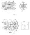
- FIG. 1 shows a segment of the preferred embodiment for the steam water spray system 1 of the present invention.
- System 1 consists of a plurality of actuator nozzle modules 10 mounted on a plate 6 across the paper web in the CD.
- a common water chamber 2 in sealed communication with a water supply unit (not shown) feeds pressurized water to each actuator nozzle module 10 through a hole (not shown) in the plate 6.
- a water return pipe 5 recycles unused water back to a water tank (not shown) of the water supply unit.
- a common steam chamber 3 in sealed communication with a steam preparation system (not shown) feeds pressurized steam to each actuator nozzle module 10 through another hole (not shown) in the plate 6.
- a remotely generated pneumatic signal of 6 PSIG to 30 PSIG sent through air tubes 4 controls the water volume flow passing through each actuator nozzle module 10.
- Module 10 consists of an atomizing nozzle 22 and a regulator-type actuator 20.
- Nozzle 22 includes a port 28 which is in sealed communication with the common water chamber 2 through the plate 6 of Figure 1 .
- the port 28 receives pressurized water from the water chamber 2 and then feeds that water to the regulator type actuator 20.
- the actuator 20 regulates the water pressure between 0 PSIG and 24 PSIG feeding a pair of orifices 12 and 14 and a water nozzle 26 downstream of the orifices.
- the feeding pressure and the sizes of the orifices 12 and 14 and the water nozzle 26 fully determine the water volume flow through the module 10.
- the pressure port 18 is located upstream of the pair of orifices 12 and 14, while the other port 16 is linked to the space between the two orifices 12 and 14.
- the pressure measurements at the two pressure ports 16 and 18 can, as will be described below, be used to monitor the status of the two orifices 12 and 14 and the water nozzle 26.
- steam is feed into a channel 70 of the atomizing nozzle 22 through a port 30 which is in sealed communication with the common steam chamber 3 through the plate 6 of Figure 1 .
- Steam in the channel 70 then splits into three streams: one stream through a circumferential gap 72 around the water nozzle 26, another stream through a flat gap 76 adjacent to the nozzle exit, and yet another stream through two off-center orifices 86.
- the separated streams then mix again in a mixing chamber 74 before emitting to the environment through an annulus 78 around the water nozzle 26.
- Steam passing through the two off-centered orifices 86 in opposite directions creates a swirling component of the mixed flow in the mixing chamber 74. This swirling component does not exist in conventional steam showers.
- valve stem 46 which is attached to a piston 44 combined with a valve seat 48 forms a valve at the source water inlet.
- the steam water spray system 1 of the present invention is superior to conventional steam showers, because of the added swirling component in the steam jet.
- the swirling movement allows the steam to easily penetrate the boundary layer formed by the air carried by the moving web. Improved contact between the steam and the paper surface increases the efficiency of the steam treatment.
- a plurality of steam valves upstream of the port 30 can be used to regulate the steam volume flow feeding the atomizing nozzle 22.
- This configuration allows, as does conventional steam showers, temperature profiling across the web in the CD.
- the added water associated with the present invention extends the range of moisture manipulation of a conventional steam shower.
- the capability of regulating steam volume flow also adds size control to droplets produced by the atomizing nozzle. As is well known, the more the atomizing fluid flow, the smaller the droplets produced by an atomizing nozzle.
- the steam atomizing of the present invention provides when compared to air atomizing benefits to the spray system.
- the large water volume flow for heavy grade paper requires more atomizing fluid flow to atomize the water.
- more atomizing flow indicates a higher atomizing pressure.
- It is much more expensive to compress air to a pressure higher than 15 PSIG because of the difference in cost between the air blower that is capable of compressing the air up to 15 PSIG and the compressor needed to compress the air to pressures higher than 15 PSIG.
- steam with a pressure higher than 15 PSIG is readily available in any paper mill.
- the regulator-type actuator 20 of Fig. 2 is described in commonly owned U.S. Patent Number 6,394,418 for "Bellows Actuator for Pressure and Flow Control”.
- Fig. 3 there is shown an embodiment for the regulator-type actuator 20.
- Actuator 20 consists of an internal chamber 32 and an external chamber 34 separated by a flexible metal bellows 36.
- the external chamber 34 is the space formed by actuator body 40, the bellows 36, the end piece 42 and the piston 44.
- the control air inlet 24 feeds into the external chamber 34.
- the internal chamber 32 is the space formed by the water inlet end piece 42, the bellows 36 and the piston 44.
- the source water inlet 50 in sealed communication with the water port 28 of Figure 2 feeds into the internal chamber 32.
- a valve stem 46 attached to the piston 44 combined with a valve seat 48 forms a valve at the source water inlet 50.
- a spray water outlet 52 directs the water to the double orifices 12 and 14 and the nozzle orifice 26 through the water inlet 62 of Figure 4 .
- Initial setup of the actuator 20 involves compressing the metal bellows 36 a predetermined amount and attaching the valve stem 46 such that the valve orifice 54 is closed at this pre-compressed setting.
- the water inlet end piece 42 and the piston 44 are designed to diametrically guide each other in their relative movement as well as act as an anti-squirm guide for the bellows 36.
- the actuator 20 works to control the pressure fed to the double orifices 12 and 14 and the nozzle orifice 26 using the pneumatic control air pressure at the port 24 as a reference.
- Source water is fed to the source water inlet 50 at a pressure in excess of the maximum desired pressure for the spray nozzle 22.
- Control air is fed to the metal bellows 36 through actuator body 40.
- the air pressure in the external chamber 34 acts against the effective area of the bellows 36 and creates an operating force, which is resisted by three opposing forces.
- the first opposing force is formed by the spring action of the pre-compressed metal bellows 36.
- the second opposing force is formed by the pressure of the source water acting against the relatively small area of the valve orifice 54 opening.
- the third opposing force is formed by the spray water pressure in the internal chamber 32 acting against the effective area of the bellows 36.
- the first two reactive forces are substantially small or constant which allows changes to the control air pressure to predictably affect the pressure of the water feeding the double orifices 12 and 14 and the nozzle orifice 26.
- the actuator 20 operates on a balance of these forces.
- valve stem 46 remains against the valve seat 48 and no water passes through the valve orifice 54.
- the double orifices 12 and 14 and nozzle orifice 26 downstream receive no water pressure to feed them.
- valve stem 46 When the control air pressure exceeds the kickoff pressure of the actuator 20, the valve stem 46 is pushed down by the piston and water flows through the valve orifice 54 into the internal chamber 32 and out to the double orifices 12 and 14 and nozzle orifice 26.
- the double orifices 12 and 14 and the nozzle orifice 26 downstream allow water flow through it but also offer resistance to such flow.
- the pressure in the internal chamber 32 builds.
- regulated water pressure between 0 PSIG and 24 PSIG, proportional to the pneumatic control pressure of between 6 PSIG and 30 PSIG.
- the regulated water pressure and the size of the double orifices 12 and 14 determine the flow rate passing through the actuator nozzle module.
- the atomizing nozzle 22 uses a combination of three air streams to break the water into small droplets and produce an appropriate moisture profile that is suitable for paper quality improvement applications.
- the nozzle portion consists of a nozzle body 56, a double orifice device 12 and 14, a water nozzle tube 58, a stream divider 82 and a steam cap 60.
- the nozzle body 56 also serves as a mounting base for the actuator 20.
- the source water inlet 28 on the nozzle body 56 is connected to the source water inlet 50 of Figure 3 to the actuator 20.
- the spray water outlet 52 from the actuator 20 of Figure 3 is aligned with the regulated water inlet 62 on the nozzle body 56. Water from the actuator 20 feeds into the water inlet 62, passing through the double orifices 12 and 14, and finally emits from the water nozzle 26.
- Atomizing steam feeds into the steam chamber 70 formed by the nozzle body 56, the water tube 58, the stream divider 82 and the steam cap 60 through the atomizing steam inlet 30.
- the atomizing steam in the steam channel 70 is then separated into three different flow streams by using the cylindrical stream divider 82 an enlargement of which is shown in Fig. 5 .
- One of the streams passing through the holes 98 (shown in Figure 5 ) drilled towards the central axis of the cylindrical stream divider 82 gets into the chamber 80 formed by the water tube 58 and the stream divider 82. This stream then flows into the gap 72 between the divider 82 and the water tube 58 before it enters the mixing chamber 74 to form the first steam stream around the water tube 58.
- Two flat surfaces 96 (shown in Figure 5 ) machined from the cylindrical outer surface of the stream divider 82 and located on one end of the divider 82.
- the two flat surfaces are located opposite to each other.
- Two steam channels 84 are formed between the two flat surfaces 96 on the stream divider 82 and the inner surface of the steam cap 60.
- the two steam channels 84 are connected to the steam channel 70. Atomizing steam in channels 84 are used for the second and the third streams.
- the second steam stream passes through the two holes 86 drilled off-center on the two flat surfaces 96 of the stream divider 82 and flows tangentially into the mixing chamber 74.
- the two off-centered holes 86 are aligned in opposite directions so that swirling flow is produced in the mixing chamber 74 around the first steam stream.
- the size of the two orifices 86 and the steam pressure in the channel 70 determine the strength of the swirl in the mixing chamber 74.
- the swirl determines the spray pattern of the final jet, especially the width of the final jet.
- the third steam stream is generated by atomizing steam in the two steam channels 84 passing through the gap 76 formed between the steam cap 60 and the steam divider 82.
- a ring 88 is used to control the width of the gap 76, and consequently the shape of the resulting spray profile.
- the third stream passes through the gap 76, bends towards the chamfered surface 90 on the steam cap 60 due to the Coanda effect.
- the Coanda effect indicates that flow tends to attach to a solid surface.
- the third stream wraps the swirling flow and the first stream within it in the mixing chamber 74. The combination of the three streams rushes out of the annulus 78 around the water jet emitting from nozzle orifice 26.
- One of the benefits is the efficiency of the atomizing nozzle.
- an area with low pressure is created near the chamfer 90 of the steam cap 60 also due to the Coanda effect.
- This low pressure in chamber 74 created by the third stream reduces the resistance on both the first steam stream and the swirling second stream. This reduction of the resistance indicates that exactly the same spray pattern (particle size and mass profile) that is created by the three air streams used in the atomizing nozzle described in the '408 Application can also be created with relatively low atomizing steam source pressure.
- Another benefit of the atomizing nozzle design is that the design allows control of the two slopes of the water mass profile generated by the nozzle.
- the third stream which is a result of the design adds axial momentum to the outer region of the swirl that steepens the two slopes on the outer edges of the profile and makes the profile closer to an ideal square in shape.
- Still yet another benefit of the nozzle design is also efficiency related.
- the swirl generated by the two off-centered holes 86 in the mixing chamber 74 is compressed in the convergent area formed by the chamfer 90 on the steam cap 60.
- the tangential velocity in the swirl increases dramatically during the compression.
- the chamfer 90 of the steam cap 60 drags the tangential velocity to zero on the chamfer surface.
- the friction on the chamfer surface dissipates the strength of the swirl and causes inefficiency in the nozzle.
- the third stream located between the swirl and the chamfer surface acts as a cushion for the swirl and preserves the vortical strength of the swirl.
- This actuator nozzle unit 10 The monitoring capability of this actuator nozzle unit 10 is achieved by pressure measurement at two pressure ports 16 and 18 of Figure 2 . As is shown in Figure 2 there is a pressure port 16 located right between the two orifices 12 and 14. There is also another pressure port 18 upstream of the two orifices 12 and 14 that monitors the regulated water pressure from the actuator 20 included in the module 10. The upstream pressure measured is compared with the pneumatic control pressure sent to the actuator 20 through port 24. This comparison results in the performance diagnosis of the actuator 20.
- the pressure measured between the two orifices 12 and 14 in combination with the pressure measured upstream can be used to monitor the status of the double orifices 12, 14 and the water orifice 26.
- Orifice monitoring is achieved by using a double orifice technique.
- the double orifice technique is based on the fact that there is always a pressure drop when a moving fluid passes an orifice.
- the pressure change at port 16 between the orifices 12 and 14 is monitored over time comparing to the upstream pressure at port 18.
- the pressure between the double orifices 12, 14 should be a portion of the upstream pressure, and the ratio of the two pressures is a constant regardless of flow conditions, if there is no geometrical variation in the flow passage.
- the measured pressure between the double orifices 12 and 14 will be lower than normal.
- a zero pressure measurement between the orifices 12 and 14 indicates full blockage at the upstream orifice 12 during normal operation.
- wearing occurs to the upstream orifice 12 increasing pressure should be expected between the double orifices 12 and 14.
- a blockage at the downstream orifice 14 or the water nozzle 26 resists the flow more and consequently a higher pressure should occur between the orifices 12 and 14.
- the downstream orifice 14 is fully blocked, the pressure between the two orifices 12 and 14 equals the upstream pressure. Downstream orifice wearing results in a pressure drop.
- a pressure drop between the orifices 12 and 14 indicates either blockage at the upstream orifice 12 or wearing downstream.
- Pressure increasing between the orifices 12 and 14 implies that there is either wearing at the upstream orifice 12 or blockage downstream.
- the nozzle orifice 26, which affects the droplet size from the nozzle 22, is the same for all applications. Orifice diameters of the double orifices 12, 14 determine the maximum water flow capacity for each individual application. For most of the applications, the nozzle orifice 26 is much larger than the flow orifice diameter. Therefore the pressure drop through the water orifice 26 is substantially less than the pressure drop through any one of the two orifices 12, 14. A relatively large pressure value at the port 16 makes precise pressure measurement there easier. That is why the monitoring technique uses two orifices 12, 14 instead of one in the design. In practice, the diameters of the two orifices 12, 14 can be either identical or different.
Landscapes
- Paper (AREA)
- Nozzles (AREA)
Claims (9)
- Verfahren zum Benetzen und Erwärmen von Geweben aus Papier oder anderem hygroskopischen Material unter Verwendung einer Zerstäubungsdüse (22), umfassend die folgenden Schritte:- Bilden eines Dampfstroms in der Düse (22), der die Kombination eines wirbelnden Dampfstroms, eines geradlinigen Dampfstroms und eines weiteren geradlinigen Dampfstroms ist;- Zuführen eines Flüssigkeitsflusses in den gebildeten Dampfstrom derart, dass der Flüssigkeitsfluss durch den gebildeten Dampfstrom zerstäubt wird; und- Vorwärtsbefördern eines Gewebes aus Papier oder anderem hygroskopischen Material über den zerstäubten Flüssigkeitsfluss.
- Verfahren nach Anspruch 1, dadurch gekennzeichnet, dass der Schritt des Zuführens eines Flüssigkeitsflusses in den gebildeten Dampfstrom das Einsetzen einer Wasserdüse (26) in den Weg des gebildeten Dampfstroms einschließt, sodass der gebildete Dampfstrom die Wasserdüse (26) umgibt.
- Verfahren nach Anspruch 1, dadurch gekennzeichnet, dass die Zerstäubungsdüse (22) eine erste Düse (22) ist und das Verfahren des Weiteren umfasst:- Bereitstellen einer zweiten Düse (22) und Anordnen der ersten und zweiten Düse (22) in einer Anordnung, in welcher die erste und die zweite Düse (22) nebeneinander liegen;- Bilden eines Dampfstroms in der zweiten Düse (22), der eine Kombination eines wirbelnden Dampfstroms, eines geradlinigen Dampfstroms und eines weiteren geradlinigen Dampfstroms ist;- Zuführen eines Flüssigkeitsflusses in den in der zweiten Düse (22) gebildeten Dampfstrom derart, dass der Flüssigkeitsfluss durch den in der zweiten Düse (22) gebildeten Dampfstrom zerstäubt wird.
- Gerät zum Benetzen und Erwärmen von Geweben aus Papier oder anderem hygroskopischen Material, wobei das Gerät eine oder mehrere Düsen (22) umfasst, die einen Flüssigkeitsfluss durch einen Dampfstrom zerstäuben, um dadurch sowohl Feuchtigkeit als auch Dampf für ein Gewebe aus Papier oder anderem hygroskopischem Material bereitzustellen, dadurch gekennzeichnet, dass jede der einen oder mehreren Düsen (22) den Flüssigkeitsfluss durch einen Dampfstrom zerstäubt, der eine Kombination eines wirbelnden Dampfstroms, eines geradlinigen Dampfstroms und eines weiteren geradlinigen Dampfstroms ist.
- Gerät nach Anspruch 4, dadurch gekennzeichnet, dass es des Weiteren eine Kammer (2) zum Bereitstellen des Flüssigkeitsflusses für alle der einen oder mehreren Düsen (22) umfasst.
- Gerät nach Anspruch 4, dadurch gekennzeichnet, dass es des Weiteren eine Kammer (3) zum Bereitstellen eines Dampfflusses für alle der einen oder mehreren Düsen (22) umfasst.
- Gerät nach Anspruch 4, dadurch gekennzeichnet, dass es des Weiteren ein pneumatisches Signal umfasst, das mit jeder der einen oder mehreren Düsen (22) verbunden ist, um den Flüssigkeitsfluss in jeder der einen oder mehreren Düsen (22) zu steuern.
- Gerät nach Anspruch 4, dadurch gekennzeichnet, dass die eine oder mehreren Düsen (22) eine erste Düse (22) zum Erzeugen eines Dampfstroms im Gerät und entlang einer vorbestimmten Achse, der die Kombination eines wirbelnden Dampfstroms, eines geradlinigen Dampfstroms und eines weiteren geradlinigen Dampfstroms ist, und eine in der ersten Düse (22) angeordnete Wasserdüse (26) zum Erzeugen eines gesteuerten Flüssigkeitsflusses im Gerät umfasst; und dadurch, dass es des Weiteren einen in der ersten Düse (22) und außerhalb der Wasserdüse (26) angeordneten Dampfstromteiler (82) umfasst, wobei der Dampfstromteiler (82) die Konzentrik des Dampfstroms und des gesteuerten Flüssigkeitsstroms bewahrt.
- Gerät nach Anspruch 8, dadurch gekennzeichnet, dass es des Weiteren einen Düsenkörper (56) mit einem Dampfaustrittsauslass (78) und einem Flüssigkeitsaustrittsauslass, die miteinander bündig ausgerichtet sind, umfasst, wobei sich die erste Düse (22) im Düsenkörper (56) befindet und am Dampfaustrittsauslass (78) den Dampfstrom erzeugt, der die Kombination eines wirbelnden Dampfstroms, eines geradlinigen Dampfstroms und eines weiteren geradlinigen Dampfstroms ist, wobei die Wasserdüse (26) zum Erzeugen des gesteuerten Flüssigkeitsflusses am Flüssigkeitsaustrittsauslass in der ersten Düse (22) angeordnet ist.
Applications Claiming Priority (3)
| Application Number | Priority Date | Filing Date | Title |
|---|---|---|---|
| US271924 | 2002-10-16 | ||
| US10/271,924 US6962296B2 (en) | 2002-10-16 | 2002-10-16 | Steam water spray systems |
| PCT/EP2003/011386 WO2004035920A1 (en) | 2002-10-16 | 2003-10-14 | Steam water spray systems |
Publications (2)
| Publication Number | Publication Date |
|---|---|
| EP1554431A1 EP1554431A1 (de) | 2005-07-20 |
| EP1554431B1 true EP1554431B1 (de) | 2008-03-05 |
Family
ID=32092551
Family Applications (1)
| Application Number | Title | Priority Date | Filing Date |
|---|---|---|---|
| EP03769390A Expired - Fee Related EP1554431B1 (de) | 2002-10-16 | 2003-10-14 | Dampf wasser sprühsystem |
Country Status (7)
| Country | Link |
|---|---|
| US (1) | US6962296B2 (de) |
| EP (1) | EP1554431B1 (de) |
| JP (1) | JP4597679B2 (de) |
| AU (1) | AU2003278082A1 (de) |
| CA (1) | CA2502458C (de) |
| DE (1) | DE60319556T2 (de) |
| WO (1) | WO2004035920A1 (de) |
Families Citing this family (7)
| Publication number | Priority date | Publication date | Assignee | Title |
|---|---|---|---|---|
| JP4439854B2 (ja) * | 2002-10-08 | 2010-03-24 | 三菱レイヨン・エンジニアリング株式会社 | 加圧蒸気噴出ノズルと同ノズルを用いた不織布の製造方法 |
| FI121674B (fi) * | 2003-01-09 | 2011-02-28 | Metso Paper Inc | Menetelmä ja sovitelma liikkuvan paperi- tai kartonkirainan kostuttamiseksi |
| CA2647167A1 (en) * | 2006-03-23 | 2007-10-04 | The Procter & Gamble Company | Apparatus and process for cleaning process surfaces |
| DE102006040688A1 (de) | 2006-08-30 | 2008-03-06 | Voith Patent Gmbh | Bahnbefeuchtung |
| WO2012162525A2 (en) * | 2011-05-26 | 2012-11-29 | Georgia-Pacific Wood Products Llc | Systems and methods for adjusting moisture concentration of a veneer |
| CN102296477B (zh) * | 2011-09-30 | 2013-09-04 | 浙江华邦特种纸业有限公司 | 压榨脱水增强装置 |
| US9481777B2 (en) | 2012-03-30 | 2016-11-01 | The Procter & Gamble Company | Method of dewatering in a continuous high internal phase emulsion foam forming process |
Family Cites Families (13)
| Publication number | Priority date | Publication date | Assignee | Title |
|---|---|---|---|---|
| US140801A (en) | 1873-07-15 | Improvement in refining petroleum | ||
| GB1250004A (en) * | 1968-02-19 | 1971-10-20 | English Electric Co Ltd | Spray devices |
| CH623752A5 (de) * | 1977-06-06 | 1981-06-30 | Bachofen & Meier Maschf | |
| DE2925026C2 (de) | 1979-06-21 | 1985-01-31 | Hanns Dieter 6000 Frankfurt Pleines | Verfahren und Vorrichtung zum Befeuchten von Faserstoffbahnen, insbesondere Papierbahnen |
| DE3819762A1 (de) * | 1988-06-10 | 1989-12-14 | Vib Apparatebau Gmbh | Spruehkopf fuer duesenfeuchter und verfahren zum befeuchten |
| DE19508176A1 (de) * | 1995-03-09 | 1996-09-12 | Fleissner Maschf Gmbh Co | Verfahren zum Säubern von Warenbahnen und Waschvorrichtung dazu |
| DE19820432A1 (de) * | 1998-05-07 | 1999-11-11 | Voith Sulzer Papiertech Patent | Verfahren und Vorrichtung zum Aufbringen eines Auftragsmediums auf einen laufenden Untergrund |
| US6207020B1 (en) * | 1998-05-12 | 2001-03-27 | International Paper Company | Method for conditioning paper and paperboard webs |
| DE20023039U1 (de) * | 2000-07-26 | 2002-11-07 | Cybio Instr Gmbh | Spitzenmagazin |
| US6394418B1 (en) | 2000-11-14 | 2002-05-28 | Abb, Inc. | Bellows actuator for pressure and flow control |
| US6460775B1 (en) * | 2001-04-02 | 2002-10-08 | Abb, Inc. | Flow monitor for rewet showers |
| US6699365B2 (en) * | 2001-10-22 | 2004-03-02 | Abb Inc. | Method of wetting webs of paper or other hygroscopic material |
| US6969012B2 (en) * | 2002-01-24 | 2005-11-29 | Kangas Martti Y O | Low pressure atomizer for difficult to disperse solutions |
-
2002
- 2002-10-16 US US10/271,924 patent/US6962296B2/en not_active Expired - Fee Related
-
2003
- 2003-10-14 WO PCT/EP2003/011386 patent/WO2004035920A1/en active IP Right Grant
- 2003-10-14 EP EP03769390A patent/EP1554431B1/de not_active Expired - Fee Related
- 2003-10-14 JP JP2004544231A patent/JP4597679B2/ja not_active Expired - Fee Related
- 2003-10-14 AU AU2003278082A patent/AU2003278082A1/en not_active Abandoned
- 2003-10-14 CA CA2502458A patent/CA2502458C/en not_active Expired - Fee Related
- 2003-10-14 DE DE60319556T patent/DE60319556T2/de not_active Expired - Lifetime
Also Published As
| Publication number | Publication date |
|---|---|
| JP2006503192A (ja) | 2006-01-26 |
| WO2004035920A1 (en) | 2004-04-29 |
| CA2502458C (en) | 2011-07-05 |
| EP1554431A1 (de) | 2005-07-20 |
| US6962296B2 (en) | 2005-11-08 |
| CA2502458A1 (en) | 2004-04-29 |
| DE60319556T2 (de) | 2009-03-05 |
| JP4597679B2 (ja) | 2010-12-15 |
| DE60319556D1 (de) | 2008-04-17 |
| AU2003278082A1 (en) | 2004-05-04 |
| US20040074981A1 (en) | 2004-04-22 |
Similar Documents
| Publication | Publication Date | Title |
|---|---|---|
| US5020469A (en) | Cross-directional steam application apparatus | |
| CA2464377C (en) | Spraying nozzle for rewet showers | |
| CA1314392C (en) | Cross directional gloss controller | |
| US7452447B2 (en) | Steam distributor for steam showers | |
| US6334579B1 (en) | Air atomizing nozzle | |
| EP1554431B1 (de) | Dampf wasser sprühsystem | |
| JPS62250296A (ja) | 蒸発冷却装置及びウエブ温度若しくは機械要素表面のウエブ生産温度を制御する方法 | |
| US5065673A (en) | Cross-directional moisture control system and method | |
| US4702015A (en) | Evaporative-cooling apparatus and method for the control of web or web-production machine component surface temperatures | |
| CA2428639C (en) | Bellows actuator for pressure and flow control | |
| US6460775B1 (en) | Flow monitor for rewet showers | |
| CA2614222A1 (en) | Device for spraying different media at great speed | |
| CA1174530A (en) | Method and system for producing a liquid spray curtain |
Legal Events
| Date | Code | Title | Description |
|---|---|---|---|
| PUAI | Public reference made under article 153(3) epc to a published international application that has entered the european phase |
Free format text: ORIGINAL CODE: 0009012 |
|
| 17P | Request for examination filed |
Effective date: 20050517 |
|
| AK | Designated contracting states |
Kind code of ref document: A1 Designated state(s): AT BE BG CH CY CZ DE DK EE ES FI FR GB GR HU IE IT LI LU MC NL PT RO SE SI SK TR |
|
| AX | Request for extension of the european patent |
Extension state: AL LT LV MK |
|
| DAX | Request for extension of the european patent (deleted) | ||
| RBV | Designated contracting states (corrected) |
Designated state(s): DE FI FR SE |
|
| 17Q | First examination report despatched |
Effective date: 20061208 |
|
| 17Q | First examination report despatched |
Effective date: 20061208 |
|
| GRAP | Despatch of communication of intention to grant a patent |
Free format text: ORIGINAL CODE: EPIDOSNIGR1 |
|
| RTI1 | Title (correction) |
Free format text: STEAM WATER SPRAY SYSTEM |
|
| GRAS | Grant fee paid |
Free format text: ORIGINAL CODE: EPIDOSNIGR3 |
|
| GRAA | (expected) grant |
Free format text: ORIGINAL CODE: 0009210 |
|
| AK | Designated contracting states |
Kind code of ref document: B1 Designated state(s): DE FI FR SE |
|
| REF | Corresponds to: |
Ref document number: 60319556 Country of ref document: DE Date of ref document: 20080417 Kind code of ref document: P |
|
| REG | Reference to a national code |
Ref country code: SE Ref legal event code: TRGR |
|
| ET | Fr: translation filed | ||
| PLBE | No opposition filed within time limit |
Free format text: ORIGINAL CODE: 0009261 |
|
| STAA | Information on the status of an ep patent application or granted ep patent |
Free format text: STATUS: NO OPPOSITION FILED WITHIN TIME LIMIT |
|
| 26N | No opposition filed |
Effective date: 20081208 |
|
| PGFP | Annual fee paid to national office [announced via postgrant information from national office to epo] |
Ref country code: FR Payment date: 20121031 Year of fee payment: 10 Ref country code: FI Payment date: 20121011 Year of fee payment: 10 Ref country code: DE Payment date: 20121023 Year of fee payment: 10 |
|
| PGFP | Annual fee paid to national office [announced via postgrant information from national office to epo] |
Ref country code: SE Payment date: 20121019 Year of fee payment: 10 |
|
| REG | Reference to a national code |
Ref country code: SE Ref legal event code: EUG |
|
| REG | Reference to a national code |
Ref country code: FR Ref legal event code: ST Effective date: 20140630 |
|
| REG | Reference to a national code |
Ref country code: DE Ref legal event code: R119 Ref document number: 60319556 Country of ref document: DE Effective date: 20140501 |
|
| PG25 | Lapsed in a contracting state [announced via postgrant information from national office to epo] |
Ref country code: FR Free format text: LAPSE BECAUSE OF NON-PAYMENT OF DUE FEES Effective date: 20131031 Ref country code: FI Free format text: LAPSE BECAUSE OF NON-PAYMENT OF DUE FEES Effective date: 20131014 Ref country code: DE Free format text: LAPSE BECAUSE OF NON-PAYMENT OF DUE FEES Effective date: 20140501 Ref country code: SE Free format text: LAPSE BECAUSE OF NON-PAYMENT OF DUE FEES Effective date: 20131015 |