EP1554012B1 - Programmateur multimode destine a une communication avec un dispositif medical - Google Patents
Programmateur multimode destine a une communication avec un dispositif medical Download PDFInfo
- Publication number
- EP1554012B1 EP1554012B1 EP03770411A EP03770411A EP1554012B1 EP 1554012 B1 EP1554012 B1 EP 1554012B1 EP 03770411 A EP03770411 A EP 03770411A EP 03770411 A EP03770411 A EP 03770411A EP 1554012 B1 EP1554012 B1 EP 1554012B1
- Authority
- EP
- European Patent Office
- Prior art keywords
- programmer
- signal
- medical device
- communication
- telemetry
- Prior art date
- Legal status (The legal status is an assumption and is not a legal conclusion. Google has not performed a legal analysis and makes no representation as to the accuracy of the status listed.)
- Expired - Lifetime
Links
Images


Classifications
-
- A—HUMAN NECESSITIES
- A61—MEDICAL OR VETERINARY SCIENCE; HYGIENE
- A61N—ELECTROTHERAPY; MAGNETOTHERAPY; RADIATION THERAPY; ULTRASOUND THERAPY
- A61N1/00—Electrotherapy; Circuits therefor
- A61N1/18—Applying electric currents by contact electrodes
- A61N1/32—Applying electric currents by contact electrodes alternating or intermittent currents
- A61N1/36—Applying electric currents by contact electrodes alternating or intermittent currents for stimulation
- A61N1/372—Arrangements in connection with the implantation of stimulators
- A61N1/37211—Means for communicating with stimulators
- A61N1/37252—Details of algorithms or data aspects of communication system, e.g. handshaking, transmitting specific data or segmenting data
- A61N1/37254—Pacemaker or defibrillator security, e.g. to prevent or inhibit programming alterations by hackers or unauthorised individuals
-
- H—ELECTRICITY
- H04—ELECTRIC COMMUNICATION TECHNIQUE
- H04B—TRANSMISSION
- H04B1/00—Details of transmission systems, not covered by a single one of groups H04B3/00 - H04B13/00; Details of transmission systems not characterised by the medium used for transmission
- H04B1/38—Transceivers, i.e. devices in which transmitter and receiver form a structural unit and in which at least one part is used for functions of transmitting and receiving
- H04B1/3827—Portable transceivers
- H04B1/385—Transceivers carried on the body, e.g. in helmets
-
- H—ELECTRICITY
- H04—ELECTRIC COMMUNICATION TECHNIQUE
- H04B—TRANSMISSION
- H04B1/00—Details of transmission systems, not covered by a single one of groups H04B3/00 - H04B13/00; Details of transmission systems not characterised by the medium used for transmission
- H04B1/38—Transceivers, i.e. devices in which transmitter and receiver form a structural unit and in which at least one part is used for functions of transmitting and receiving
- H04B1/40—Circuits
- H04B1/401—Circuits for selecting or indicating operating mode
Definitions
- the invention relates to medical devices and, more particularly, medical devices equipped to communicate via telemetry. '
- Telemetry generally refers to communication of data, instructions, and the like between a medical device and a medical de vice programmer.
- the programmer may use telemetry to program a medical device to deliver a particular therapy to a patient.
- the programmer may use telemetry to interrogate the medical device.
- the programmer may obtain diagnostic data, event marker data, activity data and other data collected or identified by the medical device. The data may be used to program the medical device for delivery of new or modified therapies. In this manner, telemetry between a medical device and a programmer can be used to improve or enhance medical device therapy.
- Telemetry typically involves wireless data transfer between a medical device and the programmer using radio frequency (RF) signals, infrared (IR) frequency signals, or other electromagnetic signals. Any of a variety of modulation techniques may be used to modulate data on a respective electromagnetic carrier wave. Alternatively, telemetry may be performed using wired connections, sound waves, or even the patient's flesh as the transmission medium. A number of different telemetry systems and techniques have been developed to facilitate the transfer of data between a medical device and the associated programmer.
- RF radio frequency
- IR infrared
- IMDs implantable medical devices
- IMDs implantable cardiac pacemakers, implantable defibrillators, implantable pacemaker/cardioverter/defibrillators, implantable muscular stimulus devices, implantable brain stimulators, other implantable organ stimulation devices, implantable drug delivery devices, implantable monitors, and the like.
- Telemetry is not limited to communication with IMDs.
- telemetry may also be used to communicate with non-implanted medical devices in substantially the same way as it is used with DADS.
- the evolution and advancement of telemetry has yielded a number of advances in the art including, for example, improved communication integrity, improved data transmission rates, improved communication security, and the like.
- telemetry allows the new techniques to be programmed into older medical devices, including devices previously implanted in a patient.
- the evolution of telemetry has also resulted in proliferation of a wide variety of different systems and communication techniques that generally require a unique programmer for communication with each type of device. Consequently, ' different types of medical devices, medical devices manufactured by di$erent companies, or even similar medical devices manufactured by the same company, often employ different telemetry techniques. Accordingly, a wide variety of different programmers are needed to communicate with different medical devices in accordance with the different telemetry techniques employed by the medical devices.
- the invention is directed to a multi-mode programmer for communication with different medical devices that utilize different telemetry communication techniques.
- the programmer receives telemetry signals from a given medical device, and selects an appropriate communication mode, which can be pre-programmed into the programmer as one of a plurality of possible communication modes. For example, upon receiving a telemetry signal from the medial device, the programmer may identify a signature associated with the received telemetry signal. The programmer can then select the appropriate communication mode, such as by accessing a lookup table that associates signatures with communication modes. Accordingly, the programmer can selectively configure itself for communication with a given medical device based on the telemetry signal it receives from that medical device.
- the invention provides a method for providing communication between a programmer and a plurality of different medical devices which communicate with said programmer using respective, different types of telemetry techniques; said method comprising: providing a programmer having a plurality of possible types of telemetry communication techniques stored in a memory thereof, receiving at a control unit of said programmer a first signal from a medical device; and selecting by means of said control unit a type of communication technique from said plurality of possible communication techniques based on the first signal, for communicating with said medical device.
- selecting the communication technique based on the first signal may include identifying a signature that substantially correlates to the first signal, and selecting a communication technique associated with the signature.
- the invention provides a programmer for a plurality of different medical devices which communicate with the programmer using different telemetry techniques, said programmer comprising:
- the invention provides a computer-readable medium comprising instructions that cause a medical device programmer to select a communication mode from a plurality of possible communication modes based on a first signal received from a medical device.
- the invention provides a system comprising a first medical device, a second medical device, and a programmer.
- the programmer receives a first signal from the first medical device, selects a first communication mode from a plurality of possible communication modes based on the first signal, generates a second signal that complies with the first communication mode, sends the second signal to the first medical device, receives a third signal from the second medial device, selects a second communication mode from the plurality of possible communication modes based on the third signal, generates a fourth signal that complies with the second communication mode, and sends the fourth signal to the second medical device.
- the invention provides various advances in the art.
- the invention can eliminate the need for multiple programmers for telemetric communication with different medical devices.
- a multi-mode programmer can be used to communicate with a plurality of different medical devices on a selective basis.
- the invention may find useful application as an interrogator in emergency , (first responder and emergency room) scenarios by facilitating the ability to identify and communicate with medical devices used by a given patient.
- the ability to obtain diagnostic and therapeutic information from a given medical device without requiring knowledge of the make and model of the device may save valuable time, possibly saving lives.
- the programming of parameters may not be available, which may further reduce device size and complexity.
- the invention may also provide distinct advances in the art in terms of the size (form factor) and mechanical configuration of a programmer, useful for patient activation/control.
- a number of mechanical configurations are envisioned, including wearable configurations such as configurations similar to jewelry, a wrist watch or a belt buckle to be worn by the patient or medical personnel.
- a programmer in the form of an ID card or adhesive patch with a removable memory card are envisioned for use by a patient so that information can be collected on the removable memory card when the patch is adhered to the patients skin.
- the memory card may be removed from the programmer and sent to a physician for analysis without the need to send the entire programmer to the physician. Accordingly, the programmer can be reused with another memory card.
- FIG. 1 is a conceptual diagram illustrating a multi-mode programmer 5 communicating with an exemplary medical device ⁇ implanted in a human body 10.
- Medical device 8 represents one of a variety of medical devices that may communicate with programmer 5. Although illustrated as an implantable cardiac pacemaker, medical device 8 may take the form of a variety of other medical devices such as, for example, an implantable defibrillator, an implantable pacemaker/cardioverter/defibrillator, an implantable muscular stimulus device, an implantable brain stimulator, an implantable nerve stimulator, an implantable drug delivery device, implantable monitor, or the like.
- medial device 8, as described herein, is not necessarily limited to an implantable device.
- medical device 8 may correspond to a medical device used on non-human mammals or other animals.
- the techniques described herein may be readily used with a wide variety of medical devices including implanted and non-implanted medical devices used to deliver therapy or perform diagnosis in humans, mammals, or other types of living beings.
- medical device 8 includes a hermetically-sealed enclosure 14 that may include various elements, although the invention is not limited to hermetically sealed devices.
- enclosure 14 may house an electrochemical cell, e.g., a lithium battery, circuitry that controls device operations and records sensed events, physiogical activity and patient conditions, and a control unit coupled to an antenna to transmit and receive information via wireless telemetry signals 12.
- electrochemical cell e.g., a lithium battery
- circuitry that controls device operations and records sensed events, physiogical activity and patient conditions
- a control unit coupled to an antenna to transmit and receive information via wireless telemetry signals 12.
- Programmer 5 communicates with medical device 8 via telemetry signals 12.
- programmer 5 may use telemetry signals 12 to program medical device 8 to deliver a particular therapy to human body 10, such as electrical stimulation, drug administration or the like.
- medical device 8 may use telemetry signals 12 to send information to programmer 5 such as diagnostic information, sensed conditions associated with the patient, information relating to therapy delivered to the patient, or any other information collected or identified by medical device 8.
- telemetry allows communication between medical device 8 and programmer 5.
- programmer 5 supports communication via a number of different telemetry modes. Accordingly, programmer 5 is capable of receiving and interpreting telemetry signals sent by medical devices that use different types of telemetry.
- programmer 5 can communicate to different medical devices using selected communication modes that correspond to the given medical device with which programmer 5 is currently communicating.
- the different telemetry modes of programmer 5 may cause programmer 5 to select different telemetry techniques.
- programmer 5 may be equipped to detect characteristic features of signals sent to programmer 5 via different communication modes, such as unique carrier waveform shapes, amplitudes, frequency and/or timing of the modulated waveform, or the like. Based on the detected characteristics, programmer 5 selects one of the telemetry modes appropriate for communication with medical device 8.
- Programmer 5 may be embodied in a wide variety of mechanical configurations.
- programmer 5 may comprise a device worn on a patient's wrist, much like a wrist watch, and may even comprise a fully functional wrist watch that tells time, but also includes the programmer functionality described herein.
- programmer 5 may be worn around a patients neck, like a necklace, or around a patients waist, like a belt.
- programmer 5 may be embodied in an identification card, a pendent, a laptop computer, a handheld computer, a pager, or the like.
- programmer 5 may comprise a programmed computer used by emergency medical personnel, e.g., in an ambulance, to communicate with a variety of possible medical devices that may be implanted within a given patient.
- programmer 5 may be embodied as an adhesive patch that is adhered to a patient's skin.
- programmer 5 receives telemetry signals 12 from a given medical device 8, and dynamically selects an appropriate communication mode, which can be pre-programmed into programmer 5 as one of a plurality of possible communication modes. For example, upon receiving a telemetry signal 12 from medical device 8, programmer 5 may identify a signature associated with the telemetry signal 12. Programmer 5 may then select the appropriate communication mode, such as by accessing a lookup table (LUT) that associates signatures with communication modes. Then, the programmer 5 can configure itself for communication with medical device 8 based on the telemetry signal 12 received from medical device 8.
- LUT lookup table
- FIG. 2 is a block diagram illustrating telemetry between programmer 5 and a set of different medical devices 8A-8D.
- the different medical devices 8A-8D may comprise any of a wide variety of medical devices, including implanted and non-implanted medical devices, used to deliver therapy to humans, mammals, or even other types of living beings.
- the different devices 8A-8D communicate using different telemetry techniques.
- the format of telemetry signal 12A is different from that of 12B, 12C and 12D.
- different telemetry signals 12 may have distinct carrier waveforms defined by amplitude and frequency.
- different telemetry signals 12 may be modulated differently, e.g., using amplitude modulation (AM), frequency modulation (FM), pulse width modulation (PWM), pulse code modulation (PCM), pulse position modulation (PPM), or the like.
- different coding schemes may be associated with different signals 12, such as phase-shift keying (PSK), orthogonal coding, frame based coding, or the like.
- PSK phase-shift keying
- Programmer 5 may identify these unique characteristics of the raw signal without performing a demodulation in order to identify the communication mode. An appropriate demodulator can then be selected, as well as appropriate signal transmission techniques and components.
- Programmer 5 supports communication with the different devices 8A-8D by supporting communication via each of the different telemetry communication modes associated with signals 12A-12D. In particular, programmer 5 selectively switches communication modes to match the communication mode of medical device 8, and thereby permit programming, interrogation or both. Programmer 5 may be configured to receive signals in a frequency band known to correlate to all of telemetry signals 12, or may periodically tune to different frequency bands to tune for reception of different telemetry signals 12 over time.
- the different medical devices 8A-8D may correspond to different types of devices, i.e., devices that deliver different types of therapy.
- medical devices 8A-8D may comprise similar devices manufactured by different companies, which use different telemetry techniques.
- medical devices 8A-8D may correspond to similar devices manufactured by the same company, but which use different telemetry techniques.
- medical devices 8A-8D correspond to different devices implanted or used on different patients. In some cases, however, medical devices 8A-8D may correspond to different devices implanted or used in one particular patient. In other words, a patient may have more than one medical device 8 implanted within his or her body. In that case, programmer 5 may support communication with all of the different devices implanted and used within the same patient. In any case, the need for distinct programmers for each device can be eliminated in favor of a single multi-mode programmer 5 that supports a plurality of communication modes.
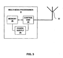
- FIG. 3 is an exemplary block diagram of a programmer 5 that supports a plurality of communication modes for communicating to different medical devices via different telemetry techniques. Programmer 5 is configured to dynamically select different communication modes according to the communication modes presented from medical devices 8. As illustrated, programmer 5 may include an antenna 32, a control unit 34, a memory 36, and a power supply 38.
- Antenna 32 may send and receive different electromagnetic telemetry signals 12, such as radio frequency signals, as directed by control unit 34.
- the invention is not limited for use with electromagnetic telemetry signals, but may also used with other telemetry signals, including sound waves.
- programmer 5 may use the patients flesh as a transmission line for communication of electromagnetic signals between medical devices and programmer 5.
- programmer 5 supports communication according to a plurality of telemetry modes.
- control unit 34 of programmer 5 receives telemetry signals via antenna 32.
- Antenna 32 may be tuned to a large frequency band that covers any possible telemetry signal that may be received from a device supported by programmer 5, or may be periodically tuned by control unit 34 to individual frequencies that correspond to specific telemetry signals that are supported.
- control unit 34 conditions received signals so that signatures associated with the received signals can be identified.
- control unit 34 may perform amplification or attenuation on received signals, and may also implement a phase locked loop to properly synchronize the phase of a received signal with the signatures to which the received signal is being compared.
- the signatures may correspond to templates of expected waveforms that correspond to possible telemetry signals that could be received.
- the signatures may include distinctive waveform characteristics indicative of the respective telemetry signal, such as a particular frequency, amplitude, shape, modulation characteristic, or the like.
- Memory 36 stores the signatures for every telemetry technique that is supported by programmer 5. Accordingly, control unit 34 compares received signals with stored signatures by accessing memory 36. Then, after identifying an acceptable match between a stored signature and a received telemetry signal, e.g., 12A, programmer 5 is able to identify the telemetry technique associated with the medical device that sent signal 12A. In other words, the received signals can be compared to signatures, and the signatures can be mapped to communication modes.
- Memory 36 may also store configuration parameters associated with different communication modes for control unit 34.
- memory 36 may include a lookup table (LUT) that maps signatures to communication modes, i.e., by mapping a number associated with a signature to a number associated with an associated communication mode.
- LUT lookup table
- control unit can access the LUT in memory 36 to select the proper communication mode.
- control unit 34 can be configured according to the selected communication mode to output telemetry signals that the medical device associated with the received telemetry signal 12A can understand.
- control unit 34 can configure itself so that signals sent from the respective device can be properly demodulated and interpreted.
- the different communication modes supported by programmer 5 can be programmed into memory 36, and then applied on a selective basis based on received telemetry signals 12.
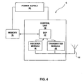
- FIG. 4 is a more detailed exemplary block diagram of programmer 5.
- programmer 5 includes a power supply 38, such as a battery, that powers control unit 34 and memory 36.
- Antenna 32 is coupled to control unit 34 to facilitate the reception and transmission of wireless electromagnetic telemetry signals.
- the invention is not necessarily limited for use with wireless signals or electromagnetic signals.
- Control unit 34 may include a programmable digital signal processor (DSP) 42 coupled to a crystal oscillator (not shown).
- DSP programmable digital signal processor
- DSPs examples include the TI-TMS320C2000 family of DSPs, such as the model number TI-TMS320LC2406 DSP, commercially available from Texas Instruments Incorporated of Dallas Texas, USA.
- the oscillator may comprise a 5 MHz crystal, although other oscillators could be used.
- the TI-TMS320LC2406 DSP is a 16-bit fixed point DSP originally designed for motor control applications.
- the TI-TMS320LC2406 DSP includes internal flash memory and a 10-bit analog to digital converter (ADC). Other DSPs and programmable microprocessors, however, could alternatively be used.
- Memory 36 may comprise a removable memory card that couples to DSP 42 via a memory connector, although non-removable memory could also be used.
- Removable memory cards can provide an added benefit in that the card can be removed from programmer 5 and sent to a physician for analysis. For example, after programmer 5 telemetrically communicates with a given medical device 8, data from that medical device may be stored in memory 36.
- the data stored in memory 36 may be data selected by programmer 5. In some cases, the data stored in memory 36 may be overflow data from an internal memory associated with medical device 8, allowing programmer 5 to provide more continuous and more prolonged patient monitoring capabilities.
- memory 36 comprises a removable card, the card may be removed from programmer 5 and sent to a physician, and a new card may be inserted in its place. In this manner, data from a medical device 8 can be easily provided to a physician, e.g., to facilitate early diagnosis of problems.
- memory cards can avoid the need to send the whole programmer 5 to the physician.
- a more continuous and larger sample of data from the medial device may be captured by sequentially inserting a number of memory cards into programmer 5 over a period of time in which information is being sent from the respective medical device.
- memory 36 may comprise a 64 or 256 Megabyte multimedia memory module commercially available by SanDisk of Sunnyvale, California, USA. Other removable or non-removable memory, however, may also be used.
- Another advances in the art of removable memory cards and a DSP relates to updating the function of the programmer 5.
- a different memory card, storing software to support the new or different telemetry may be provided.
- a DSP configuration with removable memory provides advances in the art in terms of scalability of programmer 5.
- software can be likewise devolved and provided to programmer via a new removable memory card. Accordingly, in that case, the need to develop a different programmer may be avoided.
- new algorithms can be provided to programmer 5 via a new memory card that stores new instructions that can be executed by the DSP.
- Antenna 32 may comprise any of a wide variety of antenna configurations.
- antenna 32 may comprise a substantially flat, co-planer dual opposing coil antenna.
- two opposing coils may be formed on a common substrate to provide two signal inputs to control unit 34.
- the input of two or more signals to control unit 34 may simplify signal processing within control unit 34, such as by simplifying filtering.
- an antenna scheme utilizing multiple concentric and co-planar antenna coils on a substrate may also reduce the form factor of programmer 5, which can facilitate wearable embodiments.
- the use of concentric and co-planar antenna coils may also improve the reception of telemetry signals in a noisy environment.
- Power supply 38 may comprise any of a wide variety of batteries or other power sources.
- power supply 38 may comprise a rechargeable or non-rechargeable battery, such as a polymer or foil battery, a lithium ion batter, a nickel cadmium battery, or the like.
- the battery may have a voltage range of approximately 4.2 to 3.0 volts throughout its useful service life and a capacity of 1.5 Ah, although the invention is not limited in that respect.
- control unit 34 of programmer 5 may include a receiver module 46 and a transmitter module 48.
- Receiver module 46 and transmitter module 48 may be integrated or may comprise separate circuits. The composition of receiver module 46 and transmitter module 48 may depend on the particular DSP 42 used in control unit 34 as well as the particular communication modes supported by programmer 5.
- receiver module 46 conditions a received telemetry signal for analysis by DSP 42.
- Receiver module 46 may include an analog-to-digital converter (ADC), although some DSPs, such as the TI-TMS320LC2406 mentioned above, include an ADC as part of the DSP.
- Receiver module 46 may also include one or more amplifiers, a variable gain amplifier (VGA), one or more filters, automatic gain control (AGC), if needed, and a phase-locked loop for synchronizing a received signal so that an in-phase sample can be identified.
- VGA variable gain amplifier
- AGC automatic gain control
- DSP 42 may configure both itself and receiver module 46 for reception of a given telemetry signal that is expected, such as by selectively switching on a subset of the bandpass filters in DSP 42 and controlling the gain of a received signal in receiver module 46.
- Transmitter module 48 conditions output signals for wireless transmission to a medical device via antenna 38.
- DSP 42 may generate timed output signals based on a selected communication mode in order to communicate with the respective medical device 8 via telemetry.
- Transmitter module 48 can receive signals from DSP 42 and amplify the signals for transmission via antenna 38.
- transmitter module 48 may include transmit circuitry for driving antenna 38, such as a set of field effect transistors (FET) that output relatively large output voltage pulses in response to relatively small input voltages received from DSP 42.
- FET field effect transistors
- Transmitter module 48 may also include various other filters, amplifiers, or the like, that may be selectively activated based on the given communication mode.
- a selected communication mode identified by DSP 42 can cause DSP 42 to send control signals to transmitter module 48 to configure transmitter module 48 for telemetric communication consistent with the selected communication mode.
- transmitter module 48 conditions output signals from DSP 42 for wireless telemetric transmission to a medical device.
- DSP 42 of programmer 5 may include several different bandpass filters and several different demodulators, such as one or more amplitude demodulators, one or more frequency-shift keyed (FSK) demodulators, one or more phase-shift keyed (PSK) demodulators, and the like.
- these different components may be programmed as software or firmware.
- DSP 42 selects the particular bandpass filter(s) and demodulator type to process the digitized signal according to the communication mode that is selected. In other words, DSP compares the raw signal that is received to signatures in order to identify the appropriate communication mode, and then selectively enables the appropriate demodulator so that subsequent signals can be demodulated and interpreted.
- An additional function implemented by DSP 42 may include the control of a variable-gain amplifier (VGA) or other components included in receiver module 46 or transmitter module 48. For example, this may further ensure that the receiver module 46 supplies to the A/D converter of DSP 42 a signal having a desired peak amplitude. Moreover, VGA control in the DSP 42 may provide flexibility in software so that adjustments can be made to properly condition a wide variety of telemetry signals.
- VGA variable-gain amplifier
- receiver module 46 may include a digital-to-analog (D/A) converter to convert a digital control word supplied from DSP 42 to a corresponding analog voltage level for variable-gain amplification.
- D/A digital-to-analog
- programmer 5 may be formed of the exemplary components listed above including the TI-TMS320LC2406 DSP, SanDisk memory module, a dual coil planer antenna, a sufficiently small battery, and individual hardware components to implement the receiver module 46 and transmitter module 48.
- programmer 5 may realize a compact form factor suitable for inconspicuous use by a patient, e.g., to collect information from a medical device and send the memory cards to the physician.
- a minimal amount of communication from programmer 5 to the medical device may prompt the medical device to uplink the requested information.
- such exemplary components may be used to realize a programmer 5 having dimensions less than approximately 60 millimeters by 90 millimeters by 15 millimeters.
- programmer 5 can be made to dimensions corresponding roughly to the size of a thick credit card. Such reduced size can be particularly useful for wearable embodiments of programmer 5.
- programmer 5 may also include an activation switch (not shown), to allow a patient to initiate communication with a medical device. For example, if the patient identifies pain or other problems, it may be desirable to initiate communication, e.g., to cause the medical device to communicate sensed information to programmer 5.
- an activation switch can provide the patient with the ability to ensure that sensed conditions are stored in programmer 5 during periods of time when physical problems may be occurring to the patient.
- programmer 5 may include other user interface features, such as a display screen, a speaker, or a blinking light.
- a display screen e.g., a liquid crystal display
- FIGS. 5 and 6 are diagrams illustrating one embodiment of programmer 5 in the form of an adhesive patch.
- programmer 5 may include an adhesive strip 51 for attaching programmer 5 to a patients skin.
- electrodes 55 may also be used to facilitate the reception of signals though the patients flesh, although the use of electrodes would not be necessary for every embodiment.
- electrodes 55 may provide an alternative to antenna 52 for the transmission and reception of signals. Accordingly, both electrodes 55 and antenna 52 may be electrically coupled to control unit 34.
- Programmer 5 (in this case a patch) is configured to dynamically select different communication modes according to the communication modes presented from medical devices 8.
- programmer 5 may include an antenna 52, a control unit 34, a memory 36, and a power supply 38, an adhesive strip 51, a protective sheath 53 and electrodes 55.
- Antenna 52 may comprise a coplanar dual coil antenna that sends and receives electromagnetic telemetry signals as directed by control unit 34. Alternatively or additionally, electrodes 55 may be used to send and receive the signals.
- the protective sheath 53 may substantially encapsulate one or more of the components of programmer 5.
- programmer 5 (in this case a patch) supports communication according to a plurality of telemetry modes.
- Control unit 34 compares received signals with stored signatures by accessing memory 36. Then, after identifying an acceptable match between a stored signature and a received telemetry signal, programmer 5 is able to identify the telemetry technique associated with the medical device that sent the signal.
- Memory 36 stores the signatures and may also store configuration parameters associated with different communication modes for control unit 34.
- memory 36 may include a lookup table (LUT) that maps signatures to communication modes, i.e., by mapping a number associated with a signature to a number associated with an associated communication mode.
- LUT lookup table
- control unit 34 can access the LUT in memory 36 to select the proper communication mode. Then, control unit 34 can be configured according to the selected communication mode to output telemetry signals that the medical device associated with the received telemetry signal can understand. In addition, control unit 34 can configure itself so that signals sent from the respective device can be properly demodulated and interpreted.
- memory 36 may comprise a removable memory card. Accordingly, memory 36 may be removed from programmer 5, such as via a slot or hole formed in sheath 53. Alternatively, sheath 53 may be pulled back to expose memory 36, allowing memory 36 to be removed or replaced and possibly sent to a physician for analysis.
- programmer 5 may be embodied in a wrist watch, a belt, a necklace, a pendent, a piece of jewelry, an adhesive patch, a pager, a key fob, an identification (ID) card, a laptop computer, a hand-held computer, or other mechanical configurations.
- a programmer 5 having dimensions less than approximately 60 millimeters by 90 millimeters by 15 millimeters can be particularly useful for wearable embodiments.
- a configuration similar that that illustrated in FIGS. 5 and 6 using the exemplary components listed herein may be used to realize a programmer with a small enough form factor to facilitate different wearable embodiments. Additional components may also be added, such as a magnet or electromagnet used to initiate telemetry for some devices.
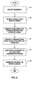
- FIG. 7 is a flow diagram illustrating a technique consistent with the principles of the invention.
- programmer 5 receives a telemetry signal 12 from a medical device 8 (71).
- Control unit 24 of programmer 5 selects a communication mode based on the received signal (72).
- Programmer 5 then communicates with medial device 8 using the selected communication mode (73).
- control unit 24 of programmer 5 may identify a signature associated with the received signal. More specifically, receiver module 46 conditions a received telemetry signal so that it falls within the dynamic range of DSP 42. DSP 42 samples the conditioned signal and compares the digital sample to various signatures stored in memory 36.
- DSP 42 may perform a correlation operation to compare a digital sample of a received signal to various signatures stored in memory 36.
- the correlation operation may compare the frequencies, phase shifts, pulse widths, or any other variable between the digital sample of the received signal to those of the different signatures.
- DSP 42 can configure programmer 5 according to a communication mode associated with the signature. In other words, once the appropriate signature has been identified, DSP 42 can select a communication mode, such as by accessing a LUT in memory 36 that maps signatures to communication modes.
- control unit 34 Upon identifying the necessary communication mode for telemetric communication with a respective medical device 8, control unit 34 configures for such communication. For example, DSP 42 may select an appropriate set of bandpass filters and an appropriate demodulator, each of which may be software implemented as part of DSP 42. In addition, in some cases, DSP 42 may send control signals to receiver module 46 and transmitter module 48 to configure those modules 46, 48 for respective reception and transmission consistent with the selected communication mode. In this manner, programmer 5 can be configured for communication according to a first telemetric mode of communication, and then reconfigured for communication according to a second (different) telemetric mode of communication. In some cases, a large number of different communication modes can be supported by programmer 5.
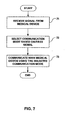
- FIG. 8 is another flow diagram illustrating a technique consistent with the principles of the invention.
- programmer 5 initiates telemetry with a medical device 8 (81).
- the medical device does not send telemetry signals unless it receives a request for such signals.
- programmer 5 can be configured to initiate telemetry with medical devices (81) by sending an appropriate request.
- programmer may perform a plurality of initiation techniques so as to cause any device supported by programmer 5 to send a telemetry signal.
- a magnetic field may be used to initiate telemetry, such as by magnetically activating a switch on the respective device to cause the device to send telemetry signals.
- programmer 5 may include a magnet or an electromagnet that generates the required magnetic field to cause the medical device to send a telemetry signal.
- telemetry from a medical device 8 may begin upon receiving a particular wireless signal that corresponds to a request for telemetry.
- control unit 24 of programmer 5 may be configured to send one or more different request signals to provoke a response from the medical device.
- control unit 24 may send different request signals over time to provoke responses from different medical devices for which programmer 5 supports telemetry. Thus, if a particular device is in proximity to programmer 5, eventually the appropriate request signal will be sent from programmer 5 to that device.
- programmer 5 receives the signal from the medical device (81) causing the medical device to send a telemetry signal
- programmer 5 receives the signal from the medical device (82).
- Control unit 24 of programmer 5 identifies a signature stored in memory 26 that correlates with the received signal (83). More specifically, DSP 42 generates a digital sample based on a signal conditioned by receiver module 46, and compares the digital sample to the signatures stored in memory by invoking a correlation operation.
- control unit 24 Upon identifying a signature stored in memory 26 that correlates with the received signal (83), control unit 24 identifies a medical device associated with the signature (84). More specifically, DSP 42 accesses a LUT in memory 26 which maps signatures to communication modes, and selects from the LUT, the communication mode associated with the identified signature.
- Control unit 24 then configures programmer 5 for communication with the medical device 5 according to the selected communication mode (85). More specifically, DSP 42 selects particular bandpass filter(s) and a demodulator to process received telemetry signals in accordance with the communication mode that is selected. In addition, DSP 42 may send control signals to one or more components included in receiver module 46 or transmitter module 48 to configure the modules to condition received signals and to condition output signals according to the communication mode that is selected. Programmer 5 can then telemetrically communicate with the medical device (86). This telemetric communication may be used for any of a wide variety of desirable communication that can occur between a programmer and a medical device. For example, programmer 5 may telemetrically communicate with the medical device to program a new therapy technique into the medical device.
- device 5 may be configured to receive input from a physician or medical personnel specifying a therapy to be performed, and may send a signal to the medical device according to the selected communication mode to direct the medical device to perform the therapy.
- programmer 5 may telemetrically communicate with the medical device 8 to request stored information corresponding, for example, to diagnostic information, sensed conditions associated with the patient, information relating to therapy delivered to the patient, or any other information collected or identified by the medical device.
- programmer 5 may receive the requested information from the medical device in response to the request for stored information sent according to the appropriately selected communication mode.
- These or other communications may occur between a medical device and programmer 8 once programmer has identified the appropriate communication mode, and configured according to that communication mode consistent with the principles of the invention.
- the programmer may take a variety of forms and mechanical configurations in addition to those described herein.
- the techniques described herein may be implemented in a programmer in hardware, software, firmware, or any combination thereof.
- invention may be directed to a computer readable medium comprising program code, that when executed, performs one or more of the techniques described herein.
- the computer readable medium may comprise a random access memory (RAM), SDRAM, FLASH, or possibly a removable memory card as outlined herein.
- the memory stores the computer readable instructions that, when executed cause programmer 5 to carry out the techniques described herein.
Landscapes
- Health & Medical Sciences (AREA)
- Life Sciences & Earth Sciences (AREA)
- Biophysics (AREA)
- Heart & Thoracic Surgery (AREA)
- Engineering & Computer Science (AREA)
- Biomedical Technology (AREA)
- Nuclear Medicine, Radiotherapy & Molecular Imaging (AREA)
- Radiology & Medical Imaging (AREA)
- Animal Behavior & Ethology (AREA)
- General Health & Medical Sciences (AREA)
- Public Health (AREA)
- Veterinary Medicine (AREA)
- Electrotherapy Devices (AREA)
- Measuring And Recording Apparatus For Diagnosis (AREA)
Abstract
Claims (22)
- Procédé pour réaliser une communication entre un programmateur (5) et une pluralité de différents dispositifs médicaux (8) qui communiquent avec ledit programmateur en utilisant différents types de techniques de télémétrie respectives, ledit procédé comportant les étapes consistant à :fournir un programmateur ayant une pluralité de types possibles de techniques de communication de télémétrie mémorisées dans une mémoire (36) de celui-ci ;recevoir dans une unité de commande dudit programmateur un premier signal provenant d'un dispositif médical ; etsélectionner par l'intermédiaire de ladite unité de commande un type de technique de communication parmi ladite pluralité de possibles techniques de communication d'après le premier signal, pour communiquer avec ledit dispositif médical.
- Procédé selon la revendication 1, dans lequel la sélection de la technique de communication sur la base du premier signal inclut de plus :l'identification d'une signature qui est sensiblement corrélée au premier signal ; etla sélection d'un type de technique de communication d'après la signature.
- Procédé selon la revendication 1, comportant de plus :la génération d'un second signal qui s'accorde avec le type sélectionné de technique de communication ; etl'envoi du second signal au dispositif médical.
- Procédé selon la revendication 3, dans lequel le second signal demande des informations dans le dispositif médical, le procédé comportant de plus la réception d'informations demandées depuis le dispositif médical en réponse au second signal.
- Procédé selon l'une quelconque des revendications précédentes, dans lequel la sélection du type de technique de communication parmi une pluralité de possibles types de techniques de communication sur la base du premier signal inclut :l'accès à une table de consultation qui mappe des numéros associés à des signatures en des numéros associés à de possibles types de techniques de communication ;l'identification d'une signature qui est sensiblement corrélée au premier signal ; etla sélection du type de technique de communication d'après la signature identifiée en utilisant la table de consultation.
- Procédé selon la revendication 5, comportant de plus la configuration d'un circuit de transmission (46, 48, 32) pour communiquer avec le dispositif médical conformément au type de technique de communication sélectionné.
- Procédé selon l'une quelconque des revendications précédentes, comportant de plus le lancement d'une télémétrie pour amener le dispositif médical à envoyer le premier signal.
- Procédé selon la revendication 7, dans lequel le lancement de télémétrie inclut l'exécution d'une pluralité de types possibles de techniques de lancement de télémétrie.
- Programmateur pour une pluralité de différents dispositifs médicaux qui communiquent avec le programmateur en utilisant différents types de techniques de télémétrie, ledit programmateur comportant:une mémoire (36) mémorisant une pluralité de types possibles de techniques de communication de télémétrie pour le programmateur ; etune unité de commande (34) pour recevoir un premier signal depuis un dispositif médical (8) et sélectionner l'un des types de techniques de communication d'après le premier signal pour communiquer avec ledit dispositif médical.
- Programmateur selon la revendication 9, dans lequel l'unité de commande sélectionne le type de technique de communication d'après le premier signal en :identifiant une signature qui est sensiblement corrélée au premier signal ; etsélectionnant un type de technique de communication associé à la signature.
- Programmateur selon la revendication 9, l'unité de commande étant configurée pour :générer un second signal qui s'accorde avec le type de technique de communication sélectionné ; etenvoyer le second signal au dispositif médical.
- Programmateur selon la revendication 11, dans lequel le second signal demande des informations dans le dispositif médical, dans lequel l'unité de commande reçoit des informations demandées à partir du dispositif médical en réponse au second signal.
- Programmateur selon l'une quelconque des revendications 9 à 12, l'unité de commande étant configurée pour :recevoir une entrée spécifiant une thérapie;générer un second signal qui s'accorde avec le type de technique de communication sélectionné pour programmer le dispositif médical de manière à mettre en oeuvre la thérapie ; etenvoyer le second signal au dispositif médical.
- Programmateur selon l'une quelconque des revendications 9 à 13, dans lequel la mémoire mémorise une table de consultation qui mappe des numéros associés à la pluralité de types possibles de techniques de communication en des numéros associés à un ensemble de signatures, et dans lequel l'unité de commande sélectionne la technique de communication parmi une pluralité de types possibles de techniques de communication sur la base du premier signal en :accédant à la table de consultation ;identifiant une signature qui est sensiblement corrélée au premier signal ; etsélectionnant le type de technique de communication d'après la signature identifiée en utilisant la table de consultation.
- Programmateur selon la revendication 14, dans lequel l'unité de commande est configurée pour communiquer avec le dispositif médical en conformité avec le type de technique de communication sélectionné.
- Programmateur selon l'une quelconque des revendications 9 à 15, l'unité de commande étant configurée pour lancer une télémétrie pour amener le dispositif médical à envoyer le premier signal.
- Programmateur selon la revendication 16, dans lequel l'unité de commande lance une télémétrie en effectuant une pluralité de techniques de lancement de télémétrie possibles.
- Programmateur selon l'une quelconque des revendications 9 à 17, dans lequel le programmateur forme au moins une partie d'un dispositif sélectionné parmi le groupe suivant : une montre-bracelet, une ceinture, un collier, une partie de bijou, un timbre adhésif, un téléavertisseur, un porte-clé, une carte d'identification, un ordinateur portable, un interrogateur, et un ordinateur portatif.
- Programmateur selon l'une quelconque des revendications 9 à 18, dans lequel la mémoire comporte une carte mémoire amovible.
- Programmateur selon l'une quelconque des revendications 9 à 19, comportant de plus un activateur de patient pour permettre au patient d'activer le programmateur.
- Programmateur selon l'une quelconque des revendications 9 à 20, comportant de plus un dispositif de rétroaction pour indiquer à un patient qu'une communication télémétrique a été lancée.
- Code de programme destiné à être exécuté par un processeur dans un programmateur selon l'une quelconque des revendications 9 à 21, de sorte que le programme code le procédé selon l'une quelconque des revendications 1 à 8.
Applications Claiming Priority (3)
| Application Number | Priority Date | Filing Date | Title |
|---|---|---|---|
| US10/261,317 US20040064166A1 (en) | 2002-09-30 | 2002-09-30 | Multi-mode programmer for medical device communication |
| US261317 | 2002-09-30 | ||
| PCT/US2003/030109 WO2004030757A1 (fr) | 2002-09-30 | 2003-09-25 | Programmateur multimode destine a une communication avec un dispositif medical |
Publications (2)
| Publication Number | Publication Date |
|---|---|
| EP1554012A1 EP1554012A1 (fr) | 2005-07-20 |
| EP1554012B1 true EP1554012B1 (fr) | 2007-08-01 |
Family
ID=32029954
Family Applications (1)
| Application Number | Title | Priority Date | Filing Date |
|---|---|---|---|
| EP03770411A Expired - Lifetime EP1554012B1 (fr) | 2002-09-30 | 2003-09-25 | Programmateur multimode destine a une communication avec un dispositif medical |
Country Status (4)
| Country | Link |
|---|---|
| US (1) | US20040064166A1 (fr) |
| EP (1) | EP1554012B1 (fr) |
| DE (1) | DE60315327T2 (fr) |
| WO (1) | WO2004030757A1 (fr) |
Cited By (8)
| Publication number | Priority date | Publication date | Assignee | Title |
|---|---|---|---|---|
| US9643022B2 (en) | 2013-06-17 | 2017-05-09 | Nyxoah SA | Flexible control housing for disposable patch |
| US9849289B2 (en) | 2009-10-20 | 2017-12-26 | Nyxoah SA | Device and method for snoring detection and control |
| US9855032B2 (en) | 2012-07-26 | 2018-01-02 | Nyxoah SA | Transcutaneous power conveyance device |
| US9943686B2 (en) | 2009-10-20 | 2018-04-17 | Nyxoah SA | Method and device for treating sleep apnea based on tongue movement |
| US10052097B2 (en) | 2012-07-26 | 2018-08-21 | Nyxoah SA | Implant unit delivery tool |
| US10751537B2 (en) | 2009-10-20 | 2020-08-25 | Nyxoah SA | Arced implant unit for modulation of nerves |
| US10814137B2 (en) | 2012-07-26 | 2020-10-27 | Nyxoah SA | Transcutaneous power conveyance device |
| US11253712B2 (en) | 2012-07-26 | 2022-02-22 | Nyxoah SA | Sleep disordered breathing treatment apparatus |
Families Citing this family (33)
| Publication number | Priority date | Publication date | Assignee | Title |
|---|---|---|---|---|
| US6974437B2 (en) * | 2000-01-21 | 2005-12-13 | Medtronic Minimed, Inc. | Microprocessor controlled ambulatory medical apparatus with hand held communication device |
| US10322284B2 (en) * | 2003-07-18 | 2019-06-18 | The John Hopkins University | Method for treating nausea and vomiting by vagus nerve stimulation with selectable stimulation modes |
| US7561921B2 (en) | 2003-10-02 | 2009-07-14 | Medtronic, Inc. | Neurostimulator programmer with internal antenna |
| US7263406B2 (en) * | 2003-10-02 | 2007-08-28 | Medtronic, Inc. | Medical device programmer with selective disablement of display during telemetry |
| US7729766B2 (en) | 2003-10-02 | 2010-06-01 | Medtronic, Inc. | Circuit board construction for handheld programmer |
| US20050075685A1 (en) * | 2003-10-02 | 2005-04-07 | Forsberg John W. | Medical device programmer with infrared communication |
| US7203549B2 (en) * | 2003-10-02 | 2007-04-10 | Medtronic, Inc. | Medical device programmer with internal antenna and display |
| US7272445B2 (en) * | 2003-10-02 | 2007-09-18 | Medtronic, Inc. | Medical device programmer with faceplate |
| US7356369B2 (en) | 2003-10-02 | 2008-04-08 | Medtronic, Inc. | Z-axis assembly of medical device programmer |
| US7991479B2 (en) | 2003-10-02 | 2011-08-02 | Medtronic, Inc. | Neurostimulator programmer with clothing attachable antenna |
| US8442643B2 (en) * | 2003-10-02 | 2013-05-14 | Medtronic, Inc. | Medical device programmer with reduced-noise power supply |
| US8176922B2 (en) | 2004-06-29 | 2012-05-15 | Depuy Products, Inc. | System and method for bidirectional communication with an implantable medical device using an implant component as an antenna |
| US7384403B2 (en) | 2004-12-17 | 2008-06-10 | Depuy Products, Inc. | Wireless communication system for transmitting information from a medical device |
| US7896869B2 (en) | 2004-12-29 | 2011-03-01 | Depuy Products, Inc. | System and method for ensuring proper medical instrument use in an operating room |
| US8001975B2 (en) | 2004-12-29 | 2011-08-23 | Depuy Products, Inc. | Medical device communications network |
| US8160704B2 (en) * | 2005-11-02 | 2012-04-17 | Cardiac Pacemakers, Inc. | System and method for enabling relayed communications by implantable medical devices |
| US20070163588A1 (en) * | 2005-11-08 | 2007-07-19 | Jack Hebrank | Respirators for Delivering Clean Air to an Individual User |
| US7843328B2 (en) | 2005-11-22 | 2010-11-30 | Covidien Ag | Medical device with selectable status monitoring modes |
| US20070135855A1 (en) * | 2005-12-13 | 2007-06-14 | Foshee Phillip D | Patient management device for portably interfacing with a plurality of implantable medical devices and method thereof |
| US8718773B2 (en) | 2007-05-23 | 2014-05-06 | Ebr Systems, Inc. | Optimizing energy transmission in a leadless tissue stimulation system |
| US8080064B2 (en) | 2007-06-29 | 2011-12-20 | Depuy Products, Inc. | Tibial tray assembly having a wireless communication device |
| WO2009036260A1 (fr) * | 2007-09-14 | 2009-03-19 | Corventis, Inc. | Collecte de données dans un moniteur patient à plusieurs capteurs |
| WO2009051536A1 (fr) * | 2007-10-16 | 2009-04-23 | Milux Holding Sa | Procédé et appareil pour fournir de l'énergie à un dispositif médical |
| US20090210798A1 (en) * | 2008-02-19 | 2009-08-20 | Cardiac Pacemakers, Inc. | Media presentation for use with implantable device |
| WO2009120636A1 (fr) * | 2008-03-25 | 2009-10-01 | Ebr Systems, Inc. | Connexion d’électrode temporaire pour des systèmes de stimulation sans fil |
| US9821166B2 (en) * | 2008-05-27 | 2017-11-21 | Medtronic, Inc. | Indication of coupling between medical devices |
| EP2233067A1 (fr) * | 2009-03-23 | 2010-09-29 | Roche Diagnostics GmbH | Système médical doté d'une fonction plug-and-play |
| DE202010010220U1 (de) * | 2010-07-13 | 2010-10-14 | Osypka, Peter, Dr.-Ing. | Zentrale Steuereinheit von Implantaten |
| US9713721B2 (en) * | 2010-11-10 | 2017-07-25 | Boston Scientific Neuromodulation Corporation | System and method for storing application specific and lead configuration information in neurostimulation device |
| US20130197607A1 (en) | 2011-06-28 | 2013-08-01 | Greatbatch Ltd. | Dual patient controllers |
| US20130006330A1 (en) * | 2011-06-28 | 2013-01-03 | Greatbatch, Ltd. | Dual patient controllers |
| US9649165B2 (en) * | 2012-07-16 | 2017-05-16 | Cardiac Innovation, Llc | Medical device identifier |
| US12350497B2 (en) | 2022-02-10 | 2025-07-08 | Ebr Systems, Inc. | Tissue stimulation systems and methods, such as for pacing cardiac tissue |
Family Cites Families (24)
| Publication number | Priority date | Publication date | Assignee | Title |
|---|---|---|---|---|
| US4556063A (en) * | 1980-10-07 | 1985-12-03 | Medtronic, Inc. | Telemetry system for a medical device |
| US5354319A (en) * | 1990-01-22 | 1994-10-11 | Medtronic, Inc. | Telemetry system for an implantable medical device |
| US5127404A (en) * | 1990-01-22 | 1992-07-07 | Medtronic, Inc. | Telemetry format for implanted medical device |
| US5113869A (en) * | 1990-08-21 | 1992-05-19 | Telectronics Pacing Systems, Inc. | Implantable ambulatory electrocardiogram monitor |
| US5345362A (en) * | 1993-04-29 | 1994-09-06 | Medtronic, Inc. | Portable computer apparatus with articulating display panel |
| US5350411A (en) * | 1993-06-28 | 1994-09-27 | Medtronic, Inc. | Pacemaker telemetry system |
| US5466246A (en) * | 1994-07-29 | 1995-11-14 | Pacesetter, Inc. | Telemetry receiver for implantable device, incorporating digital signal processing |
| US5626630A (en) * | 1994-10-13 | 1997-05-06 | Ael Industries, Inc. | Medical telemetry system using an implanted passive transponder |
| US5752976A (en) * | 1995-06-23 | 1998-05-19 | Medtronic, Inc. | World wide patient location and data telemetry system for implantable medical devices |
| US6083248A (en) * | 1995-06-23 | 2000-07-04 | Medtronic, Inc. | World wide patient location and data telemetry system for implantable medical devices |
| US5683432A (en) * | 1996-01-11 | 1997-11-04 | Medtronic, Inc. | Adaptive, performance-optimizing communication system for communicating with an implanted medical device |
| FI960636L (fi) * | 1996-02-12 | 1997-08-13 | Nokia Mobile Phones Ltd | Menetelmä potilaan terveydentilan valvomiseksi |
| US5999857A (en) * | 1996-12-18 | 1999-12-07 | Medtronic, Inc. | Implantable device telemetry system and method |
| US5836975A (en) * | 1996-12-19 | 1998-11-17 | Medtronic, Inc. | Method and apparatus for diagnosis and treatment of arrhythmias |
| US5752977A (en) * | 1997-04-15 | 1998-05-19 | Medtronic, Inc. | Efficient high data rate telemetry format for implanted medical device |
| US5987356A (en) * | 1997-06-05 | 1999-11-16 | Medtronic, Inc. | Method and apparatus for diagnosis and treatment of arrhythmias |
| US6200265B1 (en) * | 1999-04-16 | 2001-03-13 | Medtronic, Inc. | Peripheral memory patch and access method for use with an implantable medical device |
| US6167312A (en) * | 1999-04-30 | 2000-12-26 | Medtronic, Inc. | Telemetry system for implantable medical devices |
| US6169925B1 (en) * | 1999-04-30 | 2001-01-02 | Medtronic, Inc. | Telemetry system for implantable medical devices |
| US6804558B2 (en) * | 1999-07-07 | 2004-10-12 | Medtronic, Inc. | System and method of communicating between an implantable medical device and a remote computer system or health care provider |
| US6298271B1 (en) * | 1999-07-19 | 2001-10-02 | Medtronic, Inc. | Medical system having improved telemetry |
| US6263245B1 (en) * | 1999-08-12 | 2001-07-17 | Pacesetter, Inc. | System and method for portable implantable device interogation |
| USD438204S1 (en) * | 2000-02-14 | 2001-02-27 | Medtronic, Inc. | Programmer for use with implantable medical device |
| US6443891B1 (en) * | 2000-09-20 | 2002-09-03 | Medtronic, Inc. | Telemetry modulation protocol system for medical devices |
-
2002
- 2002-09-30 US US10/261,317 patent/US20040064166A1/en not_active Abandoned
-
2003
- 2003-09-25 WO PCT/US2003/030109 patent/WO2004030757A1/fr not_active Ceased
- 2003-09-25 EP EP03770411A patent/EP1554012B1/fr not_active Expired - Lifetime
- 2003-09-25 DE DE60315327T patent/DE60315327T2/de not_active Expired - Lifetime
Cited By (19)
| Publication number | Priority date | Publication date | Assignee | Title |
|---|---|---|---|---|
| US10751537B2 (en) | 2009-10-20 | 2020-08-25 | Nyxoah SA | Arced implant unit for modulation of nerves |
| US9849289B2 (en) | 2009-10-20 | 2017-12-26 | Nyxoah SA | Device and method for snoring detection and control |
| US11857791B2 (en) | 2009-10-20 | 2024-01-02 | Nyxoah SA | Arced implant unit for modulation of nerves |
| US9943686B2 (en) | 2009-10-20 | 2018-04-17 | Nyxoah SA | Method and device for treating sleep apnea based on tongue movement |
| US9950166B2 (en) | 2009-10-20 | 2018-04-24 | Nyxoah SA | Acred implant unit for modulation of nerves |
| US11273307B2 (en) | 2009-10-20 | 2022-03-15 | Nyxoah SA | Method and device for treating sleep apnea |
| US10898717B2 (en) | 2009-10-20 | 2021-01-26 | Nyxoah SA | Device and method for snoring detection and control |
| US10716940B2 (en) | 2009-10-20 | 2020-07-21 | Nyxoah SA | Implant unit for modulation of small diameter nerves |
| US10716560B2 (en) | 2012-07-26 | 2020-07-21 | Nyxoah SA | Implant unit delivery tool |
| US10814137B2 (en) | 2012-07-26 | 2020-10-27 | Nyxoah SA | Transcutaneous power conveyance device |
| US10918376B2 (en) | 2012-07-26 | 2021-02-16 | Nyxoah SA | Therapy protocol activation triggered based on initial coupling |
| US11253712B2 (en) | 2012-07-26 | 2022-02-22 | Nyxoah SA | Sleep disordered breathing treatment apparatus |
| US10052097B2 (en) | 2012-07-26 | 2018-08-21 | Nyxoah SA | Implant unit delivery tool |
| US11730469B2 (en) | 2012-07-26 | 2023-08-22 | Nyxoah SA | Implant unit delivery tool |
| US9855032B2 (en) | 2012-07-26 | 2018-01-02 | Nyxoah SA | Transcutaneous power conveyance device |
| US9643022B2 (en) | 2013-06-17 | 2017-05-09 | Nyxoah SA | Flexible control housing for disposable patch |
| US10512782B2 (en) | 2013-06-17 | 2019-12-24 | Nyxoah SA | Remote monitoring and updating of a medical device control unit |
| US11298549B2 (en) | 2013-06-17 | 2022-04-12 | Nyxoah SA | Control housing for disposable patch |
| US11642534B2 (en) | 2013-06-17 | 2023-05-09 | Nyxoah SA | Programmable external control unit |
Also Published As
| Publication number | Publication date |
|---|---|
| US20040064166A1 (en) | 2004-04-01 |
| EP1554012A1 (fr) | 2005-07-20 |
| DE60315327T2 (de) | 2008-01-03 |
| WO2004030757A1 (fr) | 2004-04-15 |
| DE60315327D1 (de) | 2007-09-13 |
Similar Documents
| Publication | Publication Date | Title |
|---|---|---|
| EP1554012B1 (fr) | Programmateur multimode destine a une communication avec un dispositif medical | |
| WO2005053786A2 (fr) | Programmateur multimode pour une communication avec des dispositifs medicaux | |
| US4543955A (en) | System for controlling body implantable action device | |
| US7792588B2 (en) | Radio frequency transponder based implantable medical system | |
| EP1458444B1 (fr) | Dispositif medical implantable comportant deux ou davantage de systemes de telemetrie | |
| US20240198114A1 (en) | Facilitating acceleration of advertising rates for medical devices | |
| US7742816B2 (en) | Multichannel communication for implantable medical device applications | |
| US6115636A (en) | Telemetry for implantable devices using the body as an antenna | |
| EP2131923B1 (fr) | Procédé et système d'initialisation d'une communication entre un dispositif de surveillance domestique et un dispositif médical implantable | |
| US10736509B2 (en) | Dual frequency control for a physiologic monitor | |
| US20100249882A1 (en) | Acoustic Telemetry System for Communication with an Implantable Medical Device | |
| US12144580B2 (en) | System and method for managing Bluetooth Low Energy advertising | |
| WO2011072183A2 (fr) | Système de neurostimulation implantable | |
| CN105828756B (zh) | 用于听力植入物的有源遥测响应 | |
| US12434064B2 (en) | Inductive charging coil configuration for an implantable medical device | |
| EP4070853B1 (fr) | Systèmes et procédés de programmation à distance de, et autres capacités de suivi avec, des stimulateurs cardiaques sans fil | |
| EP4480533A2 (fr) | Systèmes et procédés de programmation à distance de, et d'autres capacités de suivi avec, des stimulateurs cardiaques sans fil | |
| WO2023156212A1 (fr) | Ensemble collecteur | |
| US20250242163A1 (en) | Devices, systems and methods for improving conductive communication between external devices and implantable medical devices | |
| US20240390691A1 (en) | Wearable assemblies for tissue stimulation |
Legal Events
| Date | Code | Title | Description |
|---|---|---|---|
| PUAI | Public reference made under article 153(3) epc to a published international application that has entered the european phase |
Free format text: ORIGINAL CODE: 0009012 |
|
| 17P | Request for examination filed |
Effective date: 20050422 |
|
| AK | Designated contracting states |
Kind code of ref document: A1 Designated state(s): AT BE BG CH CY CZ DE DK EE ES FI FR GB GR HU IE IT LI LU MC NL PT RO SE SI SK TR |
|
| RBV | Designated contracting states (corrected) |
Designated state(s): CH DE FR LI NL SE |
|
| 17Q | First examination report despatched |
Effective date: 20060112 |
|
| 17Q | First examination report despatched |
Effective date: 20060112 |
|
| GRAP | Despatch of communication of intention to grant a patent |
Free format text: ORIGINAL CODE: EPIDOSNIGR1 |
|
| GRAS | Grant fee paid |
Free format text: ORIGINAL CODE: EPIDOSNIGR3 |
|
| GRAA | (expected) grant |
Free format text: ORIGINAL CODE: 0009210 |
|
| AK | Designated contracting states |
Kind code of ref document: B1 Designated state(s): CH DE FR LI NL SE |
|
| REG | Reference to a national code |
Ref country code: CH Ref legal event code: EP |
|
| REF | Corresponds to: |
Ref document number: 60315327 Country of ref document: DE Date of ref document: 20070913 Kind code of ref document: P |
|
| REG | Reference to a national code |
Ref country code: CH Ref legal event code: NV Representative=s name: A. BRAUN, BRAUN, HERITIER, ESCHMANN AG PATENTANWAE |
|
| REG | Reference to a national code |
Ref country code: SE Ref legal event code: TRGR |
|
| PGFP | Annual fee paid to national office [announced via postgrant information from national office to epo] |
Ref country code: CH Payment date: 20070828 Year of fee payment: 5 |
|
| ET | Fr: translation filed | ||
| PGFP | Annual fee paid to national office [announced via postgrant information from national office to epo] |
Ref country code: NL Payment date: 20070806 Year of fee payment: 5 |
|
| PLBE | No opposition filed within time limit |
Free format text: ORIGINAL CODE: 0009261 |
|
| STAA | Information on the status of an ep patent application or granted ep patent |
Free format text: STATUS: NO OPPOSITION FILED WITHIN TIME LIMIT |
|
| REG | Reference to a national code |
Ref country code: CH Ref legal event code: PFA Owner name: MEDTRONIC, INC. Free format text: MEDTRONIC, INC.#710 MEDTRONIC PARKWAY LC340#MINNEAPOLIS, MN 55432 (US) -TRANSFER TO- MEDTRONIC, INC.#710 MEDTRONIC PARKWAY LC340#MINNEAPOLIS, MN 55432 (US) |
|
| 26N | No opposition filed |
Effective date: 20080506 |
|
| REG | Reference to a national code |
Ref country code: CH Ref legal event code: PL |
|
| PG25 | Lapsed in a contracting state [announced via postgrant information from national office to epo] |
Ref country code: NL Free format text: LAPSE BECAUSE OF NON-PAYMENT OF DUE FEES Effective date: 20090401 |
|
| NLV4 | Nl: lapsed or anulled due to non-payment of the annual fee |
Effective date: 20090401 |
|
| PGFP | Annual fee paid to national office [announced via postgrant information from national office to epo] |
Ref country code: SE Payment date: 20070802 Year of fee payment: 5 |
|
| PG25 | Lapsed in a contracting state [announced via postgrant information from national office to epo] |
Ref country code: LI Free format text: LAPSE BECAUSE OF NON-PAYMENT OF DUE FEES Effective date: 20080930 Ref country code: CH Free format text: LAPSE BECAUSE OF NON-PAYMENT OF DUE FEES Effective date: 20080930 |
|
| PG25 | Lapsed in a contracting state [announced via postgrant information from national office to epo] |
Ref country code: SE Free format text: LAPSE BECAUSE OF NON-PAYMENT OF DUE FEES Effective date: 20080926 |
|
| REG | Reference to a national code |
Ref country code: FR Ref legal event code: PLFP Year of fee payment: 14 |
|
| PGFP | Annual fee paid to national office [announced via postgrant information from national office to epo] |
Ref country code: FR Payment date: 20160926 Year of fee payment: 14 |
|
| PGFP | Annual fee paid to national office [announced via postgrant information from national office to epo] |
Ref country code: DE Payment date: 20160928 Year of fee payment: 14 |
|
| REG | Reference to a national code |
Ref country code: DE Ref legal event code: R119 Ref document number: 60315327 Country of ref document: DE |
|
| REG | Reference to a national code |
Ref country code: FR Ref legal event code: ST Effective date: 20180531 |
|
| PG25 | Lapsed in a contracting state [announced via postgrant information from national office to epo] |
Ref country code: DE Free format text: LAPSE BECAUSE OF NON-PAYMENT OF DUE FEES Effective date: 20180404 |
|
| PG25 | Lapsed in a contracting state [announced via postgrant information from national office to epo] |
Ref country code: FR Free format text: LAPSE BECAUSE OF NON-PAYMENT OF DUE FEES Effective date: 20171002 |