EP1553821B1 - Tagging animals - Google Patents
Tagging animals Download PDFInfo
- Publication number
- EP1553821B1 EP1553821B1 EP03809213A EP03809213A EP1553821B1 EP 1553821 B1 EP1553821 B1 EP 1553821B1 EP 03809213 A EP03809213 A EP 03809213A EP 03809213 A EP03809213 A EP 03809213A EP 1553821 B1 EP1553821 B1 EP 1553821B1
- Authority
- EP
- European Patent Office
- Prior art keywords
- ear
- penetrating
- animal
- component
- transponder
- Prior art date
- Legal status (The legal status is an assumption and is not a legal conclusion. Google has not performed a legal analysis and makes no representation as to the accuracy of the status listed.)
- Expired - Lifetime
Links
- 241001465754 Metazoa Species 0.000 title claims abstract description 80
- 230000000149 penetrating effect Effects 0.000 claims abstract description 75
- 239000000463 material Substances 0.000 claims abstract description 21
- 230000000295 complement effect Effects 0.000 claims abstract description 17
- 238000005304 joining Methods 0.000 claims description 42
- 239000004033 plastic Substances 0.000 claims description 7
- 229920003023 plastic Polymers 0.000 claims description 7
- 239000002991 molded plastic Substances 0.000 claims description 3
- 238000000926 separation method Methods 0.000 claims 1
- 230000011664 signaling Effects 0.000 claims 1
- 239000000126 substance Substances 0.000 claims 1
- 210000003128 head Anatomy 0.000 description 24
- 241001494479 Pecora Species 0.000 description 14
- 239000003550 marker Substances 0.000 description 14
- 241000283690 Bos taurus Species 0.000 description 13
- 239000007943 implant Substances 0.000 description 10
- 235000013290 Sagittaria latifolia Nutrition 0.000 description 9
- 235000015246 common arrowhead Nutrition 0.000 description 9
- 230000002792 vascular Effects 0.000 description 9
- 210000003462 vein Anatomy 0.000 description 7
- 208000015181 infectious disease Diseases 0.000 description 5
- 125000006850 spacer group Chemical group 0.000 description 4
- 238000003466 welding Methods 0.000 description 4
- 206010052428 Wound Diseases 0.000 description 3
- 208000027418 Wounds and injury Diseases 0.000 description 3
- 238000000034 method Methods 0.000 description 3
- 230000000717 retained effect Effects 0.000 description 3
- 239000004433 Thermoplastic polyurethane Substances 0.000 description 2
- 238000004026 adhesive bonding Methods 0.000 description 2
- 244000309466 calf Species 0.000 description 2
- 238000010276 construction Methods 0.000 description 2
- 229920001971 elastomer Polymers 0.000 description 2
- 230000035876 healing Effects 0.000 description 2
- 239000005060 rubber Substances 0.000 description 2
- 229920002803 thermoplastic polyurethane Polymers 0.000 description 2
- 101100328086 Caenorhabditis elegans cla-1 gene Proteins 0.000 description 1
- 241000283073 Equus caballus Species 0.000 description 1
- 206010061218 Inflammation Diseases 0.000 description 1
- 229910000831 Steel Inorganic materials 0.000 description 1
- 238000007792 addition Methods 0.000 description 1
- 230000004075 alteration Effects 0.000 description 1
- 210000003484 anatomy Anatomy 0.000 description 1
- 230000005540 biological transmission Effects 0.000 description 1
- 239000002775 capsule Substances 0.000 description 1
- 230000008859 change Effects 0.000 description 1
- 238000005520 cutting process Methods 0.000 description 1
- 210000000624 ear auricle Anatomy 0.000 description 1
- 210000005069 ears Anatomy 0.000 description 1
- 230000004054 inflammatory process Effects 0.000 description 1
- 238000002347 injection Methods 0.000 description 1
- 239000007924 injection Substances 0.000 description 1
- 230000007794 irritation Effects 0.000 description 1
- 239000002184 metal Substances 0.000 description 1
- 238000012986 modification Methods 0.000 description 1
- 230000004048 modification Effects 0.000 description 1
- 238000012544 monitoring process Methods 0.000 description 1
- 230000035515 penetration Effects 0.000 description 1
- 229920002635 polyurethane Polymers 0.000 description 1
- 239000004814 polyurethane Substances 0.000 description 1
- 230000008569 process Effects 0.000 description 1
- 239000010959 steel Substances 0.000 description 1
Images




Classifications
-
- A—HUMAN NECESSITIES
- A01—AGRICULTURE; FORESTRY; ANIMAL HUSBANDRY; HUNTING; TRAPPING; FISHING
- A01K—ANIMAL HUSBANDRY; AVICULTURE; APICULTURE; PISCICULTURE; FISHING; REARING OR BREEDING ANIMALS, NOT OTHERWISE PROVIDED FOR; NEW BREEDS OF ANIMALS
- A01K11/00—Marking of animals
- A01K11/001—Ear-tags
- A01K11/004—Ear-tags with electronic identification means, e.g. transponders
Definitions
- the present invention relates in general terms to improvements in or relating to animal tagging and to methods for tagging animals. More particularly, but not exclusively, the invention relates to an improved tag label or like means (hereinafter referred to as "a tag") for use with animals for a range of purposes which may include allowing for ready identification and/or tracking thereof (for whatever reason).
- a tag is disclosed in document FR-A-2 141 806 .
- the tagging of animals for purposes of ready identification, tracking or monitoring of movements, etc has involved the use of a tag or the like means of a unitary kind having first and second portions held together, at or adjacent an extremity of each portion, by an intermediate region.
- the arrangement is such that a distal extremity of a first portion can be passed through an aperture made in the ear of the animal, for example, with the overall tag then being arranged such that the intermediate portion rests positioned through the ear and the respective first and second portions extend, at least to some extent, over the ear of the animal.
- Such a form of tag has enjoyed wide acceptance and is applied by taking an appropriate applicator or tool to make a hole in the ear of the animal (be it a sheep, cow, horse or in fact any type of animal, domestic or otherwise) just in from an edge thereof, then prising the respective first and second portions of the aforementioned tag apart so as to enable one of those portions to be inserted through the hole thus created, the two portions then being manipulated into such a condition that the intermediate portion rests through the hole formed in the ear of the animal, thereby to allow the respective first and second portions to assume a substantially parallel configuration. It has been found, however, that such tags, despite their long-standing market acceptance, have nonetheless exhibited certain drawbacks or disadvantages.
- tags can be a source of infection if incorrectly designed or applied.
- the invention according to claim 1 provides an animal tag comprising,
- the transponder may include means to identify the animal electronically and/or to locate the animal and/or to allow it to be tracked.
- the transponder may be located on the intermediate material.
- the transponder may include aerial means.
- the aerial means may comprise a coil which lies substantially co-planar with the plane of the intermediate material.
- an aerial directed parallel to the plane of the coil may be used for efficient generation and reception of electrical signals between the transponder and the aerial.
- the penetrating component and/or complementary component may be formed of plastics material. They may each be integrally formed of plastics material. They may be formed of thermoplastic polyurethane, rubber, combinations of these two or other similar materials.
- the penetrating members may additionally or alternatively include hard material such as hard plastic or metal to assist with piercing of the ear.
- the plastic forming the material of the penetrating component may generally be a plastic of a softer shore hardness than the material of the complementary component. This is to allow the penetrating component to flex more readily in a manner which will be described hereinafter.
- the ear penetrating members of the penetrating component may end in an ear piercing head.
- the ear piercing head may have a generally arrow head shape. It may be joined to a tubular portion of the ear penetrating member which connects to the intermediate material. The join between the tubular portion and the arrow head may define a step shoulder between the two which may be suitable for causing locking with the locking portion of the complementary component.
- the locking portion of the complementary component may comprise a slot. It may be designed so that the arrow head may be snap fitted or twisted through the slot so that the step of the arrow head catches underneath the bottom sides of the slot.
- the complementary component may have two such slots which are joined by a joining portion which sits higher than the level of the slots.
- the transponder may be attached to the complementary component. It may be located in a tubular member attached to the joining portion of the complementary component. It may be housed in the tubular portion with an aerial coil coaxial with the axis of the tubular portion. In such an instance, the aerial should again be placed to extend in a plane parallel to the plane direction of the coils in the transponder.
- the complementary component may be provided with a marker or flag.
- the transponder may be affixed to the marker or flag especially in the form of a coil in abutment with the flag over one side of the flag.
- a transponder for higher frequencies is preferably on the penetrating component as it will be positioned on top of the ear.
- a lower frequency transponder may be located in a housing associated with the complementary component underneath the ear.
- a high frequency transponder may typically operate in the MHz range typically at about 13.56 MHz whereas a low frequency transponder may typically operate in the kHz range at about 134.2 kHz.
- a marker may be attached to the complementary component. It may be attached via attachment to the housing for the transponder. Thus it may be arranged to hang from beneath the ear of an animal to which the tag has been attached.
- a method of tagging the ear of an animal comprises applying a tag as hereinbefore described to the ear of the animal so that the two ear penetrating members are located to pass through the top of the animal's ear with both ear penetrating members located between vascular ridges running lengthwise along the underneath surface of the ear.
- the tag will be located closer to the head of the animal for cattle than to the distal extremity of the ear.
- the tag may be located closer to the distal extremity.
- the tag should suitably be located on the horizontal part of the ear.
- it may be located on the generally vertical part of the ear with the penetrating component on the outside part of the ear.
- an animal tag 1 which comprises a penetrating component 3, a locking component 5 and a transponder 7.
- Both the penetrating component and locking component may each be formed of injection moulded plastics material such as thermoplastic polyurethane or polyurethane/rubber.
- the transponder has a coiled antenna 8 which lies in the plane of the joining strip 13 joining the two ear penetrating members 9 on either side of the penetrating component.
- the joining strip is preferably flexible to permit flexing of the penetrating component to assist with application of the tag and to allow for growth. It is noted that the ear penetrating members are located very close to the opposed edges of the joining strip 13 so as to leave little or no scope for an animal to be able to catch the edge under a wire or branch to remove the animal tag.
- the transponder may include electronic means for holding and transmitting data to the animal. It may also be capable of being updated with information via an external source such as a radio transmitter.
- Each of the ear penetrating members comprises a tubular portion 10 with walls having a thickness range generally between 0.2 and 1mm, more preferably 0.4 to 0.8mm.
- Each of the tubular portions terminates at one end in a join with the joining strip 13 leaving an opening 15 for purposes to become apparent.
- the other end of the tubular portion in each instance is provided with the ear piercing head 11 in the form of an arrow head, the join between the tubular portion and arrow head forming a step 12. It can be seen from Figure 3 that the step 12 can lock underneath the edges of the ramp 21 forming part of the locking component.
- the ear piercing heads may include cutting edges of a material such as hardened plastic or steel to assist with pushing the arrow heads through the ear of an animal.
- the arrow head forming the ear piercing head may have a hexagonal cross section. It may have other alternative cross sectional shapes such as round ellipsoid or polygonal. It may be snap or force fitted through the locking slots 17 formed in the locking component.
- the joining portion 19 between the two locking slots is raised relative to the height of the locking slots for purposes to become apparent.
- a recessed portion 23 is formed under the joining portion 19.
- the underneath edges of the locking slots are formed as ramps 21 which are in the form of wedges, the thicker end of the wedges being nearer the centre of the locking component tapering to a thinner edge towards the outer edges of the locking component.
- an implant tool 25 shown in Figure 4 may be used in association with a tag applicator to apply the tag to the ear of an animal.
- Applicant's co-pending international application PCT/AU02/00508 describes how an applicator could be used in this fashion. It can be seen that the implant tool 25 includes two implant pins 21 which are shaped so that they can fit snugly through the openings 15 and into the tubular portions 10 of the ear penetrating members 9.
- the implant pins serve to hold the ear penetrating members rigid as they might otherwise collapse when they are pressed into the ear of an animal.
- the implant tool 25 also includes a body 29 joining the two implant pins and a projection 31 upon which pressure may be exerted to bear down upon the implant pins and hence push the ear piercing heads through the ear.
- the tag is applied to the ear of a sheep closer to the edge of the ear than to the head with the ear penetrating members between and aligned with the vascular ridges 35.
- the tag is held in a secure position in a firm manner.
- the fact that the locking component and the skin penetrating heads are held clear of the vascular ridges serves to reduce the likelihood of inflammation or infection being caused to the animal by attachment of the tag.
- the radius of the joining portion means that it can act as a spacer and a locator in the hollow between the vascular ridges/veins.
- the animal tag is shown after it has been fitted to a sheep's ear 33 with the ear sandwiched between the penetrating component and locking component in a gap between the two broadly designated by the numeral 28.
- the joining portion 19 extends in to a gap 34 between the inner surface of the ear and the locking component. It has a radius which mimics the curvature of the internal surface of the ear to reduce irritation produced by movement of the tag. Typically, the radius of curvature will lie between 2mm and 9mm. For sheep it may be about 3.5mm and for cattle it may be about 7mm.
- the joining portion 19 because it is raised, sandwiches the ear 33 between the penetrating component and locking component leaving larger gaps 32 between the ear and the locking slot 17 and smaller gaps 30 and 34 between the penetrating component and ear as well as between the joining portion 19 and the ear.
- Gap sizes for sheep typically fall within the following ranges: Gap Number Gap Size 28 10 to 24mm Preferably 12mm to 20mm 30 0 to 4mm Preferably 0 to 2mm 32 2 to 16mm Preferably 3mm to 11mm 34 0 to 6mm Preferably 0 to 3mm
- the orientation of an aerial 37 be parallel to this plane in order to maximise efficiency of transmission between the two.
- the aerial 37 may typically extend above a race.
- the drawing shows the change in appearance of the tag as the animal grows from the size shown in Figure 8 .
- the thickness of the ear may increase and also the length.
- the walls of the tubular portion are relatively thin they can compress and, they will only exert slight resilient pressure to hold the tag in place whilst still allowing sufficient flexibility to accommodate growth in the manner described.
- the same feature also accommodates different animal sizes in a similar fashion.
- the alternative form of tag shown therein differs from that in the previous drawings in that the locking component 50 includes a tubular holder 52 attached directly to the locking component. In turn, a marker or flag 54 is attached to the tubular holder.
- the tubular holder forms a housing for the transponder 57 having a coiled antenna with the axis of the coils in line with the axis of the tubular holder.
- the tag can be applied in a similar manner to that described with reference to the earlier drawings with the marker tubular holder and transponder hanging down from within the ear.
- the tag is applied in a depression between the vascular ridges, on the upper rostral surface of the ear pinna. This form of tag is likely to be more suitable for application to cattle.
- a vertical aerial running perpendicular to the axis of the coils or in other words parallel to the plane of the coils be used to send signals to the transponder.
- animal tag 80 in accordance with the invention which comprises a penetrating component 83 and a locking component 85.
- both of these components may substantially comprise integral units formed of moulded plastics material.
- a transponder cap 87 may be fitted in abutment with and immediately underneath the joining strip 93 of the penetrating component sandwiching a transponder between the two. It may be attached by heat welding, ultrasonic welding, gluing or even by a mechanical snap-fit arrangement.
- the broad upper surface of the joining strip 93 by overlying the transponder protects it and also provides a useful area on which writing or other identification markings and information may be applied in a location where it is readily visible.
- the locking component has two ear penetrating members 89 comprising a tubular portion 90 and an ear piercing head 91.
- the ear piercing head forms a step 92 with its join to the tubular portion so that the step may act to lock the penetrating component onto the locking component when the two are pushed together with the ear of an animal sandwiched therebetween.
- the ear piercing heads each include two flanges 94 which act as knife edges to assist the heads to penetrate the ear of an animal.
- Each of the ear penetrating members is provided with an opening 95 allowing access to the interior of the tubular portion 90 for the prongs of an application tool which hold the ear penetrating members rigid when they are pushed through the ear of an animal.
- the locking component is provided with two openings for receiving the ear piercing heads 91.
- the openings are in the form of locking slots 97.
- the width of the locking slots may be slightly less than the maximum width of the ear piercing heads so that the ear piercing heads may be retained in abutment with the edges of the locking slots when the two components are pushed together.
- Each of the locking slots is provided with a cap 98 which surrounds the ear piercing head and hence acts as a "tamper-resistant" feature by preventing access to the ear piercing head after it has been locked in place. This reduces the likelihood that a farmer would transfer the component holding the transponder to another animal.
- a joining portion 99 extends between the two locking slots and associated caps.
- the joining portion is domed above the level of the locking slots and caps. As a result, it acts as a spacer to create an increased air gap between the ear of an animal and the region where the ear piercing heads have pierced the ear so as to provide good air circulation and thus reduce the incidence of infection.
- a marker/flag 100 is mounted between the two caps and beneath the joining portion 99.
- the marker/flag may also include markings for identification, etc.
- a slot (not shown) may be provided between the marker/flag 100 and joining portion 99 and slots 101 may be provided on each of the caps. The purpose of these slots is to assist with application by a tag applicator gun.
- animal tag 120 comprising a penetrating component 123 and locking component 125.
- the animal tag is fitted with a transponder cap 127 which can be fitted underneath the joining strip 133 or in a housing partially defined by the recess 152 in the marker/flag 145. This cap sandwiches a transponder 128 between the transponder cap and joining strip.
- the penetrating component has two ear penetrating members 129 fitted with ear piercing heads (not shown), the ear piercing heads being shaped so that they can be driven into and locked within slots (not shown) at the top of the caps 138.
- Adjoining portion 139 extends between the caps and acts as a spacer in the manner previously described.
- slots 141 and 142 are provided to assist with application of the tag by an applicator gun.
- the marker/flag 145 comprises a cover portion 147 and a retainer portion 149 joined by a hinge 150.
- the cover portion may be bent about the hinge to overlie the retainer portion and close off the recess 152 to form a housing within which the transponder may be retained.
- Projections 154 on the cover portion fit into the socket holes 156 of the retainer portion and may be secured within the holes by conventional means such as heat welding, ultrasonic welding, gluing or mechanical locking.
- heat welding ultrasonic welding
- gluing gluing
- mechanical locking
- the cover portion may include locater projections 158 to assist with holding or locating a transponder held within the recess 152.
- the joining portion 139 of the tag sits between two of the parallel veins 162 of the ear, the ear penetrating members having also been applied through the region between the two veins 162.
- the domed joining portion 139 sits in a hollow 163 formed between the vascular ridges/veins and acts as a spacer to allow air to circulate around the wound of the ear caused by the ear penetrating member in the region of the ear piercing head and capsule.
- the transponder 127 may sit within the recess 152 or it may comprise a flat coil sandwiched between the two portions 147 and 149 or beneath the joining strip 133 as shown in Figures 15 and 16 .
- an animal tag 120 has been applied to the top of the sheep's ear 164 between two veins 162 to provide an effective means of animal identification.
- the transponder is shown as being retained in the recess, it is to be appreciated that the transponder for the sheep's ear may equally be located beneath the joining strip 133.
- a higher frequency transponder may be used beneath the joining strip or lower frequency transponder in the recess 152 depending upon the requirements of a user and the radio and other identification equipment available to the user.
- the animal tag may adjust as an animal grows from the illustrations in Figures 23 and 24 .
- the joining strip 133 is bulged and the ear penetrating members 129 are angled towards each other.
- the ear widens, the bulge flattens and the ear penetrating members assume a parallel configuration as shown in Figure 23 .
- there are range of gaps between the tag and the ear which allow a degree of air circulation and hence assist with healing of the ear after application of the tag.
- a typical range of gap sizes for a member of the bovine family is shown hereunder.
- Gap Number Gap Size 165 10mm to 26mm Preferably 12mm to 20mm 166 6mm to 14mm Preferably 8mm to 12mm 167 0mm to 12mm Preferably 4mm to 10mm 168 0mm to 15mm Preferably 0mm to 8mm
Landscapes
- Life Sciences & Earth Sciences (AREA)
- Environmental Sciences (AREA)
- Birds (AREA)
- Zoology (AREA)
- Animal Husbandry (AREA)
- Biodiversity & Conservation Biology (AREA)
- Prostheses (AREA)
- Measurement Of The Respiration, Hearing Ability, Form, And Blood Characteristics Of Living Organisms (AREA)
- Acyclic And Carbocyclic Compounds In Medicinal Compositions (AREA)
- Medicines Containing Material From Animals Or Micro-Organisms (AREA)
- Farming Of Fish And Shellfish (AREA)
- Housing For Livestock And Birds (AREA)
- Sampling And Sample Adjustment (AREA)
- Pharmaceuticals Containing Other Organic And Inorganic Compounds (AREA)
- Catching Or Destruction (AREA)
Abstract
Description
- The present invention relates in general terms to improvements in or relating to animal tagging and to methods for tagging animals. More particularly, but not exclusively, the invention relates to an improved tag label or like means (hereinafter referred to as "a tag") for use with animals for a range of purposes which may include allowing for ready identification and/or tracking thereof (for whatever reason). Such a tag is disclosed in document
FR- A-2 141 806 - In accordance with the known art, the tagging of animals for purposes of ready identification, tracking or monitoring of movements, etc has involved the use of a tag or the like means of a unitary kind having first and second portions held together, at or adjacent an extremity of each portion, by an intermediate region. The arrangement is such that a distal extremity of a first portion can be passed through an aperture made in the ear of the animal, for example, with the overall tag then being arranged such that the intermediate portion rests positioned through the ear and the respective first and second portions extend, at least to some extent, over the ear of the animal. Such a form of tag has enjoyed wide acceptance and is applied by taking an appropriate applicator or tool to make a hole in the ear of the animal (be it a sheep, cow, horse or in fact any type of animal, domestic or otherwise) just in from an edge thereof, then prising the respective first and second portions of the aforementioned tag apart so as to enable one of those portions to be inserted through the hole thus created, the two portions then being manipulated into such a condition that the intermediate portion rests through the hole formed in the ear of the animal, thereby to allow the respective first and second portions to assume a substantially parallel configuration. It has been found, however, that such tags, despite their long-standing market acceptance, have nonetheless exhibited certain drawbacks or disadvantages. To be more specific, and by way of example only, there exists a significant possibility of such a tag or identification means being deliberately or inadvertently displaced or removed, as for example by the animal rubbing its ear - or for that matter the relevant part of its anatomy where any such tag is located - against any given surface, catching the ear on any form of obstacle, etc. As well, readability of an ear tag can often present difficulties. Furthermore, tags can be a source of infection if incorrectly designed or applied.
- It is an object of the invention to provide a tag which obviates or ameliorates one or more of the aforesaid difficulties.
- The invention according to
claim 1 provides an animal tag comprising, - a penetrating component having two ear penetrating members joined by a strips of intermediate material,
- a complementary component having a locking portion for each penetrating member, and
- a joining portion extending between and joined to the locking portions,
- wherein the arrangement is such that the ear penetrating members are designed to be passed through the ear of an animal and to lock onto the locking portions to sandwich the ear in a gap between the penetrating component and complementary component and the joining portion extends into the gap so as to provide circulation regions around the two ear penetrating members where the gap is increased in width compared with the region of the gap between the joining portion and the ear.
- Either of the two components may be fitted with a transponder. The transponder may include means to identify the animal electronically and/or to locate the animal and/or to allow it to be tracked. The transponder may be located on the intermediate material. The transponder may include aerial means. The aerial means may comprise a coil which lies substantially co-planar with the plane of the intermediate material.
- For a transponder arranged in this fashion, an aerial directed parallel to the plane of the coil may be used for efficient generation and reception of electrical signals between the transponder and the aerial.
- The penetrating component and/or complementary component may be formed of plastics material. They may each be integrally formed of plastics material. They may be formed of thermoplastic polyurethane, rubber, combinations of these two or other similar materials. The penetrating members may additionally or alternatively include hard material such as hard plastic or metal to assist with piercing of the ear.
- Suitably, the plastic forming the material of the penetrating component may generally be a plastic of a softer shore hardness than the material of the complementary component. This is to allow the penetrating component to flex more readily in a manner which will be described hereinafter.
- The ear penetrating members of the penetrating component may end in an ear piercing head. The ear piercing head may have a generally arrow head shape. It may be joined to a tubular portion of the ear penetrating member which connects to the intermediate material. The join between the tubular portion and the arrow head may define a step shoulder between the two which may be suitable for causing locking with the locking portion of the complementary component.
- The locking portion of the complementary component may comprise a slot. It may be designed so that the arrow head may be snap fitted or twisted through the slot so that the step of the arrow head catches underneath the bottom sides of the slot.
- The complementary component may have two such slots which are joined by a joining portion which sits higher than the level of the slots.
- In an alternative embodiment of the invention, the transponder may be attached to the complementary component. It may be located in a tubular member attached to the joining portion of the complementary component. It may be housed in the tubular portion with an aerial coil coaxial with the axis of the tubular portion. In such an instance, the aerial should again be placed to extend in a plane parallel to the plane direction of the coils in the transponder.
- The complementary component may be provided with a marker or flag. The transponder may be affixed to the marker or flag especially in the form of a coil in abutment with the flag over one side of the flag.
- It is noted that the location of a transponder for higher frequencies is preferably on the penetrating component as it will be positioned on top of the ear. A lower frequency transponder may be located in a housing associated with the complementary component underneath the ear. A high frequency transponder may typically operate in the MHz range typically at about 13.56 MHz whereas a low frequency transponder may typically operate in the kHz range at about 134.2 kHz. A marker may be attached to the complementary component. It may be attached via attachment to the housing for the transponder. Thus it may be arranged to hang from beneath the ear of an animal to which the tag has been attached.
- A method of tagging the ear of an animal comprises applying a tag as hereinbefore described to the ear of the animal so that the two ear penetrating members are located to pass through the top of the animal's ear with both ear penetrating members located between vascular ridges running lengthwise along the underneath surface of the ear. In the case of high frequency transponders, suitably, the tag will be located closer to the head of the animal for cattle than to the distal extremity of the ear. For sheep the tag may be located closer to the distal extremity. In the case of sheep the tag should suitably be located on the horizontal part of the ear. For cattle, it may be located on the generally vertical part of the ear with the penetrating component on the outside part of the ear.
- It has been found that animals tagged in this way are less likely to suffer from damage to the ear if care is taken to avoid the vascular ridges. Also, there is less likelihood of the tag being removed by the animal rubbing the ear if it has two points of attachment.
- Preferred aspects of the invention will be now be described with reference to the accompanying drawings.
-
-
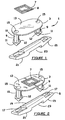
Figure 1 shows an exploded view of an animal tag according to the invention; -
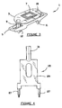
Figure 2 shows an exploded view of an animal tag with transponder secured in place; -
Figure 3 shows the animal tag ofFigure 2 assembled; -
Figure 4 shows a plan view of an implant tool; -
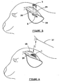
Figure 5 shows the animal tag about to be applied to a sheep's ear; -
Figure 6 shows the animal tag applied to a sheep's ear; -
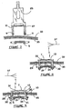
Figure 7 shows a view of the animal tag prior to application to the ear; -
Figure 8 shows the animal tag applied to an ear; -
Figure 9 shows the animal tag applied to an ear after the animal has grown; -
Figure 10 shows an alternative form of animal tag; -
Figure 11 shows the animal tag ofFigure 10 applied to the ear of a cow; -
Figure 12 shows an isometric view of an alternative animal tag assembled; -
Figure 13 shows a plan view of the animal tag ofFigure 12 ; -
Figure 14 shows an isometric view of the penetrating component of the tag ofFigure 12 ; -
Figure 15 shows a side on view of another alternative form of tag; -
Figure 16 shows a plan view of the tag ofFigure 15 ; -
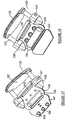
Figures 17 and 18 show isometric views from opposite sides of the tag ofFigure 15 ; -
Figure 19 shows a fragmentary sectional view of the tag ofFigure 15 when assembled; -
Figure 20 shows an isometric view of a tag applied to the ear of a calf or cow; -
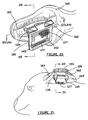
Figure 21 shows an isometric view of a tag applied to the ear of a sheep; -
Figure 22 shows the section 22-22 taken onFigure 21 ; -
Figures 23 and 24 show the sections (23, 24) - (23, 24) taken onFigure 20 for a calf and cow respectively; and -
Figure 25 shows the section 25-25 taken onFigure 20 . - The various elements identified by numerals in the drawings are listed in the following integer list.
-
- 1
- Animal tag
- 3
- Penetrating component
- 5
- Locking component
- 7
- Transponder
- 8
- Coiled antenna
- 9
- Ear penetrating member
- 10
- Tubular portion
- 11
- Ear piercing head
- 12
- Step
- 13
- Joining strip
- 15
- Opening
- 17
- Locking slot
- 19
- Joining portion
- 21
- Ramp
- 23
- Recessed portion
- 25
- Implant tool
- 27
- Implant pin
- 28
- Gap
- 29
- Body
- 30
- Gap
- 31
- Projection
- 32
- Gap
- 33
- Sheep's ear
- 34
- Gap
- 35
- Vascular ridge/vein
- 37
- Aerial
- 50
- Locking component
- 52
- Tubular holder
- 54
- Marker/flag
- 56
- Cow ear
- 57
- Transponder
- 58
- Coil
- 67
- Antenna
- 80
- Animal tag
- 83
- Penetrating component
- 85
- Locking component
- 87
- Transponder cap
- 89
- Ear penetrating member
- 90
- Tubular portion
- 91
- Ear piercing head
- 92
- Step
- 93
- Joining strip
- 94
- Flange
- 95
- Opening
- 97
- Locking slot
- 98
- Cap
- 99
- Joining portion
- 100
- Marker/flag
- 101
- Slot
- 120
- Animal tag
- 123
- Penetrating component
- 125
- Locking component
- 127
- Transponder cap
- 128
- Transponder
- 129
- Ear penetrating member
- 133
- Joining strip
- 138
- Cap
- 139
- Joining portion
- 141
- Slot
- 142
- Slot
- 145
- Marker/flag
- 147
- Cover portion
- 149
- Retainer portion
- 150
- Hinge
- 152
- Recess
- 154
- Projection
- 156
- Socket hole
- 158
- Locater projection
- 160
- Cow ear
- 162
- Vein/vascular ridge
- 163
- Hollow
- 164
- Sheep ear
- 165
- Gap
- 166
- Gap
- 167
- Gap
- 168
- Gap
- Referring to
Figures 1 to 3 , there is shown ananimal tag 1 which comprises a penetratingcomponent 3, alocking component 5 and atransponder 7. - Both the penetrating component and locking component may each be formed of injection moulded plastics material such as thermoplastic polyurethane or polyurethane/rubber.
- The transponder has a coiled
antenna 8 which lies in the plane of the joiningstrip 13 joining the twoear penetrating members 9 on either side of the penetrating component. The joining strip is preferably flexible to permit flexing of the penetrating component to assist with application of the tag and to allow for growth. It is noted that the ear penetrating members are located very close to the opposed edges of the joiningstrip 13 so as to leave little or no scope for an animal to be able to catch the edge under a wire or branch to remove the animal tag. - The transponder may include electronic means for holding and transmitting data to the animal. It may also be capable of being updated with information via an external source such as a radio transmitter.
- Each of the ear penetrating members comprises a
tubular portion 10 with walls having a thickness range generally between 0.2 and 1mm, more preferably 0.4 to 0.8mm. Each of the tubular portions terminates at one end in a join with the joiningstrip 13 leaving anopening 15 for purposes to become apparent. - The other end of the tubular portion in each instance is provided with the
ear piercing head 11 in the form of an arrow head, the join between the tubular portion and arrow head forming astep 12. It can be seen fromFigure 3 that thestep 12 can lock underneath the edges of theramp 21 forming part of the locking component. - The ear piercing heads may include cutting edges of a material such as hardened plastic or steel to assist with pushing the arrow heads through the ear of an animal.
- It should also be noted that the arrow head forming the ear piercing head may have a hexagonal cross section. It may have other alternative cross sectional shapes such as round ellipsoid or polygonal. It may be snap or force fitted through the locking
slots 17 formed in the locking component. - The joining
portion 19 between the two locking slots is raised relative to the height of the locking slots for purposes to become apparent. A recessedportion 23 is formed under the joiningportion 19. - The underneath edges of the locking slots are formed as
ramps 21 which are in the form of wedges, the thicker end of the wedges being nearer the centre of the locking component tapering to a thinner edge towards the outer edges of the locking component. - For this purpose, an
implant tool 25 shown inFigure 4 may be used in association with a tag applicator to apply the tag to the ear of an animal. Applicant's co-pending international applicationPCT/AU02/00508 implant tool 25 includes two implant pins 21 which are shaped so that they can fit snugly through theopenings 15 and into thetubular portions 10 of theear penetrating members 9. - The implant pins serve to hold the ear penetrating members rigid as they might otherwise collapse when they are pressed into the ear of an animal.
- The
implant tool 25 also includes abody 29 joining the two implant pins and aprojection 31 upon which pressure may be exerted to bear down upon the implant pins and hence push the ear piercing heads through the ear. - Referring to
Figures 5 and 6 , it can be seen that the tag is applied to the ear of a sheep closer to the edge of the ear than to the head with the ear penetrating members between and aligned with thevascular ridges 35. By applying the tag in this fashion, it is held in a secure position in a firm manner. The fact that the locking component and the skin penetrating heads are held clear of the vascular ridges serves to reduce the likelihood of inflammation or infection being caused to the animal by attachment of the tag. The radius of the joining portion means that it can act as a spacer and a locator in the hollow between the vascular ridges/veins. - Referring to
Figure 8 , the animal tag is shown after it has been fitted to a sheep'sear 33 with the ear sandwiched between the penetrating component and locking component in a gap between the two broadly designated by the numeral 28. The joiningportion 19 extends in to agap 34 between the inner surface of the ear and the locking component. It has a radius which mimics the curvature of the internal surface of the ear to reduce irritation produced by movement of the tag. Typically, the radius of curvature will lie between 2mm and 9mm. For sheep it may be about 3.5mm and for cattle it may be about 7mm. - It can be seen that the joining
portion 19 because it is raised, sandwiches theear 33 between the penetrating component and locking component leavinglarger gaps 32 between the ear and the lockingslot 17 andsmaller gaps portion 19 and the ear. By designing gaps of this type, there is room for air to contact the small wounds caused by penetration of the ear and hence the rate of healing of the wound can be improved and infection minimised as infection of ears from prior art tagging processes tends to occur on the inside section of the ear. Gap sizes for sheep typically fall within the following ranges:Gap Number Gap Size 28 10 to 24mm Preferably 12mm to 20mm 30 0 to 4mm Preferably 0 to 2mm 32 2 to 16mm Preferably 3mm to 11mm 34 0 to 6mm Preferably 0 to 3mm - Because the coils of the transponder lie parallel to the plane of the joining
strip 13, it is preferred that the orientation of an aerial 37 be parallel to this plane in order to maximise efficiency of transmission between the two. Thus the aerial 37 may typically extend above a race. - Referring to
Figure 9 , the drawing shows the change in appearance of the tag as the animal grows from the size shown inFigure 8 . With normal growth, the thickness of the ear may increase and also the length. This results in theear penetrating members 9 splaying outwards in the manner shown inFigure 9 so that the arrow heads are located at the narrower portion of the wedge orramp 21. This in turn creates agreater clearance 28 between the lockingcomponent 5 and the bottom of the joiningstrip 13 thereby accommodating an increase in the thickness of the ear whilst at the same time accommodating growth in the length of the ear as well. - Because the walls of the tubular portion are relatively thin they can compress and, they will only exert slight resilient pressure to hold the tag in place whilst still allowing sufficient flexibility to accommodate growth in the manner described. The same feature also accommodates different animal sizes in a similar fashion.
- Referring to
Figures 10 and 11 , the alternative form of tag shown therein differs from that in the previous drawings in that thelocking component 50 includes atubular holder 52 attached directly to the locking component. In turn, a marker orflag 54 is attached to the tubular holder. - The tubular holder forms a housing for the
transponder 57 having a coiled antenna with the axis of the coils in line with the axis of the tubular holder. - As can be seen from
Figure 11 , the tag can be applied in a similar manner to that described with reference to the earlier drawings with the marker tubular holder and transponder hanging down from within the ear. Here the tag is applied in a depression between the vascular ridges, on the upper rostral surface of the ear pinna. This form of tag is likely to be more suitable for application to cattle. - Because of the direction of the coils, it is preferred that a vertical aerial running perpendicular to the axis of the coils or in other words parallel to the plane of the coils be used to send signals to the transponder.
- Referring to
Figures 12 to 14 there is shown an alternative construction ofanimal tag 80 in accordance with the invention which comprises a penetratingcomponent 83 and alocking component 85. As in the case of the previously described animal tags, it is expected that both of these components may substantially comprise integral units formed of moulded plastics material. - A
transponder cap 87 may be fitted in abutment with and immediately underneath the joiningstrip 93 of the penetrating component sandwiching a transponder between the two. It may be attached by heat welding, ultrasonic welding, gluing or even by a mechanical snap-fit arrangement. - The broad upper surface of the joining
strip 93 by overlying the transponder protects it and also provides a useful area on which writing or other identification markings and information may be applied in a location where it is readily visible. - The locking component has two
ear penetrating members 89 comprising atubular portion 90 and anear piercing head 91. The ear piercing head forms astep 92 with its join to the tubular portion so that the step may act to lock the penetrating component onto the locking component when the two are pushed together with the ear of an animal sandwiched therebetween. - The ear piercing heads each include two
flanges 94 which act as knife edges to assist the heads to penetrate the ear of an animal. - Each of the ear penetrating members is provided with an
opening 95 allowing access to the interior of thetubular portion 90 for the prongs of an application tool which hold the ear penetrating members rigid when they are pushed through the ear of an animal. - The locking component is provided with two openings for receiving the ear piercing heads 91. Suitably the openings are in the form of locking
slots 97. The width of the locking slots may be slightly less than the maximum width of the ear piercing heads so that the ear piercing heads may be retained in abutment with the edges of the locking slots when the two components are pushed together. - Each of the locking slots is provided with a
cap 98 which surrounds the ear piercing head and hence acts as a "tamper-resistant" feature by preventing access to the ear piercing head after it has been locked in place. This reduces the likelihood that a farmer would transfer the component holding the transponder to another animal. - A joining
portion 99 extends between the two locking slots and associated caps. The joining portion is domed above the level of the locking slots and caps. As a result, it acts as a spacer to create an increased air gap between the ear of an animal and the region where the ear piercing heads have pierced the ear so as to provide good air circulation and thus reduce the incidence of infection. - A marker/
flag 100 is mounted between the two caps and beneath the joiningportion 99. The marker/flag may also include markings for identification, etc. A slot (not shown) may be provided between the marker/flag 100 and joiningportion 99 andslots 101 may be provided on each of the caps. The purpose of these slots is to assist with application by a tag applicator gun. - Referring to
Figures 15 to 19 , there is shown a further version ofanimal tag 120 comprising a penetratingcomponent 123 andlocking component 125. - The animal tag is fitted with a
transponder cap 127 which can be fitted underneath the joiningstrip 133 or in a housing partially defined by therecess 152 in the marker/flag 145. This cap sandwiches atransponder 128 between the transponder cap and joining strip. - As in the previous cases, the penetrating component has two
ear penetrating members 129 fitted with ear piercing heads (not shown), the ear piercing heads being shaped so that they can be driven into and locked within slots (not shown) at the top of thecaps 138. - Adjoining
portion 139 extends between the caps and acts as a spacer in the manner previously described. - Similarly,
slots - The marker/
flag 145 comprises acover portion 147 and aretainer portion 149 joined by ahinge 150. Thus, the cover portion may be bent about the hinge to overlie the retainer portion and close off therecess 152 to form a housing within which the transponder may be retained. -
Projections 154 on the cover portion fit into the socket holes 156 of the retainer portion and may be secured within the holes by conventional means such as heat welding, ultrasonic welding, gluing or mechanical locking. Thus, it is an easy matter to insert a transponder within therecess 152 and to retain the transponder therein by folding over the cover portion and securing it in abutment with the retainer portion. - The cover portion may include
locater projections 158 to assist with holding or locating a transponder held within therecess 152. - Referring to
Figures 20 ,23, 24 and 25 it can be seen that an animal tag along the lines of that described with reference to numeral 120 previously has been applied to theear 160 of a cow. The application of the tag has been to the vertical part of the cow's ear with the marker/flag extending below the level of the ear so as to be visible. - The joining
portion 139 of the tag sits between two of theparallel veins 162 of the ear, the ear penetrating members having also been applied through the region between the twoveins 162. Thus, the domed joiningportion 139 sits in a hollow 163 formed between the vascular ridges/veins and acts as a spacer to allow air to circulate around the wound of the ear caused by the ear penetrating member in the region of the ear piercing head and capsule. Thetransponder 127 may sit within therecess 152 or it may comprise a flat coil sandwiched between the twoportions strip 133 as shown inFigures 15 and 16 . - Referring to
Figures 21 and22 , it can be seen that ananimal tag 120 has been applied to the top of the sheep'sear 164 between twoveins 162 to provide an effective means of animal identification. Whilst the transponder is shown as being retained in the recess, it is to be appreciated that the transponder for the sheep's ear may equally be located beneath the joiningstrip 133. Typically, a higher frequency transponder may be used beneath the joining strip or lower frequency transponder in therecess 152 depending upon the requirements of a user and the radio and other identification equipment available to the user. - It can be seen that the animal tag may adjust as an animal grows from the illustrations in
Figures 23 and 24 . Thus, when the animal is small as shown inFigure 24 , the joiningstrip 133 is bulged and theear penetrating members 129 are angled towards each other. As the animal grows, the ear widens, the bulge flattens and the ear penetrating members assume a parallel configuration as shown inFigure 23 . During the entire growth of the animal, there are range of gaps between the tag and the ear which allow a degree of air circulation and hence assist with healing of the ear after application of the tag. A typical range of gap sizes for a member of the bovine family is shown hereunder.Gap Number Gap Size 165 10mm to 26mm Preferably 12mm to 20mm 166 6mm to 14mm Preferably 8mm to 12mm 167 0mm to 12mm Preferably 4mm to 10mm 168 0mm to 15mm Preferably 0mm to 8mm - Whilst the above description includes the preferred embodiments of the invention, it is to be understood that many variations, alterations, modifications and/or additions may be introduced into the constructions and arrangements of parts previously described without departing from the essential features or the spirit or ambit of the invention.
- It will be also understood that where the word "comprise", and variations such as "comprises" and "comprising", are used in this specification, unless the context requires otherwise such use is intended to imply the inclusion of a stated feature or features but is not to be taken as excluding the presence of other feature or features.
Claims (8)
- An animal tag (1) comprising,
a penetrating component (3) having two ear penetrating members (9) joined by a strip of intermediate material (13),
a complementary component (5) having a locking portion (17) for each ear penetrating member (9), and
a joining portion (19) extending between and joined to the locking portions (17),
characterized in that the ear penetrating members (9) are designed to be passed through the ear (33) of an animal and to lock onto the locking portions (17) to sandwich the ear (33) in a gap (34) between the penetrating component and complementary component and the joining portion extends into the gap (34) so as to provide circulation regions around the two ear penetrating members (9) where the gap (34) is increased in width compared with a region of the gap (34) between the joining portion (19) and the ear (33). - An animal tag according to claim 1 wherein each ear penetrating member (9) comprises a skin penetrating head (11) joined to the strip of intermediate material (13) by a tubular portion (10), the join between each skin penetrating head (9) and tubular portion being formed as shoulder (12) adapted to cooperate with one of the locking portions (17) to lock the penetrating component (3) and complementary component (5) together.
- An animal tag according to claim 2 wherein each skin penetrating head (91) comprises a central supporting portion of moulded plastics material provided with at least two thin flanges (94) extending from the central supporting portion, the at least two thin flanges having sharp edges and meeting at a sharp point forward of the supporting portion.
- An animal tag according to claim 2 or claim 3 wherein each of the locking portions (125) comprises a cap (138) which substantially covers and surrounds each skin penetrating head.
- An animal tag according to any one of claims 1 to 4 wherein the strip of intermediate material (133) comprises plastic material which is sufficiently flexible to be bent from a substantially flat configuration when regions of the ear penetrating members joined to the strip of intermediate material are at their maximum separation to a looped configuration when the regions of the ear penetrating members are squeezed towards each other.
- An animal tag according to any one of claims 1 to 5 having attached thereto any one or more of a flag (54), a transponder (128), any form of data concerning the animal to which the animal tag is attached, any form of diagnostic or electronic device (7, 57, 58), any form of treatment device or chemical, any form of signalling device (7, 57, 58), and any form of locating device.
- An animal tag according to claim 6 having attached thereto a flag (145) and a transponder (127) wherein the transponder comprises a wafer secured beneath the strip of intermediate material and between the two ear penetrating members or the transponder is housed in a housing attached to the flag (145), the housing comprises a first housing component having a recessed portion (152) and a second housing component (147) joined to the first housing component by a hinge (150), whereby the first and second housing components may be folded into overlapping relationship to cover the recess (152) and so form the housing.
- An animal tag according to any one of the preceding claims wherein each locking portion comprises a slot (17) and each ear penetrating member comprises a skin penetrating head (11) for passing through the slot.
Applications Claiming Priority (3)
| Application Number | Priority Date | Filing Date | Title |
|---|---|---|---|
| AU2002952186 | 2002-10-22 | ||
| AU2002952186A AU2002952186A0 (en) | 2002-10-22 | 2002-10-22 | Tagging animals |
| PCT/AU2003/001282 WO2004036984A1 (en) | 2002-10-22 | 2003-09-30 | Tagging animals |
Publications (3)
| Publication Number | Publication Date |
|---|---|
| EP1553821A1 EP1553821A1 (en) | 2005-07-20 |
| EP1553821A4 EP1553821A4 (en) | 2006-04-12 |
| EP1553821B1 true EP1553821B1 (en) | 2008-08-06 |
Family
ID=28047750
Family Applications (1)
| Application Number | Title | Priority Date | Filing Date |
|---|---|---|---|
| EP03809213A Expired - Lifetime EP1553821B1 (en) | 2002-10-22 | 2003-09-30 | Tagging animals |
Country Status (10)
| Country | Link |
|---|---|
| US (1) | US7690141B2 (en) |
| EP (1) | EP1553821B1 (en) |
| CN (1) | CN1688189A (en) |
| AT (1) | ATE403373T1 (en) |
| AU (1) | AU2002952186A0 (en) |
| BR (1) | BR0315518A (en) |
| CA (1) | CA2501776C (en) |
| DE (1) | DE60322730D1 (en) |
| NZ (1) | NZ539462A (en) |
| WO (1) | WO2004036984A1 (en) |
Families Citing this family (32)
| Publication number | Priority date | Publication date | Assignee | Title |
|---|---|---|---|---|
| BE1016247A5 (en) * | 2004-10-25 | 2006-06-06 | Wijk Anton Van | IDENTIFICATION DEVICE AND METHOD FOR MANUFACTURING IT |
| US7837612B2 (en) * | 2005-04-08 | 2010-11-23 | Ethicon Endo-Surgery, Inc. | Tissue suspension device |
| DE102005018402B4 (en) * | 2005-04-20 | 2009-10-01 | Gea Westfaliasurge Gmbh | Diagnostic method and diagnostic device for an animal identification system, in particular an animal identification system of a milking installation and milking installation with an animal identification system |
| ES2298016B1 (en) * | 2006-01-10 | 2009-07-21 | Rumitag, S.L. | LABEL LABEL FOR THE IDENTIFICATION OF ANIMALS. |
| FR2926005B1 (en) * | 2008-01-08 | 2010-03-05 | Affflex Europ | AURICULAR LOOP FOR MARKING PROMOTING HEALING |
| EP2476308A2 (en) * | 2009-08-12 | 2012-07-18 | Carlos Alberto Barcelo Rojas | Bioelectronic system |
| NZ588486A (en) * | 2009-10-08 | 2012-04-27 | Gold Rythmn Pty Ltd | Improvements in animal tags |
| CN101763524B (en) * | 2009-12-31 | 2016-05-18 | 上海量科电子科技有限公司 | Direction controlled electronic tag transmitting block |
| JP5794675B2 (en) * | 2011-06-01 | 2015-10-14 | キヤノン株式会社 | Display board mounting structure, pan head device and camera device |
| US20130072954A1 (en) * | 2011-09-17 | 2013-03-21 | Jose C. Suarez | Umbilical Locator |
| CA2848820A1 (en) * | 2011-11-30 | 2013-06-06 | Illinois Tool Works Inc. | Remote monitoring systems |
| CA2880093C (en) | 2012-07-26 | 2019-01-08 | Enduro Tags Pty Ltd | An animal tag including a transponder casing housed in a cartridge |
| US9167801B2 (en) * | 2012-09-24 | 2015-10-27 | Y-Tex Corporation | Insecticide strip and combination with identification ear tag |
| DE102013100987B4 (en) * | 2013-01-31 | 2023-06-29 | Phoenix Contact Gmbh & Co. Kg | connection module |
| US11071279B2 (en) | 2014-09-05 | 2021-07-27 | Intervet Inc. | Method and system for tracking health in animal populations |
| US10986817B2 (en) | 2014-09-05 | 2021-04-27 | Intervet Inc. | Method and system for tracking health in animal populations |
| WO2016168886A1 (en) * | 2015-04-24 | 2016-10-27 | Enduro Tags Pty Ltd | Animal tag |
| AT15109U1 (en) * | 2015-04-30 | 2017-01-15 | Smartbow Gmbh | Multi-part ear tag for an animal |
| FR3054408B1 (en) * | 2016-07-27 | 2019-07-12 | Allflex Europe | FEMALE PART OF ANIMAL IDENTIFICATION DEVICE COMPRISING A BLOCKING MEMBER OF THE MALE PART IN THE FEMALE PART |
| USD853664S1 (en) * | 2017-08-30 | 2019-07-09 | Craig E. Ritchey | Ear tag component |
| US20210212288A1 (en) * | 2018-05-17 | 2021-07-15 | Ceres Tag Pty Ltd | Animal tag |
| USD947468S1 (en) | 2018-05-23 | 2022-03-29 | Craig E. Ritchey | Ear tag component |
| US10847062B2 (en) * | 2018-10-18 | 2020-11-24 | BM GROUP HOLDING S.p.A. | Tag for bundles of metal products obtained from respective iron and steel processes |
| CN109916535B (en) * | 2019-03-12 | 2021-05-18 | 于晓宇 | Livestock eardrum temperature measuring device |
| CN109769709B (en) * | 2019-03-12 | 2021-08-31 | 于晓宇 | Livestock ear tag installation guide |
| CN111436381B (en) * | 2020-04-28 | 2021-11-19 | 深圳市溯安智能科技有限公司 | Improved stable label injection handheld gun |
| CN114097641A (en) * | 2020-08-27 | 2022-03-01 | 卡尤迪智农科技(北京)有限公司 | Animal tag |
| CN113229167A (en) * | 2021-06-04 | 2021-08-10 | 重庆御芯微信息技术有限公司 | Intelligent ear tag for pigs |
| CN114973919B (en) * | 2022-05-17 | 2024-04-05 | 南京中睿安智能科技有限公司 | Identification device for multiple scenes |
| CN114902973B (en) * | 2022-05-30 | 2023-11-17 | 四川御智微科技有限公司 | Novel animal ear tag |
| US12616169B2 (en) * | 2023-12-21 | 2026-05-05 | 701x Inc. | Livestock ear tag system |
| USD1062098S1 (en) * | 2024-09-23 | 2025-02-11 | Shen Li | Ear tag |
Family Cites Families (17)
| Publication number | Priority date | Publication date | Assignee | Title |
|---|---|---|---|---|
| US1376223A (en) * | 1919-11-14 | 1921-04-26 | Arthur A Pannier | Ear-tag |
| US1390342A (en) * | 1920-10-14 | 1921-09-13 | Delay Eugene | Cattle-mark |
| FR2141806A1 (en) * | 1971-06-18 | 1973-01-26 | Marosi Angelo De | |
| US3958353A (en) * | 1974-04-29 | 1976-05-25 | Hayes Norman J | Two piece animal identification tag assembly |
| NZ176913A (en) | 1975-03-12 | 1978-06-02 | Delta Plastics Ltd | Animal ear tag:resilient tab with spike and hole |
| FR2368219A1 (en) * | 1976-10-21 | 1978-05-19 | Roulon Paul | Animal ear tag permitting continual identification - comprises male plate with two heads engaging openings in female plate and including engraved numeral protected against wear by raised edge |
| US4425726A (en) * | 1982-03-18 | 1984-01-17 | Dvorak Edward E | Ear tag for animals |
| NZ212275A (en) * | 1985-06-11 | 1989-07-27 | Allflex Int | Ear tag with cavity for electronic device |
| NL9101468A (en) * | 1991-08-30 | 1993-03-16 | Texas Instruments Holland | Earmark |
| NL9300289A (en) * | 1992-09-21 | 1994-04-18 | Nedap Nv | Loss, flame and fraud resistant electronic identification label. |
| GB9226761D0 (en) * | 1992-12-23 | 1993-02-17 | Potts Christopher | A dispensing device for applying two-part tags |
| US5461807A (en) * | 1994-04-13 | 1995-10-31 | Fearing Manufacturing Company | Animal eartag electronic transponder |
| DE29511183U1 (en) * | 1995-07-18 | 1996-11-14 | Diehl Ident Gmbh | Transponder ear tag |
| DE29706633U1 (en) | 1997-04-08 | 1998-08-06 | Diehl Ident Gmbh | Electronically identifiable ear tag |
| ATE235806T1 (en) | 1997-12-09 | 2003-04-15 | Allflex New Zealand | EARTAG FOR ANIMALS |
| US6145225A (en) | 1998-07-02 | 2000-11-14 | Ritchey; Eugene B. | Animal ear tag assembly and component locking member |
| US6055752A (en) * | 1998-07-02 | 2000-05-02 | Ritchey; Eugene B. | Ear tag with locking member for multi-purpose storage |
-
2002
- 2002-10-22 AU AU2002952186A patent/AU2002952186A0/en not_active Abandoned
-
2003
- 2003-09-30 BR BR0315518-8A patent/BR0315518A/en not_active IP Right Cessation
- 2003-09-30 CN CNA038245108A patent/CN1688189A/en active Pending
- 2003-09-30 NZ NZ539462A patent/NZ539462A/en not_active IP Right Cessation
- 2003-09-30 EP EP03809213A patent/EP1553821B1/en not_active Expired - Lifetime
- 2003-09-30 DE DE60322730T patent/DE60322730D1/en not_active Expired - Lifetime
- 2003-09-30 CA CA2501776A patent/CA2501776C/en not_active Expired - Fee Related
- 2003-09-30 US US10/532,189 patent/US7690141B2/en not_active Expired - Fee Related
- 2003-09-30 WO PCT/AU2003/001282 patent/WO2004036984A1/en not_active Ceased
- 2003-09-30 AT AT03809213T patent/ATE403373T1/en not_active IP Right Cessation
Also Published As
| Publication number | Publication date |
|---|---|
| US20060047287A1 (en) | 2006-03-02 |
| BR0315518A (en) | 2005-08-23 |
| AU2002952186A0 (en) | 2002-10-31 |
| CA2501776C (en) | 2012-01-17 |
| CN1688189A (en) | 2005-10-26 |
| US7690141B2 (en) | 2010-04-06 |
| EP1553821A1 (en) | 2005-07-20 |
| NZ539462A (en) | 2005-12-23 |
| WO2004036984A1 (en) | 2004-05-06 |
| DE60322730D1 (en) | 2008-09-18 |
| CA2501776A1 (en) | 2004-05-06 |
| ATE403373T1 (en) | 2008-08-15 |
| EP1553821A4 (en) | 2006-04-12 |
Similar Documents
| Publication | Publication Date | Title |
|---|---|---|
| CA2501776C (en) | Tagging animals | |
| US11553695B2 (en) | Single or dual technology animal tags and system and method of using the same | |
| US4612877A (en) | Multiple purpose animal ear tag system | |
| US4718374A (en) | Animal ear tag and identification system | |
| US4750284A (en) | Tag assemblies | |
| US4785563A (en) | Animal tag microfiche indentification system | |
| US6708432B2 (en) | Temper evident ear tag system | |
| US5526772A (en) | Electronic identification tagging method for food-producing animals | |
| EP0187807B1 (en) | A marking element for marking animals or the like | |
| AU2003265730B2 (en) | Tagging animals | |
| WO1985004551A1 (en) | Animal identification | |
| WO2006019316A1 (en) | Animal ear tag | |
| KR100687082B1 (en) | Pig hysteresis tag with RFID chip | |
| AU540308B2 (en) | Improvements in animal ear tags | |
| NZ216931A (en) | Animal eartag assembly | |
| HK40060953A (en) | Tag system for tracking an animal | |
| HK1261235B (en) | Single or dual technology animal tags and system and method of using the same | |
| HK1261235A1 (en) | Single or dual technology animal tags and system and method of using the same |
Legal Events
| Date | Code | Title | Description |
|---|---|---|---|
| PUAI | Public reference made under article 153(3) epc to a published international application that has entered the european phase |
Free format text: ORIGINAL CODE: 0009012 |
|
| 17P | Request for examination filed |
Effective date: 20050413 |
|
| AK | Designated contracting states |
Kind code of ref document: A1 Designated state(s): AT BE BG CH CY CZ DE DK EE ES FI FR GB GR HU IE IT LI LU MC NL PT RO SE SI SK TR |
|
| AX | Request for extension of the european patent |
Extension state: AL LT LV MK |
|
| DAX | Request for extension of the european patent (deleted) | ||
| A4 | Supplementary search report drawn up and despatched |
Effective date: 20060224 |
|
| 17Q | First examination report despatched |
Effective date: 20060823 |
|
| GRAP | Despatch of communication of intention to grant a patent |
Free format text: ORIGINAL CODE: EPIDOSNIGR1 |
|
| GRAS | Grant fee paid |
Free format text: ORIGINAL CODE: EPIDOSNIGR3 |
|
| GRAA | (expected) grant |
Free format text: ORIGINAL CODE: 0009210 |
|
| AK | Designated contracting states |
Kind code of ref document: B1 Designated state(s): AT BE BG CH CY CZ DE DK EE ES FI FR GB GR HU IE IT LI LU MC NL PT RO SE SI SK TR |
|
| REG | Reference to a national code |
Ref country code: GB Ref legal event code: FG4D |
|
| REG | Reference to a national code |
Ref country code: CH Ref legal event code: EP |
|
| REG | Reference to a national code |
Ref country code: IE Ref legal event code: FG4D |
|
| REF | Corresponds to: |
Ref document number: 60322730 Country of ref document: DE Date of ref document: 20080918 Kind code of ref document: P |
|
| REG | Reference to a national code |
Ref country code: SE Ref legal event code: TRGR |
|
| REG | Reference to a national code |
Ref country code: GR Ref legal event code: EP Ref document number: 20080403003 Country of ref document: GR |
|
| PG25 | Lapsed in a contracting state [announced via postgrant information from national office to epo] |
Ref country code: ES Free format text: LAPSE BECAUSE OF FAILURE TO SUBMIT A TRANSLATION OF THE DESCRIPTION OR TO PAY THE FEE WITHIN THE PRESCRIBED TIME-LIMIT Effective date: 20081117 |
|
| PG25 | Lapsed in a contracting state [announced via postgrant information from national office to epo] |
Ref country code: SI Free format text: LAPSE BECAUSE OF FAILURE TO SUBMIT A TRANSLATION OF THE DESCRIPTION OR TO PAY THE FEE WITHIN THE PRESCRIBED TIME-LIMIT Effective date: 20080806 Ref country code: FI Free format text: LAPSE BECAUSE OF FAILURE TO SUBMIT A TRANSLATION OF THE DESCRIPTION OR TO PAY THE FEE WITHIN THE PRESCRIBED TIME-LIMIT Effective date: 20080806 Ref country code: AT Free format text: LAPSE BECAUSE OF FAILURE TO SUBMIT A TRANSLATION OF THE DESCRIPTION OR TO PAY THE FEE WITHIN THE PRESCRIBED TIME-LIMIT Effective date: 20080806 |
|
| PG25 | Lapsed in a contracting state [announced via postgrant information from national office to epo] |
Ref country code: BE Free format text: LAPSE BECAUSE OF FAILURE TO SUBMIT A TRANSLATION OF THE DESCRIPTION OR TO PAY THE FEE WITHIN THE PRESCRIBED TIME-LIMIT Effective date: 20080806 |
|
| PG25 | Lapsed in a contracting state [announced via postgrant information from national office to epo] |
Ref country code: DK Free format text: LAPSE BECAUSE OF FAILURE TO SUBMIT A TRANSLATION OF THE DESCRIPTION OR TO PAY THE FEE WITHIN THE PRESCRIBED TIME-LIMIT Effective date: 20080806 Ref country code: BG Free format text: LAPSE BECAUSE OF FAILURE TO SUBMIT A TRANSLATION OF THE DESCRIPTION OR TO PAY THE FEE WITHIN THE PRESCRIBED TIME-LIMIT Effective date: 20081106 Ref country code: MC Free format text: LAPSE BECAUSE OF NON-PAYMENT OF DUE FEES Effective date: 20080930 |
|
| PG25 | Lapsed in a contracting state [announced via postgrant information from national office to epo] |
Ref country code: RO Free format text: LAPSE BECAUSE OF FAILURE TO SUBMIT A TRANSLATION OF THE DESCRIPTION OR TO PAY THE FEE WITHIN THE PRESCRIBED TIME-LIMIT Effective date: 20080806 Ref country code: SK Free format text: LAPSE BECAUSE OF FAILURE TO SUBMIT A TRANSLATION OF THE DESCRIPTION OR TO PAY THE FEE WITHIN THE PRESCRIBED TIME-LIMIT Effective date: 20080806 Ref country code: PT Free format text: LAPSE BECAUSE OF FAILURE TO SUBMIT A TRANSLATION OF THE DESCRIPTION OR TO PAY THE FEE WITHIN THE PRESCRIBED TIME-LIMIT Effective date: 20090106 Ref country code: CZ Free format text: LAPSE BECAUSE OF FAILURE TO SUBMIT A TRANSLATION OF THE DESCRIPTION OR TO PAY THE FEE WITHIN THE PRESCRIBED TIME-LIMIT Effective date: 20080806 |
|
| PLBE | No opposition filed within time limit |
Free format text: ORIGINAL CODE: 0009261 |
|
| STAA | Information on the status of an ep patent application or granted ep patent |
Free format text: STATUS: NO OPPOSITION FILED WITHIN TIME LIMIT |
|
| 26N | No opposition filed |
Effective date: 20090507 |
|
| PG25 | Lapsed in a contracting state [announced via postgrant information from national office to epo] |
Ref country code: EE Free format text: LAPSE BECAUSE OF FAILURE TO SUBMIT A TRANSLATION OF THE DESCRIPTION OR TO PAY THE FEE WITHIN THE PRESCRIBED TIME-LIMIT Effective date: 20080806 |
|
| PG25 | Lapsed in a contracting state [announced via postgrant information from national office to epo] |
Ref country code: IT Free format text: LAPSE BECAUSE OF FAILURE TO SUBMIT A TRANSLATION OF THE DESCRIPTION OR TO PAY THE FEE WITHIN THE PRESCRIBED TIME-LIMIT Effective date: 20080806 |
|
| PG25 | Lapsed in a contracting state [announced via postgrant information from national office to epo] |
Ref country code: HU Free format text: LAPSE BECAUSE OF FAILURE TO SUBMIT A TRANSLATION OF THE DESCRIPTION OR TO PAY THE FEE WITHIN THE PRESCRIBED TIME-LIMIT Effective date: 20090207 Ref country code: LU Free format text: LAPSE BECAUSE OF NON-PAYMENT OF DUE FEES Effective date: 20080930 Ref country code: CY Free format text: LAPSE BECAUSE OF FAILURE TO SUBMIT A TRANSLATION OF THE DESCRIPTION OR TO PAY THE FEE WITHIN THE PRESCRIBED TIME-LIMIT Effective date: 20080806 |
|
| PG25 | Lapsed in a contracting state [announced via postgrant information from national office to epo] |
Ref country code: TR Free format text: LAPSE BECAUSE OF FAILURE TO SUBMIT A TRANSLATION OF THE DESCRIPTION OR TO PAY THE FEE WITHIN THE PRESCRIBED TIME-LIMIT Effective date: 20080806 |
|
| PGFP | Annual fee paid to national office [announced via postgrant information from national office to epo] |
Ref country code: CH Payment date: 20111012 Year of fee payment: 9 |
|
| PGFP | Annual fee paid to national office [announced via postgrant information from national office to epo] |
Ref country code: SE Payment date: 20120919 Year of fee payment: 10 Ref country code: IE Payment date: 20120920 Year of fee payment: 10 |
|
| PGFP | Annual fee paid to national office [announced via postgrant information from national office to epo] |
Ref country code: GR Payment date: 20120926 Year of fee payment: 10 |
|
| PGFP | Annual fee paid to national office [announced via postgrant information from national office to epo] |
Ref country code: FR Payment date: 20121010 Year of fee payment: 10 |
|
| REG | Reference to a national code |
Ref country code: CH Ref legal event code: PL |
|
| REG | Reference to a national code |
Ref country code: GR Ref legal event code: ML Ref document number: 20080403003 Country of ref document: GR Effective date: 20140403 |
|
| REG | Reference to a national code |
Ref country code: SE Ref legal event code: EUG |
|
| REG | Reference to a national code |
Ref country code: FR Ref legal event code: ST Effective date: 20140530 |
|
| REG | Reference to a national code |
Ref country code: IE Ref legal event code: MM4A |
|
| PG25 | Lapsed in a contracting state [announced via postgrant information from national office to epo] |
Ref country code: LI Free format text: LAPSE BECAUSE OF NON-PAYMENT OF DUE FEES Effective date: 20130930 Ref country code: CH Free format text: LAPSE BECAUSE OF NON-PAYMENT OF DUE FEES Effective date: 20130930 Ref country code: IE Free format text: LAPSE BECAUSE OF NON-PAYMENT OF DUE FEES Effective date: 20130930 |
|
| PG25 | Lapsed in a contracting state [announced via postgrant information from national office to epo] |
Ref country code: GR Free format text: LAPSE BECAUSE OF NON-PAYMENT OF DUE FEES Effective date: 20140403 Ref country code: FR Free format text: LAPSE BECAUSE OF NON-PAYMENT OF DUE FEES Effective date: 20130930 Ref country code: SE Free format text: LAPSE BECAUSE OF NON-PAYMENT OF DUE FEES Effective date: 20131001 |
|
| PGFP | Annual fee paid to national office [announced via postgrant information from national office to epo] |
Ref country code: GB Payment date: 20150917 Year of fee payment: 13 Ref country code: DE Payment date: 20150922 Year of fee payment: 13 |
|
| PGFP | Annual fee paid to national office [announced via postgrant information from national office to epo] |
Ref country code: NL Payment date: 20150917 Year of fee payment: 13 |
|
| REG | Reference to a national code |
Ref country code: DE Ref legal event code: R119 Ref document number: 60322730 Country of ref document: DE |
|
| REG | Reference to a national code |
Ref country code: NL Ref legal event code: MM Effective date: 20161001 |
|
| GBPC | Gb: european patent ceased through non-payment of renewal fee |
Effective date: 20160930 |
|
| PG25 | Lapsed in a contracting state [announced via postgrant information from national office to epo] |
Ref country code: NL Free format text: LAPSE BECAUSE OF NON-PAYMENT OF DUE FEES Effective date: 20161001 |
|
| PG25 | Lapsed in a contracting state [announced via postgrant information from national office to epo] |
Ref country code: GB Free format text: LAPSE BECAUSE OF NON-PAYMENT OF DUE FEES Effective date: 20160930 Ref country code: DE Free format text: LAPSE BECAUSE OF NON-PAYMENT OF DUE FEES Effective date: 20170401 |