JP5794675B2 - Display board mounting structure, pan head device and camera device - Google Patents
Display board mounting structure, pan head device and camera device Download PDFInfo
- Publication number
- JP5794675B2 JP5794675B2 JP2011123463A JP2011123463A JP5794675B2 JP 5794675 B2 JP5794675 B2 JP 5794675B2 JP 2011123463 A JP2011123463 A JP 2011123463A JP 2011123463 A JP2011123463 A JP 2011123463A JP 5794675 B2 JP5794675 B2 JP 5794675B2
- Authority
- JP
- Japan
- Prior art keywords
- display
- shaft
- engagement
- mounting structure
- display board
- Prior art date
- Legal status (The legal status is an assumption and is not a legal conclusion. Google has not performed a legal analysis and makes no representation as to the accuracy of the status listed.)
- Active
Links
Images


Classifications
-
- G—PHYSICS
- G09—EDUCATION; CRYPTOGRAPHY; DISPLAY; ADVERTISING; SEALS
- G09F—DISPLAYING; ADVERTISING; SIGNS; LABELS OR NAME-PLATES; SEALS
- G09F7/00—Signs, name or number plates, letters, numerals, or symbols; Panels or boards
- G09F7/02—Signs, plates, panels or boards using readily-detachable elements bearing or forming symbols
- G09F7/06—Signs, plates, panels or boards using readily-detachable elements bearing or forming symbols the elements being secured or adapted to be secured by means of pins and holes
-
- Y—GENERAL TAGGING OF NEW TECHNOLOGICAL DEVELOPMENTS; GENERAL TAGGING OF CROSS-SECTIONAL TECHNOLOGIES SPANNING OVER SEVERAL SECTIONS OF THE IPC; TECHNICAL SUBJECTS COVERED BY FORMER USPC CROSS-REFERENCE ART COLLECTIONS [XRACs] AND DIGESTS
- Y10—TECHNICAL SUBJECTS COVERED BY FORMER USPC
- Y10T—TECHNICAL SUBJECTS COVERED BY FORMER US CLASSIFICATION
- Y10T403/00—Joints and connections
- Y10T403/70—Interfitted members
- Y10T403/7005—Lugged member, rotary engagement
Landscapes
- Physics & Mathematics (AREA)
- General Physics & Mathematics (AREA)
- Engineering & Computer Science (AREA)
- Theoretical Computer Science (AREA)
- Accessories Of Cameras (AREA)
- Connection Of Plates (AREA)
Description
本発明は、表示板の取付け構造に関し、特に2つ以上の姿勢で設置する雲台装置等の機器への表示板の取付け構造並びに雲台装置及びカメラ装置に関するものである。 The present invention relates to a display plate mounting structure, and more particularly to a display plate mounting structure for a device such as a pan head device installed in two or more postures, a pan head device, and a camera device.
従来、雲台装置において、筐体外装面にメーカーロゴを表示したものが知られている。このような雲台装置は、正立姿勢以外にも、天吊り姿勢で設置されることがあるので、これに伴い、表示も設置姿勢に応じた向きで視認されることが望ましい。
例えば、特許文献1では、表示板の裏面に引っ掛け部が設けられた軸を突設させ、板状の部分に設けられた孔に軸を挿通し、軸の引っ掛け部にバネ部材を取付け、表示板を軸方向に付勢し、板状の部分の孔に対し回転調整可能に取り付ける構造が開示されている。
2. Description of the Related Art Conventionally, in a pan head device, a maker logo displayed on a case exterior surface is known. Since such a pan head apparatus may be installed in a ceiling-suspended posture in addition to the upright posture, it is desirable that the display is visually recognized in a direction corresponding to the installation posture.
For example, in
また、特許文献2では、表示板の取付け面に凹部を設け、表示板を外すときに表示板を押し込むと凹部に表示板が沈み込んで反対側の面を起き上がらせ、表示板を取り外すことが出来、表示姿勢を変更して取付けすることが出来る構造が開示されている。
Further, in
しかしながら、上述の特許文献1に開示された従来技術では、表示板を回転調整可能に取り付けるためにバネ部材が必要で部品点数が増えてしまう。また特許文献2に開示された従来技術では、製品毎に表示板の取付け面は変化するので、表示板は製品毎に形状を変える必要があり、かつ、180度毎の姿勢にしか対応することが出来ない。
However, in the prior art disclosed in
そこで、本発明の目的は、簡素な構成で、さまざまな面形状の機器の設置姿勢に応じた表示板の取付けを可能にした表示板の取り付け構造を提供することである。 Accordingly, an object of the present invention is to provide a display plate mounting structure that enables a display plate to be mounted in accordance with the installation postures of devices having various surface shapes with a simple configuration.
上記目的を達成するために、本発明は、機器の筺体と、弾性体で形成される表示板であって少なくとも2つ以上の姿勢で前記筐体外装面に取付けることができる表示板と、を備える表示板の取付け構造であって、前記表示板は、表示面に対して裏側の面に突設された軸であってその先端に係止爪を備える軸と、少なくとも2つの係合片であってそれぞれが鍵状突起を有する係合片と、前記係合片が設けられている側の前記表示面の裏面の端部に少なくとも2つの切り欠きと、を備え、前記筐体外装面は、前記軸が挿通される支持孔と、前記少なくとも2つの係合片と係合する少なくとも2つの係合孔とを備え、前記軸が前記支持孔に挿通されると、前記係止爪は前記表示板の前記軸の延在する方向への動きを規制し、前記少なくとも2つの係合片が前記少なくとも2つの係合孔に挿通されると前記鍵状突起と前記少なくとも2つの係合孔が係合し、前記表示板が前記筐体外装面に装着され、前記少なくとも2つの係合片は、前記表示板の長手方向と直交する方向に分割して構成される、ことを特徴とする。 In order to achieve the above object, the present invention provides a device housing and a display plate formed of an elastic body, which can be attached to the housing exterior surface in at least two postures. A display board mounting structure, wherein the display board is a shaft projecting from a surface on the back side of the display surface, the shaft having a locking claw at the tip thereof, and at least two engagement pieces. Each having a key-like protrusion, and at least two cutouts on the back surface of the display surface on the side where the engagement piece is provided, A support hole through which the shaft is inserted, and at least two engagement holes engaged with the at least two engagement pieces, and when the shaft is inserted into the support hole, The movement of the display board in the extending direction of the shaft is restricted, and the at least two Pieces are at least two said to be inserted into the engaging hole and the hook-shaped projection at least two engaging holes are engaged, the panel is mounted to the housing exterior surface, said at least two engagement The piece is configured by being divided in a direction perpendicular to the longitudinal direction of the display panel .
本発明によれば、簡素な構成で、さまざまな面形状の機器の設置姿勢に応じた表示板の取付けをすることができる。 According to the present invention, it is possible to attach the display board according to the installation postures of devices having various surface shapes with a simple configuration.
以下に、本発明の好ましい実施の形態を、添付の図面に基づいて詳細に説明する。 Hereinafter, preferred embodiments of the present invention will be described in detail with reference to the accompanying drawings.
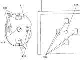
以下、図1から図9を参照して、本発明の第1の実施例による、表示板の取付け構造について説明する。図1は、本発明の実施形態に係る、表示板の取付け構造を備えた雲台装置の斜視図を示している。図示しない三脚等により支持された台座1には、ヘッド2が水平方向に回動自在に取り付けられ、このヘッド2には撮影装置が搭載されたハウジング3が垂直方向において回動自在に取り付けられている。台座1には、情報や絵、形などの方向性を有する表示部zが備わっている。台座1、ヘッド2、ハウジング3およびハウジング3に搭載された撮影装置によりカメラ装置が構成されている。
A display panel mounting structure according to a first embodiment of the present invention will be described below with reference to FIGS. FIG. 1 is a perspective view of a pan / tilt head device having a display plate mounting structure according to an embodiment of the present invention. A
図2は図1をY視方向から見た表示部zの分解斜視図、図3は図2の構成を台座1の内部から見た、表示部zの分解斜視図、図4は図1のX−X方向から見た断面図である。表示部zは、表示板4と、表示板4を回転自在に収容する収容部5により構成されている。図3で示されるように、表示板4には、表示がなされている面である表示面の裏側の面の、略中央に突設される軸であって、その先端に鍵状の係止爪4A1を備える軸4Aが形成され、軸4A回りに対称に、鍵状突起4Bが形成された係合片4Cを2箇所備え、ゴム、シリコンゴム、プラスチック等(以下、ゴム等と記す)の弾性体で形成されている。収容部5は、軸4Aが挿通して回転可能に支持する支持孔5Aと、係合片4Cが挿通する2箇所の係合孔5Bを備える。図4より、表示板4が、収容部5に装着されている時の状態を説明する。表示板4の軸4Aが、支持孔5Aに挿通されると、係止爪4A1により表示板4の軸が延在する方向(軸方向)への動きが規制される。さらに係合片4Cが係合孔5Bに挿通されると、表示板4の弾性力により、鍵状突起4Bが係合孔5Bの縁部に対して付勢された状態で鍵状突起4Bが係合孔5Bと係合する。このことにより、表示板4は、台座1の面に形状をならいながら、収容部5に装着される。
2 is an exploded perspective view of the display unit z when FIG. 1 is viewed from the Y viewing direction, FIG. 3 is an exploded perspective view of the display unit z when the configuration of FIG. 2 is viewed from the inside of the
図4から図7を参照して、表示板4の姿勢を変更する方法について説明する。図6は、雲台装置が天吊り設置状態の図である。この状態のときは、表示部zが雲台装置にならって天地逆転して視認しづらい向きになる。図4で示すように、表示板4の端部4D1に力F1と、端部4D2に力F2を加え、弾性変形させることで、鍵状突起4Bの係止が解除され、係合片4Cが係合孔5Bより抜ける。図5は、係合片4Cが係合孔5Bより抜けた状態を表す図である。この状態のとき表示板4は、図7で示されるように、軸4Aを中心に回転可能となり、表示が視認しやすい向きへ回転させ、再度収容部5へ装着することが可能となる。上記の動作を行うことで、雲台装置の設置姿勢に合わせて、表示板4の姿勢を変えて装着することが可能となる。
A method for changing the posture of the
このように本実施例において、情報や絵、形などの方向性を有する表示板4を、弾性変形可能なゴム等の弾性体によって形成した。また収容部5において軸4Aを中心に回転可能に支持され、表示部zを備える台座1の面形状にならって取付けられるように、鍵状突起4Bが形成された係合片4Cを設けた。
As described above, in this embodiment, the
本実施形態の効果として、表示板4をゴム等の弾性体で形成し、係合片4Cを係合孔5Bより挿脱可能に構成したので、一旦表示の向きを決めて台座1に取り付けた後でも、雲台装置の設置姿勢に応じて、表示板の姿勢を変えることが可能となる。また表示板4が弾性変形することで、さまざまな面形状にならうことが出来る。よって異なる表面形状の機器に対しても、一つの表示板4で対応することが出来、表示板としての部品を共通化することが出来る。
As an effect of the present embodiment, the
また、図3で示されるように、表示板4の係合片が設けられている側の、表示面の裏面の端部に切り欠き4Eを設けてもよい。切り欠き4Eを設けることで、端部4D1と4D2に力F1、F2を作用させることが容易となり、上述の効果に加えて、収容部5からの挿脱が迅速かつ簡単に行うことが可能となる。
In addition, as shown in FIG. 3, a
また図8で示されるように、表示板4の係合片4Cを、係合片4C1のように中央部を切り欠いた形状にしてもよい。すなわち、表示板4の長手方向における両端側に設けられた係合片4Cを、長手方向と直交する方向である横方向に分割された複数の係合片からなる(横方向に延在する構成部分を有さない)係合片4C1としてもよい。係合片をこのように構成することで、表示板4の長手方向における両端側に設けられた係合片4C1によって、長手方向と垂直な方向である横方向(すなわち、図8中に示す矢印方向)に曲率を付するような曲げに対して剛性を高めることなく、雲台装置等の筐体装着部の横方向の曲面にもならって表示板4を装着することが出来る。
Further, as shown in FIG. 8, the
なお、表示板の筐体外装面側の面の曲率半径をR1、表示板を取り付ける筐体外装面の装着面の曲率半径をR2としたとき、以下の関係を満足するとなお好ましい。表示板の筐体外装面側の面が表示面(取り付け側とは反対側の面)側に凸となる場合のR1の符号を正、装着面が表示板側に凸となる場合のR2の符号を正としたとき、
R1×R2>0、かつ、R1>R2 (1)
R1<0、かつ、R2>0 (2)
取付ける装着面が平面、かつ、R1<0 (3)
のいずれかを満足するように設定すると好ましい。
It is more preferable that the following relationship is satisfied, where R1 is the radius of curvature of the surface of the display panel on the casing exterior surface side and R2 is the curvature radius of the mounting surface of the casing exterior surface to which the display panel is attached. The sign of R1 when the surface on the housing exterior surface side of the display board is convex on the display surface (the surface opposite to the mounting side) is positive, and the sign of R2 when the mounting surface is convex on the display board side. When the sign is positive,
R1 × R2> 0 and R1> R2 (1)
R1 <0 and R2> 0 (2)
The mounting surface to be installed is flat and R1 <0 (3)
It is preferable to set so that either of the above is satisfied.
この条件を満足するように、表示板4の筐体外装面側の面の曲率半径R1と、表示板4を取付ける筐体外装面の装着面の曲率半径R2を設定することで、表示板を構成する材料の弾性による復元力により、表示板4を装着面に装着したときに、軸4Aの反対側(反対方向)を向くように構成されている係合片4Cの鍵状突起4Bが係合孔5Bに対し、軸4Aの反対側(反対方向)に働く付勢力(図9中の楕円で示した部分おける矢印で記載される力)を持って係合するため、表示板4が取付け部に遊びを有することなく安定して装着することができる。
In order to satisfy this condition, by setting the curvature radius R1 of the surface of the
また、本実施例では、表示板4の係合片4Cの鍵状突起4Bは、軸4Aに対し反対側を向くように構成されている形態として例示したが、本発明はこれに限定されることはない。表示板4の係合片4Cの鍵状突起4Bが、軸4Aの側を向くように構成してもよい。この場合は、
R1×R2>0、かつ、R1<R2 (4)
R1>0、かつ、R2<0 (5)
取付ける装着面が平面、かつ、R1>0 (6)
のいずれかを満足するように設定すると好ましい。
Further, in this embodiment, the key-
R1 × R2> 0 and R1 <R2 (4)
R1> 0 and R2 <0 (5)
The mounting surface to be installed is flat and R1> 0 (6)
It is preferable to set so that either of the above is satisfied.
この条件を満足するように、表示板4の筐体外装面側の面の曲率半径R1と、表示板4を取付ける筐体外装面の装着面の曲率半径R2を設定することで、表示板を構成する材料の弾性による復元力により、表示板4を装着面に装着したときに、軸4Aの側(方向)を向くように構成されている係合片4Cの鍵状突起4Bが係合孔5Bに対し、軸4Aの側(方向)に働く付勢力をもって係合するため、表示板4が取付け部に遊びを有することなく安定して装着することができる。この場合は、表示板4を取付ける装着面の長手方向外側に寸法的に余裕がなく、係合孔5Bの長手方向外側に、鍵状突起4Bが係合する係合部を構成することが困難である場合に好適であり、表示板4を取付ける装着面を表示板4の鍵状突起4Bが外側から挟み込むような形態で、表示板4を固定することができる。
In order to satisfy this condition, by setting the curvature radius R1 of the surface of the
以下、図10及び図11を参照して、本発明の第2の実施例による、表示板の取付け構造について説明する。本実施例は、実施例1の形態の変形例であり、実施例1の形態と同様な箇所、部材には同一の符号を付し、詳細な説明は省略する。 Hereinafter, a display plate mounting structure according to a second embodiment of the present invention will be described with reference to FIGS. A present Example is a modification of the form of Example 1, the same code | symbol is attached | subjected to the location and member similar to the form of Example 1, and detailed description is abbreviate | omitted.
図10は、実施例1の図2と同様に見た表示板41と収容部51の分解斜視図、図11は、図10の構成を、台座1の内部から見た図である。図11で示されるように、表示板41の表示がなされている面の裏側に、鍵状突起41Bを備える係合片41Cが4箇所形成されており、軸41Aを中心に4か所が等間隔および、各々90度の角度関係にあるものとする。また収容部51にも係合片41Cに合わせて、係合孔51Bが4箇所形成されており、孔51Aを中心に各々90度の角度関係にあるものとする。
10 is an exploded perspective view of the
次に、表示板41の姿勢を変更する方法について説明する。実施例1と同様に、前記表示板41の係合片41Cの端部を4か所ともに弾性変形させることで、鍵状突起41Bの係止が解除され、係合片41Cが係合孔51Bより抜ける。このとき表示板41は軸41Aを中心に回転可能となり、雲台装置の姿勢に合わせて、姿勢を変えることが可能となる。
Next, a method for changing the posture of the
すなわち、本実施形態の効果として係合片41Cを軸41A中心に90度毎に配置したことにより、表示板41の姿勢を90度毎に変えることが可能となる。
That is, as an effect of the present embodiment, by disposing the engaging
[その他の実施例]
本発明の第1、第2の実施例において表示板4,41の軸4A,41Aを樹脂材料にしてもよい。樹脂材料にすることで、軸4A,41Aと、収容部5,51の支持孔5A,51Aとの摩擦力が減少し、軸4A,41Aを支持孔5A,51Aに挿通することが容易になる。また支持孔5A,51Aを中心に表示板4,41を回転させることが容易となる。実施例2においては、角度調整は90度毎としたが、90度毎に限定はされず、係合孔51Bの数を増やすことで15度毎、30度毎に調整出来るようにしてもよい。
[Other Examples]
In the first and second embodiments of the present invention, the
また、実施例2においては、係合片41Cを軸41Aに対し回転対称な位置である4箇所に設置したが、軸に対し回転対称の関係で複数の係合片を構成することによって、同様の本発明の効果をそうすることができる。また、それによって、表示板の形状や、表示板を取付ける機器の筐体外装面の形状に起因する表示板に応じた、適切な表示板の取付けを実現することができる。
In the second embodiment, the
以上、本発明の好ましい実施形態について説明したが、本発明はこれらの実施形態に限定されず、その要旨の範囲内で種々の変形及び変更が可能である。 As mentioned above, although preferable embodiment of this invention was described, this invention is not limited to these embodiment, A various deformation | transformation and change are possible within the range of the summary.
4 表示板
4A 表示板に突設された軸
4A1 軸の先端に形成された鍵状の係止爪
4B 係合片に形成された鍵状突起
4C 表示板に突設された係合片
5A 収容部に設けた支持孔
5B 収容部に設けた係合孔
4
Claims (9)
前記表示板は、表示面に対して裏側の面に突設された軸であってその先端に係止爪を備える軸と、少なくとも2つの係合片であってそれぞれが鍵状突起を有する係合片と、前記係合片が設けられている側の前記表示面の裏面の端部に少なくとも2つの切り欠きと、を備え、
前記筐体外装面は、前記軸が挿通される支持孔と、前記少なくとも2つの係合片と係合する少なくとも2つの係合孔とを備え、
前記軸が前記支持孔に挿通されると、前記係止爪は前記表示板の前記軸の延在する方向への動きを規制し、
前記少なくとも2つの係合片が前記少なくとも2つの係合孔に挿通されると前記鍵状突起と前記少なくとも2つの係合孔が係合し、前記表示板が前記筐体外装面に装着され、
前記少なくとも2つの係合片は、前記表示板の長手方向と直交する方向に分割して構成される、
ことを特徴とする表示板の取付け構造。 A display board mounting structure comprising: a housing of an apparatus; and a display board formed of an elastic body and capable of being attached to the housing exterior surface in at least two postures,
The display board is a shaft protruding from the surface on the back side with respect to the display surface, the shaft having a locking claw at the tip thereof, and at least two engagement pieces each having a key-like protrusion. A piece, and at least two notches at the end of the back surface of the display surface on the side where the engagement piece is provided,
The housing exterior surface includes a support hole through which the shaft is inserted, and at least two engagement holes that engage with the at least two engagement pieces,
When the shaft is inserted through the support hole, the locking claw restricts the movement of the display plate in the extending direction of the shaft,
When the at least two engagement pieces are inserted into the at least two engagement holes, the key-like protrusion and the at least two engagement holes are engaged, and the display plate is attached to the housing exterior surface ,
The at least two engagement pieces are configured by being divided in a direction orthogonal to the longitudinal direction of the display plate .
A display board mounting structure characterized by the above.
前記表示板は、表示面に対して裏側の面に突設された軸であってその先端に係止爪を備える軸と、少なくとも2つの係合片であってそれぞれが鍵状突起を有する係合片とを備え、
前記筐体外装面は、前記軸が挿通される支持孔と、前記少なくとも2つの係合片と係合する少なくとも2つの係合孔とを備え、
前記軸が前記支持孔に挿通されると、前記係止爪は前記表示板の前記軸の延在する方向への動きを規制し、
前記少なくとも2つの係合片が前記少なくとも2つの係合孔に挿通されると前記鍵状突起と前記少なくとも2つの係合孔が係合し、前記表示板が前記筐体外装面に装着され、
前記少なくとも2つの係合片は、前記軸に対して回転対称な位置に形成され、
前記少なくとも2つの係合片の前記鍵状突起のそれぞれが前記係止爪を備える軸の反対側のみを向き、
前記表示板の前記筐体外装面側の面の曲率半径をR1、前記表示板を取り付ける前記筐体外装面の装着面の曲率半径をR2、前記表示板の前記筐体外装面側の面が前記表示面側に凸となる場合の前記R1の符号を正、前記装着面が前記表示板側に凸となる場合の前記R2の符号を正とするとき、
R1×R2>0、かつ、R1>R2、
R1<0、かつ、R2>0、
取付ける装着面が平面、かつ、R1<0、
のいずれかを満たす、
ことを特徴とする表示板の取付け構造。 A display board mounting structure comprising: a housing of an apparatus; and a display board formed of an elastic body and capable of being attached to the housing exterior surface in at least two postures,
The display board is a shaft protruding from the surface on the back side with respect to the display surface, the shaft having a locking claw at the tip thereof, and at least two engagement pieces each having a key-like protrusion. With a piece,
The housing exterior surface includes a support hole through which the shaft is inserted, and at least two engagement holes that engage with the at least two engagement pieces,
When the shaft is inserted through the support hole, the locking claw restricts the movement of the display plate in the extending direction of the shaft,
When the at least two engagement pieces are inserted into the at least two engagement holes, the key-like protrusion and the at least two engagement holes are engaged, and the display plate is attached to the housing exterior surface,
The at least two engaging pieces are formed at rotationally symmetric positions with respect to the axis;
Each of the key-like projections of the at least two engagement pieces faces only the opposite side of the shaft provided with the locking claw,
The curvature radius of the surface of the display panel on the casing exterior surface side is R1, the curvature radius of the mounting surface of the casing exterior surface to which the display panel is attached is R2, and the surface of the display panel on the casing exterior surface side is When the sign of R1 when convex on the display surface side is positive, and the sign of R2 when the mounting surface is convex on the display plate side is positive,
R1 × R2> 0 and R1> R2,
R1 <0 and R2> 0,
The mounting surface to be installed is flat and R1 <0.
Meet any of the
A display board mounting structure characterized by the above.
前記表示板は、表示面に対して裏側の面に突設された軸であってその先端に係止爪を備える軸と、少なくとも2つの係合片であってそれぞれが鍵状突起を有する係合片とを備え、
前記筐体外装面は、前記軸が挿通される支持孔と、前記少なくとも2つの係合片と係合する少なくとも2つの係合孔とを備え、
前記軸が前記支持孔に挿通されると、前記係止爪は前記表示板の前記軸の延在する方向への動きを規制し、
前記少なくとも2つの係合片が前記少なくとも2つの係合孔に挿通されると前記鍵状突起と前記少なくとも2つの係合孔が係合し、前記表示板が前記筐体外装面に装着され、
前記少なくとも2つの係合片は、前記軸に対して回転対称な位置に形成され、
前記少なくとも2つの係合片の前記鍵状突起のそれぞれが前記係止爪を備える軸の側のみを向き、
前記表示板の前記筐体外装面側の面の曲率半径をR1、前記表示板を取り付ける前記筐体外装面の装着面の曲率半径をR2、前記表示板の前記筐体外装面側の面が前記表示面側に凸となる場合の前記R1の符号を正、前記装着面が前記表示板側に凸となる場合の前記R2の符号を正とするとき、
R1×R2>0、かつ、R1<R2、
R1>0、かつ、R2<0、
取付ける装着面が平面、かつ、R1>0、
のいずれかを満たす、
ことを特徴とする表示板の取付け構造。 A display board mounting structure comprising: a housing of an apparatus; and a display board formed of an elastic body and capable of being attached to the housing exterior surface in at least two postures,
The display board is a shaft protruding from the surface on the back side with respect to the display surface, the shaft having a locking claw at the tip thereof, and at least two engagement pieces each having a key-like protrusion. With a piece,
The housing exterior surface includes a support hole through which the shaft is inserted, and at least two engagement holes that engage with the at least two engagement pieces,
When the shaft is inserted through the support hole, the locking claw restricts the movement of the display plate in the extending direction of the shaft,
When the at least two engagement pieces are inserted into the at least two engagement holes, the key-like protrusion and the at least two engagement holes are engaged, and the display plate is attached to the housing exterior surface,
The at least two engaging pieces are formed at rotationally symmetric positions with respect to the axis;
Each of the key-like projections of the at least two engaging pieces faces only the side of the shaft provided with the locking claw,
The curvature radius of the surface of the display panel on the casing exterior surface side is R1, the curvature radius of the mounting surface of the casing exterior surface to which the display panel is attached is R2, and the surface of the display panel on the casing exterior surface side is When the sign of R1 when convex on the display surface side is positive, and the sign of R2 when the mounting surface is convex on the display plate side is positive,
R1 × R2> 0 and R1 <R2,
R1> 0 and R2 <0,
The mounting surface to be mounted is flat and R1> 0,
Meet any of the
A display board mounting structure characterized by the above.
Priority Applications (2)
| Application Number | Priority Date | Filing Date | Title |
|---|---|---|---|
| JP2011123463A JP5794675B2 (en) | 2011-06-01 | 2011-06-01 | Display board mounting structure, pan head device and camera device |
| US13/479,447 US8695258B2 (en) | 2011-06-01 | 2012-05-24 | Nameplate attachment structure, camera platform apparatus, and camera apparatus |
Applications Claiming Priority (1)
| Application Number | Priority Date | Filing Date | Title |
|---|---|---|---|
| JP2011123463A JP5794675B2 (en) | 2011-06-01 | 2011-06-01 | Display board mounting structure, pan head device and camera device |
Publications (3)
| Publication Number | Publication Date |
|---|---|
| JP2012252086A JP2012252086A (en) | 2012-12-20 |
| JP2012252086A5 JP2012252086A5 (en) | 2014-07-10 |
| JP5794675B2 true JP5794675B2 (en) | 2015-10-14 |
Family
ID=47260597
Family Applications (1)
| Application Number | Title | Priority Date | Filing Date |
|---|---|---|---|
| JP2011123463A Active JP5794675B2 (en) | 2011-06-01 | 2011-06-01 | Display board mounting structure, pan head device and camera device |
Country Status (2)
| Country | Link |
|---|---|
| US (1) | US8695258B2 (en) |
| JP (1) | JP5794675B2 (en) |
Families Citing this family (31)
| Publication number | Priority date | Publication date | Assignee | Title |
|---|---|---|---|---|
| DE102013100987B4 (en) * | 2013-01-31 | 2023-06-29 | Phoenix Contact Gmbh & Co. Kg | connection module |
| CA156370S (en) * | 2014-04-25 | 2015-04-06 | Avigilon Corp | Gimbal |
| US9753490B2 (en) * | 2014-08-29 | 2017-09-05 | Apple Inc. | Housing features including logo features of an electronic device |
| JP1584676S (en) * | 2016-02-02 | 2017-08-28 | ||
| USD813926S1 (en) * | 2016-09-06 | 2018-03-27 | Hanwha Techwin Co., Ltd. | Surveillance camera |
| USD802376S1 (en) * | 2016-12-20 | 2017-11-14 | Ashlee Rivers | Beverage container label |
| USD819106S1 (en) * | 2016-12-29 | 2018-05-29 | Facebook, Inc. | Video camera |
| USD820337S1 (en) * | 2017-01-12 | 2018-06-12 | Secutek Dericam Usa Holdings Llc | Network camera |
| USD818027S1 (en) * | 2017-02-25 | 2018-05-15 | Amcrest Global Holdings Limited | Camera |
| USD849094S1 (en) * | 2017-09-02 | 2019-05-21 | Shenzhen Valuelink-E-Commerce Co., Ltd. | Baby monitor |
| USD834578S1 (en) * | 2017-11-30 | 2018-11-27 | Lee Seng Fook | Desktop scanner |
| USD866635S1 (en) * | 2018-03-20 | 2019-11-12 | Shenzhen Kean Digital Co., Ltd. | Camera |
| USD861762S1 (en) * | 2018-03-30 | 2019-10-01 | Shenzhen Valuelink E-Commerce Co., Ltd. | Baby monitor camera |
| USD870180S1 (en) * | 2018-04-18 | 2019-12-17 | Haitao Qiu | Monitoring camera |
| CN110513374A (en) * | 2018-05-22 | 2019-11-29 | 法雷奥照明湖北技术中心有限公司 | Connection component |
| USD866640S1 (en) * | 2018-09-28 | 2019-11-12 | Dynacolor, Inc. | Camera |
| USD861763S1 (en) * | 2018-09-28 | 2019-10-01 | Dynacolor, Inc. | Camera |
| USD866638S1 (en) * | 2018-09-28 | 2019-11-12 | Dynacolor, Inc. | Camera |
| USD884051S1 (en) * | 2018-10-14 | 2020-05-12 | Shenzhen Apeman Innovations Technology Co., Ltd | Surveillance camera |
| USD881256S1 (en) * | 2018-10-15 | 2020-04-14 | Shenzhen Apeman Innovations Technology Co., Ltd | Surveillance camera |
| USD884768S1 (en) * | 2018-10-31 | 2020-05-19 | Bitmain Technologies Inc. | Camera |
| JP1641538S (en) * | 2018-12-20 | 2019-09-24 | ||
| JP1642142S (en) * | 2018-12-26 | 2019-09-30 | ||
| USD902975S1 (en) * | 2019-03-29 | 2020-11-24 | Shenzhen Kean Digital Co., Ltd. | Camera |
| USD898097S1 (en) * | 2019-04-24 | 2020-10-06 | Amcrest Global Holdings Limited | Baby monitor camera |
| USD891502S1 (en) * | 2019-05-17 | 2020-07-28 | Dynacolor, Inc. | Camera |
| USD900907S1 (en) * | 2019-06-14 | 2020-11-03 | Abellstar Technology Limited | Baby monitor |
| USD901572S1 (en) * | 2019-06-24 | 2020-11-10 | Shenzhen Foscam Intelligent Technology Co., Ltd. | Network camera |
| USD867425S1 (en) * | 2019-07-18 | 2019-11-19 | Dunming Shuai | Baby monitor |
| JP1652699S (en) * | 2019-10-01 | 2020-03-30 | ||
| USD907092S1 (en) * | 2019-10-16 | 2021-01-05 | Shenzhen Delanda Science & Technology Co., Ltd. | Digital camera for children |
Family Cites Families (47)
| Publication number | Priority date | Publication date | Assignee | Title |
|---|---|---|---|---|
| US2260048A (en) * | 1939-12-27 | 1941-10-21 | Gen Electric | Fastening arrangement |
| US2355196A (en) * | 1940-11-20 | 1944-08-08 | Victor F Zahodiakin | Fastening device |
| US3009381A (en) * | 1957-11-27 | 1961-11-21 | Illinois Tool Works | Stud and dished plastic fastening element |
| US4216697A (en) * | 1978-12-12 | 1980-08-12 | Leroy Wilson | Two-piece reusable fastener |
| JPS5728473U (en) * | 1980-07-24 | 1982-02-15 | ||
| JPS6146541Y2 (en) * | 1980-10-31 | 1986-12-27 | ||
| US4657462A (en) * | 1985-08-08 | 1987-04-14 | Simmons Fastener Corporation | Quarter-turn fastener |
| JP2504842Y2 (en) * | 1989-06-30 | 1996-07-24 | ホーチキ株式会社 | Fire alarm receiver |
| JPH0755777Y2 (en) * | 1990-02-20 | 1995-12-20 | 富士電機株式会社 | Name plate fixing device for display device |
| US5368427A (en) * | 1993-02-08 | 1994-11-29 | General Motors Corporation | Quarter turn fastener |
| JP2577422Y2 (en) * | 1993-08-24 | 1998-07-30 | 東京ペット株式会社 | Display for wire mesh |
| AUPM754294A0 (en) * | 1994-08-18 | 1994-09-08 | Nyholm, Ture | Automatic twistlock |
| IT1267167B1 (en) * | 1994-11-25 | 1997-01-28 | Itw Fastex Italia Spa | PLASTIC FIXING ELEMENT, IN PARTICULAR PANEL STOP ELEMENT USABLE ON VEHICLES |
| USD366887S (en) * | 1995-03-17 | 1996-02-06 | Wood H Keith | Optical equipment mount |
| US5613874A (en) * | 1995-05-05 | 1997-03-25 | Ortronics Inc. | Snap-in designation strip for modular information management oulet |
| US5599512A (en) * | 1995-05-10 | 1997-02-04 | Poly Vac, Incorporated | Sterilization support and storage container system |
| USD389166S (en) * | 1996-09-12 | 1998-01-13 | Eastman Kodak Company | Stand for an electronic camera |
| USD405815S (en) * | 1997-06-17 | 1999-02-16 | Canon Kabushiki Kaisha | Universal mount for digital camera |
| US6305892B1 (en) * | 1997-08-12 | 2001-10-23 | Zenith Electronics Corporation | Fastening system for speaker grilles |
| US7147399B2 (en) * | 1999-11-15 | 2006-12-12 | Swicherz, Llc | Apparatus for securely yet removably installing an ornament onto a substantively planar surface |
| USD434431S (en) * | 2000-02-09 | 2000-11-28 | Eastman Kodak Company | Base for a digital camera |
| EP1303389B1 (en) * | 2000-07-17 | 2004-11-17 | Decoma Exterior Trim Inc. | Method and apparatus for molding a dual durometer clip and the product obtained |
| USD446234S1 (en) * | 2000-09-02 | 2001-08-07 | Ame Optimedia Technology Co., Ltd. | Digital camcorder base |
| DE10049218C2 (en) * | 2000-09-28 | 2003-01-02 | Phoenix Contact Gmbh & Co | Electronics housing system |
| USD468336S1 (en) * | 2001-08-20 | 2003-01-07 | Logitech Europe S.A. | Video camera support |
| USD471578S1 (en) * | 2001-09-28 | 2003-03-11 | Intel Corporation | Digital camera stand |
| KR100472958B1 (en) * | 2002-08-30 | 2005-03-10 | 주식회사 퍼시스 | apparatus for connecting for a partition frame |
| USD478108S1 (en) * | 2002-09-04 | 2003-08-05 | Sony Corporation | Combined video camera and recorder |
| AU2002952186A0 (en) * | 2002-10-22 | 2002-10-31 | Edney, Neil Frederick | Tagging animals |
| USD485234S1 (en) * | 2002-12-27 | 2004-01-13 | Fuji Photo Film Co., Ltd. | Battery charger for digital camera |
| USD483052S1 (en) * | 2003-03-11 | 2003-12-02 | Casio Keisanki Kabushiki Kaisha | Cradle for digital camera |
| JP4254439B2 (en) * | 2003-09-05 | 2009-04-15 | セイコーエプソン株式会社 | Electronics |
| USD500511S1 (en) * | 2003-10-17 | 2005-01-04 | Jeff Sybilrud | Mini-camera and housing |
| USD539327S1 (en) * | 2004-06-24 | 2007-03-27 | Apple Computer, Inc. | Electronic device support stand |
| USD542319S1 (en) * | 2005-05-26 | 2007-05-08 | Sony Corporation | Video camera |
| JP4419949B2 (en) * | 2005-12-13 | 2010-02-24 | ソニー株式会社 | Display board mounting structure |
| USD610601S1 (en) * | 2008-08-01 | 2010-02-23 | Envisionier Medical Technologies, Inc. | Docking station for a removable camera screen |
| USD533575S1 (en) * | 2006-01-03 | 2006-12-12 | Creative Technology Ltd | Camera |
| USD553662S1 (en) * | 2006-01-12 | 2007-10-23 | Videotec S.P.A. | Swivel for a video camera |
| USD536360S1 (en) * | 2006-01-20 | 2007-02-06 | Intellectual Solutions, Inc. | Video monitor and stand |
| USD552144S1 (en) * | 2006-03-13 | 2007-10-02 | Logitech Europe S.A. | Camera with attachment support |
| USD556803S1 (en) * | 2006-05-30 | 2007-12-04 | Sony Corporation | Video camera |
| USD557320S1 (en) * | 2006-08-21 | 2007-12-11 | Microsoft Corporation | Portion of an electronic camera |
| CA126166S (en) * | 2008-05-12 | 2010-08-31 | Bosch Security Systems Bv | Pan tilt cant surveillance camera mount |
| USD624109S1 (en) * | 2009-11-09 | 2010-09-21 | Microsoft Corporation | Electronic camera base |
| USD632719S1 (en) * | 2010-06-10 | 2011-02-15 | Cheng Uei Precision Industry Co., Ltd. | Webcam |
| USD661718S1 (en) * | 2011-09-15 | 2012-06-12 | Shenzhem Smart-Eye Digital Electronics Co., Ltd. | Network camera |
-
2011
- 2011-06-01 JP JP2011123463A patent/JP5794675B2/en active Active
-
2012
- 2012-05-24 US US13/479,447 patent/US8695258B2/en active Active
Also Published As
| Publication number | Publication date |
|---|---|
| US20120304517A1 (en) | 2012-12-06 |
| US8695258B2 (en) | 2014-04-15 |
| JP2012252086A (en) | 2012-12-20 |
Similar Documents
| Publication | Publication Date | Title |
|---|---|---|
| JP5794675B2 (en) | Display board mounting structure, pan head device and camera device | |
| JP4419949B2 (en) | Display board mounting structure | |
| JP2012252086A5 (en) | ||
| TWI723273B (en) | Optical unit with shake correction function | |
| JP4903587B2 (en) | Angle adjustment leg mechanism of electronic equipment | |
| EP1443261A2 (en) | Display orientation adjustment apparatus | |
| TWI547664B (en) | Supporting shelf and electronic device using same | |
| US10321751B1 (en) | Detachable strap hinge mechanism for head-mounted display | |
| JP2008081056A (en) | Instrument support stand | |
| JP3196633U (en) | Monitoring device | |
| JP2007064997A (en) | Head mounted type image display device | |
| JP2007335929A (en) | Wall-mounted tv | |
| US20110199719A1 (en) | Television stand | |
| JP2006308062A (en) | Supporting mechanism | |
| TW200906189A (en) | Display device | |
| US10788067B2 (en) | Coupling assembly for coupling flat panels | |
| CN104954693A (en) | Separated camera device | |
| TWI475531B (en) | Rotatable logo device of electronic device | |
| JP2012047898A (en) | Lens barrel including revolving function | |
| CN110809675B (en) | Turning device and camera with same | |
| WO2017177669A1 (en) | Dual-purpose fixing support for both horizontal and vertical use | |
| EP3326496B1 (en) | Mirror assembly | |
| KR102455737B1 (en) | Supporting structure for holding electronic device | |
| JP2019163793A (en) | Snap coupling ball joint | |
| CN220096665U (en) | Tripod head fixing structure and unmanned aerial vehicle |
Legal Events
| Date | Code | Title | Description |
|---|---|---|---|
| RD05 | Notification of revocation of power of attorney |
Free format text: JAPANESE INTERMEDIATE CODE: A7425 Effective date: 20130701 |
|
| A521 | Request for written amendment filed |
Free format text: JAPANESE INTERMEDIATE CODE: A523 Effective date: 20140523 |
|
| A621 | Written request for application examination |
Free format text: JAPANESE INTERMEDIATE CODE: A621 Effective date: 20140523 |
|
| A977 | Report on retrieval |
Free format text: JAPANESE INTERMEDIATE CODE: A971007 Effective date: 20150310 |
|
| A131 | Notification of reasons for refusal |
Free format text: JAPANESE INTERMEDIATE CODE: A131 Effective date: 20150423 |
|
| A521 | Request for written amendment filed |
Free format text: JAPANESE INTERMEDIATE CODE: A523 Effective date: 20150618 |
|
| TRDD | Decision of grant or rejection written | ||
| A01 | Written decision to grant a patent or to grant a registration (utility model) |
Free format text: JAPANESE INTERMEDIATE CODE: A01 Effective date: 20150714 |
|
| A61 | First payment of annual fees (during grant procedure) |
Free format text: JAPANESE INTERMEDIATE CODE: A61 Effective date: 20150807 |
|
| R151 | Written notification of patent or utility model registration |
Ref document number: 5794675 Country of ref document: JP Free format text: JAPANESE INTERMEDIATE CODE: R151 |