EP1553679A1 - Rotating electrical apparatus - Google Patents
Rotating electrical apparatus Download PDFInfo
- Publication number
- EP1553679A1 EP1553679A1 EP03784636A EP03784636A EP1553679A1 EP 1553679 A1 EP1553679 A1 EP 1553679A1 EP 03784636 A EP03784636 A EP 03784636A EP 03784636 A EP03784636 A EP 03784636A EP 1553679 A1 EP1553679 A1 EP 1553679A1
- Authority
- EP
- European Patent Office
- Prior art keywords
- rotor
- rotary electric
- rotational axis
- electric machine
- face
- Prior art date
- Legal status (The legal status is an assumption and is not a legal conclusion. Google has not performed a legal analysis and makes no representation as to the accuracy of the status listed.)
- Granted
Links
Images


Classifications
-
- H—ELECTRICITY
- H02—GENERATION; CONVERSION OR DISTRIBUTION OF ELECTRIC POWER
- H02K—DYNAMO-ELECTRIC MACHINES
- H02K7/00—Arrangements for handling mechanical energy structurally associated with dynamo-electric machines, e.g. structural association with mechanical driving motors or auxiliary dynamo-electric machines
- H02K7/14—Structural association with mechanical loads, e.g. with hand-held machine tools or fans
-
- H—ELECTRICITY
- H02—GENERATION; CONVERSION OR DISTRIBUTION OF ELECTRIC POWER
- H02K—DYNAMO-ELECTRIC MACHINES
- H02K15/00—Processes or apparatus specially adapted for manufacturing, assembling, maintaining or repairing of dynamo-electric machines
- H02K15/16—Centring rotors within the stators
-
- H—ELECTRICITY
- H02—GENERATION; CONVERSION OR DISTRIBUTION OF ELECTRIC POWER
- H02K—DYNAMO-ELECTRIC MACHINES
- H02K21/00—Synchronous motors having permanent magnets; Synchronous generators having permanent magnets
- H02K21/12—Synchronous motors having permanent magnets; Synchronous generators having permanent magnets with stationary armatures and rotating magnets
- H02K21/24—Synchronous motors having permanent magnets; Synchronous generators having permanent magnets with stationary armatures and rotating magnets with magnets axially facing the armatures, e.g. hub-type cycle dynamos
-
- B—PERFORMING OPERATIONS; TRANSPORTING
- B60—VEHICLES IN GENERAL
- B60G—VEHICLE SUSPENSION ARRANGEMENTS
- B60G2204/00—Indexing codes related to suspensions per se or to auxiliary parts
- B60G2204/10—Mounting of suspension elements
- B60G2204/30—In-wheel mountings
-
- B—PERFORMING OPERATIONS; TRANSPORTING
- B60—VEHICLES IN GENERAL
- B60L—PROPULSION OF ELECTRICALLY-PROPELLED VEHICLES; SUPPLYING ELECTRIC POWER FOR AUXILIARY EQUIPMENT OF ELECTRICALLY-PROPELLED VEHICLES; ELECTRODYNAMIC BRAKE SYSTEMS FOR VEHICLES IN GENERAL; MAGNETIC SUSPENSION OR LEVITATION FOR VEHICLES; MONITORING OPERATING VARIABLES OF ELECTRICALLY-PROPELLED VEHICLES; ELECTRIC SAFETY DEVICES FOR ELECTRICALLY-PROPELLED VEHICLES
- B60L2200/00—Type of vehicles
- B60L2200/12—Bikes
-
- Y—GENERAL TAGGING OF NEW TECHNOLOGICAL DEVELOPMENTS; GENERAL TAGGING OF CROSS-SECTIONAL TECHNOLOGIES SPANNING OVER SEVERAL SECTIONS OF THE IPC; TECHNICAL SUBJECTS COVERED BY FORMER USPC CROSS-REFERENCE ART COLLECTIONS [XRACs] AND DIGESTS
- Y02—TECHNOLOGIES OR APPLICATIONS FOR MITIGATION OR ADAPTATION AGAINST CLIMATE CHANGE
- Y02T—CLIMATE CHANGE MITIGATION TECHNOLOGIES RELATED TO TRANSPORTATION
- Y02T10/00—Road transport of goods or passengers
- Y02T10/60—Other road transportation technologies with climate change mitigation effect
- Y02T10/64—Electric machine technologies in electromobility
Definitions
- This invention relates to a rotary electric machine such as an electric motor for use in an electric two-wheeler or the like, and particularly to a rotary electric machine of high productivity/maintainability.
- an axial gap type electric motor is used on a rear axle of an electric two-wheeler, as a power source.
- a motor is comprised of a stator fixed to a rear arm extending from a body frame, and a rotor rotating with respect to the stator for transmitting power to a rear wheel.
- the rotor is configured such that a magnetic pole-carrying face and a shaft portion supported for rotation by a bearing are joined together, and transmits power to the rear wheel through a one-way clutch for the prevention of overcharging of the battery and for the mitigation of push and walk load.
- the magnetic poles are mounted on the yoke to which is applied an adhesive, and they are pressed against the yoke for regulation such that their heights are set ideal.
- a yoke of a rotor in an axial motor for an electric two-wheeler is configured such that a magnetic pole-carrying face and a shaft portion supported for rotation by a bearing are joined together, therefore production control is required for the processes such as welding or the like, or for each parts, which lowers productivity and as a result, production costs are increased.
- the yoke of the rotor doesn't have a shape allowing accommodation of a one-way clutch, so that the lateral dimension of the rear wheel becomes wider, the air resistance becomes greater and further, the freedom of designing is decreased.
- stator coil when not being energized, is attracted by the magnetic poles of strong magnetic force, so that it is not easy to remove the rotor at the time of maintenance or the like of the electric two-wheeler.
- an object of this invention is to provide a rotary electric machine of high productivity/maintainability.
- this invention of claim 1 is directed to a rotary electric machine having a fixed stator, and a rotor rotated by electromagnetic energy from the stator, characterized in that the rotor has in its radially outer region a magnetic pole-carrying face, a stepwise drawn portion concentrical with the face, and a cylindrical shaft portion, on the rotational axis of the rotor, formed in its radially inner region, the shaft portion or the drawn portion being formed with a face perpendicular to the rotational axis.
- This invention of claim 2 is directed to the rotary electric machine as set forth in claim 1, in which a space for a one-way clutch to be housed is formed by the stepwise drawn portion.
- This invention of claim 3 is directed to the rotary electric machine as set forth in claim 1 or 2, in which the magnetic pole-carrying face, the stepwise drawn portion and the shaft portion are formed integral with each other.
- This invention of claim 4 is directed to the rotary electric machine as set forth in any of claims 1-3, in which a female thread is formed in the face within the rotor perpendicular to the rotational axis around which the rotor rotates.
- This invention of claim 5 is directed to the rotary electric machine as set forth in claim 4, in which the female thread is formed on the rotational axis.
- This invention of claim 6 is directed to the rotary electric machine as set forth in claim 4, in which the female thread is formed in a plurality around the rotational axis at regular intervals.
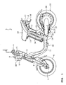
- Fig. 1 is a side view of an electric two-wheeler employing an electric motor according to the present invention.
- An electric two-wheeler 1 shown in Fig. 1 has a body comprising a head pipe 2 at an upper front part.
- a steering shaft (not shown) is rotatably inserted through the head pipe 2, and has an upper end to which handlebars 3 are attached.
- Grips 4 are fitted over the opposite ends of the handlebars 3.
- the grip 4 on the right side (on the far side in Fig. 1, not shown) constitutes a throttle grip which is rotatable.
- the head pipe 2 has a lower part to which an upper part of a pair of right and left front forks 5 are attached.
- the front forks 5 have lower ends at which a front wheel 6 is rotatably mounted on a front wheel shaft 7.
- a meter 8 is disposed on the center of the handlebars 3 and a head lamp 9 is located under the meter 8. Flasher lamps 10 (only one of them is shown in Fig. 1) are provided on both sides of the head lamp 9.
- a pair of right and left body frames 11 extend from the head pipe 2 toward the rear of the body.
- a pair of right and left body frames 12 extend obliquely upward from the rear ends of the body frames 11 and are connected to each other behind a seat 13.
- a battery 14 is located between the right and left body frames 12.
- a seat stay (not shown) having an inverted U-shape is connected to the right and left body frames 12 and supported by a pair of right and left stays 16 (only one of them is shown in the drawing).
- the seat 13 is openably and closably mounted on the seat stay.
- a rear fender 16 is attached to the rear ends of the body frames 12.
- a tail lamp 17 is attached on the rear surface of the rear fender 16. Flasher lamps 18 (only one of them is shown in the drawing) are arranged on right and left sides of the tail lamp 17.
- a pair of right and left rear arm brackets 19 are attached by welding to the rear ends of the right and left body frames 11, respectively.
- a rear arm 20 is supported at the front end by the rear arm brackets 19 via a pivot shaft 21 for vertical swinging movement.
- a rear wheel 22 as a driving wheel is rotatably mounted on the rear end of the rear arm 20.
- the rear arm 20 and the rear wheel 22 are suspended from the body frames 12 by a rear cushion 23.
- the right and left body frames 11 have lower parts to which foot steps 24 (only one of them is shown in the drawing) are attached.
- the rear arm 20 has a lower part on which a side stand 25 is pivoted by a shaft 26.
- the side stand 25 is biased toward the closed position by a return spring 27.
- the rear arm 20 has an approximately circular portion at the rear end, in which an axial gap electric motor 28 is housed.
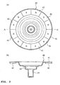
- Fig. 2(a) is a plan view of a stator
- Fig. 2(b) is a sectional view taken on line A-A of Fig. 2(a).
- a stator 31 as a component of the electric motor 28 is housed in a box at the rear end portion of the rear arm, or a case, for fixing.
- the stator 31 is arranged such that a plurality of coils 32 each consisting of a core and a winding are disposed in a circle and molded with resin or the like.
- an encoder board (not shown), so that no coil 32 is disposed in this part.
- Fig. 3(a) is a plan view of a rotor
- Fig. 3(b) is a sectional view taken on line A-A of Fig. 3(a).
- a rotor 40 which is rotated by electromagnetic energy from the stator 31, comprises a yoke 41 and magnetic poles 42 bonded thereto.
- the yoke 41 is formed from a metal plate punched out in a disk-like shape and drawn stepwise concentrically, and formed with a cylindrical shaft portion 43 in its centermost part.
- the shaft portion 43 is a portion by which the yoke 41 is held for rotation.
- To the yoke 41 at the outside circumferential portion are bonded alternately S- and N-magnetic poles 42 of rectangular shape. That is, the yoke 41 is formed, integrally, with a magnetic pole-carrying face, a stepwise drawn portion and the shaft portion 43, so that it can be manufactured at low costs.
- a space 44 for a one-way clutch to be housed is formed by the stepwise drawn portion.
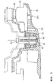
- Fig. 4 are views showing the rotor 40 with the one-way clutch being housed
- Fig. 4(a) is a sectional view taken of line A-A of Fig. 4(b)
- Fig. 4(b) is a sectional view taken on line B-B of Fig. 4(a).
- the one-way clutch 50 allows power transmission from the electric motor 28 to the rear wheel 22 and shuts off power transmission in the opposite direction, for the prevention of overcharging of a battery or for the mitigation of push and walk load.
- the one-way clutch 50 is press-fitted in a space 44 of the yoke 41 having a bearing 45 press-fitted in the shaft portion 43.
- the one-way clutch 50 is arranged such that a plurality of columnar rollers 53 are held between an outer race 51 and an inner race 52 each of a cylindrical shape. These rollers are held separate from each other by a roller holder 54.
- the roller holder 54 has a shape in which portions in the upper part of a cylinder corresponding to the rollers 53 are cut out.
- the outer race 51 is press-fitted in the yoke 41 for fixing.
- the inner race 52 rotates the rear wheel 22 through a planetary gear speed changer (not shown).
- grooves 55 In the inside circumferential surface of the outer race 51 at positions corresponding to the rollers are formed grooves 55 each having different depths at the left and right sides.
- the arrow Y shows the direction of rotation of the yoke 41 when the rear wheel 22 is driven.
- a pin 57 contains a coil spring, having one end connected to the outer race 51 and the other end to the roller holder 54, and biases the roller holder 54 in the direction of Y, so that the rollers 53 are biased toward the shallower sides of the grooves 55.
- the outer race 51 is rotated in the same direction and biases the roller holder 54 in the direction of Y, and the rollers are biased further toward the shallower sides of the grooves 55. Therefore, the rollers 53 are held between the outer race 51 and the inner race 52 and transmit drive force from the outer race 51 to the inner race 52. Thus, the rear wheel is driven.
- a one-way clutch 50 can be disposed using the space, providing a compact structure. That is, a space for the one-way clutch to be housed is formed by the stepwise drawn portion, so that the one-way clutch 50 can be disposed near the rotational axis and thus the moment of inertia becomes lower, enabling the rear wheel to rotate at low torque. Further, the rear wheel 22 becomes compacter, so that a slimmer rear wheel can be materialized with higher design quality. The width of the rear wheel 22 can be decreased, enabling a larger banking.
- a female thread 46 into which a bolt can be fitted.
- Fig. 5 is a view showing a method of removing the rotor 40.
- the rotor 40 is attracted by the stator 31 with its shaft portion 43 inserted in bearings 61, 62 provided in a box at the rear end portion of the rear arm 20, or a case 201.
- a bolt 63 is inserted inside the shaft portion 43 and fitted into the female thread 46 for driving. Then, the forward end of the bolt 63 protrudes relatively from the top of the shaft portion 43.
- the forward end of the bolt 63 comes in abutment against the inner side of the case 201, so that the drive force of the bolt 63 separates the yoke 41 from the stator 31 little by little against the magnetic force of the magnetic poles 42 through reaction from the case 201. Therefore, the rotor can be removed easily from the stator 31 attached to the case 201, as shown in double dot and dash lines.
- a thick portion 64 At a position in the inner side of the case 201 at which the forward end of the bolt 63 is in abutment against the case 201, is formed a thick portion 64, thereby preventing damage to the case 201, or the like.
- a female thread formed in the rotor is required to be provided only in a face perpendicular to the rotational axis, it may be provided at the top of the shaft portion, as in the foregoing rotor 40, or a plurality of female threads may be formed around the rotational axis at regular intervals. This arrangement also allows easy removal of the rotor, improving maintainability.
- Fig. 6 is a view showing a method of removing the rotor 40A having a plurality of female threads formed around the rotational axis at regular intervals.
- a yoke 41A of the rotor 40A has a plurality of female threads 46A (only one is shown in Fig. 6) formed around the rotational axis 22a of the rear wheel 22 at regular intervals.
- female threads 46A into the female threads 46A are fitted corresponding bolts 63 from the opposite side of the stator, which are driven uniformly. Then, the forward ends of the bolts 63 protrude from the yoke 41A and come in abutment against the stator 31, so that the drive force of the bolts 63 separates the yoke 41A from the stator 31 little by little against the magnetic force of the magnetic poles 42 through reaction.
- the rotor can be removed easily from the stator 31 attached to the case 201, as shown in double dot and dash lines.
- the female threads 46A are provided at regular intervals around the rotational axis 22a, so that posture of the rotor 40A is stabilized.
- Fig. 7(a) is a view showing the shape of the rotor 40A in detail
- Fig. 7(b) is an enlarged view of the portion A of Fig. 7(a).
- a yoke 41 of the rotor 40 is formed with a flat face 47 perpendicular to the rotational axis, when magnetic poles 42 are bonded to the yoke 41, an accurate gap control (so called positioning) can be achieved by applying a certain pressure to the magnetic poles with a jig or the like using the flat face 47 as reference, or by controlling the distance from the flat face 47.
- a rotor comprising in combination a face carrying the magnetic poles 42 and a shaft portion 43 will produce the same effect and function if it is formed with a face perpendicular to the rotational axis.
- the rotor 40A since the face perpendicular to the rotational axis is provided in the rotor 40A, the rotor 40A will produce the same effect and function.
- this embodiment can be applied not only to electric motors but also to rotary electric machines including generators.
- the rotary electric machine of this embodiment has a fixed stator, and a rotor rotated by electromagnetic energy from the stator, characterized in that the rotor has in its radially outer region a magnetic pole-carrying face, a stepwise drawn portion concentrical with the face, and a cylindrical shaft portion, on the rotational axis of the rotor, formed in its radially inner region, the shaft portion or the stepwise drawn portion being formed with a face perpendicular to the rotational axis. Therefore, an accurate gap control can be achieved by applying a certain pressure to the magnetic poles with a jig or the like using the flat face as reference, or by controlling the distance from the flat face. As a result, a rotary electric machine with high productivity / maintainability can be provided.
- a space for a one-way clutch to be housed can be formed by the stepwise drawn portion, if the one-way clutch is housed in this space, compacter and thinner design can be materialized.
- the magnetic pole-carrying face, the stepwise drawn portion and the shaft portion are formed integral with each other, handling becomes easier, providing a high productivity.
- the rotor can be removed in a balanced relation.
Landscapes
- Engineering & Computer Science (AREA)
- Power Engineering (AREA)
- Manufacturing & Machinery (AREA)
- Connection Of Motors, Electrical Generators, Mechanical Devices, And The Like (AREA)
- Iron Core Of Rotating Electric Machines (AREA)
- Manufacture Of Motors, Generators (AREA)
- Power Steering Mechanism (AREA)
- Permanent Magnet Type Synchronous Machine (AREA)
- Steering Control In Accordance With Driving Conditions (AREA)
- Arrangement Or Mounting Of Propulsion Units For Vehicles (AREA)
- Reciprocating, Oscillating Or Vibrating Motors (AREA)
Abstract
Description
Claims (6)
- A rotary electric machine having a fixed stator, and a rotor rotated by electromagnetic energy from the stator,
wherein the rotor has in its radially outer region a magnetic pole-carrying face, a stepwise drawn portion concentrical with the face, and a cylindrical shaft portion, on the rotational axis of the rotor, formed in its radially inner region, the shaft portion or the stepwise drawn portion being formed with a face perpendicular to the rotational axis. - The rotary electric machine as set forth in claim 1, wherein a space for a one-way clutch to be housed is formed by the stepwise drawn portion.
- The rotary electric machine as set forth in claim 1 or 2, wherein the magnetic pole-carrying face, the stepwise drawn portion and the shaft portion are formed integral with each other.
- The rotary electric machine as set forth in any of claims 1-3, wherein a female thread is formed in the perpendicular face.
- The rotary electric machine as set forth in claim 4, wherein the female thread is formed on the rotational axis.
- The rotary electric machine as set forth in claim 4, wherein the female thread is formed in a plurality around the rotational axis at regular intervals.
Applications Claiming Priority (3)
| Application Number | Priority Date | Filing Date | Title |
|---|---|---|---|
| JP2002233991 | 2002-08-09 | ||
| JP2002233991 | 2002-08-09 | ||
| PCT/JP2003/010179 WO2004015842A1 (en) | 2002-08-09 | 2003-08-08 | Rotating electrical apparatus |
Publications (3)
| Publication Number | Publication Date |
|---|---|
| EP1553679A1 true EP1553679A1 (en) | 2005-07-13 |
| EP1553679A4 EP1553679A4 (en) | 2006-05-31 |
| EP1553679B1 EP1553679B1 (en) | 2010-12-01 |
Family
ID=31711880
Family Applications (1)
| Application Number | Title | Priority Date | Filing Date |
|---|---|---|---|
| EP03784636A Expired - Lifetime EP1553679B1 (en) | 2002-08-09 | 2003-08-08 | Rotating electrical apparatus |
Country Status (8)
| Country | Link |
|---|---|
| US (1) | US7268462B2 (en) |
| EP (1) | EP1553679B1 (en) |
| JP (1) | JP4050747B2 (en) |
| CN (1) | CN1328838C (en) |
| AT (1) | ATE490584T1 (en) |
| AU (1) | AU2003254912A1 (en) |
| DE (1) | DE60335198D1 (en) |
| WO (1) | WO2004015842A1 (en) |
Families Citing this family (5)
| Publication number | Priority date | Publication date | Assignee | Title |
|---|---|---|---|---|
| TWI283103B (en) * | 2004-02-06 | 2007-06-21 | Yamaha Motor Co Ltd | Rotating electric machine and electrically driven vehicle |
| JP4969873B2 (en) * | 2005-08-05 | 2012-07-04 | ヤマハ発動機株式会社 | Saddle-type vehicle equipped with a rotating electrical machine, and method of mounting the rotating electrical machine |
| FR2890497B1 (en) * | 2005-09-02 | 2007-10-26 | Optelec Sa | ROTOR ENGINE MADE OF A METAL POWDER |
| JP2008193841A (en) * | 2007-02-06 | 2008-08-21 | Yamaha Motor Co Ltd | Axial gap type engine with rotating electric machine |
| EP2061137A1 (en) * | 2007-11-19 | 2009-05-20 | Siemens Aktiengesellschaft | Method for mechanically connecting a disk motor |
Family Cites Families (16)
| Publication number | Priority date | Publication date | Assignee | Title |
|---|---|---|---|---|
| CA1004275A (en) * | 1974-04-04 | 1977-01-25 | Canadian General Electric Company Limited | Permanent magnet synchronous dynamoelectric machine |
| FR2675322A1 (en) * | 1991-04-11 | 1992-10-16 | Ebauchesfabrik Eta Ag | ELECTROMAGNETIC MICROMOTOR WITH AXIAL FLUX. |
| JPH06189488A (en) * | 1992-12-16 | 1994-07-08 | Toshiba Corp | Bracket for rotating electric machine |
| JP2862053B2 (en) * | 1993-04-02 | 1999-02-24 | 三菱電機株式会社 | Motor with drive control device |
| US5497040A (en) * | 1993-11-30 | 1996-03-05 | Sanyo Electric Co., Ltd. | Outer rotor type brusless DC motor |
| JP3015644B2 (en) | 1993-11-30 | 2000-03-06 | 三洋電機株式会社 | Outer rotor type brushless DC motor |
| JPH09215259A (en) * | 1996-01-30 | 1997-08-15 | Asmo Co Ltd | Bearing device |
| JP3739522B2 (en) * | 1997-03-31 | 2006-01-25 | 株式会社ミツバ | Magnet generator rotor |
| ES2199138T3 (en) * | 1999-02-12 | 2004-02-16 | Helmut Schiller | ELECTRIC MACHINE. |
| JP2000308317A (en) | 1999-04-20 | 2000-11-02 | Mitsuba Corp | Starting generator |
| JP4168435B2 (en) | 1999-08-02 | 2008-10-22 | 株式会社デンソー | Generator |
| JP2001112225A (en) * | 1999-10-06 | 2001-04-20 | Denso Corp | Magnet generator |
| JP2001136694A (en) * | 1999-11-08 | 2001-05-18 | Moriyama Manufacturing Co Ltd | Rotor of magnet generator for internal combustion engine |
| JP2001248661A (en) | 2000-03-06 | 2001-09-14 | Unisia Jecs Corp | Electromagnetic / hydraulic clutch |
| JP2003134610A (en) | 2001-10-19 | 2003-05-09 | Yamaha Motor Co Ltd | Motorcycle drive control method |
| JP3982607B2 (en) | 2001-10-19 | 2007-09-26 | ヤマハ発動機株式会社 | Power transmission device for electric motorcycles |
-
2003
- 2003-08-08 WO PCT/JP2003/010179 patent/WO2004015842A1/en not_active Ceased
- 2003-08-08 CN CNB038046482A patent/CN1328838C/en not_active Expired - Fee Related
- 2003-08-08 DE DE60335198T patent/DE60335198D1/en not_active Expired - Lifetime
- 2003-08-08 AT AT03784636T patent/ATE490584T1/en not_active IP Right Cessation
- 2003-08-08 US US10/506,302 patent/US7268462B2/en not_active Expired - Fee Related
- 2003-08-08 EP EP03784636A patent/EP1553679B1/en not_active Expired - Lifetime
- 2003-08-08 JP JP2004527389A patent/JP4050747B2/en not_active Expired - Fee Related
- 2003-08-08 AU AU2003254912A patent/AU2003254912A1/en not_active Abandoned
Also Published As
| Publication number | Publication date |
|---|---|
| CN1647343A (en) | 2005-07-27 |
| JP4050747B2 (en) | 2008-02-20 |
| EP1553679A4 (en) | 2006-05-31 |
| CN1328838C (en) | 2007-07-25 |
| WO2004015842A1 (en) | 2004-02-19 |
| US7268462B2 (en) | 2007-09-11 |
| JPWO2004015842A1 (en) | 2005-12-02 |
| DE60335198D1 (en) | 2011-01-13 |
| ATE490584T1 (en) | 2010-12-15 |
| AU2003254912A1 (en) | 2004-02-25 |
| US20050104471A1 (en) | 2005-05-19 |
| EP1553679B1 (en) | 2010-12-01 |
Similar Documents
| Publication | Publication Date | Title |
|---|---|---|
| US7249643B2 (en) | Hub motor | |
| US8795120B2 (en) | Drive unit for electric bicycle | |
| US7462968B2 (en) | Electric wheel | |
| US8104557B2 (en) | Linear drive travel system and automobile | |
| EP2711286B1 (en) | Drive structure for electric bicycle | |
| EP1955939A2 (en) | Engine with attached axial gap type rotating electric machine | |
| CN100583604C (en) | Rotating electric machine and electric vehicle | |
| TW200914754A (en) | Electric traction drives | |
| WO2011113161A1 (en) | Bicycle with electrical drive system | |
| JP2685315B2 (en) | Electric car | |
| JP3569148B2 (en) | Rotating electric machine and electric vehicle using the same | |
| US7268462B2 (en) | Rotating electrical apparatus | |
| JP2008189029A (en) | Jig for in-wheel motor unit | |
| JP2011235679A (en) | Power-assisted bicycle | |
| JP3835201B2 (en) | Electric assist bicycle motor | |
| CN220139303U (en) | Magnetic force reducing mechanism and hub motor | |
| KR101224443B1 (en) | Drive system for bicycle having decelerating funcing of two drive | |
| EP1388923B1 (en) | Rotating electric machine with adjustable airgap | |
| JP2003095179A (en) | Electrically assisted bicycle | |
| CN223729577U (en) | Hub driving structure | |
| JP6474260B2 (en) | Electric drive device and electric motorcycle | |
| CN219045963U (en) | Control moment gyro and self-balancing vehicle | |
| CN212679962U (en) | Modularization flywheel damping structure and exercise bicycle | |
| KR20070014018A (en) | Electric motor with integral power transmission shaft | |
| KR102010770B1 (en) | Drive system for electric bicycle |
Legal Events
| Date | Code | Title | Description |
|---|---|---|---|
| PUAI | Public reference made under article 153(3) epc to a published international application that has entered the european phase |
Free format text: ORIGINAL CODE: 0009012 |
|
| 17P | Request for examination filed |
Effective date: 20050131 |
|
| AK | Designated contracting states |
Kind code of ref document: A1 Designated state(s): AT BE BG CH CY CZ DE DK EE ES FI FR GB GR HU IE IT LI LU MC NL PT RO SE SI SK TR |
|
| AX | Request for extension of the european patent |
Extension state: AL LT LV MK |
|
| DAX | Request for extension of the european patent (deleted) | ||
| A4 | Supplementary search report drawn up and despatched |
Effective date: 20060420 |
|
| 17Q | First examination report despatched |
Effective date: 20070122 |
|
| GRAP | Despatch of communication of intention to grant a patent |
Free format text: ORIGINAL CODE: EPIDOSNIGR1 |
|
| GRAS | Grant fee paid |
Free format text: ORIGINAL CODE: EPIDOSNIGR3 |
|
| GRAA | (expected) grant |
Free format text: ORIGINAL CODE: 0009210 |
|
| AK | Designated contracting states |
Kind code of ref document: B1 Designated state(s): AT BE BG CH CY CZ DE DK EE ES FI FR GB GR HU IE IT LI LU MC NL PT RO SE SI SK TR |
|
| REG | Reference to a national code |
Ref country code: GB Ref legal event code: FG4D |
|
| REG | Reference to a national code |
Ref country code: CH Ref legal event code: NV Representative=s name: PATENTANWALTSBUERO JEAN HUNZIKER AG Ref country code: CH Ref legal event code: EP |
|
| REG | Reference to a national code |
Ref country code: IE Ref legal event code: FG4D |
|
| REF | Corresponds to: |
Ref document number: 60335198 Country of ref document: DE Date of ref document: 20110113 Kind code of ref document: P |
|
| REG | Reference to a national code |
Ref country code: NL Ref legal event code: T3 |
|
| PG25 | Lapsed in a contracting state [announced via postgrant information from national office to epo] |
Ref country code: SE Free format text: LAPSE BECAUSE OF FAILURE TO SUBMIT A TRANSLATION OF THE DESCRIPTION OR TO PAY THE FEE WITHIN THE PRESCRIBED TIME-LIMIT Effective date: 20101201 Ref country code: SI Free format text: LAPSE BECAUSE OF FAILURE TO SUBMIT A TRANSLATION OF THE DESCRIPTION OR TO PAY THE FEE WITHIN THE PRESCRIBED TIME-LIMIT Effective date: 20101201 Ref country code: AT Free format text: LAPSE BECAUSE OF FAILURE TO SUBMIT A TRANSLATION OF THE DESCRIPTION OR TO PAY THE FEE WITHIN THE PRESCRIBED TIME-LIMIT Effective date: 20101201 Ref country code: BG Free format text: LAPSE BECAUSE OF FAILURE TO SUBMIT A TRANSLATION OF THE DESCRIPTION OR TO PAY THE FEE WITHIN THE PRESCRIBED TIME-LIMIT Effective date: 20110301 Ref country code: FI Free format text: LAPSE BECAUSE OF FAILURE TO SUBMIT A TRANSLATION OF THE DESCRIPTION OR TO PAY THE FEE WITHIN THE PRESCRIBED TIME-LIMIT Effective date: 20101201 Ref country code: CY Free format text: LAPSE BECAUSE OF FAILURE TO SUBMIT A TRANSLATION OF THE DESCRIPTION OR TO PAY THE FEE WITHIN THE PRESCRIBED TIME-LIMIT Effective date: 20101201 |
|
| PG25 | Lapsed in a contracting state [announced via postgrant information from national office to epo] |
Ref country code: GR Free format text: LAPSE BECAUSE OF FAILURE TO SUBMIT A TRANSLATION OF THE DESCRIPTION OR TO PAY THE FEE WITHIN THE PRESCRIBED TIME-LIMIT Effective date: 20110302 |
|
| PG25 | Lapsed in a contracting state [announced via postgrant information from national office to epo] |
Ref country code: EE Free format text: LAPSE BECAUSE OF FAILURE TO SUBMIT A TRANSLATION OF THE DESCRIPTION OR TO PAY THE FEE WITHIN THE PRESCRIBED TIME-LIMIT Effective date: 20101201 Ref country code: CZ Free format text: LAPSE BECAUSE OF FAILURE TO SUBMIT A TRANSLATION OF THE DESCRIPTION OR TO PAY THE FEE WITHIN THE PRESCRIBED TIME-LIMIT Effective date: 20101201 Ref country code: PT Free format text: LAPSE BECAUSE OF FAILURE TO SUBMIT A TRANSLATION OF THE DESCRIPTION OR TO PAY THE FEE WITHIN THE PRESCRIBED TIME-LIMIT Effective date: 20110401 Ref country code: BE Free format text: LAPSE BECAUSE OF FAILURE TO SUBMIT A TRANSLATION OF THE DESCRIPTION OR TO PAY THE FEE WITHIN THE PRESCRIBED TIME-LIMIT Effective date: 20101201 Ref country code: ES Free format text: LAPSE BECAUSE OF FAILURE TO SUBMIT A TRANSLATION OF THE DESCRIPTION OR TO PAY THE FEE WITHIN THE PRESCRIBED TIME-LIMIT Effective date: 20110312 |
|
| PG25 | Lapsed in a contracting state [announced via postgrant information from national office to epo] |
Ref country code: RO Free format text: LAPSE BECAUSE OF FAILURE TO SUBMIT A TRANSLATION OF THE DESCRIPTION OR TO PAY THE FEE WITHIN THE PRESCRIBED TIME-LIMIT Effective date: 20101201 Ref country code: SK Free format text: LAPSE BECAUSE OF FAILURE TO SUBMIT A TRANSLATION OF THE DESCRIPTION OR TO PAY THE FEE WITHIN THE PRESCRIBED TIME-LIMIT Effective date: 20101201 |
|
| PLBE | No opposition filed within time limit |
Free format text: ORIGINAL CODE: 0009261 |
|
| STAA | Information on the status of an ep patent application or granted ep patent |
Free format text: STATUS: NO OPPOSITION FILED WITHIN TIME LIMIT |
|
| PG25 | Lapsed in a contracting state [announced via postgrant information from national office to epo] |
Ref country code: DK Free format text: LAPSE BECAUSE OF FAILURE TO SUBMIT A TRANSLATION OF THE DESCRIPTION OR TO PAY THE FEE WITHIN THE PRESCRIBED TIME-LIMIT Effective date: 20101201 |
|
| 26N | No opposition filed |
Effective date: 20110902 |
|
| REG | Reference to a national code |
Ref country code: DE Ref legal event code: R097 Ref document number: 60335198 Country of ref document: DE Effective date: 20110902 |
|
| PG25 | Lapsed in a contracting state [announced via postgrant information from national office to epo] |
Ref country code: MC Free format text: LAPSE BECAUSE OF NON-PAYMENT OF DUE FEES Effective date: 20110831 |
|
| GBPC | Gb: european patent ceased through non-payment of renewal fee |
Effective date: 20110808 |
|
| REG | Reference to a national code |
Ref country code: IE Ref legal event code: MM4A |
|
| PG25 | Lapsed in a contracting state [announced via postgrant information from national office to epo] |
Ref country code: IE Free format text: LAPSE BECAUSE OF NON-PAYMENT OF DUE FEES Effective date: 20110808 |
|
| PG25 | Lapsed in a contracting state [announced via postgrant information from national office to epo] |
Ref country code: GB Free format text: LAPSE BECAUSE OF NON-PAYMENT OF DUE FEES Effective date: 20110808 |
|
| PG25 | Lapsed in a contracting state [announced via postgrant information from national office to epo] |
Ref country code: LU Free format text: LAPSE BECAUSE OF NON-PAYMENT OF DUE FEES Effective date: 20110808 |
|
| PG25 | Lapsed in a contracting state [announced via postgrant information from national office to epo] |
Ref country code: TR Free format text: LAPSE BECAUSE OF FAILURE TO SUBMIT A TRANSLATION OF THE DESCRIPTION OR TO PAY THE FEE WITHIN THE PRESCRIBED TIME-LIMIT Effective date: 20101201 |
|
| PG25 | Lapsed in a contracting state [announced via postgrant information from national office to epo] |
Ref country code: HU Free format text: LAPSE BECAUSE OF FAILURE TO SUBMIT A TRANSLATION OF THE DESCRIPTION OR TO PAY THE FEE WITHIN THE PRESCRIBED TIME-LIMIT Effective date: 20101201 |
|
| REG | Reference to a national code |
Ref country code: FR Ref legal event code: PLFP Year of fee payment: 13 |
|
| PGFP | Annual fee paid to national office [announced via postgrant information from national office to epo] |
Ref country code: FR Payment date: 20150626 Year of fee payment: 13 |
|
| PGFP | Annual fee paid to national office [announced via postgrant information from national office to epo] |
Ref country code: DE Payment date: 20150821 Year of fee payment: 13 Ref country code: CH Payment date: 20150819 Year of fee payment: 13 |
|
| PGFP | Annual fee paid to national office [announced via postgrant information from national office to epo] |
Ref country code: NL Payment date: 20150830 Year of fee payment: 13 |
|
| PGFP | Annual fee paid to national office [announced via postgrant information from national office to epo] |
Ref country code: IT Payment date: 20150824 Year of fee payment: 13 |
|
| REG | Reference to a national code |
Ref country code: DE Ref legal event code: R119 Ref document number: 60335198 Country of ref document: DE |
|
| REG | Reference to a national code |
Ref country code: CH Ref legal event code: PL |
|
| REG | Reference to a national code |
Ref country code: NL Ref legal event code: MM Effective date: 20160901 |
|
| PG25 | Lapsed in a contracting state [announced via postgrant information from national office to epo] |
Ref country code: CH Free format text: LAPSE BECAUSE OF NON-PAYMENT OF DUE FEES Effective date: 20160831 Ref country code: LI Free format text: LAPSE BECAUSE OF NON-PAYMENT OF DUE FEES Effective date: 20160831 |
|
| REG | Reference to a national code |
Ref country code: FR Ref legal event code: ST Effective date: 20170428 |
|
| PG25 | Lapsed in a contracting state [announced via postgrant information from national office to epo] |
Ref country code: NL Free format text: LAPSE BECAUSE OF NON-PAYMENT OF DUE FEES Effective date: 20160901 |
|
| PG25 | Lapsed in a contracting state [announced via postgrant information from national office to epo] |
Ref country code: DE Free format text: LAPSE BECAUSE OF NON-PAYMENT OF DUE FEES Effective date: 20170301 Ref country code: FR Free format text: LAPSE BECAUSE OF NON-PAYMENT OF DUE FEES Effective date: 20160831 |
|
| PG25 | Lapsed in a contracting state [announced via postgrant information from national office to epo] |
Ref country code: IT Free format text: LAPSE BECAUSE OF NON-PAYMENT OF DUE FEES Effective date: 20160808 |