EP1553579A1 - Method of delivering substrate to film forming device for disk-like substrate, mechanism for delivering substrate used for the method, substrate holder, and method of manufacturing disk-like recording medium using the method - Google Patents
Method of delivering substrate to film forming device for disk-like substrate, mechanism for delivering substrate used for the method, substrate holder, and method of manufacturing disk-like recording medium using the method Download PDFInfo
- Publication number
- EP1553579A1 EP1553579A1 EP03733431A EP03733431A EP1553579A1 EP 1553579 A1 EP1553579 A1 EP 1553579A1 EP 03733431 A EP03733431 A EP 03733431A EP 03733431 A EP03733431 A EP 03733431A EP 1553579 A1 EP1553579 A1 EP 1553579A1
- Authority
- EP
- European Patent Office
- Prior art keywords
- mask
- substrate
- magnet
- holding
- substrate holder
- Prior art date
- Legal status (The legal status is an assumption and is not a legal conclusion. Google has not performed a legal analysis and makes no representation as to the accuracy of the status listed.)
- Withdrawn
Links
- 239000000758 substrate Substances 0.000 title claims abstract description 308
- 238000000034 method Methods 0.000 title claims abstract description 36
- 230000007246 mechanism Effects 0.000 title claims abstract description 26
- 238000004519 manufacturing process Methods 0.000 title claims description 15
- 230000002093 peripheral effect Effects 0.000 claims abstract description 20
- 239000010408 film Substances 0.000 claims description 35
- 230000015572 biosynthetic process Effects 0.000 claims description 30
- 239000010409 thin film Substances 0.000 claims description 30
- 230000000994 depressogenic effect Effects 0.000 claims description 3
- 238000004544 sputter deposition Methods 0.000 abstract description 18
- 230000008569 process Effects 0.000 description 13
- 238000010276 construction Methods 0.000 description 11
- 239000011347 resin Substances 0.000 description 7
- 229920005989 resin Polymers 0.000 description 7
- 238000009826 distribution Methods 0.000 description 5
- 230000003287 optical effect Effects 0.000 description 5
- 238000004528 spin coating Methods 0.000 description 5
- 230000002159 abnormal effect Effects 0.000 description 4
- 230000009471 action Effects 0.000 description 4
- 230000007423 decrease Effects 0.000 description 3
- 230000000694 effects Effects 0.000 description 3
- 150000002500 ions Chemical class 0.000 description 2
- 238000003754 machining Methods 0.000 description 2
- 239000000463 material Substances 0.000 description 2
- 239000002184 metal Substances 0.000 description 2
- 238000003825 pressing Methods 0.000 description 2
- 230000009467 reduction Effects 0.000 description 2
- 238000009825 accumulation Methods 0.000 description 1
- 239000000853 adhesive Substances 0.000 description 1
- 230000001070 adhesive effect Effects 0.000 description 1
- 230000002411 adverse Effects 0.000 description 1
- 238000013459 approach Methods 0.000 description 1
- 230000008859 change Effects 0.000 description 1
- 229910052729 chemical element Inorganic materials 0.000 description 1
- 239000000470 constituent Substances 0.000 description 1
- 230000005684 electric field Effects 0.000 description 1
- 230000020169 heat generation Effects 0.000 description 1
- 238000010030 laminating Methods 0.000 description 1
- 239000000696 magnetic material Substances 0.000 description 1
- 239000002245 particle Substances 0.000 description 1
- 229920000515 polycarbonate Polymers 0.000 description 1
- 239000004417 polycarbonate Substances 0.000 description 1
- 230000005855 radiation Effects 0.000 description 1
- 230000000630 rising effect Effects 0.000 description 1
- 238000007740 vapor deposition Methods 0.000 description 1
Images




Classifications
-
- G—PHYSICS
- G11—INFORMATION STORAGE
- G11B—INFORMATION STORAGE BASED ON RELATIVE MOVEMENT BETWEEN RECORD CARRIER AND TRANSDUCER
- G11B7/00—Recording or reproducing by optical means, e.g. recording using a thermal beam of optical radiation by modifying optical properties or the physical structure, reproducing using an optical beam at lower power by sensing optical properties; Record carriers therefor
- G11B7/24—Record carriers characterised by shape, structure or physical properties, or by the selection of the material
- G11B7/26—Apparatus or processes specially adapted for the manufacture of record carriers
- G11B7/266—Sputtering or spin-coating layers
-
- C—CHEMISTRY; METALLURGY
- C23—COATING METALLIC MATERIAL; COATING MATERIAL WITH METALLIC MATERIAL; CHEMICAL SURFACE TREATMENT; DIFFUSION TREATMENT OF METALLIC MATERIAL; COATING BY VACUUM EVAPORATION, BY SPUTTERING, BY ION IMPLANTATION OR BY CHEMICAL VAPOUR DEPOSITION, IN GENERAL; INHIBITING CORROSION OF METALLIC MATERIAL OR INCRUSTATION IN GENERAL
- C23C—COATING METALLIC MATERIAL; COATING MATERIAL WITH METALLIC MATERIAL; SURFACE TREATMENT OF METALLIC MATERIAL BY DIFFUSION INTO THE SURFACE, BY CHEMICAL CONVERSION OR SUBSTITUTION; COATING BY VACUUM EVAPORATION, BY SPUTTERING, BY ION IMPLANTATION OR BY CHEMICAL VAPOUR DEPOSITION, IN GENERAL
- C23C14/00—Coating by vacuum evaporation, by sputtering or by ion implantation of the coating forming material
- C23C14/04—Coating on selected surface areas, e.g. using masks
- C23C14/042—Coating on selected surface areas, e.g. using masks using masks
-
- C—CHEMISTRY; METALLURGY
- C23—COATING METALLIC MATERIAL; COATING MATERIAL WITH METALLIC MATERIAL; CHEMICAL SURFACE TREATMENT; DIFFUSION TREATMENT OF METALLIC MATERIAL; COATING BY VACUUM EVAPORATION, BY SPUTTERING, BY ION IMPLANTATION OR BY CHEMICAL VAPOUR DEPOSITION, IN GENERAL; INHIBITING CORROSION OF METALLIC MATERIAL OR INCRUSTATION IN GENERAL
- C23C—COATING METALLIC MATERIAL; COATING MATERIAL WITH METALLIC MATERIAL; SURFACE TREATMENT OF METALLIC MATERIAL BY DIFFUSION INTO THE SURFACE, BY CHEMICAL CONVERSION OR SUBSTITUTION; COATING BY VACUUM EVAPORATION, BY SPUTTERING, BY ION IMPLANTATION OR BY CHEMICAL VAPOUR DEPOSITION, IN GENERAL
- C23C14/00—Coating by vacuum evaporation, by sputtering or by ion implantation of the coating forming material
- C23C14/22—Coating by vacuum evaporation, by sputtering or by ion implantation of the coating forming material characterised by the process of coating
- C23C14/50—Substrate holders
-
- G—PHYSICS
- G11—INFORMATION STORAGE
- G11B—INFORMATION STORAGE BASED ON RELATIVE MOVEMENT BETWEEN RECORD CARRIER AND TRANSDUCER
- G11B7/00—Recording or reproducing by optical means, e.g. recording using a thermal beam of optical radiation by modifying optical properties or the physical structure, reproducing using an optical beam at lower power by sensing optical properties; Record carriers therefor
- G11B7/24—Record carriers characterised by shape, structure or physical properties, or by the selection of the material
- G11B7/26—Apparatus or processes specially adapted for the manufacture of record carriers
- G11B7/265—Apparatus for the mass production of optical record carriers, e.g. complete production stations, transport systems
Definitions
- the present invention relates to a thin film forming device for forming a thin film on a disk-shaped substrate. More specifically, the present invention relates to a method of delivering to the device a disk-shaped substrate used in the device, and to a mechanism used in the method. Further, the present invention also relates to a so-called substrate holder used with the mechanism, and a disk-shaped recording medium manufacturing method for manufacturing a disk-shaped recording medium such as a so-called optical disk by using the mechanism.
- Examples of recording media manufactured by forming a thin film of various kinds on a disk-shaped substrate include: optical disks including CD disks such as a CD, a CD-R, or a CD-RW, and DVD disks such as a DVD-ROM or a DVD-R; optical magnetic disks such as an MO or an MD; and various other types of disks.
- Those disks are manufactured by laminating a thin film on a substrate made of a polycarbonate material, for example, by various methods such as sputtering or spin coating.
- a through hole is already formed in the central portion thereof to facilitate disk handling when those disks are actually used as recording media.
- disk handling operations are usually performed using this center hole, including transporting of the substrate to and from a thin film forming device or the like, positioning of the substrate in the thin film forming device, and the like.
- this center hole may, for example, cause a reduction in the thin film thickness or thin film distribution on the substrate.
- a commonly used solution to this problem is to cover the center hole with a cap or the like when performing film formation, thereby minimizing the influence that the center hole may exert on the film formation process.
- a thin film made of an ultraviolet curing resin which is one of the films constituting the disk, is formed by spin coating.
- a substrate is mounted on a rotatable table such that the center of the substrate coincides with the rotation center of the table. Accordingly, the substrate is positioned and fixed with respect to the table through such operations as using a rotation shaft that passes through the center hole, or placing a cap, which is fixed concentrically with respect to the rotation center of the table, over the center hole of the disk.
- resin is successively supplied dropwise to the rotating disk from the vicinity of the center hole or an end portion of the cap toward the outer periphery of the disk.
- the resin thus supplied dropwise is dispersed due to the centrifugal force generated by the disk rotation, forming a resin thin film on the substrate surface.
- the resin thin film thus obtained then undergoes steps such as irradiation of ultraviolet rays, thus providing a stable film structure.
- the resin must be dropped at a position off the rotation center, leading to the occurrence of a film thickness distribution.
- red laser light which is currently commonly used for reading of a record, has a relatively long wavelength, hence keeping such a film thickness distribution within the permissible range.
- blue laser light which has a short wavelength, comes to be used in the near future to increase the recording density of optical disks, it becomes necessary to obtain a thin film with more uniform thickness.
- the applicant of the present invention has proposed a manufacturing process using a substrate with no hole provided at the central portion thereof. In this manufacturing process, a through hole is formed at the central portion of the substrate after forming a thin film of various kinds thereon.
- a metal thin film or the like used for a reflection film or the like is formed by sputtering.
- a disk-shaped substrate is fixed and held onto the front side of a target within a vacuum container.
- a given voltage is applied to the target and electric discharge thus takes place between the target and the substrate, generating plasma.
- the constituent chemical elements of the target on the target surface are sputtered with ions in the plasma, and the sputtered particles adhere onto the substrate surface, thus effecting film formation.
- the rear side of the substrate is held in intimate contact with the substrate holder and heat is released through the substrate holder to some extent, so that large accumulation of heat does not take place and it is unlikely that such warping becomes a problem.
- the heat release cannot keep pace with the heat generation, and the central portion of the substrate separates from the substrate holder that is holding the substrate due to the resulting warping, that is, from the holder to which heat is to be transferred. In this case, the amount of heat release decreases, causing the substrate temperature to rise further and thus increasing the deformation of the substrate.
- One way to overcome this problem would be to provide a mechanism for forcibly pressing the central portion of the substrate, where the largest deformation tends to take place, onto the substrate holder.
- This method can be implemented relatively easily when using the conventional substrate having a through hole at its central portion, by using a so-called inner mask that covers the central portion.
- the inventor of the present invention has devised and proposed a novel substrate chucking method for chucking a substrate having no through hole at its central portion inside a sputtering device.
- the inventor of the present invention has also proposed a substrate transporting mechanism or the like capable of performing reliable transfer or the like of not only the substrate but also the outer mask that covers the outer peripheral portion of the substrate.
- a film formation process with a sputtering device by using such a mechanism involves a problem in that the central portion of the substrate may undergo warping, and some solution to this problem will have to be implemented.
- a substrate delivering method according to the present invention has been devised in view of the above-described requirement, and therefore an object of the present invention is to make it possible to reliably maintain the relative positional relation between the outer mask etc and the substrate during transport of a substrate. Further, another object of the present invention is to provide a substrate delivering mechanism for a thin film forming device such as a sputtering device embodying the above delivering method, and a disk-shaped recording medium manufacturing method using this device.
- the substrate be fixed onto the outer mask by in-mask substrate-holding means provided in the outer mask, and that the delivering of the substrate be performed with the substrate and the outer mask being integrated together.
- the magnet provided in the substrate holder be arranged in a substantially central portion of the substrate holder and a vicinity thereof and at a position substantially corresponding to the outer mask.
- a substrate holder for holding, during film formation on a substantially disk-shaped substrate having a projection portion at a center of its back surface, the substrate, an outer mask adapted to cover an outer peripheral surface portion of the substrate, and an inner mask adapted to cover a central surface portion of the substrate, including: a substantially annular substrate receiving surface adapted to receive the back surface of the substrate; a cylindrical recess provided at a center portion of the substrate receiving surface; an inner-mask fixing magnet received in the recess; and an outer-mask receiving surface provided in a periphery of the substrate receiving surface and depressed with respect to the substrate receiving surface.
- the inner-mask fixing magnet have a substantially cylindrical shape with a hole having a diameter large enough to receive the projection portion on the back surface of the substrate. Further, it is preferable that the inner-mask fixing magnet be fixed onto an arbitrary portion of the recess through an elastic member.
- a substrate delivering mechanism which holds a substantially disk-shaped substrate together with an outer mask and an inner mask, the substrate having a projection portion at a central portion of its back surface, the outer mask being adapted to cover an outer peripheral portion of the substrate, the inner mask being adapted to cover a central portion of the substrate, and which transfers the substrate, the inner mask, and the outer mask to a substrate holding mechanism, including: an inner-mask receiving surface for supporting the inner mask; a magnet for inner mask which is arranged underneath the inner-mask receiving surface and capable of moving toward and away from the inner-mask receiving surface; an outer-mask receiving surface for supporting the outer mask; and a magnet for outer mask which is arranged underneath the outer-mask receiving surface and capable of moving toward and away from the outer-mask receiving surface, the substrate delivering mechanism being characterized in that the substrate is held in a predetermined position by fixing and holding the inner mask and the outer mask in predetermined positions by a magnetic force exert
- the inner-mask receiving surface and the outer-mask receiving surface lie on the same plane.
- a disk-shaped recording medium manufacturing method using a substantially disk-shaped substrate including: fixing and holding respective surfaces of an inner mask and an outer mask onto a mask holding surface of a substrate transport arm by a magnetic force, the inner mask being adapted to cover a central surface portion of the substrate, the outer mask being adapted to cover an outer peripheral portion of the substrate, and supporting a predetermined surface portion of the substrate by respective back surfaces of the inner mask and the outer mask; opposing a substrate holder to the mask holding surface of the transport arm on which the inner mask, the outer mask, and the substrate are held; causing a magnetic force to be exerted from the substrate holder onto the inner mask and the outer mask; reducing the magnetic force exerted from the transport arm onto the inner mask and the outer mask; sandwiching the substrate by the inner mask and the outer mask by fixing and holding the respective back surfaces of the inner mask and the outer mask onto the substrate holder by the magnetic force exerted from the substrate holder; transporting the substrate
- the transporting of the substrate holder from the substrate transport arm to the thin film forming device be performed in a state in which the substrate and a mask that covers an outer peripheral end portion of a film formation surface of the substrate are integrated together by in-mask substrate-fixing means provided in the mask.
- the substrate have a projection portion on its back surface, and the substrate holder has a receiving hole which receives the projection portion.
- Fig. 1 is a schematic cross-sectional view showing the substrate holder, which can be held together with the substrate by this delivering mechanism and actually holds the substrate during the film formation process with a sputtering device or the like, the substrate, an outer mask, and an inner mask that are held by the substrate holder.
- Fig. 2 is a schematic cross-sectional view of an atmosphere-side transport arm having the substrate delivering mechanism, which is arranged substantially facing the substrate holder that is holding the substrate and delivers the substrate and the masks between the substrate delivering mechanism and the substrate holder.
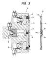
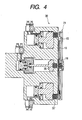
- Figs. 3 through 6 are schematic cross-sectional views each illustrating how delivery of the substrate is effected according to the above-described construction.
- a substrate 10 used in the present invention is formed in a substantially disk-like shape and has a first projection portion 9 formed at the central portion of its film formation surface and a second projection portion 11 formed at the central portion of the rear side of the film formation surface.
- the projection portions each have a substantially columnar shape whose axial center coincides with the center of the substrate.
- the inner-mask fixing magnet 24 has a cylindrical configuration with an opening 24a provided on the substrate back surface side and a bottom portion 24b provided on the side opposite therefrom.
- the magnet 24 is arranged with an end portion of the opening 24a facing the substrate back surface side such that the second projection portion 11 on the substrate back surface is fitted in the opening 24a.
- the magnet 24 has a screw hole (not shown) formed in the bottom surface 24b constituting the other end portion thereof.
- the magnet 24 is fixed onto the bottom surface of the recess 23 of the substrate holder 21 by using this screw hole. It is to be noted that the above-described structure is employed for the purpose of fixing the inner-mask fixing magnet 24 onto the bottom surface of the recess 23 with sufficient strength and precision. Hence, as long as this requirement can be met, it is also possible to simply affix the cylindrical magnet onto the bottom surface of the recess with an adhesive or the like.
- An inner mask 18 has a substantially disk-like configuration whose height from the surface in intimate contact with the substrate 10 surface decreases with increasing proximity to its end portions.
- the inner mask 18 has a receiving recess 19, which receives the first projection portion 9 of the substrate surface, provided at the center of its surface that is in intimate contact with the substrate 10. Fitting the first projection portion 9 into the receiving recess 19 effects the positioning between the substrate 10 and the inner mask.
- the inner mask 18, which is formed of a magnetic material comes into intimate contact with the substrate surface while substantially pressing the substrate 10 against the magnet 24 by means of the magnetic force of the inner-mask fixing magnet 24 arranged on the back surface of the substrate 10. Since the central portion of the substrate is thus urged toward the substrate holder 21 side, warping of the substrate 10 can be suppressed even in situations where the substrate 10 is liable to undergo thermal expansion during the sputtering process.
- annular groove 12 into which the substrate-side end portion of the inner-mask fixing magnet 24 is fitted, in the periphery of the second projection portion 9 on the substrate back surface in order to keep the relative positional relation between the substrate 10 and the inner-mask fixing magnet 24 constant. That is, the height of the inner-mask fixing magnet 24 and the depth of the recess 23 are so adjusted that the substrate-side end portion of the inner-mask fixing magnet 24 can be fitted in the annular groove 12 but does not reach the bottom surface of the recess 23 provided in the substrate holder 21.
- the above-described construction enables a reduction in substrate thickness at the central portion, providing such effects as greater magnetic force exerted on the inner mask by the inner-mask fixing magnet 24 and also reduced deformation force acting on the central portion of the substrate 10 upon thermal deformation. It is not particularly necessary to provide the annular groove 12, however, provided that the warping of the substrate central portion can be reliably suppressed by the inner mask 18 and the inner-mask fixing magnet 24.
- An outer mask 15 has a ring-shaped outer-mask main body 17 whose inner diameter is larger than the outer diameter of the substrate, and an outer mask flange portion 16 projecting toward the inner peripheral side from one end face of the outer-mask main body 17 and adapted to cover the outer peripheral end portion of the substrate 10. Further, provided inside the outer-mask main body 17 is an in-mask ball plunger 27.
- the outer mask flange portion 16 must have a width which provides a sufficient distance between the outer-mask main body 17 supporting it and the substrate 10 to prevent abnormal electric discharge from occurring therebetween during film formation by sputtering. Further, to minimize its influence on the electric field during film formation, the outer mask flange portion 16 is provided with a tapered portion, sloping toward the other end face thereof with increasing proximity to its inner peripheral end portion.
- a minute gap of a predetermined value or less must be provided between the inner peripheral end portion of the outer mask flange portion 16 and the surface of the substrate 10 to prevent the occurrence of abnormal electric discharge and contact therebetween during film formation by sputtering. Therefore, in supporting the outer mask 15 by the outer-mask receiving portion 26, the thickness of the outer-mask main body 17 and the thickness of the outer mask flange portion 16, the method of supporting the outer mask 15, etc must be determined according to the electric discharge conditions to satisfy the above requirement. It is to be noted that the conditions and the like regarding the configuration of the mask flange portion also apply to the outer peripheral end portion of the inner mask 18.
- the in-mask ball plunger 27 serving as in-mask substrate-fixing means urges the substrate 10 toward the outer mask 15 by an in-mask spring 28 such that the center of the substrate 10 coincides with that of the outer mask 15. At the same time, the in-mask ball plunger 27 sandwiches the end portion of the substrate 10 with the outer mask flange portion 16, thus keeping the relative positional relation between the outer mask 15 and the substrate 10 constant at all times.
- the outer mask 15 is held and fixed in intimate contact with the outer-mask receiving portion 26 by the magnetic force generated by an outer-mask fixing magnet (not shown) located in the outer-mask receiving portion 26.
- an outer-mask fixing magnet (not shown) located in the outer-mask receiving portion 26.
- the back surface of the substrate 10 is held in intimate contact with a substantially annular flat surface formed as the substrate receiving portion 22.
- the outer-mask receiving portion 26 includes a region of precise flatness formed in the vicinity of its outer periphery.
- This region serves as ah outer-mask receiving surface 26a which protrudes slightly toward the outer mask 15 side with respect to other portions of the outer-mask receiving portion 26, and the outer-mask receiving surface 26a actually supports the outer mask 15.
- This construction makes it possible to hold the outer mask 15 in position with good precision while reducing the area which requires high-precision machining.
- an atmosphere-side transport arm 30 serving as a substrate delivering mechanism has a substantially flat mask-receiving surface 33, a magnet for inner mask 35 and a magnet for outer mask 37 which are arranged underneath the mask receiving surface and capable of moving relative to the mask receiving surface, and an air cylinder 36 for the outer mask and an air cylinder for inner mask 38 which are capable of moving the magnets 35 and 37, respectively, toward and away from the mask receiving surface 33.
- the upper end surfaces (the side opposite from the substrate holder side) of the inner mask 18 and the outer mask 15 lie on the same plane when those masks are integrated together with the substrate 10. Accordingly, by keeping the mask receiving surface 33 substantially planar, it is possible to hold the substrate and the like in a stable manner.
- the magnet for inner mask 35 is arranged at a position corresponding to the substantially central portion of the mask receiving surface 33. With the magnet for inner mask 35 taken as the center position, the magnet for outer mask 37 is arranged at a position substantially corresponding to the outer-mask main body 17 of the substantially ring-shaped outer mask 15. It is to be noted that various positional arrangements may be adopted for the magnet for outer mask 37, such as providing a pair of magnets 37 at symmetrical positions, providing a plurality of magnets 37 radially, or adopting a substantially annular arrangement, with respect to the magnet for inner mask 35 taken as the center.
- the positional relation between the substrate 10 and the outer mask 15 is determined by the action of the in-mask ball plunger 27, and they are transferred integrally at all times.
- the substrate holder 21 that is not holding the substrate and the like, and the atmosphere-side transport arm 30 holding the outer mask 15 on the mask receiving surface 33 by the action of the magnet 35 are arranged to face each other.
- the vacuum-side transport arm which supports the substrate holder and transfers it into a vacuum device, is omitted from the drawing.
- the atmosphere-side transport arm 30 approaches the substrate holder 21, stopping at a predetermined distance from the substrate holder 21.
- This state is shown in Fig. 4.
- the second projection portion 11 of the substrate is inserted into the central recess of the inner-mask fixing magnet 24 arranged in the substrate holder 21, with the substrate-side end portion of the inner-mask fixing magnet 24 being fitted in the annular recess 12 on the substrate back surface.
- the magnet for inner mask 35 and the magnet for outer mask 37 are separated from the substrate receiving surface 33 substantially simultaneously by the air cylinder for inner mask 36 and the air cylinder for outer mask 38, respectively.
- the magnetic forces exerted on the inner mask 18 and the outer mask 15 by the magnet for inner mask 35 and the magnet for outer mask 37, respectively decrease and the magnetic forces exerted from the substrate holder 21 side keep the respective masks held in position.
- the inner-mask fixing magnet 24 and the outer-mask fixing magnet are arranged at positions substantially corresponding to the magnet for inner mask 35 and the magnet for outer mask 37, respectively, on the atmosphere-side transport arm 30 side. Therefore, the holding positions and attitudes or the like of the inner and outer masks 15 and 18 basically do not change even through those magnets, which are previously held in position by the magnetic forces exerted from the atmosphere-side transport arm 30, are now held in position by the magnetic forces exerted from the substrate holder 21 side.
- the atmosphere-side transport arm 30 retracts, and the substrate holder 21 that is holding the substrate 10 and the mask 15 is transported to the sputtering device by the vacuum side transport arm (not shown), thus executing the film formation process.
- the substrate holder 21 holding the substrate 10 that has undergone the film formation process returns to the position where the substrate holder 21 faces the atmosphere-side transport arm 30.
- delivery of the substrate 10 and the like from the vacuum-side transport arm to the atmosphere-side transport arm 30 is performed through a procedure reverse to the delivery of the substrate 10 described above.
- Fig. 7 is a schematic cross-sectional view of a substrate holder according to a second embodiment of the present invention, and the substrate, the outer mask, and the inner mask that are being held by the holder.
- the substrate holder can be held together with the substrate by the delivering mechanism according to the present invention and actually holds the substrate during film formation with the sputtering device or the like. It is to be noted that the construction of this embodiment except the substrate delivering mechanism is virtually unchanged from that of the first embodiment, and description thereof is thus omitted here.
- the substrate holder of this embodiment is different from that of the first embodiment only in that an elastic member is provided on the bottom surface of the magnet 24.
- the magnet 24 has the screw hole or the like (not shown) on the bottom surface 24b, and the magnet 24 is fixed onto the bottom surface of the recess 23 of the substrate holder 21 by using this screw hole or the like. Therefore, cases may occur in which, for example, due to the mounting precision of the magnet 24 and the thickness of the substrate 10, an end portion of the magnet 24 cannot come into contact with the substrate 10 back surface or the bottom surface of the annular groove 12, making it impossible for the magnet 24 to exert a sufficient magnetic force onto the inner mask 18.
- the magnet 24 is fixed onto the bottom surface of the recess 23 with the elastic member 29 being interposed therebetween.
- the elastic member 29 enables slight movement of the magnet 24 in the direction of the substrate so that the end portion of the magnet 24 contacts the substrate 10 back surface or the like at all times, making it possible to exert onto the inner mask 18 the maximum possible magnetic force the design will allow.
- a leaf spring is used as the elastic member 29, a rubber sheet or the like may also be used.
- the arrangement position of the elastic member is not limited to the bottom portion of the magnet 24 as shown in Fig. 7, and it may be arranged on the side surface or the like of the magnet 24. In this case, any additional structure will suffice which acts to press the magnet onto the bottom surface side of the recess 23 while permitting slight movement of the magnet toward the substrate side.
- the inner mask 18 consists of a single magnetic member
- the inner mask 18 may contain a magnetic member covered with resin or the like in its inside.
- the upper end surfaces of the inner mask 18 and the outer mask 15 lie on the same plane, and the mask receiving surface 33 consists of a flat surface.
- the mask receiving surface is provided with recesses corresponding to the respective masks, and the masks are held by those recesses, providing more reliable positioning of the masks.
- the upper end surfaces of the inner mask and the upper mask lie on different planes and the mask receiving surface is composed of an inner-mask receiving surface and an outer-mask receiving surface, or it is also possible to provide recesses corresponding to those masks.
- the recess 23 is formed so as to maintain a sufficient space from the outer periphery of the inner-mask fixing magnet 24.
- the region whose flatness is secured is formed in the vicinity of the outer periphery of the mask receiving surface 33, the position where this region is formed is not limited to the vicinity of the outer periphery; it may be formed in an arbitrary manner according to the specific machining or mask supporting requirements, or it may not be provided at all.
- the outer diameters of the magnet for inner mask 35 and the magnet for outer mask 37 are set to the same dimension. However, it is preferable that the size or kind of those magnets be selected as appropriate according to the magnitudes of magnet forces required at respective positions. Further, the requisite magnetic force may be adjusted by varying the drive range of the air cylinders with respect to the magnets. Further, in this embodiment, for the ease of handling, the simplicity of the device construction, etc., air cylinders that are controlled between only two positions are used to drive the respective magnets. However, when, for instance, it is necessary to set a plurality of magnet stop positions to enable stepwise adjustment of the magnetic force, it is also possible to use a drive apparatus such as an air cylinder which provides a plurality of stop positions or a stepping motor.
- the substrate used has projection portions on its surface, with the receiving recesses adapted to receive those projection portions being provided to the inner mask.
- the substrate surface is flat.
- a projection portion corresponding to the depression may be provided on the back surface of the mask, thus effecting positioning.
- the in-mask ball plungers 27 provided in the mask main body 17 are arranged at equal intervals such that the direction of action of the in-mask ball plungers 27 coincides with the central portion of the ring-shaped mask main body 17.
- the number of the in-mask ball plungers 27 is not particularly limited as long as the substrate 10 can be fixed and supported to the substantially center of the ring shape; for example, even only one ball plunger and positioning projection portion may suffice. While the ball plunger is used to fix and hold the substrate 10 in position, this should not be construed restrictively; any structure capable of providing the same action may be used.
- the sputtering device is exemplified as a thin film forming device to which the present invention is applicable, the applications of the present invention are not limited to this; it is also possible to apply the present invention to a variety of thin film forming devices such as a vapor deposition device or a CVD device. Further, the use of the present invention is not confined to the manufacture of an optical disk or the like; it is also applicable to the manufacturing process of any disk-shaped component which involves the step of removing its central portion at a later stage of the process, such as a hard disk.
- the present invention makes it possible to stably bring a disk-shaped substrate with no center hole into intimate contact with a holder, thereby holding the substrate in position.
- the present invention makes it possible to reliably hold and transfer the substrate in the atmosphere and to perform delivery or the like of the substrate to and from the sputtering device with safety, thereby facilitating automation of the series of film formation steps. Further, the substrate, the inner mask, and the outer mask are delivered to and from the sputtering device while fixing the positional relation among those members, making it possible to easily suppress the occurrence of abnormal electric discharge due to the masks or other adverse influences or the like the masks may exert on the film thickness distribution or the like.
Landscapes
- Chemical & Material Sciences (AREA)
- Engineering & Computer Science (AREA)
- Manufacturing & Machinery (AREA)
- Chemical Kinetics & Catalysis (AREA)
- Materials Engineering (AREA)
- Mechanical Engineering (AREA)
- Metallurgy (AREA)
- Organic Chemistry (AREA)
- Physical Vapour Deposition (AREA)
- Manufacturing Optical Record Carriers (AREA)
Abstract
A substrate delivering method is provided, with
which a disk-shaped substrate or the like with no
center hole provided can be held in the atmosphere
for easy transfer to a sputtering device. A
projection portion is provided at a central portion
of either side of a disk-shaped substrate, and
transport etc of the substrate is performed with the
substrate being integrated with an outer mask and an
inner mask that cover outer peripheral end and
central portions of the substrate. A delivering
mechanism holds the inner mask and the outer mask by
a magnetic force, and holding of the inner mask and
the outer mask by a magnetic force is simultaneously
effected on the substrate holder side to which the
substrate is to be delivered, with the magnetic force
on the delivering mechanism side being reduced during
delivery of the substrate.
Description
The present invention relates to a thin film
forming device for forming a thin film on a disk-shaped
substrate. More specifically, the present
invention relates to a method of delivering to the
device a disk-shaped substrate used in the device,
and to a mechanism used in the method. Further, the
present invention also relates to a so-called
substrate holder used with the mechanism, and a disk-shaped
recording medium manufacturing method for
manufacturing a disk-shaped recording medium such as
a so-called optical disk by using the mechanism.
Examples of recording media manufactured by
forming a thin film of various kinds on a disk-shaped
substrate, particularly those having a disk-like
configuration, include: optical disks including CD
disks such as a CD, a CD-R, or a CD-RW, and DVD disks
such as a DVD-ROM or a DVD-R; optical magnetic disks
such as an MO or an MD; and various other types of
disks. Those disks are manufactured by laminating a
thin film on a substrate made of a polycarbonate
material, for example, by various methods such as
sputtering or spin coating.
In general, in a substrate serving as the base
material of those disks, a through hole is already
formed in the central portion thereof to facilitate
disk handling when those disks are actually used as
recording media. In the subsequent thin film
formation steps, disk handling operations are usually
performed using this center hole, including
transporting of the substrate to and from a thin film
forming device or the like, positioning of the
substrate in the thin film forming device, and the
like. However, during the film formation process,
the existence of this center hole may, for example,
cause a reduction in the thin film thickness or thin
film distribution on the substrate. A commonly used
solution to this problem is to cover the center hole
with a cap or the like when performing film formation,
thereby minimizing the influence that the center hole
may exert on the film formation process.
During the manufacture of a DVD disk, for
example, a thin film made of an ultraviolet curing
resin, which is one of the films constituting the
disk, is formed by spin coating. Specifically, first,
a substrate is mounted on a rotatable table such that
the center of the substrate coincides with the
rotation center of the table. Accordingly, the
substrate is positioned and fixed with respect to the
table through such operations as using a rotation
shaft that passes through the center hole, or placing
a cap, which is fixed concentrically with respect to
the rotation center of the table, over the center
hole of the disk.
Subsequently, resin is successively supplied
dropwise to the rotating disk from the vicinity of
the center hole or an end portion of the cap toward
the outer periphery of the disk. The resin thus
supplied dropwise is dispersed due to the centrifugal
force generated by the disk rotation, forming a resin
thin film on the substrate surface. Note that the
resin thin film thus obtained then undergoes steps
such as irradiation of ultraviolet rays, thus
providing a stable film structure.
In this case, the resin must be dropped at a
position off the rotation center, leading to the
occurrence of a film thickness distribution. In this
regard, red laser light, which is currently commonly
used for reading of a record, has a relatively long
wavelength, hence keeping such a film thickness
distribution within the permissible range. However,
as blue laser light, which has a short wavelength,
comes to be used in the near future to increase the
recording density of optical disks, it becomes
necessary to obtain a thin film with more uniform
thickness.
As the means for solving the above-mentioned
problem, that is, as the method for alleviating
generation of the film thickness distribution during
the above process using spin coating, the applicant
of the present invention has proposed a manufacturing
process using a substrate with no hole provided at
the central portion thereof. In this manufacturing
process, a through hole is formed at the central
portion of the substrate after forming a thin film of
various kinds thereon.
For instance, a metal thin film or the like
used for a reflection film or the like is formed by
sputtering. In this manufacturing process, a disk-shaped
substrate is fixed and held onto the front
side of a target within a vacuum container. Commonly,
a given voltage is applied to the target and electric
discharge thus takes place between the target and the
substrate, generating plasma. The constituent
chemical elements of the target on the target surface
are sputtered with ions in the plasma, and the
sputtered particles adhere onto the substrate surface,
thus effecting film formation.
When forming a metal thin film by the above
sputtering method, radiation heat from the plasma or
the energy of ions entering the substrate causes an
increase in the substrate temperature. The substrate
undergoes thermal expansion or thermal deformation
due to this temperature rise. During the film
formation process, the outer peripheral portion of
the substrate is substantially fixed in position by a
so-called outer mask. Therefore, the thermal
expansion or the like of the substrate is restricted
by the outer mask, which may cause warping such that
the greatest deformation takes place at the central
portion of the substrate.
Normally, the rear side of the substrate is
held in intimate contact with the substrate holder
and heat is released through the substrate holder to
some extent, so that large accumulation of heat does
not take place and it is unlikely that such warping
becomes a problem. Depending on the film formation
condition, however, there may be cases where the heat
release cannot keep pace with the heat generation,
and the central portion of the substrate separates
from the substrate holder that is holding the
substrate due to the resulting warping, that is, from
the holder to which heat is to be transferred. In
this case, the amount of heat release decreases,
causing the substrate temperature to rise further and
thus increasing the deformation of the substrate.
One way to overcome this problem would be to
provide a mechanism for forcibly pressing the central
portion of the substrate, where the largest
deformation tends to take place, onto the substrate
holder. This method can be implemented relatively
easily when using the conventional substrate having a
through hole at its central portion, by using a so-called
inner mask that covers the central portion.
For the purpose of improving the thickness
uniformity of a thin film formed by spin coating, the
inventor of the present invention has devised and
proposed a novel substrate chucking method for
chucking a substrate having no through hole at its
central portion inside a sputtering device. In
addition, to automate the series of film formation
steps, the inventor of the present invention has also
proposed a substrate transporting mechanism or the
like capable of performing reliable transfer or the
like of not only the substrate but also the outer
mask that covers the outer peripheral portion of the
substrate. As described above, however, a film
formation process with a sputtering device by using
such a mechanism involves a problem in that the
central portion of the substrate may undergo warping,
and some solution to this problem will have to be
implemented.
A substrate delivering method according to the
present invention has been devised in view of the
above-described requirement, and therefore an object
of the present invention is to make it possible to
reliably maintain the relative positional relation
between the outer mask etc and the substrate during
transport of a substrate. Further, another object of
the present invention is to provide a substrate
delivering mechanism for a thin film forming device
such as a sputtering device embodying the above
delivering method, and a disk-shaped recording medium
manufacturing method using this device.
To attain the above objects, according to the
present invention, there is provided a substrate
delivering method for delivering a disk-shaped
substrate together with an inner mask and an outer
mask to a substrate holder, the substrate having a
projection portion at a center of its back surface,
the inner mask having a magnetic property and being
adapted to cover a central surface portion of the
substrate, the outer mask having a magnetic property
and being adapted to cover an outer peripheral
surface portion of the substrate, characterized by
including: fixing and holding respective surfaces of
the inner mask and the outer mask onto a mask holding
surface of a transport arm in advance by causing
magnetic forces to be exerted onto the inner mask and
the outer mask from predetermined positions on the
mask holding surface, and placing the substrate on
the inner mask and the outer mask which are held on
the mask holding surface; opposing the substrate
holder to the mask holding surface of the transport
arm on which the inner mask, the outer mask, and the
substrate are held; inserting the projection portion,
which is provided at the center of the substrate back
surface, into a recess provided at a center of the
substrate holder and, at substantially the same time,
causing magnets provided inside the substrate holder
to exert magnetic forces onto the inner mask and the
outer mask; reducing the magnetic forces exerted onto
the inner mask and the outer mask from the transport
arm; and delivering the substrate to the substrate
holder by fixing and holding respective back surfaces
of the inner mask and the outer mask onto the
substrate holder by the magnetic forces exerted from
the substrate holder.
In the above-described substrate delivering
method, it is preferable that the substrate be fixed
onto the outer mask by in-mask substrate-holding
means provided in the outer mask, and that the
delivering of the substrate be performed with the
substrate and the outer mask being integrated
together. Further, it is preferable that the magnet
provided in the substrate holder be arranged in a
substantially central portion of the substrate holder
and a vicinity thereof and at a position
substantially corresponding to the outer mask.
Further, to attain the aforementioned objects,
according to the present invention, there is provided
a substrate holder for holding, during film formation
on a substantially disk-shaped substrate having a
projection portion at a center of its back surface,
the substrate, an outer mask adapted to cover an
outer peripheral surface portion of the substrate,
and an inner mask adapted to cover a central surface
portion of the substrate, including: a substantially
annular substrate receiving surface adapted to
receive the back surface of the substrate; a
cylindrical recess provided at a center portion of
the substrate receiving surface; an inner-mask fixing
magnet received in the recess; and an outer-mask
receiving surface provided in a periphery of the
substrate receiving surface and depressed with
respect to the substrate receiving surface.
In the above-described substrate holder, it is
preferable that the inner-mask fixing magnet have a
substantially cylindrical shape with a hole having a
diameter large enough to receive the projection
portion on the back surface of the substrate.
Further, it is preferable that the inner-mask fixing
magnet be fixed onto an arbitrary portion of the
recess through an elastic member.
Further, to attain the above-mentioned objects,
according to the present invention, there is provided
a substrate delivering mechanism which holds a
substantially disk-shaped substrate together with an
outer mask and an inner mask, the substrate having a
projection portion at a central portion of its back
surface, the outer mask being adapted to cover an
outer peripheral portion of the substrate, the inner
mask being adapted to cover a central portion of the
substrate, and which transfers the substrate, the
inner mask, and the outer mask to a substrate holding
mechanism, including: an inner-mask receiving surface
for supporting the inner mask; a magnet for inner
mask which is arranged underneath the inner-mask
receiving surface and capable of moving toward and
away from the inner-mask receiving surface; an outer-mask
receiving surface for supporting the outer mask;
and a magnet for outer mask which is arranged
underneath the outer-mask receiving surface and
capable of moving toward and away from the outer-mask
receiving surface, the substrate delivering mechanism
being characterized in that the substrate is held in
a predetermined position by fixing and holding the
inner mask and the outer mask in predetermined
positions by a magnetic force exerted by the magnet
for inner mask and a magnetic force exerted by the
magnet for outer mask, respectively, and that
transfer of the inner mask and the outer mask can be
effected by moving the magnet for inner mask and the
magnet for outer mask away from the inner-mask
receiving surface and the outer-mask receiving
surface, respectively.
In the above-described substrate delivering
mechanism, it is preferable that the inner-mask
receiving surface and the outer-mask receiving
surface lie on the same plane.
Further, to attain the aforementioned objects,
according to the present invention, there is provided
a disk-shaped recording medium manufacturing method
using a substantially disk-shaped substrate,
including: fixing and holding respective surfaces of
an inner mask and an outer mask onto a mask holding
surface of a substrate transport arm by a magnetic
force, the inner mask being adapted to cover a
central surface portion of the substrate, the outer
mask being adapted to cover an outer peripheral
portion of the substrate, and supporting a
predetermined surface portion of the substrate by
respective back surfaces of the inner mask and the
outer mask; opposing a substrate holder to the mask
holding surface of the transport arm on which the
inner mask, the outer mask, and the substrate are
held; causing a magnetic force to be exerted from the
substrate holder onto the inner mask and the outer
mask; reducing the magnetic force exerted from the
transport arm onto the inner mask and the outer mask;
sandwiching the substrate by the inner mask and the
outer mask by fixing and holding the respective back
surfaces of the inner mask and the outer mask onto
the substrate holder by the magnetic force exerted
from the substrate holder; transporting the substrate
holder, which is holding the substrate, the inner
mask, and the outer mask, to a thin film formation
position in a thin film forming device; and forming a
thin film on the substrate.
In the above-described manufacturing method, it
is preferable that the transporting of the substrate
holder from the substrate transport arm to the thin
film forming device be performed in a state in which
the substrate and a mask that covers an outer
peripheral end portion of a film formation surface of
the substrate are integrated together by in-mask
substrate-fixing means provided in the mask. Further,
it is preferable that the substrate have a projection
portion on its back surface, and the substrate holder
has a receiving hole which receives the projection
portion.
Hereinbelow, a substrate holder, a substrate
delivering mechanism, and the like according to a
first embodiment of the present invention are
described in detail. Fig. 1 is a schematic cross-sectional
view showing the substrate holder, which
can be held together with the substrate by this
delivering mechanism and actually holds the substrate
during the film formation process with a sputtering
device or the like, the substrate, an outer mask, and
an inner mask that are held by the substrate holder.
Further, Fig. 2 is a schematic cross-sectional view
of an atmosphere-side transport arm having the
substrate delivering mechanism, which is arranged
substantially facing the substrate holder that is
holding the substrate and delivers the substrate and
the masks between the substrate delivering mechanism
and the substrate holder. Further, Figs. 3 through 6
are schematic cross-sectional views each illustrating
how delivery of the substrate is effected according
to the above-described construction.
A substrate 10 used in the present invention is
formed in a substantially disk-like shape and has a
first projection portion 9 formed at the central
portion of its film formation surface and a second
projection portion 11 formed at the central portion
of the rear side of the film formation surface. The
projection portions each have a substantially
columnar shape whose axial center coincides with the
center of the substrate. A substrate holder 21,
which is held by a vacuum-side transport arm or the
like (not shown) of a sputtering device, is composed
of a substantially annular substrate-receiving
portion 22 adapted to receive the back side of the
substrate, an outer-mask receiving portion 26
arranged in the outer periphery thereof and depressed
with respect to the substrate receiving portion, and
a recess 23 provided at the central portion of the
substrate holder to receive an inner-mask fixing
magnet 24.
The inner-mask fixing magnet 24 has a
cylindrical configuration with an opening 24a
provided on the substrate back surface side and a
bottom portion 24b provided on the side opposite
therefrom. The magnet 24 is arranged with an end
portion of the opening 24a facing the substrate back
surface side such that the second projection portion
11 on the substrate back surface is fitted in the
opening 24a. Further, the magnet 24 has a screw hole
(not shown) formed in the bottom surface 24b
constituting the other end portion thereof. The
magnet 24 is fixed onto the bottom surface of the
recess 23 of the substrate holder 21 by using this
screw hole. It is to be noted that the above-described
structure is employed for the purpose of
fixing the inner-mask fixing magnet 24 onto the
bottom surface of the recess 23 with sufficient
strength and precision. Hence, as long as this
requirement can be met, it is also possible to simply
affix the cylindrical magnet onto the bottom surface
of the recess with an adhesive or the like.
An inner mask 18 has a substantially disk-like
configuration whose height from the surface in
intimate contact with the substrate 10 surface
decreases with increasing proximity to its end
portions. The inner mask 18 has a receiving recess
19, which receives the first projection portion 9 of
the substrate surface, provided at the center of its
surface that is in intimate contact with the
substrate 10. Fitting the first projection portion 9
into the receiving recess 19 effects the positioning
between the substrate 10 and the inner mask. The
inner mask 18, which is formed of a magnetic material,
comes into intimate contact with the substrate
surface while substantially pressing the substrate 10
against the magnet 24 by means of the magnetic force
of the inner-mask fixing magnet 24 arranged on the
back surface of the substrate 10. Since the central
portion of the substrate is thus urged toward the
substrate holder 21 side, warping of the substrate 10
can be suppressed even in situations where the
substrate 10 is liable to undergo thermal expansion
during the sputtering process.
It is to be noted that in this embodiment, as
shown in Fig. 1, there is provided an annular groove
12, into which the substrate-side end portion of the
inner-mask fixing magnet 24 is fitted, in the
periphery of the second projection portion 9 on the
substrate back surface in order to keep the relative
positional relation between the substrate 10 and the
inner-mask fixing magnet 24 constant. That is, the
height of the inner-mask fixing magnet 24 and the
depth of the recess 23 are so adjusted that the
substrate-side end portion of the inner-mask fixing
magnet 24 can be fitted in the annular groove 12 but
does not reach the bottom surface of the recess 23
provided in the substrate holder 21.
The above-described construction enables a
reduction in substrate thickness at the central
portion, providing such effects as greater magnetic
force exerted on the inner mask by the inner-mask
fixing magnet 24 and also reduced deformation force
acting on the central portion of the substrate 10
upon thermal deformation. It is not particularly
necessary to provide the annular groove 12, however,
provided that the warping of the substrate central
portion can be reliably suppressed by the inner mask
18 and the inner-mask fixing magnet 24.
An outer mask 15 has a ring-shaped outer-mask
main body 17 whose inner diameter is larger than the
outer diameter of the substrate, and an outer mask
flange portion 16 projecting toward the inner
peripheral side from one end face of the outer-mask
main body 17 and adapted to cover the outer
peripheral end portion of the substrate 10. Further,
provided inside the outer-mask main body 17 is an in-mask
ball plunger 27. The in-mask ball plunger 27,
which is arranged facing the inner peripheral surface
of the ring-shaped outer mask 15, serves as substrate
holding means for sandwiching the substrate 10 with
the outer mask flange portion 16 and for holding and
fixing the substrate in position with respect to the
outer mask 15.
The outer mask flange portion 16 must have a
width which provides a sufficient distance between
the outer-mask main body 17 supporting it and the
substrate 10 to prevent abnormal electric discharge
from occurring therebetween during film formation by
sputtering. Further, to minimize its influence on
the electric field during film formation, the outer
mask flange portion 16 is provided with a tapered
portion, sloping toward the other end face thereof
with increasing proximity to its inner peripheral end
portion.
Further, a minute gap of a predetermined value
or less must be provided between the inner peripheral
end portion of the outer mask flange portion 16 and
the surface of the substrate 10 to prevent the
occurrence of abnormal electric discharge and contact
therebetween during film formation by sputtering.
Therefore, in supporting the outer mask 15 by the
outer-mask receiving portion 26, the thickness of the
outer-mask main body 17 and the thickness of the
outer mask flange portion 16, the method of
supporting the outer mask 15, etc must be determined
according to the electric discharge conditions to
satisfy the above requirement. It is to be noted
that the conditions and the like regarding the
configuration of the mask flange portion also apply
to the outer peripheral end portion of the inner mask
18.
The in-mask ball plunger 27 serving as in-mask
substrate-fixing means urges the substrate 10 toward
the outer mask 15 by an in-mask spring 28 such that
the center of the substrate 10 coincides with that of
the outer mask 15. At the same time, the in-mask
ball plunger 27 sandwiches the end portion of the
substrate 10 with the outer mask flange portion 16,
thus keeping the relative positional relation between
the outer mask 15 and the substrate 10 constant at
all times.
In this embodiment, the outer mask 15 is held
and fixed in intimate contact with the outer-mask
receiving portion 26 by the magnetic force generated
by an outer-mask fixing magnet (not shown) located in
the outer-mask receiving portion 26. With the outer
mask 15 thus being held in intimate contact with the
substrate holder 21 by means of the above-described
magnet, the back surface of the substrate 10 is held
in intimate contact with a substantially annular flat
surface formed as the substrate receiving portion 22.
It is to be noted that the outer-mask receiving
portion 26 includes a region of precise flatness
formed in the vicinity of its outer periphery. This
region serves as ah outer-mask receiving surface 26a
which protrudes slightly toward the outer mask 15
side with respect to other portions of the outer-mask
receiving portion 26, and the outer-mask receiving
surface 26a actually supports the outer mask 15.
This construction makes it possible to hold the outer
mask 15 in position with good precision while
reducing the area which requires high-precision
machining.
As shown in Fig. 2, an atmosphere-side
transport arm 30 serving as a substrate delivering
mechanism has a substantially flat mask-receiving
surface 33, a magnet for inner mask 35 and a magnet
for outer mask 37 which are arranged underneath the
mask receiving surface and capable of moving relative
to the mask receiving surface, and an air cylinder 36
for the outer mask and an air cylinder for inner mask
38 which are capable of moving the magnets 35 and 37,
respectively, toward and away from the mask receiving
surface 33. In this embodiment, the upper end
surfaces (the side opposite from the substrate holder
side) of the inner mask 18 and the outer mask 15 lie
on the same plane when those masks are integrated
together with the substrate 10. Accordingly, by
keeping the mask receiving surface 33 substantially
planar, it is possible to hold the substrate and the
like in a stable manner.
The magnet for inner mask 35 is arranged at a
position corresponding to the substantially central
portion of the mask receiving surface 33. With the
magnet for inner mask 35 taken as the center position,
the magnet for outer mask 37 is arranged at a
position substantially corresponding to the outer-mask
main body 17 of the substantially ring-shaped
outer mask 15. It is to be noted that various
positional arrangements may be adopted for the magnet
for outer mask 37, such as providing a pair of
magnets 37 at symmetrical positions, providing a
plurality of magnets 37 radially, or adopting a
substantially annular arrangement, with respect to
the magnet for inner mask 35 taken as the center.
Description is now made on the operation for
delivering the substrate 10, which is held by the
atmosphere-side transport arm 30, to the substrate
holder 21. It is to be noted that, in transferring
the substrate 10 in the present invention, the
positional relation between the substrate 10 and the
outer mask 15 is determined by the action of the in-mask
ball plunger 27, and they are transferred
integrally at all times. First, as shown in Fig. 3,
the substrate holder 21 that is not holding the
substrate and the like, and the atmosphere-side
transport arm 30 holding the outer mask 15 on the
mask receiving surface 33 by the action of the magnet
35, are arranged to face each other. It is to be
noted that for ease of understanding, the vacuum-side
transport arm, which supports the substrate holder
and transfers it into a vacuum device, is omitted
from the drawing.
In the above state, the atmosphere-side
transport arm 30 approaches the substrate holder 21,
stopping at a predetermined distance from the
substrate holder 21. This state is shown in Fig. 4.
At this time, the second projection portion 11 of the
substrate is inserted into the central recess of the
inner-mask fixing magnet 24 arranged in the substrate
holder 21, with the substrate-side end portion of the
inner-mask fixing magnet 24 being fitted in the
annular recess 12 on the substrate back surface.
In this state as well, a magnetic force is
exerted onto the inner mask 18 from the inner-mask
fixing magnet 24, and a magnetic force is exerted
onto the outer mask 15 from the outer-mask fixing
magnet (not shown). However, those magnetic forces
are overcome by the magnetic forces exerted onto the
inner mask 18 and the outer mask 15 from the magnet
for inner mask 35 and the magnet for outer mask 37,
respectively, of the atmosphere-side transport arm 30.
Hence, the inner mask 18 and the outer mask 15 remain
held on the mask receiving surface 33.
Subsequently, as shown in Fig. 5, the magnet
for inner mask 35 and the magnet for outer mask 37
are separated from the substrate receiving surface 33
substantially simultaneously by the air cylinder for
inner mask 36 and the air cylinder for outer mask 38,
respectively. With this operation, the magnetic
forces exerted on the inner mask 18 and the outer
mask 15 by the magnet for inner mask 35 and the
magnet for outer mask 37, respectively, decrease and
the magnetic forces exerted from the substrate holder
21 side keep the respective masks held in position.
The inner-mask fixing magnet 24 and the outer-mask
fixing magnet (not shown) are arranged at
positions substantially corresponding to the magnet
for inner mask 35 and the magnet for outer mask 37,
respectively, on the atmosphere-side transport arm 30
side. Therefore, the holding positions and attitudes
or the like of the inner and outer masks 15 and 18
basically do not change even through those magnets,
which are previously held in position by the magnetic
forces exerted from the atmosphere-side transport arm
30, are now held in position by the magnetic forces
exerted from the substrate holder 21 side.
Thereafter, as shown in Fig. 6, the atmosphere-side
transport arm 30 retracts, and the substrate
holder 21 that is holding the substrate 10 and the
mask 15 is transported to the sputtering device by
the vacuum side transport arm (not shown), thus
executing the film formation process. After the film
formation process, the substrate holder 21 holding
the substrate 10 that has undergone the film
formation process returns to the position where the
substrate holder 21 faces the atmosphere-side
transport arm 30. Then, delivery of the substrate 10
and the like from the vacuum-side transport arm to
the atmosphere-side transport arm 30 is performed
through a procedure reverse to the delivery of the
substrate 10 described above.
Fig. 7 is a schematic cross-sectional view of a
substrate holder according to a second embodiment of
the present invention, and the substrate, the outer
mask, and the inner mask that are being held by the
holder. The substrate holder can be held together
with the substrate by the delivering mechanism
according to the present invention and actually holds
the substrate during film formation with the
sputtering device or the like. It is to be noted
that the construction of this embodiment except the
substrate delivering mechanism is virtually unchanged
from that of the first embodiment, and description
thereof is thus omitted here.
The substrate holder of this embodiment is
different from that of the first embodiment only in
that an elastic member is provided on the bottom
surface of the magnet 24. Hence, the following
description focuses solely on this point. In the
first embodiment, the magnet 24 has the screw hole or
the like (not shown) on the bottom surface 24b, and
the magnet 24 is fixed onto the bottom surface of the
recess 23 of the substrate holder 21 by using this
screw hole or the like. Therefore, cases may occur
in which, for example, due to the mounting precision
of the magnet 24 and the thickness of the substrate
10, an end portion of the magnet 24 cannot come into
contact with the substrate 10 back surface or the
bottom surface of the annular groove 12, making it
impossible for the magnet 24 to exert a sufficient
magnetic force onto the inner mask 18.
In the second embodiment, in contrast, the
magnet 24 is fixed onto the bottom surface of the
recess 23 with the elastic member 29 being interposed
therebetween. The elastic member 29 enables slight
movement of the magnet 24 in the direction of the
substrate so that the end portion of the magnet 24
contacts the substrate 10 back surface or the like at
all times, making it possible to exert onto the inner
mask 18 the maximum possible magnetic force the
design will allow. While in this embodiment a leaf
spring is used as the elastic member 29, a rubber
sheet or the like may also be used. Further, the
arrangement position of the elastic member is not
limited to the bottom portion of the magnet 24 as
shown in Fig. 7, and it may be arranged on the side
surface or the like of the magnet 24. In this case,
any additional structure will suffice which acts to
press the magnet onto the bottom surface side of the
recess 23 while permitting slight movement of the
magnet toward the substrate side.
By adopting the above-described construction,
mounting of the substrate 10 to the substrate holder
21, and attaching of the outer mask 15 and the inner
mask 18 to those members can be performed with ease
and reliability even when using a substrate having no
center hole. Further, the distance between the inner
peripheral end portion of the outer mask and the
substrate surface can be readily set to a
predetermined value, making it possible to reduce the
occurrence of abnormal electric discharge or the like.
While in the above embodiments the inner mask
18 consists of a single magnetic member, the inner
mask 18 may contain a magnetic member covered with
resin or the like in its inside. Further, in this
embodiment, the upper end surfaces of the inner mask
18 and the outer mask 15 lie on the same plane, and
the mask receiving surface 33 consists of a flat
surface. However, a construction is also possible in
which, for example, the mask receiving surface is
provided with recesses corresponding to the
respective masks, and the masks are held by those
recesses, providing more reliable positioning of the
masks. Alternatively, a construction is also
possible in which the upper end surfaces of the inner
mask and the upper mask lie on different planes and
the mask receiving surface is composed of an inner-mask
receiving surface and an outer-mask receiving
surface, or it is also possible to provide recesses
corresponding to those masks.
Referring to the drawings, the recess 23 is
formed so as to maintain a sufficient space from the
outer periphery of the inner-mask fixing magnet 24.
However, from the viewpoint of more effectively
preventing the temperature of the substrate from
rising during film formation, it is desirable to
minimize this space to secure a large area in
intimate contact with the substrate back surface.
Further, while in this embodiment the region whose
flatness is secured is formed in the vicinity of the
outer periphery of the mask receiving surface 33, the
position where this region is formed is not limited
to the vicinity of the outer periphery; it may be
formed in an arbitrary manner according to the
specific machining or mask supporting requirements,
or it may not be provided at all.
Further, in the drawings, the outer diameters
of the magnet for inner mask 35 and the magnet for
outer mask 37 are set to the same dimension. However,
it is preferable that the size or kind of those
magnets be selected as appropriate according to the
magnitudes of magnet forces required at respective
positions. Further, the requisite magnetic force may
be adjusted by varying the drive range of the air
cylinders with respect to the magnets. Further, in
this embodiment, for the ease of handling, the
simplicity of the device construction, etc., air
cylinders that are controlled between only two
positions are used to drive the respective magnets.
However, when, for instance, it is necessary to set a
plurality of magnet stop positions to enable stepwise
adjustment of the magnetic force, it is also possible
to use a drive apparatus such as an air cylinder
which provides a plurality of stop positions or a
stepping motor.
Further, in the above embodiments, the
substrate used has projection portions on its surface,
with the receiving recesses adapted to receive those
projection portions being provided to the inner mask.
However, it is not necessary to provide those
recesses when the substrate surface is flat. Further,
when, for instance, a positioning depression is
provided at the center of the substrate, a projection
portion corresponding to the depression may be
provided on the back surface of the mask, thus
effecting positioning.
Further, in the above embodiments, the in-mask
ball plungers 27 provided in the mask main body 17
are arranged at equal intervals such that the
direction of action of the in-mask ball plungers 27
coincides with the central portion of the ring-shaped
mask main body 17. However, the number of the in-mask
ball plungers 27 is not particularly limited as
long as the substrate 10 can be fixed and supported
to the substantially center of the ring shape; for
example, even only one ball plunger and positioning
projection portion may suffice. While the ball
plunger is used to fix and hold the substrate 10 in
position, this should not be construed restrictively;
any structure capable of providing the same action
may be used.
While in the foregoing description the
sputtering device is exemplified as a thin film
forming device to which the present invention is
applicable, the applications of the present invention
are not limited to this; it is also possible to apply
the present invention to a variety of thin film
forming devices such as a vapor deposition device or
a CVD device. Further, the use of the present
invention is not confined to the manufacture of an
optical disk or the like; it is also applicable to
the manufacturing process of any disk-shaped
component which involves the step of removing its
central portion at a later stage of the process, such
as a hard disk.
When implemented, the present invention makes
it possible to stably bring a disk-shaped substrate
with no center hole into intimate contact with a
holder, thereby holding the substrate in position.
As a result, it becomes possible to effect thin film
formation on a disk-shaped substrate with, no center
hole not only for the film formation process by spin
coating but also for the film formation process by
sputtering, making it possible to obtain a thin film
with higher uniformity of its film thickness and film
property.
Further, when implemented, the present
invention makes it possible to reliably hold and
transfer the substrate in the atmosphere and to
perform delivery or the like of the substrate to and
from the sputtering device with safety, thereby
facilitating automation of the series of film
formation steps. Further, the substrate, the inner
mask, and the outer mask are delivered to and from
the sputtering device while fixing the positional
relation among those members, making it possible to
easily suppress the occurrence of abnormal electric
discharge due to the masks or other adverse
influences or the like the masks may exert on the
film thickness distribution or the like.
Claims (11)
- A substrate delivering method for delivering a disk-shaped substrate together with an inner mask and an outer mask to a substrate holder, the substrate having a projection portion at a center of its back surface, the inner mask having a magnetic property and being adapted to cover a central surface portion of the substrate, the outer mask having a magnetic property and being adapted to cover an outer peripheral surface portion of the substrate, comprising:fixing and holding respective surfaces of the inner mask and the outer mask onto a mask holding surface of a transport arm in advance by causing magnetic forces to be exerted onto the inner mask and the outer mask from predetermined positions on the mask holding surface, and placing the substrate on the inner mask and the outer mask which are held on the mask holding surface;opposing the substrate holder to the mask holding surface of the transport arm on which the inner mask, the outer mask, and the substrate are held;inserting the projection portion, which is provided at the center of the substrate back surface, into a recess provided at a center of the substrate holder and, at substantially the same time, causing magnets provided inside the substrate holder to exert magnetic forces onto the inner mask and the outer mask;reducing the magnetic forces exerted onto the inner mask and the outer mask from the transport arm; anddelivering the substrate to the substrate holder by fixing and holding respective back surfaces of the inner mask and the outer mask onto the substrate holder by the magnetic forces exerted from the substrate holder.
- A substrate delivering method according to Claim 1, wherein the substrate is fixed onto the outer mask by in-mask substrate-holding means provided in the outer mask, and that the delivering of the substrate is performed with the substrate and the outer mask being integrated together.
- A substrate delivering method according to Claim 1, wherein the magnets provided in the substrate holder are arranged in a substantially central portion of the substrate holder and a vicinity thereof and at a position substantially corresponding to the outer mask.
- A substrate holder for holding, during film formation on a substantially disk-shaped substrate having a projection portion at a center of its back surface, the substrate, an outer mask adapted to cover an outer peripheral surface portion of the substrate, and an inner mask adapted to cover a central surface portion of the substrate, comprising:a substantially annular substrate receiving surface adapted to receive the back surface of the substrate;a cylindrical recess provided at a center portion of the substrate receiving surface;an inner-mask fixing magnet received in the recess; andan outer-mask receiving surface provided in a periphery of the substrate receiving surface and depressed with respect to the substrate receiving surface.
- A substrate holder according to Claim 4, wherein the inner-mask fixing magnet has a substantially cylindrical shape with a hole having a diameter large enough to receive the projection portion on the back surface of the substrate.
- A substrate holder according to Claim 4, wherein the inner-mask fixing magnet is fixed onto an arbitrary portion of the recess through an elastic member.
- A substrate delivering mechanism which holds a substantially disk-shaped substrate together with an outer mask and an inner mask, the substrate having a projection portion at a central portion of its back surface, the outer mask being adapted to cover an outer peripheral portion of the substrate, the inner mask being adapted to cover a central portion of the substrate, and which transfers the substrate, the inner mask, and the outer mask to a substrate holding mechanism, comprising:wherein the substrate is held in a predetermined position by fixing and holding the inner mask and the outer mask in predetermined positions by a magnetic force exerted by the magnet for inner mask and a magnetic force exerted by the magnet for outer mask, respectively, and transfer of the inner mask and the outer mask can be effected by moving the magnet for inner mask and the magnet for outer mask away from the inner-mask receiving surface and the outer-mask receiving surface, respectively.an inner-mask receiving surface for supporting the inner mask;a magnet for inner mask which is arranged underneath the mask receiving surface and capable of moving toward and away from the inner-mask receiving surface;an outer-mask receiving surface for supporting the outer mask; anda magnet for outer mask which is arranged underneath the mask receiving surface and capable of moving toward and away from the outer-mask receiving surface,
- A substrate delivering mechanism according to Claim 7, wherein the inner-mask receiving surface and the outer-mask receiving surface lie on the same plane.
- A disk-shaped recording medium manufacturing method using a substantially disk-shaped substrate, comprising:fixing and holding respective surfaces of an inner mask and an outer mask onto a mask holding surface of a substrate transport arm by a magnetic force, the inner mask being adapted to cover a central surface portion of the substrate, the outer mask being adapted to cover an outer peripheral portion of the substrate, and supporting a predetermined surface portion of the substrate by respective back surfaces of the inner mask and the outer mask;opposing a substrate holder to the mask holding surface of the transport arm on which the inner mask, the outer mask, and the substrate are held;causing a magnetic force to be exerted from the substrate holder onto the inner mask and the outer mask;reducing the magnetic force exerted from the transport arm onto the inner mask and the outer mask;sandwiching the substrate by the inner mask and the outer mask by fixing and holding the respective back surfaces of the inner mask and the outer mask onto the substrate holder by the magnetic force exerted from the substrate holder;transporting the substrate holder, which is holding the substrate, the inner mask, and the outer mask, to a thin film formation position in a thin film forming device; andforming a thin film on the substrate.
- A disk-shaped recording medium manufacturing method according to Claim 9, wherein the transporting of the substrate holder from the substrate transport arm to the thin film forming device is performed in a state in which the substrate and a mask that covers an outer peripheral end portion of a film formation surface of the substrate are integrated together by in-mask substrate-fixing means provided in the mask.
- A disk-shaped recording medium manufacturing method according to Claim 9, wherein the substrate has a projection portion on its back surface, and the substrate holder has a receiving hole which receives the projection portion.
Applications Claiming Priority (3)
| Application Number | Priority Date | Filing Date | Title |
|---|---|---|---|
| JP2002180042A JP3983113B2 (en) | 2002-06-20 | 2002-06-20 | Substrate delivery method, substrate delivery system, and disc-shaped recording medium manufacturing method using the method |
| JP2002180042 | 2002-06-20 | ||
| PCT/JP2003/007602 WO2004001738A1 (en) | 2002-06-20 | 2003-06-16 | Method of delivering substrate to film forming device for disk-like substrate, mechanism for delivering substrate used for the method, substrate holder, and method of manufacturing disk-like recording medium using the method |
Publications (2)
| Publication Number | Publication Date |
|---|---|
| EP1553579A1 true EP1553579A1 (en) | 2005-07-13 |
| EP1553579A4 EP1553579A4 (en) | 2008-05-21 |
Family
ID=29996586
Family Applications (1)
| Application Number | Title | Priority Date | Filing Date |
|---|---|---|---|
| EP03733431A Withdrawn EP1553579A4 (en) | 2002-06-20 | 2003-06-16 | Method of delivering substrate to film forming device for disk-like substrate, mechanism for delivering substrate used for the method, substrate holder, and method of manufacturing disk-like recording medium using the method |
Country Status (5)
| Country | Link |
|---|---|
| EP (1) | EP1553579A4 (en) |
| JP (1) | JP3983113B2 (en) |
| CN (1) | CN1662978A (en) |
| TW (1) | TWI236014B (en) |
| WO (1) | WO2004001738A1 (en) |
Cited By (1)
| Publication number | Priority date | Publication date | Assignee | Title |
|---|---|---|---|---|
| EP1553578A4 (en) * | 2002-06-20 | 2008-05-21 | Tdk Corp | Method for delivery of substrate to film forming device for disk-like substrate, substrate delivery mechanism and substrate holder used for the method, and method of manufacturing disk-like recording medium using the method |
Families Citing this family (6)
| Publication number | Priority date | Publication date | Assignee | Title |
|---|---|---|---|---|
| WO2013159050A1 (en) | 2012-04-19 | 2013-10-24 | Intevac, Inc. | Dual-mask arrangement for solar cell fabrication |
| KR102072872B1 (en) | 2012-04-26 | 2020-02-03 | 인테벡, 인코포레이티드 | System architecture for vacuum processing |
| US10062600B2 (en) | 2012-04-26 | 2018-08-28 | Intevac, Inc. | System and method for bi-facial processing of substrates |
| SG11201700675UA (en) | 2014-08-05 | 2017-02-27 | Intevac Inc | Implant masking and alignment |
| CN106544638B (en) * | 2016-12-09 | 2018-12-18 | 中国科学院半导体研究所 | A kind of mask panel assembly of assembling-type |
| CN111471965B (en) * | 2020-04-30 | 2024-08-23 | 苏州迈正科技有限公司 | Conveying carrier plate, vacuum coating equipment and vacuum coating method |
Family Cites Families (12)
| Publication number | Priority date | Publication date | Assignee | Title |
|---|---|---|---|---|
| JPH03101206A (en) * | 1989-09-14 | 1991-04-26 | Fuji Photo Film Co Ltd | Sputtering device |
| JP3282181B2 (en) * | 1990-08-29 | 2002-05-13 | ソニー株式会社 | Film forming equipment |
| JPH05303782A (en) * | 1992-04-24 | 1993-11-16 | Shin Etsu Chem Co Ltd | Mask for magneto-optical disk deposition |
| JP3411326B2 (en) * | 1993-04-08 | 2003-05-26 | 芝浦メカトロニクス株式会社 | Sputtering equipment |
| JP3380934B2 (en) * | 1994-04-28 | 2003-02-24 | ソニー株式会社 | Handling device for disk-shaped recording media |
| JPH1040584A (en) * | 1996-07-22 | 1998-02-13 | Matsushita Electric Ind Co Ltd | Method of manufacturing disk body such as optical disk |
| US5882171A (en) * | 1996-10-01 | 1999-03-16 | Balzers Aktiengesellschaft | Transport and transfer apparatus |
| JP2000222785A (en) * | 1999-01-29 | 2000-08-11 | Ricoh Co Ltd | Method and apparatus for manufacturing optical information recording medium |
| JP2001134932A (en) * | 1999-11-04 | 2001-05-18 | Sony Corp | Disk board and injection molding device |
| JP2001246643A (en) * | 2000-03-03 | 2001-09-11 | Hitachi Maxell Ltd | Recording medium, injection mold, injection molding machine and molding method |
| JP2002269852A (en) * | 2001-03-13 | 2002-09-20 | Ricoh Co Ltd | Optical information recording medium manufacturing equipment |
| JP3957173B2 (en) * | 2002-06-20 | 2007-08-15 | Tdk株式会社 | Substrate delivery method to disk-shaped substrate deposition apparatus, substrate delivery mechanism and substrate holder used in the method, and disc-shaped recording medium manufacturing method using the method |
-
2002
- 2002-06-20 JP JP2002180042A patent/JP3983113B2/en not_active Expired - Lifetime
-
2003
- 2003-06-16 EP EP03733431A patent/EP1553579A4/en not_active Withdrawn
- 2003-06-16 WO PCT/JP2003/007602 patent/WO2004001738A1/en not_active Ceased
- 2003-06-16 CN CN 03814363 patent/CN1662978A/en active Pending
- 2003-06-19 TW TW92116663A patent/TWI236014B/en not_active IP Right Cessation
Cited By (1)
| Publication number | Priority date | Publication date | Assignee | Title |
|---|---|---|---|---|
| EP1553578A4 (en) * | 2002-06-20 | 2008-05-21 | Tdk Corp | Method for delivery of substrate to film forming device for disk-like substrate, substrate delivery mechanism and substrate holder used for the method, and method of manufacturing disk-like recording medium using the method |
Also Published As
| Publication number | Publication date |
|---|---|
| JP2004022153A (en) | 2004-01-22 |
| WO2004001738A1 (en) | 2003-12-31 |
| CN1662978A (en) | 2005-08-31 |
| TWI236014B (en) | 2005-07-11 |
| JP3983113B2 (en) | 2007-09-26 |
| EP1553579A4 (en) | 2008-05-21 |
| TW200402718A (en) | 2004-02-16 |
Similar Documents
| Publication | Publication Date | Title |
|---|---|---|
| EP1553578A1 (en) | Method for delivery of substrate to film forming device for disk-like substrate, substrate delivery mechanism and substrate holder used for the method, and method of manufacturing disk-like recording medium using the method | |
| JP3983113B2 (en) | Substrate delivery method, substrate delivery system, and disc-shaped recording medium manufacturing method using the method | |
| JP2003293132A (en) | Substrate exchange unit and substrate exchange method for thin film forming apparatus | |
| KR100594527B1 (en) | Substrate guiding method, substrate guiding mechanism and mask used in the above method for film forming apparatus for disc-shaped substrate, and manufacturing method of disk-type recording medium using the above method | |
| KR100602528B1 (en) | Disc type substrate chucking apparatus and method, and method for manufacturing disc type recording medium using the apparatus | |
| KR100697165B1 (en) | Substrate exchange method, film exchange mechanism and substrate holder to be used for the film-forming apparatus for disc-shaped substrates, and a disk-type recording medium manufacturing method using the method | |
| KR100697164B1 (en) | Substrate exchange method for the film-forming apparatus for disc-shaped substrates, substrate exchange mechanism and substrate holder used in the above method, and manufacturing method of disk-type recording medium using the above method | |
| CN216015289U (en) | Substrate bearing and fixing mechanism and deposition equipment | |
| CN1327029C (en) | Disk-like member holding device | |
| WO2003085160A1 (en) | Device and method for forming thin-film, and method of manufacturing electronic component using the device | |
| US20070246839A1 (en) | Method of proximity pin manufacture | |
| JP2005018814A (en) | Inner mask for disk-shaped substrate, inner mask and outer mask for film forming device, receiving and delivering method of substrate, and manufacturing method of disk-shaped recording medium using method | |
| JP3411326B2 (en) | Sputtering equipment | |
| JPH11163104A (en) | Device for holding thin substrate in surface treatment device for thin substrate | |
| JP2003141797A (en) | Turntable manufacturing method and turntable | |
| JP2007207401A (en) | Method and apparatus for bonding disk substrates |
Legal Events
| Date | Code | Title | Description |
|---|---|---|---|
| PUAI | Public reference made under article 153(3) epc to a published international application that has entered the european phase |
Free format text: ORIGINAL CODE: 0009012 |
|
| 17P | Request for examination filed |
Effective date: 20050117 |
|
| AK | Designated contracting states |
Kind code of ref document: A1 Designated state(s): CH DE LI NL |
|
| A4 | Supplementary search report drawn up and despatched |
Effective date: 20080417 |
|
| STAA | Information on the status of an ep patent application or granted ep patent |
Free format text: STATUS: THE APPLICATION IS DEEMED TO BE WITHDRAWN |
|
| 18D | Application deemed to be withdrawn |
Effective date: 20081105 |