EP1553340B1 - Dispositif d'économie de l'eau pour un robinet - Google Patents
Dispositif d'économie de l'eau pour un robinet Download PDFInfo
- Publication number
- EP1553340B1 EP1553340B1 EP04000390A EP04000390A EP1553340B1 EP 1553340 B1 EP1553340 B1 EP 1553340B1 EP 04000390 A EP04000390 A EP 04000390A EP 04000390 A EP04000390 A EP 04000390A EP 1553340 B1 EP1553340 B1 EP 1553340B1
- Authority
- EP
- European Patent Office
- Prior art keywords
- plunger
- water
- end portion
- valve
- latch
- Prior art date
- Legal status (The legal status is an assumption and is not a legal conclusion. Google has not performed a legal analysis and makes no representation as to the accuracy of the status listed.)
- Expired - Lifetime
Links
- 239000012530 fluid Substances 0.000 claims abstract description 9
- 238000011144 upstream manufacturing Methods 0.000 claims abstract description 4
- 239000008400 supply water Substances 0.000 claims description 3
- 230000006835 compression Effects 0.000 claims description 2
- 238000007906 compression Methods 0.000 claims description 2
- 238000007789 sealing Methods 0.000 claims description 2
- XLYOFNOQVPJJNP-UHFFFAOYSA-N water Substances O XLYOFNOQVPJJNP-UHFFFAOYSA-N 0.000 description 34
- 210000003127 knee Anatomy 0.000 description 3
- 230000000694 effects Effects 0.000 description 2
- 238000005406 washing Methods 0.000 description 2
- 208000035473 Communicable disease Diseases 0.000 description 1
- 230000005540 biological transmission Effects 0.000 description 1
- 210000002414 leg Anatomy 0.000 description 1
- 230000035945 sensitivity Effects 0.000 description 1
Images

Classifications
-
- F—MECHANICAL ENGINEERING; LIGHTING; HEATING; WEAPONS; BLASTING
- F16—ENGINEERING ELEMENTS AND UNITS; GENERAL MEASURES FOR PRODUCING AND MAINTAINING EFFECTIVE FUNCTIONING OF MACHINES OR INSTALLATIONS; THERMAL INSULATION IN GENERAL
- F16K—VALVES; TAPS; COCKS; ACTUATING-FLOATS; DEVICES FOR VENTING OR AERATING
- F16K35/00—Means to prevent accidental or unauthorised actuation
- F16K35/02—Means to prevent accidental or unauthorised actuation to be locked or disconnected by means of a pushing or pulling action
- F16K35/022—Means to prevent accidental or unauthorised actuation to be locked or disconnected by means of a pushing or pulling action the locking mechanism being actuated by a separate actuating element
- F16K35/025—Means to prevent accidental or unauthorised actuation to be locked or disconnected by means of a pushing or pulling action the locking mechanism being actuated by a separate actuating element said actuating element being operated manually (e.g. a push-button located in the valve actuator)
-
- F—MECHANICAL ENGINEERING; LIGHTING; HEATING; WEAPONS; BLASTING
- F16—ENGINEERING ELEMENTS AND UNITS; GENERAL MEASURES FOR PRODUCING AND MAINTAINING EFFECTIVE FUNCTIONING OF MACHINES OR INSTALLATIONS; THERMAL INSULATION IN GENERAL
- F16K—VALVES; TAPS; COCKS; ACTUATING-FLOATS; DEVICES FOR VENTING OR AERATING
- F16K31/00—Actuating devices; Operating means; Releasing devices
- F16K31/44—Mechanical actuating means
- F16K31/62—Pedals or like operating members, e.g. actuated by knee or hip
Definitions
- the invention relates to a water-saving device, more particularly to a water-saving device for a faucet.
- Another known water-saving faucet is mounted with a sensor, such as an infrared sensor.
- the user only has to put his hands in front of the faucet to effect continuous flow of the water. When the user's hands are removed from the faucet, the water stops flowing.
- One of the drawbacks associated with this kind of faucet is that if the sensitivity of the sensor deteriorates, it will delay flow or stop of the water, which similarly results in inconvenience during use of the faucet and wastage of the water when the flow of water cannot be timely stopped.
- the object of the present invention is to provide a water-saving device with an operation unit that can control water flowing to a faucet, and that can save water effectively.
- a water-saving device for a faucet comprises a hose adapted to supply water to the faucet, and a control assembly connected to the hose and adapted to be located upstream of the faucet.
- the control assembly includes a housing, a plunger, an operation unit, and a biasing unit.
- the housing has an inlet port, an outlet port, a passage extending between and in fluid communication with the inlet and outlet ports, and a valve seat disposed in the passage.
- the plunger is mounted movably within the housing, and has a valve portion to be seated on the valve seat, and an end portion which is opposite to the valve portion and which extends outwardly of the housing.
- the operation unit is connected to the end portion of the plunger.
- the biasing unit is disposed in the housing, and biases the valve portion.
- the biasing unit moves the valve portion to a closing position in which the valve portion is seated against the valve seat, and the operation unit moves the valve portion to an open position in which the valve portion is moved away from the valve seat.
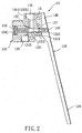
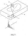
- the first preferred embodiment of a water-saving device 1 is adapted to control water flow to a faucet 21 of a sink 2, and is shown to comprise an inlet hose 11 adapted to supply water to the faucet 21, an outlet hose 12 that is in fluid communication with the faucet 21, and a control assembly 13 connected to the inlet and outlet hoses 11, 12 and adapted to be located upstream of the faucet 21.
- the control assembly 13 includes a housing 131, a plunger 132, an operation unit, and a biasing unit 134.
- the housing 131 has an inlet port 135 that is in fluid communication with the inlet hose 11, an outlet port 136 that is in fluid communication with the outlet hose 12, a passage 1310 extending between and in fluid communication with the inlet and outlet ports 11, 12, and a valve seat 1311 disposed in the passage 1310.
- the plunger 132 is mounted movably within the housing 131, and has a valve portion 1321 to be seated on the valve seat 1311, an end portion 1323 which is opposite to the valve portion 1321 and which extends outwardly of the housing 131, and a stem portion 1324 (see Figure 3) connected between the end portion 1323 and the valve portion 1321.
- the valve port ion 1321 has a tapered section 1322 connected to the stem portion 1324, an enlarged section 1325 (see Figure 3) formed at one side of the tapered section 1322 opposite to the stem portion 1324, and a slanted shoulder 1326 (see Figures 2 and 3) that is connected between the tapered section 1322 and the enlarged section 1325 and that converges from the enlarged section 1325 to the tapered section 1322.
- the housing 131 further has a through hole 1312 (see Figure 3) communicated with the passage 1310 to receive and permit the end portion 1323 of the plunger 132 to extend out of the housing 131, and a wall 1313 (see Figure 3) confining the through hole 1312.
- the end portion 1323 of the plunger 132 is in sliding contact with the wall 1313, and has a sealing ring 1327 (see Figure 3) disposed around the end portion 1323 and between the end portion 1323 and the wall 1313.
- the operation unit is connected to the end portion 1323 of the plunger 132.
- the operation unit includes a lever 133 having a pivot end portion 138 connected pivotally to the housing 131 through a pivot pin 14, a free end 139 opposite to the pivot end portion 138, and a press portion 140 between the pivot end portion 138 and the free end 139 to press the end portion 1323 of the plunger 132.
- the biasing unit 134 is disposed in the housing 131, and biases the valve portion 1321 of the plunger 132.
- the biasing unit 134 is configured as a compression spring, which has a first end 1341 fixed to the housing 131, and a second end 1342 opposite to the first end 1341 and abutting against the valve portion 1321 so as to push the valve portion 1321 against the valve seat 1311 and to push outwardly the end portion 1323 of the plunger 132.
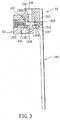
- the plunger 132 can be moved from a closing position shown in Figure 2 to an open position shown in Figure 4.
- the biasing unit 134 moves the valve portion 1321 of the plunger 132 to the closing position in which the valve portion 1321 is seated against the valve seat 1311 of the housing 131 with the slanted shoulder 1326 of the valve portion 1321 in contact with the valve seat 1311, whereas the lever 133 of the operation unit presses the end portion 1323 and moves the valve portion 1321 to the open position in which the valve portion 1321 is moved away from the valve seat 1311.
- the inlet and outlet ports 135, 136 are not in fluid communication with each other so that water cannot pass from the inlet port 135 to the outlet port 136.
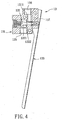
- the inlet and outlet ports 135, 136 are in fluid communication with each other so that water can pass through the inlet port 135, the passage 1310, and into the outlet port 136.
- the space between the tapered section 1322 of the valve portion 1321 of the plunger 132 and the valve seat 1311 of the housing 131 gradually increases, so that the amount of water entering the outlet port 136 also increases, thereby gradually providing a large amount of water outflow.
- the space between the tapered section 1322 of the valve portion 1321 of the plunger 132 and the valve seat 1311 of the housing 131 is at a maximum, so that the amount of water entering the outlet port 136 is the largest, thereby providing the largest amount of water outflow.
- the amount of water entering the outlet port 136 can be controlled by varying the space between the tapered section 1322 of the valve portion 1321 of the plunger 132 and the valve seat 1311 of the housing 131.
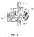
- the control assembly 13 further includes a latch unit 130 disposed on the pivot end portion 138 of the lever 133.
- the housing 131 is formed with a latch hole 137 (see also Figures 2 and 4) between the end portion 1323 of the plunger 132 and the pivot end portion 138 of the lever 133 for receiving the latch unit 130.
- the latch unit 130 includes a latch casing 1303 mounted on the lever 133, and a latch member 1301 disposed movably in the latch casing 1303.
- the latch member 1301 has a head portion 1304 extending into the latch hole 137, a cap 1306 opposite to the head portion 1304, a shank portion 1305 between the head portion 1304 and the cap 1306 and extending out of the latch casing 1303, and a spring member 1302 that is sleeved on the shank portion 1305 between the latch casing 1303 and the cap 1306 and that biases the cap 1306 to move away from the latch casing 1303 when the plunger 132 is moved to the closing position.
- the latch unit 130 is inserted into the latch hole 137, so that the plunger 132 is positioned thereat.
- the faucet 21 When water is desired for washing hands, the faucet 21 is opened first. Then, the user uses his knee or leg to push the free end 139 of the lever 133 toward the housing 131.
- the press portion 140 of the lever 133 pushes the end portion 1323 of the plunger 132 so as to move the plunger 132 to the open position shown in Figure 4.
- the plunger 132 compresses the biasing unit 134 so that the biasing unit 134 can store a restoring force
- the valve portion 1321 of the plunger 132 is moved away from the valve seat 1311 of the housing 131 so that the inlet and outlet ports 135, 136 can communicate fluidly with each other.
- water from the inlet hose 11 flows smoothly through the inlet port 135, the passage 1310, and the outlet port 135, 136, and flows continuously through the outlet hose 12 and out of the faucet 21.
- the user When it is desired to stop the flow of water, the user simply releases the free end 139 of the lever 133.
- the biasing unit 134 releases its restoring force to push the plunger 132 to the closing position shown in Figure 2 so as to block the communication between the inlet and outlet ports 135, 136.
- water from the inlet hose 11 cannot flow through the outlet hose 12, and the faucet 21 stops providing water.
- the user can tightly close the faucet 21 afterwards. Even if the faucet 21 is not tightly closed, water will not flow out of the faucet 21.
- the user may push the latch member 1301 of the latch unit 130 through the cap 1306 and into the latch hole 137 in the housing 131 so as to prevent the plunger 132 from rotating.
- the lever 133 When stoppage of water is desired, the lever 133 is slightly pressed so as to loosen the head portion 1304 from the latch hole 137. The spring member 1302 then biases the cap 1306 to move away from the latch casing 1303 bringing along the head portion 1304 so that the head portion 1304 is moved away from the latch hole 137.
- the lever 133 is not limited at this time so that it can be restored to its original position, and releases its pressing force against the plunger 132.
- the plunger 132 is biased by the biasing unit 134 to move toward the closing position, thereby stopping flow of water through the faucet 21.
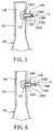
- the second preferred embodiment of a water-saving device 1 is shown to be substantially similar to the first preferred embodiment, and is adapted to be installed on a sink 3.
- the operation unit includes a knob 133' having an internally threaded hole 1331'.
- the end portion 1323 of the plunger 132 is formed with an externally threaded portion 1323' that engages the internally threaded hole 1331' so that the knob 133' is fixed threadedly on the plunger 132.
- the water-saving device 1 of this embodiment is directly fixed to a wall 32 of the sink 3 so that the knob 133' is located externally of the wall 32.
- any part of the user's body can press the knob 133' so that the knob 133' can directly push the plunger 132 to the open position.
- the pressure on the knob 133 is simply released.
- the plunger 132 is moved to the closing position, thereby stopping supply of water.
Landscapes
- Engineering & Computer Science (AREA)
- General Engineering & Computer Science (AREA)
- Mechanical Engineering (AREA)
- Domestic Plumbing Installations (AREA)
- Treatment Of Water By Ion Exchange (AREA)
- Water Treatment By Sorption (AREA)
Claims (7)
- Un dispositif économiseur d'eau (1) pour un robinet de puisage (21), comprenant :un tuyau (11) adapté pour alimenter en eau le robinet de puisage (21) ; etun assemblage de commande (13) connecté sur ledit tuyau (11) et adapté pour être placé en amont du robinet de puisage (21), ledit assemblage de commande (13) incluant:un boîtier (131) ayant un orifice d'alimentation (135), un orifice de décharge (136), un passage (1310) ménagé en libre communication entre lesdits orifices d'alimentation et de décharge (135, 136), et un siège de clapet (1311) disposé dans ledit passage (1310),un piston plongeur (132) monté de manière mobile dans ledit boîtier (131), et ayant une section clapet (1321) s'adaptant sur ledit siège de clapet (1311), et une section d'extrémité (1323) qui se trouve à l'opposé de ladite section clapet (1321) et qui se prolonge à l'extérieur dudit boîtier (131),une unité d'opération connectée sur ladite section d'extrémité (1323) dudit piston plongeur (132), etune unité de déviation (134) disposée dans ledit boîtier (131) et faisant dévier ladite section clapet (1321),en cela que ladite unité de déviation (134) déplace ladite section clapet (1321) vers une position de fermeture dans laquelle ladite section clapet (1321) est appuyée contre ledit siège de clapet (1311), et ladite unité d'opération déplace ladite section clapet (1321) vers une position d'ouverture dans laquelle ladite section clapet (1321) est écartée dudit siège de clapet (1311),ledit dispositif économiseur d'eau étant caractérisé par:ledit piston plongeur (132) ayant une section tige (1324) connectée entre ladite section d'extrémité (1323) et ladite section clapet (1321), ladite section clapet (1321) ayant une section tronconique (1322) connectée à ladite section tige (1324), une section allongée (1325) formée à l'un des côté de ladite section tronconique (1322) à l'opposé de ladite section tige (1324), et un épaulement en oblique (1326) connecté entre ladite section tronconique (1322) et ladite section allongée (1325) et convergeant depuis ladite section allongée (1325) vers ladite section tronconique (1322), ledit épaulement en oblique (1326) étant en contact avec ledit siège de clapet (1311) lorsque ladite section clapet (1321) est en position fermée.
- Le dispositif économiseur d'eau (1) selon la revendication 1, caractérisé en ce que ladite unité de déviation (134) est configurée sous la forme d'un ressort de compression avec une première extrémité (1341) fixée avec ledit boîtier (131) et une seconde extrémité (1342) buttant contre ladite section clapet (1321) de manière à pousser ladite section clapet (1321) contre ledit siège de clapet (1311) et de pousser vers l'extérieur ladite section d'extrémité (1323) dudit piston plongeur (132).
- Le dispositif économiseur d'eau (1) selon la revendication 2, caractérisé en ce que ledit boîtier (131) intègre un trou traversant (1312) communiquant avec ledit passage (1310) pour recevoir et permettre à ladite section d'extrémité (1323) dudit piston plongeur (132) de se prolonger hors dudit boîtier (131), et une paroi (1313) confinant ledit trou traversant (1312), ladite section d'extrémité (1323) étant en contact coulissant avec ladite paroi (1313) et ayant une bague d'étanchéité (1327) disposée autour de ladite section d'extrémité (1323) et entre ladite section d'extrémité (1323) et ladite paroi (1313).
- Le dispositif économiseur d'eau (1) selon la revendication 3, caractérisé en ce que ladite unité d'opération inclut un levier (133) ayant une section d'extrémité pivot (138) connectée de manière à pivoter par rapport avec ledit boîtier (131), une extrémité libre (139) opposée à ladite section d'extrémité pivot (138), et une section de pression (140) disposée entre ladite extrémité libre (139) et ladite section d'extrémité pivot (138) pour presser ladite section d'extrémité (1323) dudit piston plongeur (132).
- Le dispositif économiseur d'eau (1) selon la revendication 4, caractérisé en ce que ledit boîtier (131) est formé avec un trou de gâche (137) entre ladite section d'extrémité (1323) dudit piston plongeur (132) et ladite section d'extrémité pivot (138) dudit levier (133), ledit assemblage de commande (13) incluant en outre une unité de gâche (130) disposée sur ladite section d'extrémité pivot (138), ladite unité de gâche (130) se prolongeant dans ledit trou de gâche (137) lorsque ledit piston plongeur (132) est disposé à ladite position d'ouverture de manière à positionner ledit piston plongeur (132) à cet endroit.
- Le dispositif économiseur d'eau (1) selon la revendication 5, caractérisé en ce que ladite unité de gâche (130) inclut un logement de pêne (1303) monté sur ledit levier (133), et un élément pêne (1301) disposé de manière mobile dans ledit logement de pêne (1303), ledit élément pêne (1301) ayant une section tête (1304) se prolongeant dans ledit trou de gâche (137), un capuchon (1306) à l'opposé de ladite section tête (1304), une section tige (1305) entre ladite section tête (1304) et ledit capuchon (1306) et se prolongeant hors dudit logement de pêne (1303), et un élément ressort (1302) emmanché sur ladite section tige (1305) entre ledit logement de pêne (1303) et ledit capuchon (1306) et faisant dévier ledit capuchon (1306) pour qu'il s'écarte dudit logement de pêne (1303).
- Le dispositif économiseur d'eau (1) selon la revendication 1, caractérisé en ce que ladite unité d'opération est un bouton (133') ayant un trou à filetage intérieur (1331'), ladite section d'extrémité (1323) dudit piston plongeur (132) étant formé avec une section à filetage extérieur (1323') qui s'engage dans le trou à filetage intérieur (1331').
Priority Applications (5)
| Application Number | Priority Date | Filing Date | Title |
|---|---|---|---|
| ES04000390T ES2271705T3 (es) | 2004-01-10 | 2004-01-10 | Dispositivo de ahorro de agua para grifo. |
| AT04000390T ATE337508T1 (de) | 2004-01-10 | 2004-01-10 | Wasser-einsparungsvorrichtung für einen hahn |
| EP04000390A EP1553340B1 (fr) | 2004-01-10 | 2004-01-10 | Dispositif d'économie de l'eau pour un robinet |
| DE602004002082T DE602004002082T2 (de) | 2004-01-10 | 2004-01-10 | Wasser-Einsparungsvorrichtung für einen Hahn |
| HK06100245.7A HK1082787B (zh) | 2004-01-10 | 2006-01-05 | 用於龍頭的節水裝置 |
Applications Claiming Priority (1)
| Application Number | Priority Date | Filing Date | Title |
|---|---|---|---|
| EP04000390A EP1553340B1 (fr) | 2004-01-10 | 2004-01-10 | Dispositif d'économie de l'eau pour un robinet |
Publications (2)
| Publication Number | Publication Date |
|---|---|
| EP1553340A1 EP1553340A1 (fr) | 2005-07-13 |
| EP1553340B1 true EP1553340B1 (fr) | 2006-08-23 |
Family
ID=34585968
Family Applications (1)
| Application Number | Title | Priority Date | Filing Date |
|---|---|---|---|
| EP04000390A Expired - Lifetime EP1553340B1 (fr) | 2004-01-10 | 2004-01-10 | Dispositif d'économie de l'eau pour un robinet |
Country Status (5)
| Country | Link |
|---|---|
| EP (1) | EP1553340B1 (fr) |
| AT (1) | ATE337508T1 (fr) |
| DE (1) | DE602004002082T2 (fr) |
| ES (1) | ES2271705T3 (fr) |
| HK (1) | HK1082787B (fr) |
Family Cites Families (6)
| Publication number | Priority date | Publication date | Assignee | Title |
|---|---|---|---|---|
| US3876178A (en) * | 1973-12-21 | 1975-04-08 | William J Mainer | Pressure release valve |
| JPH077098Y2 (ja) * | 1989-10-24 | 1995-02-22 | 日東工器株式会社 | 空気工具の安全装置 |
| US5386600A (en) * | 1993-04-14 | 1995-02-07 | Gilbert, Sr.; Robert V. | Latching foot pedal actuated tap water flow controller |
| US5358216A (en) * | 1994-02-22 | 1994-10-25 | Jang Fang Shyong | Foot-operated valve |
| DE19753947C2 (de) * | 1997-12-05 | 2000-05-25 | Demirel Benjamin Suleyman | Fußschalter zum Schalten des Wasserflusses einer Wasserentnahmestelle |
| PL195691B1 (pl) * | 2000-06-21 | 2007-10-31 | Zaklad Urzadzen Gazowniczych G | Kurek kulowy i klucz do kurka kulowego |
-
2004
- 2004-01-10 EP EP04000390A patent/EP1553340B1/fr not_active Expired - Lifetime
- 2004-01-10 ES ES04000390T patent/ES2271705T3/es not_active Expired - Lifetime
- 2004-01-10 AT AT04000390T patent/ATE337508T1/de not_active IP Right Cessation
- 2004-01-10 DE DE602004002082T patent/DE602004002082T2/de not_active Expired - Lifetime
-
2006
- 2006-01-05 HK HK06100245.7A patent/HK1082787B/zh not_active IP Right Cessation
Also Published As
| Publication number | Publication date |
|---|---|
| DE602004002082D1 (de) | 2006-10-05 |
| HK1082787B (zh) | 2007-04-04 |
| HK1082787A1 (en) | 2006-06-16 |
| ATE337508T1 (de) | 2006-09-15 |
| DE602004002082T2 (de) | 2006-12-07 |
| EP1553340A1 (fr) | 2005-07-13 |
| ES2271705T3 (es) | 2007-04-16 |
Similar Documents
| Publication | Publication Date | Title |
|---|---|---|
| US7380731B1 (en) | Water sprayer having two water different spraying modes | |
| US8152078B2 (en) | Faucet spray head | |
| US7258322B1 (en) | Manually operated switch for a faucet | |
| WO2006065592A3 (fr) | Verrou de gachette pour nettoyeur haute pression | |
| CA2516714A1 (fr) | Dispositif de commande pour distributeur de fluide | |
| US8251090B2 (en) | Faucet having a pressure release function | |
| CA1322774C (fr) | Douchette d'evier raccorde a un robinet a debit pulse | |
| CA2371753A1 (fr) | Robinet a poussoir | |
| EP3296613B1 (fr) | Robinet pour fluide sous pression | |
| US7011293B2 (en) | Water-saving device for a faucet | |
| EP1553340B1 (fr) | Dispositif d'économie de l'eau pour un robinet | |
| CA2843540C (fr) | Vanne a commande manuelle pour un systeme d'installation de douche | |
| US20010025939A1 (en) | Self-closing water-saving device for faucet | |
| US6345806B1 (en) | Foot-actuated faucet | |
| KR20150088463A (ko) | 앵글밸브 | |
| JP3104431U (ja) | 洗面台装置及びそれ専用の押しバルブ | |
| JP4167791B2 (ja) | 流量調整機能を付加したストレーナ付き止水栓 | |
| CN216200790U (zh) | 一种触发式角阀 | |
| KR200413321Y1 (ko) | 감압형 물분사기 | |
| KR20040012385A (ko) | 샤워기 헤드 | |
| KR200381918Y1 (ko) | 순간지수 자폐식 밸브 | |
| JP3369963B2 (ja) | 弁開閉機構及びガンノズル | |
| KR100739854B1 (ko) | 감압형 물분사기 | |
| RU2350716C1 (ru) | Кран смывной (варианты) | |
| JP2003265350A (ja) | 吐水制御装置 |
Legal Events
| Date | Code | Title | Description |
|---|---|---|---|
| PUAI | Public reference made under article 153(3) epc to a published international application that has entered the european phase |
Free format text: ORIGINAL CODE: 0009012 |
|
| AK | Designated contracting states |
Kind code of ref document: A1 Designated state(s): AT BE BG CH CY CZ DE DK EE ES FI FR GB GR HU IE IT LI LU MC NL PT RO SE SI SK TR |
|
| AX | Request for extension of the european patent |
Extension state: AL LT LV MK |
|
| 17P | Request for examination filed |
Effective date: 20050608 |
|
| GRAP | Despatch of communication of intention to grant a patent |
Free format text: ORIGINAL CODE: EPIDOSNIGR1 |
|
| AKX | Designation fees paid |
Designated state(s): AT BE BG CH CY CZ DE DK EE ES FI FR GB GR HU IE IT LI LU MC NL PT RO SE SI SK TR |
|
| REG | Reference to a national code |
Ref country code: HK Ref legal event code: DE Ref document number: 1082787 Country of ref document: HK |
|
| GRAS | Grant fee paid |
Free format text: ORIGINAL CODE: EPIDOSNIGR3 |
|
| GRAA | (expected) grant |
Free format text: ORIGINAL CODE: 0009210 |
|
| AK | Designated contracting states |
Kind code of ref document: B1 Designated state(s): AT BE BG CH CY CZ DE DK EE ES FI FR GB GR HU IE IT LI LU MC NL PT RO SE SI SK TR |
|
| PG25 | Lapsed in a contracting state [announced via postgrant information from national office to epo] |
Ref country code: IT Free format text: LAPSE BECAUSE OF FAILURE TO SUBMIT A TRANSLATION OF THE DESCRIPTION OR TO PAY THE FEE WITHIN THE PRESCRIBED TIME-LIMIT;WARNING: LAPSES OF ITALIAN PATENTS WITH EFFECTIVE DATE BEFORE 2007 MAY HAVE OCCURRED AT ANY TIME BEFORE 2007. THE CORRECT EFFECTIVE DATE MAY BE DIFFERENT FROM THE ONE RECORDED. Effective date: 20060823 Ref country code: NL Free format text: LAPSE BECAUSE OF FAILURE TO SUBMIT A TRANSLATION OF THE DESCRIPTION OR TO PAY THE FEE WITHIN THE PRESCRIBED TIME-LIMIT Effective date: 20060823 Ref country code: FI Free format text: LAPSE BECAUSE OF FAILURE TO SUBMIT A TRANSLATION OF THE DESCRIPTION OR TO PAY THE FEE WITHIN THE PRESCRIBED TIME-LIMIT Effective date: 20060823 Ref country code: SI Free format text: LAPSE BECAUSE OF FAILURE TO SUBMIT A TRANSLATION OF THE DESCRIPTION OR TO PAY THE FEE WITHIN THE PRESCRIBED TIME-LIMIT Effective date: 20060823 Ref country code: SK Free format text: LAPSE BECAUSE OF FAILURE TO SUBMIT A TRANSLATION OF THE DESCRIPTION OR TO PAY THE FEE WITHIN THE PRESCRIBED TIME-LIMIT Effective date: 20060823 Ref country code: LI Free format text: LAPSE BECAUSE OF FAILURE TO SUBMIT A TRANSLATION OF THE DESCRIPTION OR TO PAY THE FEE WITHIN THE PRESCRIBED TIME-LIMIT Effective date: 20060823 Ref country code: CH Free format text: LAPSE BECAUSE OF FAILURE TO SUBMIT A TRANSLATION OF THE DESCRIPTION OR TO PAY THE FEE WITHIN THE PRESCRIBED TIME-LIMIT Effective date: 20060823 Ref country code: BE Free format text: LAPSE BECAUSE OF FAILURE TO SUBMIT A TRANSLATION OF THE DESCRIPTION OR TO PAY THE FEE WITHIN THE PRESCRIBED TIME-LIMIT Effective date: 20060823 Ref country code: AT Free format text: LAPSE BECAUSE OF FAILURE TO SUBMIT A TRANSLATION OF THE DESCRIPTION OR TO PAY THE FEE WITHIN THE PRESCRIBED TIME-LIMIT Effective date: 20060823 Ref country code: CZ Free format text: LAPSE BECAUSE OF FAILURE TO SUBMIT A TRANSLATION OF THE DESCRIPTION OR TO PAY THE FEE WITHIN THE PRESCRIBED TIME-LIMIT Effective date: 20060823 Ref country code: RO Free format text: LAPSE BECAUSE OF FAILURE TO SUBMIT A TRANSLATION OF THE DESCRIPTION OR TO PAY THE FEE WITHIN THE PRESCRIBED TIME-LIMIT Effective date: 20060823 |
|
| REG | Reference to a national code |
Ref country code: GB Ref legal event code: FG4D |
|
| REG | Reference to a national code |
Ref country code: CH Ref legal event code: EP |
|
| REG | Reference to a national code |
Ref country code: IE Ref legal event code: FG4D |
|
| REF | Corresponds to: |
Ref document number: 602004002082 Country of ref document: DE Date of ref document: 20061005 Kind code of ref document: P |
|
| PG25 | Lapsed in a contracting state [announced via postgrant information from national office to epo] |
Ref country code: SE Free format text: LAPSE BECAUSE OF FAILURE TO SUBMIT A TRANSLATION OF THE DESCRIPTION OR TO PAY THE FEE WITHIN THE PRESCRIBED TIME-LIMIT Effective date: 20061123 Ref country code: DK Free format text: LAPSE BECAUSE OF FAILURE TO SUBMIT A TRANSLATION OF THE DESCRIPTION OR TO PAY THE FEE WITHIN THE PRESCRIBED TIME-LIMIT Effective date: 20061123 Ref country code: BG Free format text: LAPSE BECAUSE OF FAILURE TO SUBMIT A TRANSLATION OF THE DESCRIPTION OR TO PAY THE FEE WITHIN THE PRESCRIBED TIME-LIMIT Effective date: 20061123 |
|
| PG25 | Lapsed in a contracting state [announced via postgrant information from national office to epo] |
Ref country code: IE Free format text: LAPSE BECAUSE OF NON-PAYMENT OF DUE FEES Effective date: 20070110 |
|
| PG25 | Lapsed in a contracting state [announced via postgrant information from national office to epo] |
Ref country code: PT Free format text: LAPSE BECAUSE OF FAILURE TO SUBMIT A TRANSLATION OF THE DESCRIPTION OR TO PAY THE FEE WITHIN THE PRESCRIBED TIME-LIMIT Effective date: 20070125 |
|
| PG25 | Lapsed in a contracting state [announced via postgrant information from national office to epo] |
Ref country code: MC Free format text: LAPSE BECAUSE OF NON-PAYMENT OF DUE FEES Effective date: 20070131 |
|
| NLV1 | Nl: lapsed or annulled due to failure to fulfill the requirements of art. 29p and 29m of the patents act | ||
| REG | Reference to a national code |
Ref country code: CH Ref legal event code: PL |
|
| REG | Reference to a national code |
Ref country code: HK Ref legal event code: GR Ref document number: 1082787 Country of ref document: HK |
|
| REG | Reference to a national code |
Ref country code: ES Ref legal event code: FG2A Ref document number: 2271705 Country of ref document: ES Kind code of ref document: T3 |
|
| EN | Fr: translation not filed | ||
| PLBE | No opposition filed within time limit |
Free format text: ORIGINAL CODE: 0009261 |
|
| STAA | Information on the status of an ep patent application or granted ep patent |
Free format text: STATUS: NO OPPOSITION FILED WITHIN TIME LIMIT |
|
| 26N | No opposition filed |
Effective date: 20070524 |
|
| PG25 | Lapsed in a contracting state [announced via postgrant information from national office to epo] |
Ref country code: FR Free format text: LAPSE BECAUSE OF FAILURE TO SUBMIT A TRANSLATION OF THE DESCRIPTION OR TO PAY THE FEE WITHIN THE PRESCRIBED TIME-LIMIT Effective date: 20070511 Ref country code: GR Free format text: LAPSE BECAUSE OF FAILURE TO SUBMIT A TRANSLATION OF THE DESCRIPTION OR TO PAY THE FEE WITHIN THE PRESCRIBED TIME-LIMIT Effective date: 20061124 |
|
| PG25 | Lapsed in a contracting state [announced via postgrant information from national office to epo] |
Ref country code: EE Free format text: LAPSE BECAUSE OF FAILURE TO SUBMIT A TRANSLATION OF THE DESCRIPTION OR TO PAY THE FEE WITHIN THE PRESCRIBED TIME-LIMIT Effective date: 20060823 |
|
| PG25 | Lapsed in a contracting state [announced via postgrant information from national office to epo] |
Ref country code: FR Free format text: LAPSE BECAUSE OF FAILURE TO SUBMIT A TRANSLATION OF THE DESCRIPTION OR TO PAY THE FEE WITHIN THE PRESCRIBED TIME-LIMIT Effective date: 20060823 |
|
| PG25 | Lapsed in a contracting state [announced via postgrant information from national office to epo] |
Ref country code: CY Free format text: LAPSE BECAUSE OF FAILURE TO SUBMIT A TRANSLATION OF THE DESCRIPTION OR TO PAY THE FEE WITHIN THE PRESCRIBED TIME-LIMIT Effective date: 20060823 Ref country code: LU Free format text: LAPSE BECAUSE OF NON-PAYMENT OF DUE FEES Effective date: 20070110 |
|
| PG25 | Lapsed in a contracting state [announced via postgrant information from national office to epo] |
Ref country code: HU Free format text: LAPSE BECAUSE OF FAILURE TO SUBMIT A TRANSLATION OF THE DESCRIPTION OR TO PAY THE FEE WITHIN THE PRESCRIBED TIME-LIMIT Effective date: 20070224 Ref country code: TR Free format text: LAPSE BECAUSE OF FAILURE TO SUBMIT A TRANSLATION OF THE DESCRIPTION OR TO PAY THE FEE WITHIN THE PRESCRIBED TIME-LIMIT Effective date: 20060823 |
|
| PGFP | Annual fee paid to national office [announced via postgrant information from national office to epo] |
Ref country code: DE Payment date: 20110118 Year of fee payment: 8 Ref country code: IT Payment date: 20110127 Year of fee payment: 8 |
|
| PGFP | Annual fee paid to national office [announced via postgrant information from national office to epo] |
Ref country code: GB Payment date: 20110113 Year of fee payment: 8 Ref country code: ES Payment date: 20110222 Year of fee payment: 8 |
|
| GBPC | Gb: european patent ceased through non-payment of renewal fee |
Effective date: 20120110 |
|
| PG25 | Lapsed in a contracting state [announced via postgrant information from national office to epo] |
Ref country code: DE Free format text: LAPSE BECAUSE OF NON-PAYMENT OF DUE FEES Effective date: 20120801 Ref country code: GB Free format text: LAPSE BECAUSE OF NON-PAYMENT OF DUE FEES Effective date: 20120110 |
|
| REG | Reference to a national code |
Ref country code: DE Ref legal event code: R119 Ref document number: 602004002082 Country of ref document: DE Effective date: 20120801 |
|
| REG | Reference to a national code |
Ref country code: ES Ref legal event code: FD2A Effective date: 20130708 |
|
| PG25 | Lapsed in a contracting state [announced via postgrant information from national office to epo] |
Ref country code: ES Free format text: LAPSE BECAUSE OF NON-PAYMENT OF DUE FEES Effective date: 20120111 |
|
| PG25 | Lapsed in a contracting state [announced via postgrant information from national office to epo] |
Ref country code: IT Free format text: LAPSE BECAUSE OF NON-PAYMENT OF DUE FEES Effective date: 20120110 |