EP1553262B1 - Distribution support for service conduits in a turbofan engine. - Google Patents
Distribution support for service conduits in a turbofan engine. Download PDFInfo
- Publication number
- EP1553262B1 EP1553262B1 EP05300012A EP05300012A EP1553262B1 EP 1553262 B1 EP1553262 B1 EP 1553262B1 EP 05300012 A EP05300012 A EP 05300012A EP 05300012 A EP05300012 A EP 05300012A EP 1553262 B1 EP1553262 B1 EP 1553262B1
- Authority
- EP
- European Patent Office
- Prior art keywords
- ancillaries
- turbojet engine
- casing
- sole plate
- support
- Prior art date
- Legal status (The legal status is an assumption and is not a legal conclusion. Google has not performed a legal analysis and makes no representation as to the accuracy of the status listed.)
- Expired - Lifetime
Links
- 229920001971 elastomer Polymers 0.000 claims description 7
- 239000000806 elastomer Substances 0.000 claims description 7
- 239000000463 material Substances 0.000 claims 1
- 238000011144 upstream manufacturing Methods 0.000 description 12
- 239000002184 metal Substances 0.000 description 7
- 239000012530 fluid Substances 0.000 description 4
- 238000002485 combustion reaction Methods 0.000 description 2
- 239000013536 elastomeric material Substances 0.000 description 2
- 239000000446 fuel Substances 0.000 description 2
- 238000012423 maintenance Methods 0.000 description 2
- 238000004519 manufacturing process Methods 0.000 description 2
- 239000000725 suspension Substances 0.000 description 2
- 230000004069 differentiation Effects 0.000 description 1
- 239000013067 intermediate product Substances 0.000 description 1
- 239000010687 lubricating oil Substances 0.000 description 1
- 230000014759 maintenance of location Effects 0.000 description 1
- 239000003921 oil Substances 0.000 description 1
Images

Classifications
-
- F—MECHANICAL ENGINEERING; LIGHTING; HEATING; WEAPONS; BLASTING
- F01—MACHINES OR ENGINES IN GENERAL; ENGINE PLANTS IN GENERAL; STEAM ENGINES
- F01D—NON-POSITIVE DISPLACEMENT MACHINES OR ENGINES, e.g. STEAM TURBINES
- F01D9/00—Stators
- F01D9/06—Fluid supply conduits to nozzles or the like
- F01D9/065—Fluid supply or removal conduits traversing the working fluid flow, e.g. for lubrication-, cooling-, or sealing fluids
Definitions
- the invention relates to a turbofan engine.
- a turbojet engine comprises, functionally, an air intake shaft, a fan, a compressor, a combustion chamber, a turbine and an exhaust nozzle. These various elements are contained in housings.
- the turbojet engine further comprises, around these housings, an internal secondary flow casing, in the form of a shell for containing, on its outer surface, the secondary air flow.
- the secondary air flow corresponds to the air driven by the blower not entering the compressor.
- This shell comprises opening means in two half-shells, in order to access the heart of the turbojet engine.
- the elements of the turbojet engine located in the enclosure defined by the internal casing of the secondary flow.
- Some fluids necessary for the operation of the turbojet engine such as fuel and oil, must be routed from outside the turbojet engine to its core. These fluids are used in particular to supply the combustion chamber with fuel, the various elements of the engine lubricating oil, various cylinders actuating relief valves, variable compressor timing, driving the game of high pressure turbine casings and low pressure, etc.
- the flow of fluids is carried out by pipes commonly called servitudes.
- the invention particularly relates to the passage of servitudes along the support arms of a turbojet engine housing, said intermediate.
- the figure 1 represents a partial view of a turbojet engine 1 of the prior art.
- the latter comprises, downstream of the fan blade retention casing, the outer shell 2 of a casing, said intermediate, which is traditionally attached to the front suspension of the turbojet engine to an aircraft.
- the intermediate casing also comprises radial arms 3.
- Some easements 6 must be routed, from outside the intermediate casing, to the heart of the turbojet engine 1. This routing is generally along an arm 3 of the intermediate casing, the servitudes 6 opening into the heart of the turbojet engine 1 at the level of of the inner ferrule 4.
- turbojet 1 presented is intended to be mounted on an aircraft whose ground clearance is quite low. His nacelle is flattened in its lower portion and swollen on the sides. For safety reasons, servitudes 6 must not pass in the lower part of turbojet 1, in case of friction on the ground of the latter. They are therefore conveyed along an arm 3 of the intermediate casing spaced from the plane of symmetry - global - vertical turbojet 1.
- the servitudes 6 pass through the outer shell 2 of the intermediate casing and are contained, between the outer shell 2 and the inner shell 4, in an arm 7, ensuring their protection as well as the guiding of the secondary air flow.
- the servitudes 6 are fixed, at the level of the inner shell 4, on a sheet 8, by nuts on each side of the sheet 8.
- the present invention aims to reduce the production costs of the internal casing of the secondary flow, to simplify maintenance of the turbojet and to facilitate access to the heart of the turbojet engine at the passage of servitudes along an arm of the intermediate casing.
- a turbofan engine comprising an outer casing supported by arms, an inner casing to the right of the outer casing and servitudes is characterized in that, in the axis of an arm, is provided on the inner casing, a support receiving servitudes having, on the outer side of the inner casing, a first sole for receiving servitudes.
- Axis here means the axis or direction of the gas flow around the arm.
- the first sole comprises service receiving channels.
- the service distribution support comprises, on the internal side of the inner casing, a second sole for the distribution of servitudes.
- the service receiving channels open on the second flange, which comprises servitude connectors.
- the outer casing comprises a set of easement passage.
- the easement passage assembly comprises a fastening flange, supporting a seal, and an attached bearing sector.
- the seal is of elastomeric material and comprises service passage channels.
- the turbojet comprises a service protection arm mounted between the easement passage assembly and the service distribution support.
- the invention is particularly applicable to an outer casing which is the outer shell of the intermediate casing of a turbojet, and to an inner casing which is the inner shell of the intermediate casing, but the applicant does not intend to limit the scope of its rights to this application.
- the invention further relates, as an intermediate product, a service distribution support for the turbojet engine presented above, comprising a first sole for receiving easements and a second sole for the distribution of easements.
- the facility receiving plate comprises service receiving channels.
- the channels open on the distribution base, which comprises at their point of uncoupling servitude connectors.
- the turbojet engine 10 of the invention comprises, downstream of the fan blade retaining casing, a casing said intermediate casing, which is traditionally attached to the front suspension of the turbojet engine 10 to an aircraft;
- the intermediate casing comprises an outer shell 11, supported radial arms 12, at the foot of which extends, on the downstream side, an inner shell 34, to the right of the outer shell 11.
- the invention particularly relates to the conveyance of servitudes along a radial arm 12 of the intermediate casing.
- the intermediate casing 11 On the intermediate casing 11, to the right of the shell 34, is drilled, from the downstream edge 14 of the intermediate casing 11, a recess 13 generally rectangular.
- the intermediate casing 11 comprises, along the circumference of its downstream edge 14, a channel 28.
- the recess 13 is arranged to receive a set of easement passage 53, comprising a fastening flange 14, supporting a seal 15 for guiding and clamping servitudes, and a part 16 which will be named attached support sector 16.
- the flange 14 is generally in the form of a metal stirrup, comprising a base 17 and two branches 20, 20 ', slightly curved to fit the shape of the intermediate casing 11.
- the base 17 of the flange 14 is arranged to bear on the upstream bottom 19 of the recess 13 of the intermediate casing 11. It comprises a longitudinal shoulder 18 whose projecting portion is on the inner side of the base 17.
- the shoulder 18 is shaped to bear on the inner face of the intermediate casing 11, upstream of the recess 13.
- the flange 14 Between the branches 20, 20 'of the flange 14, on its external side, is mounted a seal 15, here elastomeric material, whose outer surface is at the same level as the outer surface of the flange 14.
- the elastomer seal 15 is pierced with a plurality of radial channels 25 for the passage of easements.
- the flange 14 At its downstream end, the flange 14 comprises, at each of its branches 20, 20 ', a longitudinal shoulder 21, 21', situated at a distance of the outer surface of the flange is smaller than that of the opposite shoulder 18.
- the joint support sector 16 is in the form of a metal plate. It comprises, on its downstream edge, two radial projections 26, 26 'forming a channel 27, arranged to ensure the continuity of the channel 28 of the intermediate casing 11.
- the joint support sector 16 On its upstream edge, the joint support sector 16 comprises a central radial projection 29 having at its outer end two longitudinal fingers 30, 30 ', extending upstream.
- the upstream face 31 of the projection 29 and its fingers 30, 30 ' are shaped to bear on the downstream face and the outer face, respectively, of the elastomer seal 15.
- the joint bearing sector 16 further comprises, on its upstream edge, on either side of the central projection 29, two radial bores 32, 32 'for receiving screws 33, 33', spaced apart from each other. other the same distance as the bores 22, 22 'of the flange 14.
- the mounting of the flange 14, on which the elastomer seal 15 is arranged, and the joint bearing sector 16 in the recess 13 is as follows.
- the flange 14 is mounted in the recess 13, with its base 17 bearing on the upstream bottom 19 of the recess 13 and its shoulder 18 bearing on the inner face of the intermediate casing 11, upstream of the recess 13.
- the lugs 23, 23 ' are in contact with the inner face of the intermediate casing 11, fixed to the latter by screws in their bores 24, 24'.
- the joint support sector 16 is fixed to the flange 14 by the screws 33, 33 'in the bores 22, 22' of the flange 14 through the bores 32, 32 'of the attached bearing sector 16.
- the flange 14, the elastomeric seal 15 and the attached support sector 16 ensure the continuity of the intermediate casing 11, while providing channels 25 of easement passage. They constitute a set of passage of servitudes 53, which makes it possible to ensure the passage of the servitudes through the intermediate casing 11, while tightening them relative to each other, according to the distribution of the channels 25 on the elastomer seal 15. It furthermore ensures the tightness of the assembly, the constraints being forcibly inserted into their channels 25.
- a service distribution support 35 placed at the right of the easement passage assembly 53.
- the support 35 comprises, on the outer side of the ferrule 34, a first sole for receiving servitudes 36 projecting out of the latter.
- the sole 36 has a rounded triangular shape, the base of which is located on the upstream side of the shell 34, at the level of the arm 12, and the top of the downstream side of the shell 34.
- the width of the base corresponding approximately to the transverse width of the arm 12.
- the first flange 36 comprises service receiving channels 37, opening on its outer surface.
- the end of the servitudes 38 comprises a specific tip, composed of an annular seal 40, comprising an annular groove 41.
- the seal 40 is adapted to its receiving channel 37, and is fitted so that its groove 41 is flush with on the surface of the first flange 36.
- Metal plates 42, including adapted recesses 43, are fixed, using screws 44, on the sole 36, their recesses 43 engaging on the grooves 41 of the seals 40 of the easements 38 to block the latter in radial translation.
- an arm 45 for the protection of servitudes is fastened to the sole 36, to the radial support 39, to the flange 14 and to the attached bearing sector 16.
- This arm 45 is in the form of a metal sheet that adapts to the set of elements to which it is attached, in order to protect the whole. Its section is generally constant and corresponds to the contour of the sole plate 36. It is arranged to complete the shape of the arm in order to guide the flow of secondary air flowing between the intermediate casing 11 and the ferrule 34. This form is adapted to the dynamic stresses that are imposed on the flow, and proceeds from parameters mainly related to fluid mechanics.
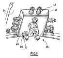
- the service distribution support 35 comprises, on the internal side of the shell, a second sole plate 46 of service distribution, located at the right of the first sole plate 36.
- the reception channels 37 of the servitudes 38 pass through the first sole plate 36, external, and extend into the second distribution sole 46. In the latter, they can be oriented, by a bend 47, so as to lead to a side face of the second sole 46, or not to change direction and lead to the inner face of the second sole 46. They can further change diameter if desired.
- ком ⁇ онент connectors 48 At the open end of the channels 37, on the second flange 46, are arranged servitude connectors 48. These connectors 48 comprise a connector gasket 49, a nozzle 50 and a nut 51 for screwing an easement. Thus, it is possible to connect servitudes 52, provided with ends arranged for this purpose, to the service connections 48 of the second flange 46.
- the passage of the servitudes 38 between the intermediate casing 11 and the ferrule 34 is ensured.
- the servitudes 38 are inserted in the channels 25 of the elastomer seal 15, extend in the chamber formed by the arm 45 and the radial support 39, between the intermediate casing 11 and the ferrule 34, and are inserted into the channels 37 of the service distribution support 35, by their tips 40 adapted for this purpose, at which they are blocked in radial translation by the metal plates 42.
- the channels 37 provide the link with the servitudes 52 of the interior of the shell 34, that is to say, the heart of the turbojet engine 10, which are connected to them by the connectors 48 of the distribution plate 46.
- the channels 25 of the elastomeric seal 15, the channels 37 of the service distribution support 35, the metal plates 42 and the connectors 48 of the second base 46 are dimensioned and shaped according to the easements 38, 52 that they must connect.
- the assembly of the latter is, thanks to the invention, perfectly simplified and standardized.
- the service distribution support 35 can indifferently be formed in one piece with the ferrule 34 or attached thereto.
Landscapes
- Engineering & Computer Science (AREA)
- Physics & Mathematics (AREA)
- Fluid Mechanics (AREA)
- Mechanical Engineering (AREA)
- General Engineering & Computer Science (AREA)
- Structures Of Non-Positive Displacement Pumps (AREA)
- Automatic Cycles, And Cycles In General (AREA)
Description
L'invention concerne un turboréacteur à double flux.The invention relates to a turbofan engine.
Un turboréacteur à double flux comprend, fonctionnellement, une manche d'entrée d'air, une soufflante, un compresseur, une chambre de combustion, une turbine et une tuyère d'échappement. Ces divers éléments sont contenus dans des carters.A turbojet engine comprises, functionally, an air intake shaft, a fan, a compressor, a combustion chamber, a turbine and an exhaust nozzle. These various elements are contained in housings.
Le turboréacteur comprend en outre, autour de ces carters, un carter interne de flux secondaire, se présentant sous la forme d'une coque permettant de contenir, sur sa surface externe, le flux d'air secondaire. Le flux d'air secondaire correspond à l'air entraîné par la soufflante ne pénétrant pas dans le compresseur. Cette coque comprend des moyens d'ouverture en deux demi-coques, afin de pouvoir accéder au coeur du turboréacteur. Par coeur du turboréacteur, on entend les éléments du turboréacteur se situant dans l'enceinte définie par le carter interne du flux secondaire.The turbojet engine further comprises, around these housings, an internal secondary flow casing, in the form of a shell for containing, on its outer surface, the secondary air flow. The secondary air flow corresponds to the air driven by the blower not entering the compressor. This shell comprises opening means in two half-shells, in order to access the heart of the turbojet engine. At the heart of the turbojet engine is meant the elements of the turbojet engine located in the enclosure defined by the internal casing of the secondary flow.
Certains fluides nécessaires au fonctionnement du turboréacteur, tels que le carburant et l'huile, doivent être acheminés depuis l'extérieur du turboréacteur vers son coeur. Ces fluides servent notamment à alimenter la chambre de combustion en carburant, les divers éléments du moteur en huile de lubrification, divers vérins d'actionnement de vannes de décharge, de calage variable du compresseur, de pilotage du jeu des carters de turbine haute pression et basse pression, etc.Some fluids necessary for the operation of the turbojet engine, such as fuel and oil, must be routed from outside the turbojet engine to its core. These fluids are used in particular to supply the combustion chamber with fuel, the various elements of the engine lubricating oil, various cylinders actuating relief valves, variable compressor timing, driving the game of high pressure turbine casings and low pressure, etc.
L'acheminement des fluides est effectué par des canalisations communément appelées servitudes. L'invention concerne particulièrement le passage des servitudes le long des bras de soutien d'un carter du turboréacteur, dit intermédiaire.The flow of fluids is carried out by pipes commonly called servitudes. The invention particularly relates to the passage of servitudes along the support arms of a turbojet engine housing, said intermediate.
La
Certaines servitudes 6 doivent être acheminées, depuis l'extérieur du carter intermédiaire, vers le coeur du turboréacteur 1. Cet acheminement se fait généralement le long d'un bras 3 du carter intermédiaire, les servitudes 6 débouchant dans le coeur du turboréacteur 1 au niveau de la virole interne 4.Some easements 6 must be routed, from outside the intermediate casing, to the heart of the turbojet engine 1. This routing is generally along an
Le turboréacteur 1 présenté est destiné à être monté sur un avion dont la garde au sol est assez basse. Sa nacelle est donc aplatie dans sa portion inférieure et enflée sur les côtés. Pour des raisons de sécurité, les servitudes 6ne doivent pas passer dans la partie basse du turboréacteur 1, en cas de frottement sur le sol de cette dernière. Elles sont donc acheminées le long d'un bras 3 du carter intermédiaire écarté du plan de symétrie - globale - vertical du turboréacteur 1.The turbojet 1 presented is intended to be mounted on an aircraft whose ground clearance is quite low. His nacelle is flattened in its lower portion and swollen on the sides. For safety reasons, servitudes 6 must not pass in the lower part of turbojet 1, in case of friction on the ground of the latter. They are therefore conveyed along an
Les servitudes 6 traversent la virole externe 2 du carter intermédiaire et sont contenues, entre la virole externe 2 et la virole interne 4, dans un bras 7, assurant leur protection ainsi que le guidage du flux d'air secondaire. Les servitudes 6 sont fixées, au niveau de la virole interne 4, sur une tôle 8, par des écrous de chaque côté de la tôle 8.The servitudes 6 pass through the
Ces servitudes 6 sont assez nombreuses, par exemple au nombre de onze, et doivent être guidées dans une zone assez encombrée. Elles ne peuvent de surcroît, dans un plan transversal par rapport à l'axe du turboréacteur, se situer en dehors de la section définie par la projection sur le plan transversal du bras de soutien 3 du carter intermédiaire, pour des raisons aérodynamiques liées au flux d'air secondaire. Il est donc nécessaire de les étaler longitudinalement sur la tôle 8. Du fait notamment de la surface nécessaire au vissage des écrous, la tôle 8 s'étend longitudinalement au-delà de la virole interne 4, et dépasse dans la zone d'ouverture des capots du carter interne du flux secondaire, puisqu'elle ne peut se situer, comme nous l'avons vu, dans le plan de symétrie vertical, contenant la charnière d'ouverture des capots.These easements 6 are quite numerous, for example eleven, and must be guided in a fairly congested area. Moreover, they can not, in a plane transverse to the axis of the turbojet engine, be outside the section defined by the projection on the transverse plane of the
Il est donc nécessaire de pratiquer un évidement sur un capot du carter interne du flux secondaire pour assurer le passage de la tôle 8 lors de l'ouverture ou de la fermeture des capots. La pièce 8 doit être adaptée et compléter cet évidement, afin d'assurer la continuité du guidage du flux d'air entre la virole interne 4 et la surface du carter interne du flux secondaire, au niveau de l'évidement. Les coûts de production dudit carter et de maintenance du turboréacteur en sont d'autant augmentés.It is therefore necessary to make a recess on a cover of the internal casing of the secondary flow to ensure the passage of the sheet 8 when opening or closing the covers. The part 8 must be adapted and complete this recess, to ensure the continuity of the flow guide air between the inner shell 4 and the inner casing surface of the secondary flow, at the recess. The production costs of said crankcase and maintenance of the turbojet engine are increased accordingly.
Un tel agencement est décrit par example dans le document
La présente invention vise à réduire les coûts de production du carter interne du flux secondaire, à simplifier la maintenance du turboréacteur et à faciliter l'accès au coeur du turboréacteur au niveau du passage des servitudes le long d'un bras du carter intermédiaire.The present invention aims to reduce the production costs of the internal casing of the secondary flow, to simplify maintenance of the turbojet and to facilitate access to the heart of the turbojet engine at the passage of servitudes along an arm of the intermediate casing.
Conformément à l'invention un turboréacteur à double flux, comprenant un carter externe supporté par des bras, un carter interne au droit du carter externe et des servitudes est caractérisé par le fait que dans l'axe d'un bras, est ménagé, sur le carter interne, un support de réception de servitudes comportant, du côté externe du carter interne, une première semelle pour la réception de servitudes.According to the invention, a turbofan engine comprising an outer casing supported by arms, an inner casing to the right of the outer casing and servitudes is characterized in that, in the axis of an arm, is provided on the inner casing, a support receiving servitudes having, on the outer side of the inner casing, a first sole for receiving servitudes.
Par axe, on entend ici l'axe ou la direction du flux gazeux autour du bras.Axis here means the axis or direction of the gas flow around the arm.
Ainsi, grâce au support de distribution de servitudes de l'invention, il n'est plus nécessaire d'effectuer une découpe dans le carter interne du flux secondaire du turboréacteur, puisque l'encombrement longitudinal est réduit.Thus, thanks to the service distribution support of the invention, it is no longer necessary to make a cut in the inner casing of the secondary jet of the turbojet, since the longitudinal size is reduced.
De préférence, la première semelle comporte des canaux de réception de servitudes.Preferably, the first sole comprises service receiving channels.
Avantageusement, le support de distribution de servitudes comporte, du côté interne du carter interne, une deuxième semelle pour la distribution de servitudes.Advantageously, the service distribution support comprises, on the internal side of the inner casing, a second sole for the distribution of servitudes.
Avantageusement dans ce cas, les canaux de réception de servitudes débouchent sur la deuxième semelle, qui comporte des raccords de servitudes.Advantageously in this case, the service receiving channels open on the second flange, which comprises servitude connectors.
Dans la forme de réalisation préférée de l'invention, le carter externe comprend un ensemble de passage de servitudes.In the preferred embodiment of the invention, the outer casing comprises a set of easement passage.
De préférence, l'ensemble de passage de servitudes comprend une bride de fixation, supportant un joint, et un secteur d'appui joint.Preferably, the easement passage assembly comprises a fastening flange, supporting a seal, and an attached bearing sector.
De préférence encore, le joint est de matière élastomère et comprend des canaux de passage de servitudes.More preferably, the seal is of elastomeric material and comprises service passage channels.
Avantageusement, le turboréacteur comprend un bras de protection de servitudes monté entre l'ensemble de passage de servitudes et le support de distribution de servitudes.Advantageously, the turbojet comprises a service protection arm mounted between the easement passage assembly and the service distribution support.
L'invention s'applique particulièrement à un carter externe qui est la virole externe du carter intermédiaire d'un turboréacteur, et à un carter interne qui est la virole interne du carter intermédiaire, mais la demanderesse n'entend pas limiter la portée de ses droits à cette application.The invention is particularly applicable to an outer casing which is the outer shell of the intermediate casing of a turbojet, and to an inner casing which is the inner shell of the intermediate casing, but the applicant does not intend to limit the scope of its rights to this application.
L'invention concerne en outre, à titre de produit intermédiaire, un support de distribution de servitudes pour le turboréacteur présenté ci-dessus, comportant une première semelle pour la réception de servitudes et une deuxième semelle pour la distribution de servitudes.The invention further relates, as an intermediate product, a service distribution support for the turbojet engine presented above, comprising a first sole for receiving easements and a second sole for the distribution of easements.
De préférence, la semelle de réception de servitudes comporte des canaux de réception de servitudes.Preferably, the facility receiving plate comprises service receiving channels.
De préférence encore, sur la semelle de réception de servitudes, sont agencées des plaques métalliques de blocage en translation de servitudes.More preferably, on the platform for receiving servitudes, are arranged metal locking plates in translation of easements.
Avantageusement, les canaux débouchent sur la semelle de distribution, qui comporte en leur point de débouchement des raccords de servitudes.Advantageously, the channels open on the distribution base, which comprises at their point of uncoupling servitude connectors.
L'invention sera mieux comprise à l'aide de la description suivante de la forme de réalisation préférée du turboréacteur et du support de distribution de servitudes de l'invention, en référence au dessin annexé, sur lequel :
- la
figure 1 représente une vue schématique partielle en perspective d'un turboréacteur de l'art antérieur ; - la
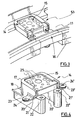
figure 2 représente une vue schématique partielle en perspective du carter intermédiaire de la forme de réalisation préférée du turboréacteur de l'invention ; - la
figure 3 représente une vue schématique partielle en perspective de la virole externe du carter intermédiaire, avec sa bride, son joint élastomère et son secteur d'appui joint, de la forme de réalisation préférée du turboréacteur de l'invention ; - la
figure 4 représente une vue schématique en perspective de la bride et du joint élastomère de la forme de réalisation préférée du turboréacteur de l'invention ; - la
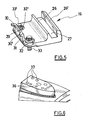
figure 5 représente une vue schématique en perspective du secteur d'appui joint de la forme de réalisation préférée du turboréacteur de l'invention ; - la
figure 6 représente une vue schématique en perspective de la semelle de support de servitudes de la forme de réalisation préférée du support de distribution de servitudes de l'invention ; - la
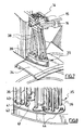
figure 7 représente une vue schématique partielle en perspective de la forme de réalisation préférée du turboréacteur de l'invention, sans son bras de protection de servitudes ; - la
figure 8 représente une vue schématique partielle en perspective de la forme de réalisation préférée du support de distribution de servitudes de l'invention ; - la
figure 9 représente une vue schématique partielle en perspective de la forme de réalisation préférée du turboréacteur de l'invention, avec son bras de protection de servitudes ; - la
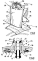
figure 10 représente une vue schématique en coupe de la forme de réalisation préférée du support de distribution de servitudes de l'invention, et - la
figure 11 représente une vue schématique de dessous de la forme de réalisation préférée du support de distribution de servitudes de l'invention.
- the
figure 1 represents a partial schematic perspective view of a turbojet engine of the prior art; - the
figure 2 represents a partial schematic perspective view of the intermediate casing of the preferred embodiment of the turbojet engine of the invention; - the
figure 3 is a partial schematic perspective view of the outer shell of the intermediate casing, with its flange, its elastomeric seal and its attached bearing sector, of the preferred embodiment of the turbojet engine of the invention; - the
figure 4 is a schematic perspective view of the flange and the elastomeric seal of the preferred embodiment of the turbojet engine of the invention; - the
figure 5 is a schematic perspective view of the joint bearing sector of the preferred embodiment of the turbojet engine of the invention; - the
figure 6 is a schematic perspective view of the service support footing of the preferred embodiment of the service delivery support of the invention; - the
figure 7 represents a partial schematic perspective view of the preferred embodiment of the turbojet engine of the invention, without its service protection arm; - the
figure 8 is a partial schematic perspective view of the preferred embodiment of the service delivery support of the invention; - the
figure 9 represents a partial schematic perspective view of the preferred embodiment of the turbojet engine of the invention, with its service protection arm; - the
figure 10 is a schematic sectional view of the preferred embodiment of the service delivery support of the invention, and - the
figure 11 is a schematic bottom view of the preferred embodiment of the service delivery support of the invention.
En référence à la
L'invention concerne particulièrement l'acheminement de servitudes le long d'un bras radial 12 du carter intermédiaire.The invention particularly relates to the conveyance of servitudes along a
Par souci de différentiation des éléments, nous désignerons par la suite la virole externe 11 du carter intermédiaire par l'unique expression de "carter intermédiaire 11" et la virole interne 34 du carter intermédiaire par l'unique terme de "virole 34".For the sake of differentiation of the elements, we will subsequently designate the
Sur le carter intermédiaire 11, au droit de la virole 34, est percé, depuis le bord aval 14 du carter intermédiaire 11, un évidement 13 globalement rectangulaire. Le carter intermédiaire 11 comprend, le long de la circonférence de son bord aval 14, une gouttière 28.On the
En référence à la
Les diverses pièces du turboréacteur de l'invention seront décrites, dans la suite de la description, dans le référentiel du turboréacteur. Ainsi, lorsque les pièces seront représentées, dans une figure, non montées sur le turboréacteur, on désignera leurs diverses portions en fonction de leur placement une fois montées. C'est dans le référentiel du turboréacteur, notamment en fonction de son axe, qu'il faudra comprendre les divers qualificatifs tels que interne, externe, radial, axial, longitudinal, amont, aval, ...The various parts of the turbojet engine of the invention will be described, in the following description, in the reference of the turbojet engine. Thus, when the parts will be shown in a figure, not mounted on the turbojet engine, we will designate their various portions according to their placement once mounted. It is in the reference of the turbojet engine, in particular according to its axis, that it will be necessary to understand the various qualifiers such as internal, external, radial, axial, longitudinal, upstream, downstream, ...
En référence à la
Entre les branches 20, 20' de la bride 14, de son côté externe, est monté un joint 15, ici de matière élastomère, dont la surface externe est au même niveau que la surface externe de la bride 14. Le joint élastomère 15 est percé d'une pluralité de canaux radiaux 25 de passage de servitudes. A son extrémité aval, la bride 14 comprend, au niveau de chacune de ses branches 20, 20', un épaulement longitudinal 21, 21', situé à une distance de la surface externe de la bride plus faible que celle de l'épaulement opposé 18.Between the
Sur les épaulements 21, 21' sont percés, en travers des branches 20, 20', deux alésages radiaux 22, 22' de réception d'une vis. En amont des épaulements 21, 21', deux oreilles 23, 23' font saillie sur les faces latérales des branches 20, 20'. Chaque oreille est percée d'un alésage radial 24, 24'.On the
En référence à la
Sur son bord amont, le secteur d'appui joint 16 comporte une saillie radiale centrale 29 comportant à son extrémité externe deux doigts longitudinaux 30, 30', s'étendant vers l'amont. La face amont 31 de la saillie 29 et ses doigts 30, 30' sont conformés pour venir en appui sur la face aval et la face externe, respectivement, du joint élastomère 15.On its upstream edge, the
Le secteur d'appui joint 16 comporte en outre, sur son bord amont, de part et d'autre de la saillie centrale 29, deux alésages radiaux 32, 32' de réception de vis 33, 33', écartés l'un de l'autre de la même distance que les alésages 22, 22' de la bride 14.The
Le montage de la bride 14, sur laquelle est agencé le joint élastomère 15, et du secteur d'appui joint 16 dans l'évidement 13 est le suivant. La bride 14 est montée dans l'évidement 13, avec sa base 17 en appui sur le fond amont 19 de l'évidement 13 et son épaulement 18 en appui sur la face interne du carter intermédiaire 11, en amont de l'évidement 13. Les oreilles 23, 23' sont en contact avec la face interne du carter intermédiaire 11, fixées à ce dernier par des vis dans leurs alésages 24, 24'. Le secteur d'appui joint 16 est fixé à la bride 14 par les vis 33, 33' dans les alésages 22, 22' de la bride 14 à travers les alésages 32, 32' du secteur d'appui joint 16. La face amont 31 de la saillie 29 et ses doigts 30, 30' sont alors en appui sur la face aval et la face externe du joint élastomère 15 et il y a continuité entre les deux. En outre, dans cette configuration, la gouttière 27 du secteur d'appui joint 16 assure la continuité de la gouttière 28 du carter intermédiaire 11.The mounting of the
Ainsi montés, la bride 14, le joint élastomère 15 et le secteur d'appui joint 16 assurent la continuité du carter intermédiaire 11, tout en fournissant des canaux 25 de passage de servitudes. Ils constituent un ensemble de passage de servitudes 53, qui permet d'assurer le passage des servitudes au travers du carter intermédiaire 11, tout en les resserrant les unes par rapport aux autres, selon la répartition des canaux 25 sur le joint élastomère 15. Il assure en outre l'étanchéité de l'ensemble, les servitudes étant insérées à force dans leurs canaux 25.Thus mounted, the
En référence aux
Le support 35 comprend, du côté externe de la virole 34, une première semelle pour la réception de servitudes 36 faisant saillie hors de cette dernière. La semelle 36 a une forme triangulaire arrondie, dont la base se situe du côté amont de la virole 34, au niveau du bras 12, et le sommet du côté aval de la virole 34. La largeur de la base correspondant environ à la largeur transversale du bras 12. La première semelle 36 comprend des canaux de réception de servitudes 37, débouchant sur sa surface externe.The
Des servitudes 38, provenant de l'extérieur du carter intermédiaire 11, sont insérées dans les canaux 25 du joint élastomère 15, s'étendent le long d'un support radial 39 parallèle au bras 12 monté entre le carter intermédiaire 11 et la virole 34, et leur extrémité est emmanchée dans les canaux 37 de la semelle 36.
En référence à la
En référence à la
En référence aux
A l'extrémité ouverte des canaux 37, sur la deuxième semelle 46, sont agencés des raccords de servitudes 48. Ces raccords 48 comportent un joint de raccord 49, un ajutage 50 et un écrou 51 de vissage d'une servitude. Ainsi, il est possible de connecter des servitudes 52, munies d'embouts agencés à cet effet, aux raccords de servitudes 48 de la deuxième semelle 46.At the open end of the
Grâce à l'invention, le passage des servitudes 38 entre le carter intermédiaire 11 et la virole 34 est assuré. Les servitudes 38 sont insérées dans les canaux 25 du joint élastomère 15, s'étendent dans l'enceinte formée par le bras 45 et le support radial 39, entre le carter intermédiaire 11 et la virole 34, et sont insérés dans les canaux 37 du support de distribution de servitudes 35, par leurs embouts 40 adaptés à cet effet, au niveau desquels elles sont bloquées en translation radiale par les plaques métalliques 42. Les canaux 37 assurent le lien avec les servitudes 52 de l'intérieur de la virole 34, c'est-à-dire le coeur du turboréacteur 10, qui leur sont connectées par les raccords 48 de la semelle de distribution 46.Thanks to the invention, the passage of the
Les canaux 25 du joint élastomère 15, les canaux 37 du support de distribution de servitudes 35, les plaques métalliques 42 et les raccords 48 de la deuxième semelle 46 sont dimensionnés et conformés en fonction des servitudes 38, 52 qu'ils doivent raccorder. Le montage de ces dernières est donc, grâce à l'invention, parfaitement simplifié et standardisé.The
En outre, et notamment du fait que les servitudes 38, 52 ne sont plus fixées par des écrous de part et d'autre de la virole 34 mais emmanchées dans des canaux 37 ou des embouts 48, le gain de place pour leur connexion est grand, et permet d'obtenir un support de distribution de servitudes 35 dont la surface longitudinale ne s'étend pas au-delà de celle de la virole 34. Il n'est donc plus nécessaire de pratiquer un évidement dans les capots du carter interne du flux secondaire, puisque le bras 45, situé au droit du support de distribution de servitudes 35 et notamment de sa première semelle 36, n'empiète pas sur leur zone d'ouverture et de fermeture.In addition, and in particular because the
Le support de distribution de servitudes 35 peut indifféremment être formé d'une seule pièce avec la virole 34 ou rapporté sur cette dernière.The
Claims (14)
- Turbofan jet engine comprising an outer casing (11) supported by arms (12), an inner casing (34) facing the outer casing (11) and ancillaries (38, 52), characterised by the fact that an ancillaries distribution support (35) is formed along the axis of an arm (12), on the inner casing (34), comprising a first sole plate (36) for reception of ancillaries on the outer side of the inner casing (34).
- Turbojet engine according to claim 1, in which the first sole plate (36) comprises ancillaries reception ducts (37).
- Turbojet engine according to one of claims 1 to 2, in which the ancillaries distribution support (35) comprises a second sole plate for the distribution of ancillaries (46) on the inner side of the inner casing (34).
- Turbojet engine according to claims 2 and 3, in which ancillaries reception ducts (37) open up onto the second sole plate (46) that comprises ancillaries fittings (48).
- Turbojet engine according to one of claims 1 to 4, in which the outer casing (11) comprises an ancillaries passage assembly (53).
- Turbojet engine according to claim 5, in which the ancillaries passage assembly (53) comprises an attachment flange (14), supporting a seal (15), and a seal support (16).
- Turbojet engine according to claim 6, in which the seal (15) comprises ancillaries passage ducts (25).
- Turbojet engine according to claim 7, in which the seal (15) is made of an elastomer material.
- Turbojet engine according to one of claims 5 to 8, comprising an ancillaries protection arm (45) installed between the ancillaries passage assembly (53) and the ancillaries distribution support (35).
- Turbojet engine according to one of claims 1 to 9, in which the outer casing is the outer ring of the intermediate casing (11) and the inner casing is the inner ring of the intermediate casing (34).
- Ancillaries distribution support for the turbojet engine in claim 1, comprising a first sole plate for the reception of ancillaries (36) and a second sole plate for the distribution of ancillaries (46).
- Ancillaries distribution support according to claim 11, in which the first sole plate (36) comprises ancillaries reception ducts (37).
- Ancillaries distribution support according to claim 12, in which metallic locking plates (42) fixing the ancillaries in translation are arranged on the first sole plate (36).
- Ancillaries distribution support according to one of claims 12 or 13, in which ducts (37) open up on the second sole plate (46), which comprises ancillaries fittings (48).
Applications Claiming Priority (2)
| Application Number | Priority Date | Filing Date | Title |
|---|---|---|---|
| FR0400222A FR2865002B1 (en) | 2004-01-12 | 2004-01-12 | DOUBLE FLOW TURBOREACTOR COMPRISING A SERVITUDE DISTRIBUTION SUPPORT AND THE SERVITUDE DISTRIBUTION SUPPORT. |
| FR0400222 | 2004-01-12 |
Publications (2)
| Publication Number | Publication Date |
|---|---|
| EP1553262A1 EP1553262A1 (en) | 2005-07-13 |
| EP1553262B1 true EP1553262B1 (en) | 2008-10-01 |
Family
ID=34586488
Family Applications (1)
| Application Number | Title | Priority Date | Filing Date |
|---|---|---|---|
| EP05300012A Expired - Lifetime EP1553262B1 (en) | 2004-01-12 | 2005-01-11 | Distribution support for service conduits in a turbofan engine. |
Country Status (10)
| Country | Link |
|---|---|
| US (1) | US7506499B2 (en) |
| EP (1) | EP1553262B1 (en) |
| JP (1) | JP4081090B2 (en) |
| CN (1) | CN100447397C (en) |
| CA (1) | CA2492171C (en) |
| DE (1) | DE602005009982D1 (en) |
| ES (1) | ES2315820T3 (en) |
| FR (1) | FR2865002B1 (en) |
| RU (1) | RU2365777C2 (en) |
| UA (1) | UA84680C2 (en) |
Families Citing this family (28)
| Publication number | Priority date | Publication date | Assignee | Title |
|---|---|---|---|---|
| CN1671764A (en) * | 2002-07-29 | 2005-09-21 | 住友化学株式会社 | Thermosetting resin composition and adhesive film obtained by forming the composition |
| US20060032974A1 (en) * | 2004-08-16 | 2006-02-16 | Honeywell International Inc. | Modular installation kit for auxiliary power unit |
| FR2875855B1 (en) * | 2004-09-27 | 2006-12-22 | Snecma Moteurs Sa | TURBOREACTOR WITH A MONOBLOC SERVITUDE CONNECTION ARM AND THE MONOBLOC SERVITUDE CONNECTION ARM |
| FR2920195B1 (en) * | 2007-08-23 | 2009-11-20 | Snecma | DOUBLE FLOW TURBOMACHINE WITH JET NOISE REDUCTION |
| FR2925120B1 (en) * | 2007-12-18 | 2010-02-19 | Snecma | INTERMEDIATE CARTER EXTENSION FOR AIRCRAFT TURBOJET ENGINE COMPRISING A SECULATED ANNULAR GROOVE OF RECEPTION OF NACELLE HOODS |
| FR2928961B1 (en) * | 2008-03-19 | 2015-11-13 | Snecma | SECTORIZED DISPENSER FOR A TURBOMACHINE. |
| FR2930592B1 (en) * | 2008-04-24 | 2010-04-30 | Snecma | TURBINE DISPENSER FOR A TURBOMACHINE |
| US20100238270A1 (en) * | 2009-03-20 | 2010-09-23 | Intrepid Management Group, Inc. | Endoscopic apparatus and method for producing via a holographic optical element an autostereoscopic 3-d image |
| US8753075B2 (en) * | 2010-07-20 | 2014-06-17 | Rolls-Royce Corporation | Fan case assembly and method |
| GB2497807B (en) | 2011-12-22 | 2014-09-10 | Rolls Royce Plc | Electrical harness |
| US9478896B2 (en) | 2011-12-22 | 2016-10-25 | Rolls-Royce Plc | Electrical connectors |
| GB2497809B (en) * | 2011-12-22 | 2014-03-12 | Rolls Royce Plc | Method of servicing a gas turbine engine |
| GB2498006B (en) | 2011-12-22 | 2014-07-09 | Rolls Royce Plc | Gas turbine engine systems |
| CA2881774C (en) | 2012-09-26 | 2017-10-24 | United Technologies Corporation | Seal assembly for a static structure of a gas turbine engine |
| FR2999651B1 (en) | 2012-12-18 | 2015-01-16 | Snecma | INTERMEDIATE CARTER EXTENSION WITH IMPROVED DESIGN |
| FR3005992B1 (en) * | 2013-05-24 | 2015-05-22 | Snecma | DEVICE FOR PASSING SERVITUDES FOR A TURBOMACHINE |
| FR3011584B1 (en) * | 2013-10-04 | 2018-02-23 | Safran Aircraft Engines | EXTENSION OF INTERMEDIATE CASING |
| FR3015625B1 (en) * | 2013-12-20 | 2015-12-11 | Snecma | GUIDING ARM FOR EXTENDED SHAPE ELEMENTS, ESPECIALLY FOR A TURBOMACHINE |
| FR3034465B1 (en) * | 2015-04-03 | 2017-05-05 | Snecma | TURBOMOTEUR COMPRISING TWO DISTINCT VENTILATION FLOWS |
| CN105715316B (en) * | 2016-01-26 | 2017-06-27 | 北京航空航天大学 | A simple exhaust frame with an inverted Z-shaped support plate |
| FR3051840B1 (en) * | 2016-05-31 | 2020-01-10 | Safran Aircraft Engines | INTERMEDIATE CRANKCASE OF TURBOMACHINE, EQUIPPED WITH A SEALING PART WITH ARM / CRANK INTERFACE |
| DE102016215030A1 (en) | 2016-08-11 | 2018-02-15 | Rolls-Royce Deutschland Ltd & Co Kg | Turbofan engine with a lying in the secondary flow channel and a separate end element panel |
| RU2642991C1 (en) * | 2017-04-19 | 2018-01-29 | Публичное акционерное общество "ОДК-Уфимское моторостроительное производственное объединение" (ПАО "ОДК-УМПО") | Valve assembly of compressor bypass channel |
| US10800536B2 (en) * | 2017-06-09 | 2020-10-13 | General Electric Company | Propulsion system for an aircraft |
| US10641115B2 (en) | 2017-08-29 | 2020-05-05 | United Technologies Corporation | Segmented conduit with airfoil geometry |
| FR3077846B1 (en) * | 2018-02-14 | 2020-03-13 | Safran Aircraft Engines | INTERIOR HOUSING CRANKCASE FOR DOUBLE FLOW AIRCRAFT TURBOMACHINE, INCLUDING IMPROVED AIRTIGHT AND FIRE RESISTANCE DEVICES |
| FR3086003B1 (en) * | 2018-09-17 | 2020-12-25 | Safran Aircraft Engines | PRIMARY AND SECONDARY FLUID DISTRIBUTION SYSTEM |
| FR3123942B1 (en) * | 2021-06-09 | 2024-02-09 | Safran Aircraft Engines | CURVED FAIRING SUPPORT OF A TURBOMACHINE STRUCTURAL ARM |
Family Cites Families (13)
| Publication number | Priority date | Publication date | Assignee | Title |
|---|---|---|---|---|
| US666854A (en) * | 1900-10-15 | 1901-01-29 | George A Muenzenmaier | Bottle-wrapper machine. |
| US3826088A (en) * | 1973-02-01 | 1974-07-30 | Gen Electric | Gas turbine engine augmenter cooling liner stabilizers and supports |
| US4577891A (en) * | 1983-10-27 | 1986-03-25 | The United States Of America As Represented By The Secretary Of The Air Force | Torque limiting collar |
| US4987736A (en) * | 1988-12-14 | 1991-01-29 | General Electric Company | Lightweight gas turbine engine frame with free-floating heat shield |
| US5174110A (en) * | 1991-10-17 | 1992-12-29 | United Technologies Corporation | Utility conduit enclosure for turbine engine |
| US5292227A (en) * | 1992-12-10 | 1994-03-08 | General Electric Company | Turbine frame |
| DE69704443T2 (en) * | 1996-02-15 | 2001-11-08 | Hispano-Suiza Aerostructures, Gonfreville L'orcher | Thrust reverser for a jet engine with auxiliary flaps connected to the front of the main flaps |
| US5746574A (en) * | 1997-05-27 | 1998-05-05 | General Electric Company | Low profile fluid joint |
| DE19726392A1 (en) * | 1997-06-21 | 1998-12-24 | Bosch Gmbh Robert | Mixture dispenser |
| US6125627A (en) * | 1998-08-11 | 2000-10-03 | Allison Advanced Development Company | Method and apparatus for spraying fuel within a gas turbine engine |
| EP1373386B1 (en) * | 2001-01-10 | 2006-08-16 | Alliant Techsystems Inc. | Fiber-reinforced rocket motor insulation |
| RU2199670C1 (en) * | 2001-07-16 | 2003-02-27 | Открытое Акционерное Общество "А. Люлька-Сатурн" | Adjustable intake guide vane assembly of compressor of gas turbine engine |
| FR2842565B1 (en) * | 2002-07-17 | 2005-01-28 | Snecma Moteurs | INTEGRATED GENERATOR STARTER FOR TURBOMACHINE |
-
2004
- 2004-01-12 FR FR0400222A patent/FR2865002B1/en not_active Expired - Fee Related
-
2005
- 2005-01-10 US US11/030,971 patent/US7506499B2/en active Active
- 2005-01-10 CA CA2492171A patent/CA2492171C/en not_active Expired - Lifetime
- 2005-01-10 UA UAA200500227A patent/UA84680C2/en unknown
- 2005-01-11 EP EP05300012A patent/EP1553262B1/en not_active Expired - Lifetime
- 2005-01-11 JP JP2005003401A patent/JP4081090B2/en not_active Expired - Lifetime
- 2005-01-11 ES ES05300012T patent/ES2315820T3/en not_active Expired - Lifetime
- 2005-01-11 DE DE602005009982T patent/DE602005009982D1/en not_active Expired - Lifetime
- 2005-01-11 RU RU2005100179/06A patent/RU2365777C2/en active
- 2005-01-12 CN CNB2005100041623A patent/CN100447397C/en not_active Expired - Lifetime
Also Published As
| Publication number | Publication date |
|---|---|
| CN1661201A (en) | 2005-08-31 |
| JP4081090B2 (en) | 2008-04-23 |
| FR2865002A1 (en) | 2005-07-15 |
| ES2315820T3 (en) | 2009-04-01 |
| JP2005201267A (en) | 2005-07-28 |
| EP1553262A1 (en) | 2005-07-13 |
| FR2865002B1 (en) | 2006-05-05 |
| DE602005009982D1 (en) | 2008-11-13 |
| CA2492171A1 (en) | 2005-07-12 |
| CA2492171C (en) | 2012-05-01 |
| RU2365777C2 (en) | 2009-08-27 |
| US7506499B2 (en) | 2009-03-24 |
| CN100447397C (en) | 2008-12-31 |
| RU2005100179A (en) | 2006-06-20 |
| US20050247042A1 (en) | 2005-11-10 |
| UA84680C2 (en) | 2008-11-25 |
Similar Documents
| Publication | Publication Date | Title |
|---|---|---|
| CA2492171C (en) | Double flow turbojet engine comprising an ancillaries distribution support and the ancillaries distribution support | |
| EP1640591B1 (en) | Turbojet engine with a monobloc arm for the connexion of subsidiaries | |
| CA2603119C (en) | Device for attaching a stationary blade in a turbine engine annular crankcase, turbojet containing the device and process for assembling the blade | |
| CA2492166C (en) | Turbojet engine comprising an ancillaries connecting arm and the ancillaries connecting arm | |
| FR2885167A1 (en) | TURBINE MODULE FOR GAS TURBINE ENGINE | |
| EP1741879B1 (en) | Apparatus for the support and accomodation of tubes and cables in a turboengine | |
| FR2897144A1 (en) | COMBUSTION CHAMBER FOR TURBOMACHINE WITH TANGENTIAL SLOTS | |
| FR2952701A1 (en) | GUIDING AN IGNITION CANDLE IN A COMBUSTION CHAMBER OF A TURBOMACHINE | |
| EP3945033A1 (en) | Aircraft propulsion unit | |
| FR3020400A1 (en) | FIXING A TURBOMACHINE DISCHARGE DUCT | |
| EP3705686A1 (en) | Turbine engine housing | |
| WO2015082799A1 (en) | Propulsion assembly comprising a box for retaining drained fluids | |
| CA3115013A1 (en) | Suspension assembly for a turbine engine | |
| FR2990001A1 (en) | Intermediate casing for turbojet, has fixing ring for assembling intermediate casing with thrust reverser casing, where fixing ring includes radial annular leg, and heat exchanger is partly fixed to radial annular leg | |
| EP4010564B1 (en) | Assembly aiming to hold a manifold of a cooling device of a casing of a turbine of a turbomachine | |
| FR2961257A1 (en) | Method for mounting discharge valve on hub of intermediate casing of e.g. twin spool turbojet engine of aircraft, involves fixing end-fitting on structure of door for defining air guiding conduit in opening position | |
| WO2021028307A1 (en) | Device for cooling an external casing of a turbomachine and turbomachine provided with such a device | |
| FR2934640A1 (en) | Bearing support trunnion for shaft of turbomachine i.e. twist spool and front fan integrated turbojet engine, has blind lubrication bores, each having opening access unit of channel in bore to pass machining tool for machining opening | |
| EP3969814B1 (en) | Gas turbomachine with combustion chamber attachment | |
| EP3997320B1 (en) | Seal for an intermediate turbomachine casing | |
| EP1700027B1 (en) | Protective housing for an injection system | |
| EP4034752A1 (en) | Assembly for a turbine engine | |
| EP3976947B1 (en) | Notch on a cylinder head inlet surface for oblique attachment on an engine cylinder head | |
| FR2924482A3 (en) | DEVICE FOR CONNECTING TWO PIECES. | |
| FR3140903A1 (en) | Turbomachine intermediate casing |
Legal Events
| Date | Code | Title | Description |
|---|---|---|---|
| PUAI | Public reference made under article 153(3) epc to a published international application that has entered the european phase |
Free format text: ORIGINAL CODE: 0009012 |
|
| 17P | Request for examination filed |
Effective date: 20050107 |
|
| AK | Designated contracting states |
Kind code of ref document: A1 Designated state(s): AT BE BG CH CY CZ DE DK EE ES FI FR GB GR HU IE IS IT LI LT LU MC NL PL PT RO SE SI SK TR |
|
| AX | Request for extension of the european patent |
Extension state: AL BA HR LV MK YU |
|
| RAP1 | Party data changed (applicant data changed or rights of an application transferred) |
Owner name: SNECMA |
|
| AKX | Designation fees paid |
Designated state(s): DE ES FR GB IT |
|
| RTI1 | Title (correction) |
Free format text: DISTRIBUTION SUPPORT FOR SERVICE CONDUITS IN A TURBOFAN ENGINE. |
|
| GRAP | Despatch of communication of intention to grant a patent |
Free format text: ORIGINAL CODE: EPIDOSNIGR1 |
|
| GRAS | Grant fee paid |
Free format text: ORIGINAL CODE: EPIDOSNIGR3 |
|
| GRAA | (expected) grant |
Free format text: ORIGINAL CODE: 0009210 |
|
| AK | Designated contracting states |
Kind code of ref document: B1 Designated state(s): DE ES FR GB IT |
|
| REG | Reference to a national code |
Ref country code: GB Ref legal event code: FG4D Free format text: NOT ENGLISH |
|
| REF | Corresponds to: |
Ref document number: 602005009982 Country of ref document: DE Date of ref document: 20081113 Kind code of ref document: P |
|
| REG | Reference to a national code |
Ref country code: ES Ref legal event code: FG2A Ref document number: 2315820 Country of ref document: ES Kind code of ref document: T3 |
|
| PLBE | No opposition filed within time limit |
Free format text: ORIGINAL CODE: 0009261 |
|
| STAA | Information on the status of an ep patent application or granted ep patent |
Free format text: STATUS: NO OPPOSITION FILED WITHIN TIME LIMIT |
|
| 26N | No opposition filed |
Effective date: 20090702 |
|
| PGFP | Annual fee paid to national office [announced via postgrant information from national office to epo] |
Ref country code: ES Payment date: 20130109 Year of fee payment: 9 |
|
| REG | Reference to a national code |
Ref country code: FR Ref legal event code: PLFP Year of fee payment: 11 |
|
| REG | Reference to a national code |
Ref country code: ES Ref legal event code: FD2A Effective date: 20150406 |
|
| PG25 | Lapsed in a contracting state [announced via postgrant information from national office to epo] |
Ref country code: ES Free format text: LAPSE BECAUSE OF NON-PAYMENT OF DUE FEES Effective date: 20140112 |
|
| REG | Reference to a national code |
Ref country code: FR Ref legal event code: PLFP Year of fee payment: 12 |
|
| REG | Reference to a national code |
Ref country code: FR Ref legal event code: PLFP Year of fee payment: 13 |
|
| REG | Reference to a national code |
Ref country code: FR Ref legal event code: PLFP Year of fee payment: 14 |
|
| REG | Reference to a national code |
Ref country code: FR Ref legal event code: CD Owner name: SAFRAN AIRCRAFT ENGINES Effective date: 20170717 |
|
| PGFP | Annual fee paid to national office [announced via postgrant information from national office to epo] |
Ref country code: GB Payment date: 20231219 Year of fee payment: 20 |
|
| PGFP | Annual fee paid to national office [announced via postgrant information from national office to epo] |
Ref country code: FR Payment date: 20231219 Year of fee payment: 20 |
|
| PGFP | Annual fee paid to national office [announced via postgrant information from national office to epo] |
Ref country code: DE Payment date: 20231219 Year of fee payment: 20 |
|
| PGFP | Annual fee paid to national office [announced via postgrant information from national office to epo] |
Ref country code: IT Payment date: 20240102 Year of fee payment: 20 |
|
| REG | Reference to a national code |
Ref country code: DE Ref legal event code: R071 Ref document number: 602005009982 Country of ref document: DE |
|
| REG | Reference to a national code |
Ref country code: GB Ref legal event code: PE20 Expiry date: 20250110 |
|
| PG25 | Lapsed in a contracting state [announced via postgrant information from national office to epo] |
Ref country code: GB Free format text: LAPSE BECAUSE OF EXPIRATION OF PROTECTION Effective date: 20250110 |