EP1552781B1 - Dishwasher with a rack extraction device. - Google Patents
Dishwasher with a rack extraction device. Download PDFInfo
- Publication number
- EP1552781B1 EP1552781B1 EP04030389A EP04030389A EP1552781B1 EP 1552781 B1 EP1552781 B1 EP 1552781B1 EP 04030389 A EP04030389 A EP 04030389A EP 04030389 A EP04030389 A EP 04030389A EP 1552781 B1 EP1552781 B1 EP 1552781B1
- Authority
- EP
- European Patent Office
- Prior art keywords
- fluid passage
- guide
- drawer
- passage openings
- guide rail
- Prior art date
- Legal status (The legal status is an assumption and is not a legal conclusion. Google has not performed a legal analysis and makes no representation as to the accuracy of the status listed.)
- Expired - Lifetime
Links
- 238000000605 extraction Methods 0.000 title description 2
- 239000012530 fluid Substances 0.000 claims abstract description 173
- 238000005096 rolling process Methods 0.000 claims description 105
- 239000007788 liquid Substances 0.000 claims description 49
- 238000005406 washing Methods 0.000 claims description 4
- 239000000284 extract Substances 0.000 description 12
- 230000002349 favourable effect Effects 0.000 description 9
- 239000002245 particle Substances 0.000 description 9
- 230000000694 effects Effects 0.000 description 7
- 238000011010 flushing procedure Methods 0.000 description 7
- 239000000463 material Substances 0.000 description 7
- 239000007921 spray Substances 0.000 description 6
- 238000004140 cleaning Methods 0.000 description 5
- 238000006073 displacement reaction Methods 0.000 description 5
- 239000000654 additive Substances 0.000 description 4
- 238000000034 method Methods 0.000 description 4
- XLYOFNOQVPJJNP-UHFFFAOYSA-N water Substances O XLYOFNOQVPJJNP-UHFFFAOYSA-N 0.000 description 4
- 238000003698 laser cutting Methods 0.000 description 3
- 230000035515 penetration Effects 0.000 description 2
- 238000004080 punching Methods 0.000 description 2
- 238000000926 separation method Methods 0.000 description 2
- 238000005507 spraying Methods 0.000 description 2
- 229910001220 stainless steel Inorganic materials 0.000 description 2
- 239000010935 stainless steel Substances 0.000 description 2
- 238000004659 sterilization and disinfection Methods 0.000 description 2
- 230000002378 acidificating effect Effects 0.000 description 1
- 230000000996 additive effect Effects 0.000 description 1
- 230000000712 assembly Effects 0.000 description 1
- 238000000429 assembly Methods 0.000 description 1
- 210000001124 body fluid Anatomy 0.000 description 1
- 239000010839 body fluid Substances 0.000 description 1
- 238000005266 casting Methods 0.000 description 1
- 239000002131 composite material Substances 0.000 description 1
- 238000011109 contamination Methods 0.000 description 1
- 238000005260 corrosion Methods 0.000 description 1
- 230000007797 corrosion Effects 0.000 description 1
- 230000006735 deficit Effects 0.000 description 1
- 230000001419 dependent effect Effects 0.000 description 1
- 239000003599 detergent Substances 0.000 description 1
- 239000010794 food waste Substances 0.000 description 1
- 238000001746 injection moulding Methods 0.000 description 1
- 238000009434 installation Methods 0.000 description 1
- 239000000203 mixture Substances 0.000 description 1
- 230000002035 prolonged effect Effects 0.000 description 1
- 230000002000 scavenging effect Effects 0.000 description 1
- 239000000243 solution Substances 0.000 description 1
- 230000001954 sterilising effect Effects 0.000 description 1
- 238000003466 welding Methods 0.000 description 1
Images


Classifications
-
- A—HUMAN NECESSITIES
- A47—FURNITURE; DOMESTIC ARTICLES OR APPLIANCES; COFFEE MILLS; SPICE MILLS; SUCTION CLEANERS IN GENERAL
- A47L—DOMESTIC WASHING OR CLEANING; SUCTION CLEANERS IN GENERAL
- A47L15/00—Washing or rinsing machines for crockery or tableware
- A47L15/42—Details
- A47L15/50—Racks ; Baskets
- A47L15/507—Arrangements for extracting racks, e.g. roller supports
-
- A—HUMAN NECESSITIES
- A47—FURNITURE; DOMESTIC ARTICLES OR APPLIANCES; COFFEE MILLS; SPICE MILLS; SUCTION CLEANERS IN GENERAL
- A47B—TABLES; DESKS; OFFICE FURNITURE; CABINETS; DRAWERS; GENERAL DETAILS OF FURNITURE
- A47B88/00—Drawers for tables, cabinets or like furniture; Guides for drawers
- A47B88/40—Sliding drawers; Slides or guides therefor
- A47B88/49—Sliding drawers; Slides or guides therefor with double extensible guides or parts
-
- F—MECHANICAL ENGINEERING; LIGHTING; HEATING; WEAPONS; BLASTING
- F16—ENGINEERING ELEMENTS AND UNITS; GENERAL MEASURES FOR PRODUCING AND MAINTAINING EFFECTIVE FUNCTIONING OF MACHINES OR INSTALLATIONS; THERMAL INSULATION IN GENERAL
- F16C—SHAFTS; FLEXIBLE SHAFTS; ELEMENTS OR CRANKSHAFT MECHANISMS; ROTARY BODIES OTHER THAN GEARING ELEMENTS; BEARINGS
- F16C29/00—Bearings for parts moving only linearly
- F16C29/04—Ball or roller bearings
Definitions
- the present invention relates to a device having a chamber, the interior of which is at least temporarily flowed through by a liquid or under an elevated pressure gas in the operation of the device, wherein the device at least one extract and at least one pullout guide by means of which the extract along a Extent direction is slidably held on a body of the chamber comprises.
- a device is out of the US-A-5 061 020 known.
- dishwashers with a rinsing chamber are known, the interior of which is at least temporarily traversed by a rinsing liquid (water with cleaning additives) during operation of the dishwasher, wherein the dishwasher comprises at least one extract in the form of a dish rack for receiving the objects to be cleaned.
- the extract can be pulled out of the rinsing chamber and guided by means of rollers on a pair of pull-out guide rails.
- the present invention is therefore an object of the invention to provide a device of the type mentioned above, which even after prolonged operation of the device a precise and smooth leadership of the statement when moving inside the interior or when pulling out of the interior or when inserted into the interior the chamber allows.
- a "pull-out guide” in this description and in the attached claims means any device in which at least two guide rails are held displaceable relative to one another; it is irrelevant whether one of the guide rails is pulled out of the other or not.
- the extension direction can in principle be arbitrarily aligned, in particular substantially horizontally or substantially vertically.
- the pressurized gas may be any gas or gas mixture that is under a pressure that is elevated from ambient, such as air in a jet of compressed air.
- the solution according to the invention is thus based on the concept of using a pull-out guide with rolling-element-mounted guide rails for guiding the pull-out, which guide device is particularly precise and smooth Excerpt when moving inside the interior or when pulling out of the interior or when pushed into the interior of the chamber allows the device.
- At least one of the guide rails and / or at least one WälzMechkafig is provided with the fluid passage openings.
- a particularly good flow through the pull-out guide is achieved when all guide rails of the pullout guide and / or all Wälz stresseshanfige the pullout guide are provided with such fluid passage openings.
- the area ratio of the fluid passage openings of the rolling element cage on the entire surface of the cage back (including the area of the fluid passage openings) in the section provided with the fluid passage openings is at least about 20%.
- the area fraction of the fluid passage openings of the guide rail on the entire surface of the rail back (including the surface of the fluid passage openings) in the section which is provided with the fluid passage openings at least about 25%, preferably at least about 30%, in particular at least about 40%.
- the area fraction of the fluid passage openings of the roller cage on the entire surface of the cage back (including the surface of the fluid passage openings) in the partial section, which is provided with the fluid passage openings at least about 25%, preferably at least about 30% , in particular at least about 40%.
- the surface portion of the fluid passage openings on the entire surface of the rail back or the cage back should not be too large, so that a sufficient mechanical stability of the pullout guide is guaranteed.
- the compatible with a sufficient mechanical stability of the drawer guide upper limit for the surface portion of the fluid passages depends in particular on the geometry of the guide rail profiles, the materials used, the load, the ratio between the length and the extension length of the drawer guide and the connection of the drawer guide the environment, that is in particular the type of attachment of the pullout guide to the boundary walls of the chamber from.
- the area fraction of the fluid passage openings of the guide rail on the entire surface of the rail back (including the surface of the fluid passage openings) in the portion provided with the fluid passage openings at most about 90th %, preferably at most about 80%.
- the area fraction of the fluid passage openings of the roller cage on the entire surface of the cage back (including the surface of the fluid passage openings) in the section which is provided with the fluid passage openings is at most about 90%, preferably at most about 80% , is.
- a framework structure can be introduced into the rail back and / or in the cage back, which allows an optimal flushing behavior under the predetermined mechanical boundary conditions.
- the fluid passage openings can in principle be produced by any method by which the material of the passage openings can be separated out of the surrounding material.
- the fluid passage openings are introduced by punching in the rail back or the cage back.
- the fluid passage openings are introduced by means of a laser cutting process in the guide rail or in the WälzSystemlafig.
- the rail back or the cage back is formed from the outset with the desired fluid passage openings, for example by a casting method (in particular Plastic injection molding) or by assembling the rail back or cage back of several components in such a way that gaps between the composite components give the desired fluid passage openings.
- At least one of the sections provided with fluid passage openings extends over at least one third of the length of the rail back or over at least one third of the length of the cage back.
- the sum of the lengths of the sections of the rail back or of the cage back provided with fluid passage openings is greater than approximately two thirds of the entire length of the rail back or of the cage back.
- the entire rail back or the entire cage back forms a single partial section provided with fluid passage openings, in which area the above-mentioned surface portions of the fluid passage openings are reached.
- the area fraction of the fluid passage openings of the guide rail on the entire surface of the rail back is at least about 20%, preferably at least about 25%, in particular at least about 30%, particularly preferably at least about 40%.
- the surface portion of the fluid passage openings of the rolling element cage on the entire surface of the Caged back at least about 20%, preferably at least about 25%, in particular at least about 30%, more preferably at least about 40%.
- the fluid passage openings come as close as possible to the rolling body raceways of the guide rails, so that on the one hand as little flow losses occur within the pullout guide, so that the liquid jet or the compressed gas jet impinges with as high energy on the residues to be removed and this epicblült, and thus on the other in the field of rolling element tracks no dead water zones arise in which residual liquid or flushing residues can collect.
- the pullout guides can be installed in the chamber both upright (ie with vertically aligned rail backs) and horizontally (ie with horizontally aligned rail backs).
- the optimum installation situation depends on the selected dimension of the rails, the materials used and the loads applied.
- the drawer guide is installed standing, so it is particularly favorable for the drainage of the liquid from the drawer guide, if at least a portion of a guide rail of the drawer guide fluid passage openings having a lower edge whose distance from a lower edge of the rail back of the respective guide rail is smaller than about one quarter of the width of the rail back.
- the extension of the rail back perpendicular to the extension direction is to be understood by the width of the rail back.
- the provided with the fluid passage openings portion of the rail back or the cage back each having at least three substantially mutually congruent fluid passage openings.
- the pullout guide several relatively displaceable components (guide rails and Wälz stresseskorfige) which are each provided with fluid passage openings, the fluid passage openings: different components in certain positions of the pullout guide are aligned and offset in other positions of the pullout guide against each other ,
- the fluid passage openings different components in certain positions of the pullout guide are aligned and offset in other positions of the pullout guide against each other .
- each of the fluid passage openings of the rail back or the cage back of the pullout guide in at least one extension direction has an extension of at most about 5 mm. Such fluid passage openings are then closed small than that one or more fingers could be inserted through aligned fluid passage openings.
- each of the fluid passage openings of the rail back or the cage back along the extension direction has an extension of at most about 5 mm.
- At least one guide rail of the pullout guide and at least one Wälz stresseshanfig the same pullout guide are provided with fluid passage openings.
- fluid passage opening of two juxtaposed fluid passage openings of different components of the pullout guide means any situation in which the fluid passage opening of one component essentially completely covers the relevant fluid passage opening in the other component (seen in a direction perpendicular to the extension direction). For an “alignment” in this sense, it is not necessary that coincide with each other the boundary lines of the two mutually ordered fluid passage openings.
- the edges of fluid passage openings of adjacent components of the drawer slide are offset from each other in the extension direction, that in each case one of the components, the fluid passage openings of the other Baueiements partially, but not completely, covers. In this way it is achieved that the liquid or the gas can enter each region of the drawer guide and that obstacles are formed in the path of the liquid or of the gas, which produce the desired turbulence by the offset edges.
- At least one guide rail of the pullout guide comprises a rolling body track, which is provided with at least one fluid passage opening.
- the WälzSystemonnebahn is provided only in one end region or in both end thereof with one or more fluid passage openings.
- At least one rolling element arrangement of the pullout guide as balls or as spherical rollers, which only touch the WälzConsequentlybahn along a line, formed rolling elements.
- At least one rolling element arrangement of the drawer guide comprises rolling elements which are each in one-point contact with a rolling body raceway of a guide rail of the drawer guide assigned to the rolling elements.
- the rolling elements on the rolling body raceway could also be provided that the rolling elements at two transversely to the extension direction spaced apart locations on the WälzSystemonnebahn issue.
- the area of the rolling body raceway lying between the contact points can be provided with fluid passage openings, so that dirt can be flushed out of the rolling body raceway through these fluid passage openings.
- the pullout guide of the device according to the invention can be designed as a two-part partial pullout, that is to say comprise only the extraction-side guide rail and the body-side guide rail.
- the pullout guide is formed at least three parts and thus comprises at least one further guide rail next to the outgoing guide rail and the body-side guide rail, which is arranged between the extraction-side guide rail and the body-side guide rail.
- Such a pullout guide can be designed, for example, as a multiple pullout (two coupled partial pullouts) or as a telescopic pullout (with a carcass-side guide rail, a middle guide rail displaceable relative thereto and a guide rail which can be displaced in the middle guide rail).
- the drawer guide is designed as a full-drawer guide, by means of which the drawer can be pulled out substantially completely from the interior of the chamber.
- the device according to the invention can be designed, in particular, as a dishwasher or as a washing machine.
- the device according to the invention come into consideration, for example as a disinfection device, sterilization device, flow device or the like, ie all devices which have a chamber which is at least temporarily traversed by a liquid during operation of the device.
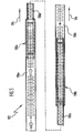
- One in the Fig. 1 and 2 illustrated, as a whole with 100 designated device is designed for example as a dishwasher and comprises a at least temporarily in operation of the device by a liquid, such as water with detergent additives, istströmmbare chamber 102 having an interior 104 which is bounded by a body 106 of the chamber 102 ,
- the body 106 includes a bottom wall 108 from which two parallel vertical side walls 110 and a vertical rear wall 112 connecting the side walls 110 extend upwardly, as well as an upper one Limiting the interior 104 forming ceiling wall 114 and is liquid-tightly closed at its open front by means of a pivotable about a horizontal axis 116 front flap 118.
- the interior 104 of the chamber 102 receives one or more, for example, two, extracts 120, which are formed, for example, as crockery baskets.
- the extracts 120 could be formed, for example, as vats, trays, trays, holders or the like.
- Each of the extracts 120 is held by means of a pullout guide 122 on the two side walls 110 so that it (with open front flap 118) along a substantially horizontal extension direction 124 from the interior 104 extendable or counter to the extension direction 124 completely into the interior 104 of Chamber 102 is inserted.
- the pull-out guides 122 are full-pull guides, which allow the respective associated pull-out 120 to be pulled out substantially completely from the inner space 104 of the chamber 102.
- a plurality, for example two, spray devices 126 are arranged, each comprising one or more rotating about an example vertical axis of rotation 128 spray arms 130, which are each provided with a plurality of spray nozzles 132 which at the top and or are arranged on the underside of the respective spray arm 130 and by means of which a liquid in the Space above or below the respective spray device 126 is sprayed.
- this liquid is the rinsing liquid, which may in particular comprise water with rinsing additives.
- the liquid sprayed during operation of the device 100 is in Fig. 2 indicated by the broken lines 134.
- the sprayed liquid 134 flows through the drains 120 formed, for example, for cleaning purposes, with the articles received therein, for example for cleaning purposes, and optionally through the drawer slides 122, then collects at the bottom of the chamber 102 and flows out of the interior through a drain port (not shown) 104 of the chamber 102 from.
- a first spraying device 126 can be arranged between the bottom wall 108 of the chamber 102 and a lower pullout 120, while a further spraying device 126 can be arranged between two pullouts 120, in particular on the underside of an upper pullout 120.
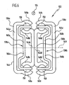
- the guide rails 136 of the pullout guides 122 which by means of Wälzoresan extract 138 along the Extension direction 124 are displaceably guided against each other, each provided with a plurality of fluid passage openings 140 which follow one another along the extension direction 124 and both a penetration of the liquid in the pullout guide 122 and an outflow of liquid (and dirt particles contained therein) from the pullout guide 122 allow as shown schematically in the 3 and 4 is shown.
- Fig. 3 is a pullout guide 122 shown with two guide rails 136 in the extended state.
- Fig. 4 For example, the drawer slide 122 is shown in the fully retracted condition after the apparatus 100 has been put into operation. In this state, the drawer guide 122 is flushed by the sprayed liquid in the interior 104 of the chamber 102, wherein the flow directions of this liquid in Fig. 4 are schematically indicated by the arrows 142.
- the guide rails 136 are preferably formed so that their fluid passage openings 140 in the fully inserted state of the pullout guide 122 with each other and with the fluid passage openings of an in Fig. 4 not shown WälzMechlafigs aligned.
- FIGS Fig. 5 to 11 A concrete example of a pull-out guide 122 with three guide rails, which is particularly suitable for use in a liquid-flow chamber 102, is shown in FIGS Fig. 5 to 11 shown in detail.
- This pullout guide 122 comprises a body-side guide rail 136a (see in particular Fig. 7 ), an extraction side guide rail 136c (see FIG especially Fig. 11 ) and a central guide rail 136b arranged between the body-side guide rail 136a and the extraction-side guide rail 136c (see, in particular, FIG Fig. 9 ).
- the central guide rail 136b is slidably guided by means of a first WälzConsequentlyan extract 138a on the body-side guide rail 136a along the extension direction 124.
- the extraction-side guide rail 136c is displaceably guided along the extension direction 124 by means of a second rolling element arrangement 138b on the middle guide rail 136b.
- the body-side guide rail 136a is in the Fig. 6 and 7 shown in detail.
- the rail back 144a is provided with various mounting holes 152, which is the attachment of the body side Guide rail 136a, in particular the passage of fasteners (for example, screws) through the rail back 144a therethrough serve.
- the rail back 144a is provided with a stopper 153 which cooperates with a rolling element cage 166a of the first rolling element assembly 138a to limit the displacement travel of the first rolling element assembly 138a relative to the body side guide rail 136a.
- the rail back 144a of the body side guide rail 136a in a first portion 154a extending in the extension direction 124 over approximately one third of the length of the body side guide rail 136a, and in a second portion 154b, which is also along the extension direction 124 about a Third of the length of the body side guide rail 136a, provided with a plurality of fluid passage openings 140, which serve the entry and exit of liquid through the body side guide rail 136a in the operation of the device 100.
- the fluid passage openings 140 of the body-side guide rail 136 a are all formed substantially congruent to each other, follow one another along the extension direction 124 and are spaced apart in the extension direction 124.
- Each of the fluid passage openings 140 is formed substantially rectangular, with rounded corner regions.
- the extent 1 of each of the fluid passage openings 140 along the extension direction 124 is approximately 5 mm, while the extent b of each of the fluid passage openings 140 is perpendicular to the extension direction 124 is approximately 16 mm.
- the total width B of the rail spine 144a is approximately 28 mm, and the width L of the web 156 between two successive fluid passage openings 140, ie, its extension along the extension direction 124, is approximately 5 mm.
- the area ratio of the fluid passages 140 on the entire surface of the rail back 144a (including the areas of the fluid passages 140) in the two sections 154a, 154b is about 29%, respectively.
- the distance d of the lower edge of each fluid passage opening 140 from the lower edge of the rail back 144a and the upper edge of each of the fluid passage openings 140 from the upper edge of the rail back 144a is approximately 5 mm, that is approximately 18% of the width B of the rail back 144a.
- the rolling elements 150 which roll on the WälzSystemlaufbahnen 148a of the body-side guide rail 136a are held in a respective receiving hole of an upper and a lower WälzSystemhalteliste 158, wherein both WälzSystemhaltististen 158 parallel to each other and the extension direction 124 extend (see Fig. 8 ).
- Both Wälz stresses 158 are interconnected by means of a cage back 160a, which has a longitudinally extending direction 124 extending portion 162a, which is provided with a plurality of fluid passage openings 164.
- the fluid passage openings 164 are formed substantially congruent with each other, follow each other along the extension direction 124 and are spaced apart in the extension direction 124.
- Each of the fluid passage openings 164 has substantially the shape of a rectangle with attached on two opposite sides of the circle segments.
- each fluid passage opening 164 along the extension direction 124 is approximately 8 mm, while the maximum extent b' of each fluid passage opening 164 perpendicular to the extension direction 124 is approximately 12 mm.
- the width B 'of the cage back 160a is approximately 22 mm, while the width of the web 166 between two successive in the extension direction 124 fluid passage openings 164 is approximately 2 mm.
- the area ratio of the fluid passage openings 164 on the total area of the cage back 160a in the section 162a is approximately 38%.
- the cage back 160a together with the two rolling element retaining strips 158, forms the rolling element cage 166a of the first rolling element arrangement 138a.
- the rolling elements 150 of the first rolling element assembly 138a also roll on two WälzEffbahnen 148b of the central guide rail 136b, each of which one of the WälzEffbahnen 148a of the body side guide rail 136a opposite.
- the two rolling element raceways 148b are connected to each other by a rail back 144b.
- the middle guide rail 136b further includes a further rail back 144b ', which rests with its flat outside on the flat outer side of the rail back 144b and is fixed thereto, for example by welding.
- the rolling element raceways 148b ' are convexly curved (viewed from the longitudinal center plane 149 of the central guide rail 136b) to form a contact surface and a lateral guide for the rolling elements 150 of the second rolling element arrangement 138b.
- the rail back 144 b is in a portion 154 c, which extends over almost the entire length of the rail back 144 b, provided with a plurality of fluid passage openings 140 which follow one another along the extension direction 124 and spaced in the extension direction 124 from each other.
- the fluid passage openings 140 in the rail back 144b are all formed substantially congruent with each other and have a substantially rectangular shape with rounded corners.
- the extent I of each of the fluid passage openings 140 in the extension direction 124 is approximately 5 mm, while the extent b of each of the fluid passage openings 140 perpendicular to the extension direction 124 is approximately 10 mm.
- the width B of the rail back 144 b is about 18 mm, while the width L of the web 156 between each two in the extension direction 124 consecutive fluid passage openings 140, that is, the extension of the web 156 in the extension direction 124, about 5 mm.
- the area ratio of the fluid passage openings 140 on the total area of the rail back 144b in the section 154c is about 28%.
- the distance d of the lower edge of each fluid passage opening 140 from the lower edge of the rail back 144b and the upper edge of each of the fluid passage openings 140 from the upper edge of the rail back 144b is approximately 4 mm, that is approximately 22% of the width B of the rail back 144b.
- the rail back 144b is provided in its rear end with a stop 168 which cooperates with the WälzMechshifig 166a of the first WälzMechan effetive agent 138a to limit the displacement of the central guide rail 136b relative to the first WälzConsequentlyan effetive agent 138a.
- the rail back 144b ' is formed mirror-symmetrically to the rail back 144b and thus also with fluid passage openings 140 and a Stopper 168 'is provided which cooperates with a WälzMechshifig 166b of the second WälzMechan effet 138b to limit the displacement of the second WälzConsequentlyan effet 138b relative to the central guide rail 136b.
- the two rail backs 144b, 144b 'of the central guide rail 136b are fixed to each other so that the fluid passage openings 140 of the rail back 144b in the overlap region of both rail back 144b, 144b' each with a fluid passage opening 140 of the rail back 144b 'are aligned.
- the rolling elements 150 of the second rolling element assembly 138b are formed as balls and in Wälz analysesabilityö Samuelen two Wälz stresses haltelists 158 (see Fig. 10 ), which are interconnected by a cage back 160b and together with the same form the Wälz analyses hisfig 166b of the second Wälz analysesanix 138.
- the cage back 160b is provided in a portion 162b extending over almost the entire length of the cage back 160b with a plurality of fluid passage openings 164 which are substantially congruent with each other, follow one another along the extension direction 124, and are spaced apart in the extension direction 124 ,
- the fluid passage openings 164 of the cage back 160b of the second rolling element arrangement 138b are likewise dimensioned and spaced from each other by the same distance L 'as the fluid passage openings 164 of the cage back 160a of the first rolling element arrangement 138a.
- the cage back 160b has the same width B 'as the cage back 160a of the first one Wälz Scientificanssen 138 a, so that the surface portion of the fluid passage openings 164 on the total surface of the cage back 160 b in the portion 162 b is the same size as in the portion 162 a of the cage back 160 a of the first rolling element assembly 138 a.
- the extraction-side guide rail 136c includes, as best seen Fig. 6 can be seen, two WälzSystemterrorismen 148c, which each one of the WälzSystemlaufbahnen 148b 'of the central guide rail 136b opposite and (seen from the longitudinal center plane 149 of the Ausscheitungsigen guide rail 136c) are concave, so that the WälzConsequentlybahnen 148c of the Ausscheitungsigen guide rail 136c the rolling elements 150 of second Wälzèvean extract 138b provide a contact surface and a lateral guide.
- the rolling element raceways 148c are connected to each other by a rail back 144c ..
- the rail back 144c is provided with mounting holes 174 which serve to receive fastening means by means of which the drawer 120 is connectable to the extraction-side guide rail 136c.
- the rail back 144c has two sections 154d and 154e which extend along the extension direction 124, over approximately one sixth and over approximately two thirds respectively of the length of the rail back 144c.
- Each of the sections 154d, 154e of the rail back 154c has a plurality of fluid passage openings 140 which are substantially congruent are formed with each other, follow one another along the extension direction 124 and are spaced apart in the extension direction 124.
- the fluid passage openings 140 of the rail back 144c are equally dimensioned and spaced from each other by the same distance L in the extension direction 124 as the fluid passage openings 140 of the rail back 144a of the body side guide rail 136a.
- the width B of the rail back 144c agrees with the width B of the rail back 144a of the body side guide rail 136a
- the area ratio of the fluid passage openings 140 on the entire surface of the rail back 144c in the sections 154d and 154e of the rail back 144c is the same in the sections 154a and 154b of the rail back 144a of the body side guide rail 136a.
- each fluid passage opening 140 and the upper edge or the lower edge of the rail back 144c in this embodiment is the same size as in the fluid passage openings 140 of the body side guide rail 136a.
- the guide rails 136a, 136b, and 136c are preferably made of a stainless steel material that provides the advantage of increased corrosion resistance when using deasolvent rinse additive in the liquid used in the interior 104 of the chamber 102. In addition, this material reduces the susceptibility to scavenging residues remaining on the drawer guide 122, particularly acidic or basic food scraps or the like.
- the Wälz stresseskorfige 166a, 166b and the rolling elements 150 are preferably made of a stainless steel material for the reasons mentioned.
- the radii of the spherical rolling elements 150, on the one hand, and the radii of curvature of the rolling element raceways 148a, 148b, 148b 'and 148c, on the other hand, are preferably coordinated so that each rolling element 150 does not touch each rolling element track associated therewith along a line but only at one point.
- the fluid passage openings 140, 164 in the guide rails or the Wälz stressesurafigen can be prepared by any suitable separation method, in particular by punching or by laser cutting.
- the rolling element raceways 148a, 148b, 148b 'and / or 148c are respectively provided in their respective end regions 175 with one or more fluid passage openings 176 having a drain allow residual fluid from the respective rolling body track.
- these passage openings in the end region of a rolling body track can serve to achieve a certain locking effect for one or more rolling elements 150 in an extended position of the pullout guide 122.
- the fluid passage openings 176 are formed in the end portion 175 of the respective Wälz analyseslaufbahn substantially circular and at a distance D from each other, which corresponds to the distance between two rolling elements 150 on one of the Wälz analyses hofige 166a, 166b.
- FIG. 12 A plan view of such an end region 175 with fluid passage openings 176 is shown on the example of the rolling body track 148a of the body-side guide rail 136a in FIG Fig. 12 shown.
Landscapes
- Engineering & Computer Science (AREA)
- General Engineering & Computer Science (AREA)
- Mechanical Engineering (AREA)
- Drawers Of Furniture (AREA)
- Washing And Drying Of Tableware (AREA)
Abstract
Description
Die vorliegende Erfindung betrifft eine Vorrichtung mit einer Kammer, deren Innenraum im Betrieb der Vorrichtung zumindest zeitweise von einer Flüssigkeit oder von einem unter einem erhöhten Druck stehenden Gas durchströmt wird, wobei die Vorrichtung mindestens einen Auszug und mindestens eine Auszugsführung, mittels welcher der Auszug längs einer Auszugsrichtung verschieblich an einem Korpus der Kammer gehalten ist, umfaßt. Solch eine Vorrichtung ist aus der
Solche Vorrichtungen sind aus dem Stand der Technik bekannt.Such devices are known in the art.
Insbesondere sind Geschirrspülmaschinen mit einer Spülkammer bekannt, deren Innenraum im Betrieb der Geschirrspülmaschine zumindest zeitweise von einer Spülflüssigkeit (Wasser mit Reinigungszusätzen) durchströmt wird, wobei die Geschirrspülmaschine mindestens einen Auszug in Form eines Geschirrkorbes zur Aufnahme der zu reinigenden Gegenstände umfaßt. Der Auszug ist aus der Spülkammer herausziehbar und dabei mittels Rollen an einem Paar herausziehbarer Führungsschienen geführt.In particular, dishwashers with a rinsing chamber are known, the interior of which is at least temporarily traversed by a rinsing liquid (water with cleaning additives) during operation of the dishwasher, wherein the dishwasher comprises at least one extract in the form of a dish rack for receiving the objects to be cleaned. The extract can be pulled out of the rinsing chamber and guided by means of rollers on a pair of pull-out guide rails.
Bei diesen Vorrichtungen ist von Nachteil, daß die Führung des Auszugs mittels der Rollen an den ausziehbaren Führungsschienen schwergängig und wenig präzise ist und daß die Führungsschienen dazu neigen, ungleichmäßig aus dem Innenraum der Spülkammer herausgezogen zu werden, was dazu führt, daß der Auszug beim Ausziehen leicht verkantet. Ferner gelangt im Betrieb der Vorrichtung von den zu reinigenden Gegenständen abgespülter Schmutz auf die Laufbahnen der Führungsschienen, wo er von den den Auszug führenden Rollen festgewalzt wird, was die Laufqualität der Rollen auf den Laufbahnen beeinträchtigt.In these devices is a disadvantage that the guide of the drawer by means of the rollers on the extendable guide rails is stiff and not very accurate and that the guide rails tend to be unevenly pulled out of the interior of the washing chamber, which causes the extract when pulling out slightly tilted. Further, in the operation of the device from the objects to be cleaned rinsed dirt on the raceways of the guide rails, where it leads from the extract Rolls is rolled, which affects the running quality of the rollers on the raceways.
Der vorliegenden Erfindung liegt daher die Aufgabe zugrunde, eine Vorrichtung der eingangs genannten Art zu schaffen, welche auch nach längerem Betrieb der Vorrichtung eine präzise und leichtgängige Führung des Auszugs beim Bewegen innerhalb des Innenraums oder beim Herausziehen aus dem Innenraum bzw. beim Einschieben in den Innenraum der Kammer ermöglicht.The present invention is therefore an object of the invention to provide a device of the type mentioned above, which even after prolonged operation of the device a precise and smooth leadership of the statement when moving inside the interior or when pulling out of the interior or when inserted into the interior the chamber allows.
Diese Aufgabe wird bei einer Vorrichtung mit den Merkmalen des Oberbegriffs von Anspruch 1 erfindungsgemäß dadurch gelöst, daß die Auszugsführung mindestens eine auszugsseitige Führungsschiene und eine korpusseitige Führungsschiene und mindestens eine Wälzkörperanordnung umfaßt, mittels welcher eine der Führungsschienen an einer anderen Führungsschiene der Auszugsführung längs der Auszugsrichtung verschieblich geführt ist und welche einen Wälzkörperkäfig umfaßt, wobei
- mindestens eine der Führungsschienen der Auszugsführung einen Schienenrücken umfaßt, der zumindest einen sich längs der Auszugsrichtung erstreckenden Teilabschnitt umfaßt, welcher so mit Fluiddurchtrittsöffnungen versehen ist, daß die betreffende Führungsschiene im Betrieb der Vorrichtung von der Flüssigkeit bzw. von dem Gas durchströmbar ist, und/oder
- mindestens ein Wälzkörperkäfig der Auszugsführung einen Käfigrücken umfaßt, der zumindest einen sich längs der Auszugsrichtung erstreckenden Teilabschnitt umfaßt, welcher so mit Fluiddurchtrittsöffnungen versehen ist, daß der Wälzkörperkäfig im Betrieb der Vorrichtung von der Flüssigkeit bzw. von dem Gas durchströmbar ist.
- at least one of the guide rails of the pullout guide comprises a rail back, which comprises at least one part extending along the extension direction, which is provided with fluid passage openings, that the respective guide rail in the operation of the device from the liquid or from the gas can flow, and / or
- at least one Wälzkörperkäfig the drawer guide comprises a cage back, which comprises at least one extending along the extension direction portion, which thus with fluid passage openings is provided that the Wälzkörperkäfig in the operation of the device from the liquid or from the gas can flow.
Unter dem Schienenrücken einer Führungsschiene ist dabei der zwei Wälzkörperlaufbahnen der Führungsschiene miteinander verbindende Steg zu verstehen. Unter dem Käfigrücken eines Wälzkörperkäfigs ist der zwei Wälzkörperhalteleisten des Wälzkörperkäfigs miteinander verbindende Steg zu verstehen.Under the rail back of a guide rail is the two Wälzkörperlaufbahnen the guide rail interconnecting web to understand. Under the cage back of a Wälzkörperkäfigs the two Wälzkörperhalteleisten the Wälzkörperkäfigs interconnecting web is to be understood.
Unter einem "Auszug" ist in dieser Beschreibung und in den beigefügten Ansprüchen jedes Element zu verstehen, welches durch Relativverschiebung der Führungsschienen innerhalb der Kammer oder aus der Kammer heraus bzw. in die Kammer hinein bewegbar ist.An "extract" in this specification and in the appended claims means any element which is movable by relative displacement of the guide rails within the chamber or out of the chamber or into the chamber.
Unter einer "Auszugsführung" ist in dieser Beschreibung und in den beigefügten Ansprüchen jede Vorrichtung zu verstehen, bei welcher mindestens zwei Führungsschienen relativ zueinander verschieblich gehalten sind; es ist hierbei unerheblich, ob eine der Führungsschienen aus der anderen herausgezogen wird oder nicht.A "pull-out guide" in this description and in the attached claims means any device in which at least two guide rails are held displaceable relative to one another; it is irrelevant whether one of the guide rails is pulled out of the other or not.
Die Auszugsrichtung kann grundsätzlich beliebig ausgerichtet sein, insbesondere im wesentlichen horizontal oder im wesentlichen vertikal.The extension direction can in principle be arbitrarily aligned, in particular substantially horizontally or substantially vertically.
Das unter einem erhöhten Druck stehende Gas kann jedes Gas oder Gasgemisch sein, welches unter einem Druck steht, der gegenüber dem Umgebungsdruck erhöht ist, beispielsweise die Luft in einem Druckluftstrahl.The pressurized gas may be any gas or gas mixture that is under a pressure that is elevated from ambient, such as air in a jet of compressed air.
Der erfindungsgemäßen Lösung liegt somit das Konzept zugrunde, zum Führen des Auszugs eine Auszugsführung mit wälzkörpergelagerten Führungsschienen zu verwenden, welche eine besonders präzise und leichtgängige Führung des Auszugs beim Bewegen innerhalb des Innenraums oder beim Herausziehen aus dem Innenraum bzw. beim Hineinschieben in den Innenraum der Kammer der Vorrichtung ermöglicht.The solution according to the invention is thus based on the concept of using a pull-out guide with rolling-element-mounted guide rails for guiding the pull-out, which guide device is particularly precise and smooth Excerpt when moving inside the interior or when pulling out of the interior or when pushed into the interior of the chamber allows the device.
Dabei ist durch die in den Schienenrücken der Führungsschienen und/oder in den Käfigrücken der Wälzkörperkäfige vorhandenen Fluiddurchtrittsöffnungen, durch welche die die Kammer durchströmende Flüssigkeit bzw. das Gas in die Auszugsführung hinein- und wieder aus der Auszugsführung herausgelangen kann, gewährleistet, daß die Auszugsführung, und zwar insbesondere deren Wälzkörperlaufbahnen, nicht mit Ablagerungen von Schmutzpartikeln zugesetzt und somit unbrauchbar wird, sondern vielmehr von dieser Flüssigkeit bzw. von dem Gas möglichst ungehindert durchspült und aufgrund dieser Durchspülung von Schmutzablagerungen weitgehend freigehalten wird.In this case, it is ensured by the in the rail back of the guide rails and / or in the cage backs of Wälzkörperkäfige fluid passage openings through which the liquid flowing through the chamber or the gas in the drawer guide and can get out of the drawer slide again, that the drawer slide, in particular their Wälzkörperlaufbahnen, not added with deposits of dirt particles and thus unusable, but rather flushed by this liquid or from the gas as freely as possible and largely largely kept free due to this flushing of dirt deposits.
Dieses der Erfindung zugrundeliegende Konzept ist sehr überraschend, da es an sich viel näher liegen würde, eine Verschmutzung der Laufbahnen der Auszugsführung dadurch zu verhindern, daß der Innenraum der Auszugsführung möglichst weitgehend gegen das Eindringen von Flüssigkeit bzw. von Gas aus dem Innenraum der Kammer abgeschottet wird, um so ein Eindringen von Schmutzpartikeln, die die Flüssigkeit bzw. das Gas von den zu reinigenden Gegenständen im Innenraum der Kammer abspült, zu verhindern. Es hat sich nun aber unerwarteterweise herausgestellt, daß das Eindringen von Flüssigkeit bzw. Gas, auch wenn sie bzw. es mit Schmutzpartikeln beladen ist, in die Auszugsführung für die ordnungsgemäße Funktion der Auszugsführung unschädlich ist, sofern nur gewährleistet ist, daß die Flüssigkeit bzw. das Gas mit den darin mitgeführten Schmutzpartikeln auch möglichst ungehindert wieder aus der Auszugsführung herausströmen kann. Auf diese Weise wird verhindert, daß sich Schmutzpartikel in der Auszugsführung, insbesondere auf deren Wälzkörperlaufflächen, ansammeln und so die ordnungsgemäße Funktion der Auszugsführung beeinträchtigen könnten.This concept underlying the invention is very surprising, since it would be much closer to prevent contamination of the tracks of the pullout guide, characterized in that the interior of the pullout guide as far as possible against the ingress of liquid or gas from the interior of the chamber foreclosed is so as to prevent penetration of dirt particles, which rinses the liquid or the gas from the objects to be cleaned in the interior of the chamber. It has now unexpectedly been found that the ingress of liquid or gas, even if it or it is loaded with dirt particles, is harmless in the pullout guide for the proper function of the pullout guide, if only it is ensured that the liquid or the gas with the entrained dirt particles can flow out of the drawer guide as unhindered as possible. In this way it is prevented that dirt particles in the pullout guide, especially on their Rolling surfaces, accumulate and so could affect the proper function of the pullout guide.
Bei der erfindungsgemäßen Vorrichtung ist vorgesehen, daß mindestens eine der Führungsschienen und/oder mindestens ein Wälzkörperkäfig mit den Fluiddurchtrittsöffnungen versehen ist.In the device according to the invention it is provided that at least one of the guide rails and / or at least one Wälzkörperkäfig is provided with the fluid passage openings.
Eine besonders gute Durchströmbarkeit der Auszugsführung wird erreicht, wenn alle Führungsschienen der Auszugsführung und/oder alle Wälzkörperkäfige der Auszugsführung mit solchen Fluiddurchtrittsöffnungen versehen sind.A particularly good flow through the pull-out guide is achieved when all guide rails of the pullout guide and / or all Wälzkörperkäfige the pullout guide are provided with such fluid passage openings.
Besonders günstig ist es, wenn sowohl alle Führungsschienen als auch alle Wälzkörperkäfige der Auszugsführung mit solchen Fluiddurchtrittsöffnungen versehen sind.It is particularly favorable if all guide rails as well as all rolling body cages of the drawer guide are provided with such fluid passage openings.
Sofern neben den Führungsschienen und Wälzkörperkäfigen weitere Anbauelemente vorhanden sind, so sollten auch diese möglichst durchflutungsfreundlich gestaltet sein, um den Flüssigkeitsstrom bzw. den Gasstrom durch die Auszugsführung möglichst wenig zu behindern oder diesen gar zu begünstigen, was insbesondere dann möglich ist, wenn ein im Innenraum der Kammer der Vorrichtung erzeugter Flüssigkeitsstrahl bzw. Druckgasstrahl durch ein entsprechende Gestaltung der Anbauelemente gezielt auf Fluiddurchtrittsöffnungen der Auszugsführung gelenkt wird.If, in addition to the guide rails and Wälzkörperkäfigen more attachments are present, they should be designed as possible flooding friendly to impede the liquid flow or the gas flow through the drawer guide as little as possible or even favor this, which is particularly possible if one in the interior The liquid jet or compressed-gas jet generated in the chamber of the device is directed in a targeted manner onto fluid passage openings of the drawer guide by a corresponding design of the attachment elements.
Versuche an Geschirrspülmaschinen haben bestätigt, daß es für eine effiziente Herausspülung von Reststoffen, insbesondere Schmutzpartikeln, aus der Auszugsführung günstig ist, wenn der Flächenanteil der Fluiddurchtrittsöffnungen der Führungsschiene an der gesamten Fläche des Schienenrückens (einschließlich der Fläche der Fluiddurchtrittsöffnungen) in dem Teilabschnitt, der mit den Fluiddurchtrittsöffnungen versehen ist, mindestens ungefähr 20 % beträgt.Tests on dishwashers have confirmed that it is favorable for an efficient flushing out of residues, in particular dirt particles, from the pull-out guide when the area fraction of the fluid passage openings of the guide rail on the entire surface of the rail back (including the surface of the fluid passages) in the section, which is provided with the fluid passage openings is at least about 20%.
Wenn die Fluiddurchtrittsöffnungen im Käfigrücken eines Wälzkörperkäfigs vorgesehen sind, so hat es sich als günstig erwiesen, wenn der Flächenanteil der Fluiddurchtrittsöffnungen des Wälzkörperkäfigs an der gesamten Fläche des Käfigrückens (einschließlich der Fläche der Fluiddurchtrittsöffnungen) in dem Teilabschnitt, der mit den Fluiddurchtrittsöffnungen versehen ist, mindestens ungefähr 20 % beträgt.When the fluid passage openings are provided in the cage back of a rolling element cage, it has been found to be favorable if the area ratio of the fluid passage openings of the rolling element cage on the entire surface of the cage back (including the area of the fluid passage openings) in the section provided with the fluid passage openings is at least about 20%.
Mit wachsendem Flüssigkeitsdurchsatz bzw. Gasdurchsatz durch die Auszugsführung wird die Reinigungswirkung der durch die Auszugsführung hindurchtretenden Flüssigkeit bzw. des Gases stärker.With increasing liquid flow rate or gas throughput through the drawer guide, the cleaning effect of the liquid or gas passing through the drawer guide becomes stronger.
Es ist daher besonders günstig, wenn der Flächenanteil der Fluiddurchtrittsöffnungen der Führungsschiene an der gesamten Fläche des Schienenrückens (einschließlich der Fläche der Fluiddurchtrittsöffnungen) in dem Teilabschnitt, der mit den Fluiddurchtrittsöffnungen versehen ist, mindestens ungefähr 25 %, vorzugsweise mindestens ungefähr 30 %, insbesondere mindestens ungefähr 40 %, beträgt.It is therefore particularly advantageous if the area fraction of the fluid passage openings of the guide rail on the entire surface of the rail back (including the surface of the fluid passage openings) in the section which is provided with the fluid passage openings, at least about 25%, preferably at least about 30%, in particular at least about 40%.
Alternativ oder ergänzend hierzu ist es besonders günstig, wenn der Flächenanteil der Fluiddurchtrittsöffnungen des Wälzkörperkäfigs an der gesamten Fläche des Käfigrückens (einschließlich der Fläche der Fluiddurchtrittsöffnungen) in dem Teilabschnitt, der mit den Fluiddurchtrittsöffnungen versehen ist, mindestens ungefähr 25 %, vorzugsweise mindestens ungefähr 30 %, insbesondere mindestens ungefähr 40 %, beträgt.Alternatively or additionally, it is particularly favorable if the area fraction of the fluid passage openings of the roller cage on the entire surface of the cage back (including the surface of the fluid passage openings) in the partial section, which is provided with the fluid passage openings, at least about 25%, preferably at least about 30% , in particular at least about 40%.
Andererseits sollte der Flächenanteil der Fluiddurchtrittsöffnungen an der gesamten Fläche des Schienenrückens bzw. des Käfigrückens nicht zu groß werden, damit eine ausreichende mechanische Stabilität der Auszugsführung gewährleistet bleibt.On the other hand, the surface portion of the fluid passage openings on the entire surface of the rail back or the cage back should not be too large, so that a sufficient mechanical stability of the pullout guide is guaranteed.
Die mit einer ausreichenden mechanischen Stabilität der Auszugsführung vereinbare Obergrenze für den Flächenanteil der Fluiddurchtrittsöffnungen hängt insbesondere von der Geometrie der Führungsschienenprofile, von den verwendeten Werkstoffen, von der Beladung, von dem Verhältnis zwischen der Baulänge und der Auszugslänge der Auszugsführung und von der Anbindung der Auszugsführung an die Umgebung, das heißt insbesondere von der Art der Befestigung der Auszugsführung an den Begrenzungswänden der Kammer, ab.The compatible with a sufficient mechanical stability of the drawer guide upper limit for the surface portion of the fluid passages depends in particular on the geometry of the guide rail profiles, the materials used, the load, the ratio between the length and the extension length of the drawer guide and the connection of the drawer guide the environment, that is in particular the type of attachment of the pullout guide to the boundary walls of the chamber from.
Für die Erhaltung einer ausreichenden mechanischen Stabilität der Auszugsführung hat es sich als günstig erwiesen, wenn der Flächenanteil der Fluiddurchtrittsöffnungen der Führungsschiene an der gesamten Fläche des Schienenrückens (einschließlich der Fläche der Fluiddurchtrittsöffnungen) in dem Teilabschnitt, der mit den Fluiddurchtrittsöffnungen versehen ist, höchstens ungefähr 90 %, vorzugsweise höchstens ungefähr 80 %, beträgt.In order to maintain sufficient mechanical stability of the pullout guide, it has proven to be advantageous if the area fraction of the fluid passage openings of the guide rail on the entire surface of the rail back (including the surface of the fluid passage openings) in the portion provided with the fluid passage openings at most about 90th %, preferably at most about 80%.
Alternativ oder ergänzend hierzu ist es von Vorteil, wenn der Flächenanteil der Fluiddurchtrittsöffnungen des Wälzkörperkäfigs an der gesamten Fläche des Käfigrückens (einschließlich der Fläche der Fluiddurchtrittsöffnungen) in dem Teilabschnitt, der mit den Fluiddurchtrittsöffnungen versehen ist, höchstens ungefähr 90 %, vorzugsweise höchstens ungefähr 80 %, beträgt.Alternatively or additionally, it is advantageous if the area fraction of the fluid passage openings of the roller cage on the entire surface of the cage back (including the surface of the fluid passage openings) in the section which is provided with the fluid passage openings, at most about 90%, preferably at most about 80% , is.
Insbesondere kann eine Fachwerkstruktur in den Schienenrücken und/oder in den Käfigrücken eingebracht werden, die ein optimales Durchspülungsverhalten unter den vorgegebenen mechanischen Randbedingungen zuläßt.In particular, a framework structure can be introduced into the rail back and / or in the cage back, which allows an optimal flushing behavior under the predetermined mechanical boundary conditions.
Die Fluiddurchtrittsöffnungen können grundsätzlich durch jedes beliebige Verfahren, durch welches das Material der Durchtrittsöffnungen aus dem umgebenden Material heraustrennbar ist, hergestellt werden.The fluid passage openings can in principle be produced by any method by which the material of the passage openings can be separated out of the surrounding material.
Insbesondere kann vorgesehen sein, daß die Fluiddurchtrittsöffnungen durch Ausstanzen in den Schienenrücken bzw. den Käfigrücken eingebracht werden.In particular, it can be provided that the fluid passage openings are introduced by punching in the rail back or the cage back.
Um besonders hohe Öffnungsverhältnisse erzielen zu können, ohne daß Verwerfungen in der Führungsschiene bzw. in dem Wälzkörperkäfig auftreten, ist es jedoch günstig, die Fluiddurchtrittsöffnungen durch ein kräftefreies Trennverfahren in die Führungsschiene bzw. in den Wälzkörperkäfig einzubringen.In order to achieve particularly high opening ratios, without faults occurring in the guide rail or in the Wälzkörperkäfig, it is advantageous to introduce the fluid passage openings by a force-free separation process in the guide rail or in the Wälzkörperkäfig.
Insbesondere kann vorgesehen sein, daß die Fluiddurchtrittsöffnungen mittels eines Laserschneidverfahrens in die Führungsschiene bzw. in den Wälzkörperkäfig eingebracht werden.In particular, it can be provided that the fluid passage openings are introduced by means of a laser cutting process in the guide rail or in the Wälzkörperkäfig.
Durch ein solches Laserschneidverfahren sind ohne weiteres Flächenanteile der Fluiddurchtrittsöffnungen im Bereich von ungefähr 80 % bis ungefähr 90 % erzielbar.By means of such a laser cutting method, surface portions of the fluid passage openings in the range from approximately 80% to approximately 90% can be readily achieved.
Statt die Fluiddurchtrittsöffnungen aus dem Schienenrücken bzw. Käfigrücken herauszutrennen, kann auch vorgesehen sein, daß der Schienenrücken bzw. der Käfigrücken von vornherein mit den gewünschten Fluiddurchtrittsöffnungen gebildet wird, beispielsweise durch ein Gießverfahren (insbesondere ein Kunststoff-Spritzgießverfahren) oder durch Zusammensetzen des Schienenrückens bzw. Käfigrückens aus mehreren Bestandteilen in der Weise, daß Zwischenräume zwischen den zusammengesetzten Bestandteilen die gewünschten Fluiddurchtrittsöffnungen ergeben.Instead of separating the fluid passage openings from the back of the rail or cage back, it can also be provided that the rail back or the cage back is formed from the outset with the desired fluid passage openings, for example by a casting method (in particular Plastic injection molding) or by assembling the rail back or cage back of several components in such a way that gaps between the composite components give the desired fluid passage openings.
Um einen möglichst hohen Flüssigkeitsdurchsatz bzw. Gasdurchsatz durch die Auszugsführung zu erzielen, ist es von Vorteil, wenn sich mindestens einer der mit Fluiddurchtrittsöffnungen versehenen Teilabschnitte über mindestens ein Drittel der Länge des Schienenrückens bzw. über mindestens ein Drittel der Länge des Käfigrückens erstreckt.In order to achieve the highest possible liquid throughput or gas throughput through the drawer guide, it is advantageous if at least one of the sections provided with fluid passage openings extends over at least one third of the length of the rail back or over at least one third of the length of the cage back.
Ferner ist es günstig, wenn die Summe der Längen der mit Fluiddurchtrittsöffnungen versehenen Teilabschnitte des Schienenrückens bzw. des Käfigrückens größer ist als ungefähr zwei Drittel der gesamten Länge des Schienenrückens bzw. des Käfigrückens.Furthermore, it is favorable if the sum of the lengths of the sections of the rail back or of the cage back provided with fluid passage openings is greater than approximately two thirds of the entire length of the rail back or of the cage back.
Besonders günstig ist es, wenn der gesamte Schienenrücken bzw. der gesamte Käfigrücken einen einzigen mit Fluiddurchtrittsöffnungen versehenen Teilabschnitt bildet, in welchem die vorstehend genannten Flächenanteile der Fluiddurchtrittsöffnungen erreicht werden.It is particularly favorable if the entire rail back or the entire cage back forms a single partial section provided with fluid passage openings, in which area the above-mentioned surface portions of the fluid passage openings are reached.
In diesem Fall beträgt also der Flächenanteil der Fluiddurchtrittsöffnungen der Führungsschiene an der gesamten Fläche des Schienenrückens (einschließlich der Fläche der Fluiddurchtrittsöffnungen) mindestens ungefähr 20 %, vorzugsweise mindestens ungefähr 25 %, insbesondere mindestens ungefähr 30 %, besonders bevorzugt mindestens ungefähr 40 %.In this case, the area fraction of the fluid passage openings of the guide rail on the entire surface of the rail back (including the surface of the fluid passage openings) is at least about 20%, preferably at least about 25%, in particular at least about 30%, particularly preferably at least about 40%.
Alternativ oder ergänzend hierzu beträgt in diesem Fall der Flächenanteil der Fluiddurchtrittsöffnungen des Wälzkörperkäfigs an der gesamten Fläche des Käfigrückens (einschließlich der Fläche der Fluiddurchtrittsöffnungen) mindestens ungefähr 20 %, vorzugsweise mindestens ungefähr 25 %, insbesondere mindestens ungefähr 30 %, besonders bevorzugt mindestens ungefähr 40 %.Alternatively or additionally, in this case, the surface portion of the fluid passage openings of the rolling element cage on the entire surface of the Caged back (including the surface of the fluid passage openings) at least about 20%, preferably at least about 25%, in particular at least about 30%, more preferably at least about 40%.
Grundsätzlich ist es von Vorteil, wenn die Fluiddurchtrittsöffnungen so nahe wie möglich an die Wälzkörperlaufbahnen der Führungsschienen heranreichen, damit zum einen möglichst wenig Strömungsverluste innerhalb der Auszugsführung entstehen, so daß der Flüssigkeitsstrahl bzw. der Druckgasstrahl mit möglichst hoher Energie auf die abzutragenden Rückstände auftrifft und diese fortspült, und damit zum anderen im Bereich der Wälzkörperlaufbahnen keine Totwasserzonen entstehen, in denen sich Restflüssigkeit oder Spülrückstände sammeln können.In principle, it is advantageous if the fluid passage openings come as close as possible to the rolling body raceways of the guide rails, so that on the one hand as little flow losses occur within the pullout guide, so that the liquid jet or the compressed gas jet impinges with as high energy on the residues to be removed and this weiterblült, and thus on the other in the field of rolling element tracks no dead water zones arise in which residual liquid or flushing residues can collect.
Es ist daher von Vorteil, wenn mindestens ein Teilabschnitt einer Führungsschiene der Auszugsführung Fluiddurchtrittsöffnungen aufweist, deren seitlicher Abstand von mindestens einem der seitlichen Ränder des Schienenrückens der betreffenden Führungsschiene kleiner ist als ungefähr ein Viertel der Breite des Schienenrückens.It is therefore advantageous if at least a portion of a guide rail of the pullout guide fluid passage openings whose lateral distance from at least one of the lateral edges of the rail back of the respective guide rail is smaller than approximately one quarter of the width of the rail back.
Die Auszugsführungen können in der Kammer sowohl stehend (das heißt mit vertikal ausgerichteten Schienenrücken) als auch liegend (das heißt mit horizontal ausgerichteten Schienenrücken) eingebaut werden. Die optimale Einbausituation ist von der gewählten Dimension der Schienen, von den eingesetzten Materialien und von den anliegenden Belastungen abhängig.The pullout guides can be installed in the chamber both upright (ie with vertically aligned rail backs) and horizontally (ie with horizontally aligned rail backs). The optimum installation situation depends on the selected dimension of the rails, the materials used and the loads applied.
Wenn die Auszugsführung stehend eingebaut wird, so ist es für das Ablaufen der Flüssigkeit aus der Auszugsführung besonders günstig, wenn mindestens ein Teilabschnitt einer Führungsschiene der Auszugsführung Fluiddurchtrittsöffnungen mit einem unteren Rand aufweist, dessen Abstand von einem unteren Rand des Schienenrückens der betreffenden Führungsschiene kleiner ist als ungefähr ein Viertel der Breite des Schienenrückens.If the drawer guide is installed standing, so it is particularly favorable for the drainage of the liquid from the drawer guide, if at least a portion of a guide rail of the drawer guide fluid passage openings having a lower edge whose distance from a lower edge of the rail back of the respective guide rail is smaller than about one quarter of the width of the rail back.
Dabei ist unter der Breite des Schienenrückens die Ausdehnung des Schienenrückens senkrecht zur Auszugsrichtung zu verstehen.In this case, the extension of the rail back perpendicular to the extension direction is to be understood by the width of the rail back.
Bei einer bevorzugten Ausgestaltung der erfindungsgemäßen Vorrichtung ist vorgesehen, daß der mit den Fluiddurchtrittsöffnungen versehene Teilabschnitt des Schienenrückens bzw. des Käfigrückens jeweils mindestens drei im wesentlichen miteinander kongruente Fluiddurchtrittsöffnungen aufweist.In a preferred embodiment of the device according to the invention it is provided that the provided with the fluid passage openings portion of the rail back or the cage back each having at least three substantially mutually congruent fluid passage openings.
Da bei bevorzugten Ausführungsformen der erfindungsgemäßen Vorrichtung die Auszugsführung mehrere relativ zueinander verschiebbare Bauelemente (Führungsschienen und Wälzkörperkäfige) aufweist, die jeweils mit Fluiddurchtrittsöffnungen versehen sind, wobei die Fluiddurchtrittsöffnungen:verschiedener Bauelemente in bestimmten Stellungen der Auszugsführung miteinander fluchten und in anderen Stellungen der Auszugsführung gegeneinander versetzt sind, besteht grundsätzlich die Gefahr, daß Bedienungspersonen, insbesondere Kinder, mit einem oder mehreren Fingern in miteinander fluchtende Fluiddurchtrittsöffnungen hineingreifen und der bzw. die Finger bei einer anschließender Relativverschiebung der Bauelemente der Auszugsführung gequetscht werden.Since in preferred embodiments of the device according to the invention the pullout guide several relatively displaceable components (guide rails and Wälzkörperkäfige) which are each provided with fluid passage openings, the fluid passage openings: different components in certain positions of the pullout guide are aligned and offset in other positions of the pullout guide against each other , There is a fundamental risk that operators, especially children, reach into one another with one or more fingers into aligned fluid passage openings and the finger or are squeezed in a subsequent relative displacement of the components of the pullout guide.
Um diese Gefahr auszuschließen, ist es von Vorteil, wenn jede der Fluiddurchtrittsöffnungen des Schienenrückens bzw. des Käfigrückens der Auszugsführung in mindestens einer Erstreckungsrichtung eine Ausdehnung von höchstens ungefähr 5 mm aufweist. Solche Fluiddurchtrittsöffnungen sind dann zu klein, als daß ein oder gar mehrere Finger durch miteinander fluchtende Fluiddurchtrittsöffnungen hindurchgesteckt werden könnten.To exclude this risk, it is advantageous if each of the fluid passage openings of the rail back or the cage back of the pullout guide in at least one extension direction has an extension of at most about 5 mm. Such fluid passage openings are then closed small than that one or more fingers could be inserted through aligned fluid passage openings.
Als besonders günstig hat es sich erwiesen, wenn jede der Fluiddurchtrittsöffnungen des Schienenrückens bzw. des Käfigrückens längs der Auszugsrichtung eine Ausdehnung von höchstens ungefähr 5 mm aufweist.It has proven to be particularly favorable when each of the fluid passage openings of the rail back or the cage back along the extension direction has an extension of at most about 5 mm.
Um die Strömung der Flüssigkeit bzw. des Gases durch die Auszugsführung möglichst wenig zu behindern, ist bei einer bevorzugten Ausgestaltung der erfindungsgemäßen Vorrichtung vorgesehen, daß mindestens eine Führungsschiene der Auszugsführung und mindestens ein Wälzkörperkäfig derselben Auszugsführung mit Fluiddurchtrittsöffnungen versehen sind.In order to impede the flow of the liquid or gas through the pullout guide as little as possible, it is provided in a preferred embodiment of the device according to the invention that at least one guide rail of the pullout guide and at least one Wälzkörperkäfig the same pullout guide are provided with fluid passage openings.
Um eine einwandfreie Durchspülung der Auszugsführung zu gewährleisten, hat es sich als besonders günstig erwiesen, wenn in einem vollständig in den Innenraum der Kammer eingeschobenen Zustand der Auszugsführung mindestens eine Fluiddurchtrittsöffnung der Führungsschiene und mindestens eine Fluiddurchtrittsöffnung des Wälzkörperkäfigs miteinander fluchten.In order to ensure a perfect flushing of the pullout guide, it has proved to be particularly advantageous if in a fully inserted into the interior of the chamber state of the pullout guide at least one fluid passage opening of the guide rail and at least one fluid passage opening of the Wälzkörperkäfigs aligned.
Dabei ist unter einem "Fluchten" zweier nebeneinander angeordneter Fluiddurchtrittsöffnungen verschiedener Bauteile der Auszugsführung jede Situation zu verstehen, in welcher die Fluiddurchtrittsöffnung des einen Bauteils die betreffende Fluiddurchtrittsöffnung in dem anderen Bauteil (in einer senkrecht zur Auszugsrichtung verlaufenden Richtung gesehen) im wesentlichen vollständig überdeckt. Für ein "Fluchten" in diesem Sinne ist es nicht erforderlich, daß sich die Begrenzungslinien der beiden einander zu geordneten Fluiddurchtrittsöffnungen miteinander decken.Here, "flushing" of two juxtaposed fluid passage openings of different components of the pullout guide means any situation in which the fluid passage opening of one component essentially completely covers the relevant fluid passage opening in the other component (seen in a direction perpendicular to the extension direction). For an "alignment" in this sense, it is not necessary that coincide with each other the boundary lines of the two mutually ordered fluid passage openings.
Für eine einwandfreie Durchspülung der Auszugsführung ist es günstig, wenn im vollständig in den Innenraum der Kammer eingeschobenen Zustand der Auszugsführung mehrere Fluiddurchtrittsöffnungen der Führungsschiene mit jeweils einer Fluiddurchtrittsöffnung des Wälzkörperkäfigs fluchten.For a flawless flushing of the pullout guide, it is advantageous if in the fully inserted into the interior of the chamber state of the pullout guide a plurality of fluid passage openings of the guide rail are aligned with a respective fluid passage opening of the Wälzkörperkäfigs.
Besonders günstig ist es, wenn im vollständig in den Innenraum der Kammer eingeschobenen Zustand der Auszugsführung im wesentlichen alle Fluiddurchtrittsöffnungen der Führungsschiene mit jeweils einer Fluiddurchtrittsöffnung des Wälzkörperkäfigs fluchten.It is particularly advantageous when in the fully inserted into the interior of the chamber state of the pullout guide substantially all the fluid passage openings of the guide rail are aligned with a respective fluid passage opening of the Wälzkörperkäfigs.
Um in der Auszugsführung Verwirbelungen der durchströmenden Flüssigkeit bzw. des Gases zu erzeugen, welche Schmutzpartikel wirksam ablösen können, kann es auch von Vorteil sein, wenn in dem vollständig in den Innenraum der Kammer eingeschobenen Zustand die Ränder von Fluiddurchtrittsöffnungen einander benachbarter Bauelemente der Auszugsführung (Führungsschienen oder Wälzkörperkäfige) so gegeneinander in der Auszugsrichtung versetzt sind, daß jeweils eines der Bauelemente die Fluiddurchtrittsöffnungen des jeweils anderen Baueiements teilweise, jedoch nicht vollständig, überdeckt. Auf diese Weise wird erreicht, daß die Flüssigkeit bzw. das Gas in jeden Bereich der Auszugsführung eintreten kann und daß durch die versetzten Ränder Hindernisse im Weg der Flüssigkeit bzw. des Gases gebildet sind, welche die erwünschten Verwirbelungen erzeugen.In order to generate turbulences in the drawer flow of the flowing liquid or gas, which can effectively detach dirt particles, it may also be advantageous if in the fully inserted into the interior of the chamber state, the edges of fluid passage openings of adjacent components of the drawer slide (guide rails or Wälzkörperkäfige) are offset from each other in the extension direction, that in each case one of the components, the fluid passage openings of the other Baueiements partially, but not completely, covers. In this way it is achieved that the liquid or the gas can enter each region of the drawer guide and that obstacles are formed in the path of the liquid or of the gas, which produce the desired turbulence by the offset edges.
Um den Ablauf von Restflüssigkeit von der Wälzkörperlaufbahn einer Führungsschiene der Auszugsführung zu ermöglichen, ist es von Vorteil, wenn mindestens eine Führungsschiene der Auszugsführung eine Wälzkörperlaufbahn umfaßt, die mit mindestens einer Fluiddurchtrittsöffnung versehen ist.In order to enable the drainage of residual fluid from the rolling body track of a guide rail of the pullout guide, it is advantageous if at least one guide rail of the pullout guide comprises a rolling body track, which is provided with at least one fluid passage opening.
Da das Vorhandensein solcher Fluiddurchtrittsöffnungen in der Wälzkörperlaufbahn negative Auswirkungen auf die Laufqualität der Wälzkörper in der Wälzkörperlaufbahn haben könnte, ist es günstig, wenn die Wälzkörperlaufbahn nur in einem Endbereich oder in beiden Endbereichen derselben mit einer oder mit mehreren Fluiddurchtrittsöffnungen versehen ist.Since the presence of such fluid passage openings in the Wälzkörperlaufbahn could have negative effects on the running quality of the rolling elements in the rolling body, it is advantageous if the Wälzkörperlaufbahn is provided only in one end region or in both end thereof with one or more fluid passage openings.
Durch in einem Endbereich der Wälzkörperlaufbahn vorhandene Fluiddurchtrittsöffnungen kann auch eine gewisser Rasteffekt für die Wälzkörper in der maximal ausgezogenen Stellung der Auszugsführung erzielt werden.By existing in an end region of the rolling body fluid passage openings also a certain locking effect for the rolling elements can be achieved in the maximum extended position of the pullout guide.
Bei einer bevorzugten Ausgestaltung der erfindungsgemäßen Vorrichtung ist vorgesehen, daß mindestens eine Wälzkörperanordnung der Auszugsführung als Kugeln oder als ballige Walzen, welche die Wälzkörperlaufbahn nur längs einer Linie berühren, ausgebildete Wälzkörper umfaßt.In a preferred embodiment of the device according to the invention it is provided that at least one rolling element arrangement of the pullout guide as balls or as spherical rollers, which only touch the Wälzkörperlaufbahn along a line, formed rolling elements.
Besonders günstig ist es, wenn mindestens eine Wälzkörperanordnung der Auszugsführung Wälzkörper umfaßt, die jeweils in Ein-Punkt-Kontakt mit einer Wälzkörperlaufbahn einer den Wälzkörpern zugeordneten Führungsschiene der Auszugsführung stehen. Durch einen solchen Ein-Punkt-Kontakt des Wälzkörpers mit der zugeordneten Wälzkörperlaufbahn entsteht ein Schneepflugeffekt, das heißt der Wälzkörper furcht durch eventuell auf der Wälzkörperlaufbahn vorhandene Ablagerungen hindurch und verdrängt eventuell auf der Wälzkörperlaufbahn angesammelten Schmutz zur Seite hin aus der Wälzkörperlaufbahn heraus. Auf diese Weise wird ein Selbstreinigungseffekt der Wälzkörperlaufbahn erzielt.It is particularly favorable if at least one rolling element arrangement of the drawer guide comprises rolling elements which are each in one-point contact with a rolling body raceway of a guide rail of the drawer guide assigned to the rolling elements. By such a one-point contact of the rolling element with the associated rolling body track creates a snow plowing effect, that is, the rolling fear through possibly existing on the Wälzkörperlaufbahn deposits through and displaced on the Wälzkörperlaufbahn accumulated dirt to the side of the Wälzkörperlaufbahn out. In this way, a self-cleaning effect of Wälzkörperlaufbahn is achieved.
Alternativ zu einer Ein-Punkt-Auflage der Wälzkörper an der Wälzkörperlaufbahn könnte auch vorgesehen sein, daß die Wälzkörper an zwei quer zur Auszugsrichtung voneinander beabstandeten Stellen an der Wälzkörperlaufbahn anliegen. In diesem Fall kann insbesondere der zwischen den Anlagestellen liegende Bereich der Wälzkörperlaufbahn mit Fluiddurchtrittsöffnungen versehen sein, so daß Schmutz von der Wälzkörperlaufbahn durch diese Fluiddurchtrittsöffnungen herausgespült werden kann.Alternatively to a one-point support of the rolling elements on the rolling body raceway could also be provided that the rolling elements at two transversely to the extension direction spaced apart locations on the Wälzkörperlaufbahn issue. In this case, in particular, the area of the rolling body raceway lying between the contact points can be provided with fluid passage openings, so that dirt can be flushed out of the rolling body raceway through these fluid passage openings.
Die Auszugsführung der erfindungsgemäßen Vorrichtung kann als zweiteiliger Teilauszug ausgebildet sein, das heißt nur die auszugsseitige Führungsschiene und die korpusseitige Führungsschiene umfassen.The pullout guide of the device according to the invention can be designed as a two-part partial pullout, that is to say comprise only the extraction-side guide rail and the body-side guide rail.
Es kann jedoch auch vorgesehen sein, daß die Auszugsführung mindestens dreiteilig ausgebildet ist und somit neben der auszugsseitigen Führungsschiene und der korpusseitigen Führungsschiene mindestens eine weitere Führungsschiene umfaßt, die zwischen der auszugsseitigen Führungsschiene und der korpusseitigen Führungsschiene angeordnet ist.However, it can also be provided that the pullout guide is formed at least three parts and thus comprises at least one further guide rail next to the outgoing guide rail and the body-side guide rail, which is arranged between the extraction-side guide rail and the body-side guide rail.
Eine solche Auszugsführung kann beispielsweise als Mehrfachauszug (zwei gekoppelte Teilauszüge) oder als Teleskopauszug (mit einer korpusseitigen Führungsschiene, einer relativ dazu verschiebbaren mittleren Führungsschiene und einer in der mittleren Führungsschiene verschiebbaren auszugsseitigen Führungsschiene) ausgebildet sein.Such a pullout guide can be designed, for example, as a multiple pullout (two coupled partial pullouts) or as a telescopic pullout (with a carcass-side guide rail, a middle guide rail displaceable relative thereto and a guide rail which can be displaced in the middle guide rail).
Um den in dem Innenraum der Kammer angeordneten Auszug für eine Beladung oder Entladung desselben möglichst gut zugänglich zu machen, ist es von Vorteil, wenn die Auszugsführung als Vollauszugsführung ausgebildet ist, mittels welcher der Auszug im wesentlichen vollständig aus dem Innenraum der Kammer herausziehbar ist.In order to make the extract arranged in the interior of the chamber as convenient as possible for loading or unloading, it is advantageous if the drawer guide is designed as a full-drawer guide, by means of which the drawer can be pulled out substantially completely from the interior of the chamber.
Die erfindungsgemäße Vorrichtung kann insbesondere als eine Spülmaschine oder als eine Waschmaschine ausgebildet sein.The device according to the invention can be designed, in particular, as a dishwasher or as a washing machine.
Grundsätzlich kommen jedoch auch andere Ausbildungen der erfindungsgemäßen Vorrichtung in Betracht, beispielsweise als Desinfektionsvorrichtung, Sterilisationsvorrichtung, Strömungsgerät oder ähnliches, also sämtliche Vorrichtungen, welche eine Kammer aufweisen, die während des Betriebes der Vorrichtung zumindest zeitweise von einer Flüssigkeit durchströmt wird.In principle, however, other embodiments of the device according to the invention come into consideration, for example as a disinfection device, sterilization device, flow device or the like, ie all devices which have a chamber which is at least temporarily traversed by a liquid during operation of the device.
Anspruch 24 ist gerichtet auf die Verwendung einer Auszugsführung, die mindestens eine auszugsseitige Führungsschiene und eine korpusseitige Führungsschiene und mindestens eine Wälzkörperanordnung umfaßt, mittels welcher die auszugsseitige Führungsschiene an der korpusseitigen Führungsschiene oder an einer weiteren Führungsschiene der Auszugsführung längs einer Auszugsrichtung verschieblich geführt ist und welche einen Wälzkörperkäfig umfaßt, wobei
- mindestens eine der Führungsschienen der Auszugsführung einen Schienenrücken umfaßt, der zumindest einen sich längs der Auszugsrichtung erstreckenden Teilabschnitt umfaßt, welcher so mit Fluiddurchtrittsöffnungen versehen ist, daß die Führungsschiene von einer Flüssigkeit oder von einem Gas durchströmbar ist, und/oder
- mindestens ein Wälzkörperkäfig der Auszugsführung einen Käfigrücken umfaßt, der zumindest einen sich längs der Auszugsrichtung erstreckenden Teilabschnitt umfaßt, welcher so mit Fluiddurchtrittsöffnungen versehen ist, daß der Wälzkörperkäfig von einer Flüssigkeit oder von einem Gas durchströmbar ist,
- at least one of the guide rails of the pullout guide comprises a rail back, which comprises at least one section extending along the extension direction, which is provided with fluid passage openings, that the guide rail of a liquid or a gas can be flowed through, and / or
- at least one Wälzkörperkäfig the drawer guide comprises a cage back, which comprises at least one extending along the extension direction portion which is provided with fluid passage openings, that the Wälzkörperkäfig is traversed by a liquid or a gas,
Die Vorteile einer solchen Verwendung einer solchen Auszugsführung wurden bereits vorstehend im Zusammenhang mit der erfindungsgemäßen Vorrichtung erläutert.The advantages of such a use of such a drawer guide have already been explained above in connection with the device according to the invention.
Besondere Ausgestaltungen einer solchen Verwendung sind Gegenstand der abhängigen Ansprüche 25 bis 40, deren Vorteile bereits vorstehend im Zusammenhang mit den besonderen Ausgestaltungen der erfindungsgemäßen Vorrichtung erläutert worden sind.Particular embodiments of such a use are the subject of the dependent claims 25 to 40, the advantages of which have already been explained above in connection with the particular embodiments of the device according to the invention.
Weitere Merkmale und Vorteile der Erfindung sind Gegenstand der nachfolgenden Beschreibung und der zeichnerischen Darstellung eines Ausführungsbeispiels.Further features and advantages of the invention are the subject of the following description and the drawings of an embodiment.
In den Zeichnungen zeigen:
- Fig. 1
- eine schematische perspektivische Darstellung einer Vorrichtung, beispielsweise einer Spülmaschine, mit einer Kammer, deren Innenraum im Betrieb der Vorrichtung zumindest zeitweise von einer Flüssigkeit durchspült wird, in einem Zustand, in dem eine Frontklappe der Vorrichtung geöffnet und ein mittels zweier Auszugsführungen an Seitenwänden der Kammer gehaltener Auszug aus dem Innenraum der Kammer herausgezogen ist;
- Fig. 2
- einen schematischen vertikalen Schnitt durch die Kammer der Vorrichtung aus
Fig. 1 im Betrieb der Vorrichtung, in welchem der Innenraum der Kammer von einer Flüssigkeit durchspült wird; - Fig. 3
- eine schematische perspektivische Darstellung einer Auszugsführung der Vorrichtung aus den
Fig. 1 und2 , in einem ausgezogenen Zustand der Auszugsführung; - Fig. 4
- eine schematische perspektivische Darstellung der Auszugsführung aus
Fig. 3 , in einem eingeschobenen Zustand der Auszugsführung, in welchem die Auszugsführung von der Flüssigkeit durchspült wird; - Fig. 5
- eine schematische Seitenansicht einer Auszugsführung der Vorrichtung aus den
Fig. 1 und2 , die als Mehrfachauszug mit einer korpusseitigen Führungsschiene, einer auszugsseitigen Führungsschiene und einer zwischen der korpusseitigen Führungsschiene und der auszugsseitigen Führungsschiene angeordneten mittleren Führungsschiene ausgebildet ist; - Fig. 6
- einen schematischen Querschnitt durch die Auszugsführung aus
Fig. 5 ; - Fig. 7
- eine schematische Seitenansicht einer korpusseitigen Führungsschiene der Auszugsführung aus
Fig. 5 ; - Fig. 8
- eine schematische Seitenansicht einer ersten Wälzkörperanordnung der Auszugsführung aus
Fig. 5 ; - Fig. 9
- eine schematische Seitenansicht einer mittleren Führungsschiene der Auszugsführung aus
Fig. 5 ; - Fig. 10
- eine schematische Seitenansicht einer zweiten Wälzkörperanordnung der Auszugsführung aus
Fig. 5 ; - Fig. 11
- eine schematische Seitenansicht einer auszugsseitigen Führungsschiene der Auszugsführung aus
Fig. 5 ; und , - Fig. 12
- eine schematische Draufsicht auf einen Endbereich einer Wälzkörperlaufbahn einer der Führungsschienen der Auszugsführung aus
Fig. 5 .
- Fig. 1
- a schematic perspective view of a device, such as a dishwasher, with a chamber whose interior is at least temporarily flushed by a liquid in the operation of the device, in a state in which a front door of the device opened and held by means of two drawer guides on side walls of the chamber Extract is pulled out of the interior of the chamber;
- Fig. 2
- a schematic vertical section through the chamber of the device
Fig. 1 during operation of the device in which the interior of the chamber is flushed by a liquid; - Fig. 3
- a schematic perspective view of a pullout guide of the device of the
Fig. 1 and2 in an extended state of the pullout guide; - Fig. 4
- a schematic perspective view of the pullout guide
Fig. 3 in an inserted state of the pullout guide, in which the pullout guide is flushed by the fluid; - Fig. 5
- a schematic side view of a pullout guide of the device of the
Fig. 1 and2 formed as a multiple drawer with a body-side guide rail, an extract-side guide rail and an arranged between the body-side guide rail and the discharge-side guide rail central guide rail; - Fig. 6
- a schematic cross section through the pullout guide
Fig. 5 ; - Fig. 7
- a schematic side view of a body-side guide rail of the pullout guide
Fig. 5 ; - Fig. 8
- a schematic side view of a first rolling element arrangement of the pullout guide
Fig. 5 ; - Fig. 9
- a schematic side view of a middle guide rail of the pullout guide
Fig. 5 ; - Fig. 10
- a schematic side view of a second rolling element arrangement of the pullout guide
Fig. 5 ; - Fig. 11
- a schematic side view of an abstract side guide rail of the pullout guide
Fig. 5 ; and , - Fig. 12
- a schematic plan view of an end portion of a rolling body raceway of the guide rails of the pullout guide
Fig. 5 ,
Gleiche oder funktional äquivalente Elemente sind in allen Figuren mit denselben Bezugszeichen bezeichnet.Identical or functionally equivalent elements are denoted by the same reference numerals in all figures.
Eine in den
Der Korpus 106 umfaßt eine Bodenwand 108, von der sich zwei parallele, vertikale Seitenwände 110 sowie eine die Seitenwände 110 miteinander verbindende vertikale Rückwand 112 nach oben erstrecken, sowie eine eine obere Begrenzung des Innenraums 104 bildende Deckenwand 114 und ist an seiner offenen Vorderseite mittels einer um eine horizontale Achse 116 schwenkbaren Frontklappe 118 flüssigkeitsdicht verschließbar.The
Der Innenraum 104 der Kammer 102 nimmt einen oder mehrere, beispielsweise zwei, Auszüge 120 auf, welche beispielsweise als Geschirrkörbe ausgebildet sind.The
Alternativ hierzu könnten die Auszüge 120 beispielsweise als Bottiche, Schalen, Tabletts, Halterungen oder ähnliches ausgebildet sein.Alternatively, the
Jeder der Auszüge 120 ist mittels jeweils einer Auszugsführung 122 an den beiden Seitenwänden 110 so gehalten, daß er (bei geöffneter Frontklappe 118) längs einer im wesentlichen horizontalen Auszugsrichtung 124 aus dem Innenraum 104 ausziehbar bzw. entgegen der Auszugsrichtung 124 vollständig in den Innenraum 104 der Kammer 102 einschiebbar ist.Each of the
Bei den Auszugsführungen 122 handelt es sich um Vollauszugsführungen, welche es erlauben, den jeweils zugeordneten Auszug 120 im wesentlichen vollständig aus dem Innenraum 104 der Kammer 102 herauszuziehen.The pull-out
Wie aus
Im Falle eines Geschirrspülers handelt es sich bei dieser Flüssigkeit um die Spülflüssigkeit, welche insbesondere Wasser mit Spülzusätzen umfassen kann.In the case of a dishwasher, this liquid is the rinsing liquid, which may in particular comprise water with rinsing additives.
Die im Betrieb der Vorrichtung 100 versprühte Flüssigkeit ist in
Die versprühte Flüssigkeit 134 strömt durch die beispielsweise als Gitterkörbe ausgebildeten Auszüge 120 mit den darin, beispielsweise zu Reinigungszwecken, aufgenommenen Gegenständen und gegebenenfalls durch die Auszugsführungen 122, sammelt sich dann am Boden der Kammer 102 und fließt durch eine (nicht dargestellte) Abflußöffnung aus dem Innenraum 104 der Kammer 102 ab.The sprayed liquid 134 flows through the
Wie in
Um es zu ermöglichen, daß von den Sprühdüsen 132 ausgehende Flüssigkeitsstrahlen möglichst ungehindert in die Auszugsführungen 122 eintreten können und daß die in die Auszugsführung 122 eingetretene Flüssigkeit an den Auszugsführungen 122 abgelagerte Rückstände, insbesondere Schmutzpartikel, lösen und aus den Auszugsführungen 122 herausspülen kann, und zwar unter möglichst geringen Strömungsverlusten, sind die Führungsschienen 136 der Auszugsführungen 122, welche mittels Wälzkörperanordnungen 138 längs der Auszugsrichtung 124 verschieblich aneinander geführt sind, jeweils mit einer Vielzahl von Flüssigkeitsdurchtrittsöffnungen 140 versehen, welche längs der Auszugsrichtung 124 aufeinanderfolgen und sowohl ein Eintreten der Flüssigkeit in die Auszugsführung 122 als auch ein Ausströmen der Flüssigkeit (und darin enthaltener Schmutzpartikel) aus der Auszugsführung 122 ermöglichen, wie dies schematisch in den
In
In
Um das Eintreten und Austreten der Flüssigkeit möglichst wenig zu behindern, sind die Führungsschienen 136 vorzugsweise so ausgebildet, daß ihre Fluiddurchtrittsöffnungen 140 im vollständig eingeschobenen Zustand der Auszugsführung 122 miteinander und mit den Fluiddurchtrittsöffnungen eines in
Ein konkretes Beispiel einer für die Verwendung in einer flüssigkeitsdurchströmten Kammer 102 besonders geeigneten Auszugsführung 122 mit drei Führungsschienen ist in den
Diese Auszugsführung 122 umfaßt eine korpusseitige Führungsschiene 136a (siehe insbesondere
Wie am besten aus den
Die auszugsseitige Führungsschiene 136c ist mittels einer zweiten Wälzkörperanordnung 138b an der mittleren Führungsschiene 136b längs der Auszugsrichtung 124 verschieblich geführt.The extraction-
Die korpusseitige Führungsschiene 136a ist in den
Sie umfaßt einen Schienenrücken 144a, mit dessen ebener Außenseite 146 die korpusseitige Führungsschiene 136a im montierten Zustand flächig an einer der Seitenwände 110 des Korpus 106 anliegt.It comprises a rail back 144a, with its flat
Vom unteren Rand bzw. vom oberen Rand des Schienenrückens 144a erstreckt sich jeweils eine Wälzkörperlaufbahn 148a weg, welche (von der Längsmittelebene 149 der korpusseitigen Führungsschiene 136a aus gesehen) konkav gekrümmt ist, um den als Kugeln ausgebildeten Wälzkörpern 150 der ersten Wälzkörperanordnung 138a eine Anlagefläche und eine seitliche Führung zu geben.From the lower edge or from the upper edge of the rail back 144 a each extending a rolling
Wie aus
Außerdem ist der Schienenrücken 144a mit einem Anschlag 153 versehen, der mit einem Wälzkörperkäfig 166a der ersten Wälzkörperanordnung 138a zusammenwirkt, um den Verschiebungsweg der ersten Wälzkörperanordnung 138a relativ zu der korpusseitigen Führungsschiene 136a zu begrenzen.In addition, the rail back 144a is provided with a
Ferner ist der Schienenrücken 144a der korpusseitigen Führungsschiene 136a in einem ersten Teilabschnitt 154a, der sich in der Auszugsrichtung 124 über ungefähr ein Drittel der Länge der korpusseitigen Führungsschiene 136a erstreckt, und in einem zweiten Teilabschnitt 154b, welcher sich ebenfalls längs der Auszugsrichtung 124 über ungefähr ein Drittel der Länge der korpusseitigen Führungsschiene 136a erstreckt, mit einer Vielzahl von Fluiddurchtrittsöffnungen 140 versehen, welche dem Eintreten und dem Austreten von Flüssigkeit durch die korpusseitige Führungsschiene 136a im Betrieb der Vorrichtung 100 dienen.Further, the rail back 144a of the body
Die Fluiddurchtrittsöffnungen 140 der korpusseitigen Führungsschiene 136a sind alle im wesentlichen kongruent zueinander ausgebildet, folgen längs der Auszugsrichtung 124 aufeinander und sind in der Auszugsrichtung 124 voneinander beabstandet.The
Jede der Fluiddurchtrittsöffnungen 140 ist im wesentlichen rechteckig ausgebildet, mit abgerundeten Eckbereichen.Each of the
In einem konkreten Ausführungsbeispiel beträgt die Ausdehnung 1 jeder der Fluiddurchtrittsöffnungen 140 längs der Auszugsrichtung 124 ungefähr 5 mm, während die Ausdehnung b jeder der Fluiddurchtrittsöffnungen 140 senkrecht zur Auszugsrichtung 124 ungefähr 16 mm beträgt. Die gesamte Breite B des Schienenrückens 144a beträgt ungefähr 28 mm, und die Breite L des Steges 156 zwischen zwei aufeinanderfolgenden Fluiddurchtrittsöffnungen 140, d.h. dessen Ausdehnung längs der Auszugsrichtung 124, beträgt ungefähr 5 mm.In a specific embodiment, the
Daraus ergibt sich, daß der Flächenanteil der Fluiddurchtrittsöffnungen 140 an der gesamten Fläche des Schienenrückens 144a (einschließlich der Flächen der Fluiddurchtrittsöffnungen 140) in den beiden Teilabschnitten 154a, 154b jeweils ungefähr 29 % beträgt.As a result, the area ratio of the
Der Abstand d des unteren Randes jeder Fluiddurchtrittsöffnung 140 von dem unteren Rand des Schienenrückens 144a bzw. des oberen Randes jeder der Fluiddurchtrittsöffnungen 140 von dem oberen Rand des Schienenrückens 144a beträgt ungefähr 5 mm, das heißt ungefähr 18 % der Breite B des Schienenrückens 144a.The distance d of the lower edge of each fluid passage opening 140 from the lower edge of the rail back 144a and the upper edge of each of the
Die Wälzkörper 150, welche an den Wälzkörperlaufbahnen 148a der korpusseitigen Führungsschiene 136a abrollen, sind in jeweils einem Aufnahmeloch einer oberen bzw. einer unteren Wälzkörperhalteleiste 158 gehalten, wobei sich beide Wälzkörperhalteleisten 158 parallel zueinander und zur Auszugsrichtung 124 erstrecken (siehe
Beide Wälzkörperhalteleisten 158 sind mittels eines Käfigrückens 160a miteinander verbunden, welcher einen sich längs der Auszugsrichtung 124 erstreckenden Teilabschnitt 162a aufweist, der mit einer Vielzahl von Fluiddurchtrittsöffnungen 164 versehen ist.Both
Die Fluiddurchtrittsöffnungen 164 sind im wesentlichen kongruent miteinander ausgebildet, folgen längs der Auszugsrichtung 124 aufeinander und sind in der Auszugsrichtung 124 voneinander beabstandet.The
Jede der Fluiddurchtrittsöffnungen 164 weist im wesentlichen die Form eines Rechtecks mit an zwei einander gegenüberliegenden Seiten angesetzten Kreissegmenten auf.Each of the
In einem konkreten Ausführungsbeispiel beträgt die Ausdehnung l' jeder Fluiddurchtrittsöffnung 164 längs der Auszugsrichtung 124 ungefähr 8 mm, während die maximale Ausdehnung b' jeder Fluiddurchtrittsöffnung 164 senkrecht zur Auszugsrichtung 124 ungefähr 12 mm beträgt. Die Breite B' des Käfigrückens 160a beträgt ungefähr 22 mm, während die Breite des Steges 166 zwischen zwei in der Auszugsrichtung 124 aufeinanderfolgenden Fluiddurchtrittsöffnungen 164 ungefähr 2 mm beträgt.In a specific embodiment, the extent l 'of each fluid passage opening 164 along the
Der Flächenanteil der Fluiddurchtrittsöffnungen 164 an der Gesamtfläche des Käfigrückens 160a in dem Teilabschnitt 162a beträgt ungefähr 38 %.The area ratio of the
Der Käfigrücken 160a bildet zusammen mit den beiden Wälzkörperhalteleisten 158 den Wälzkörperkäfig 166a der ersten Wälzkörperanordnung 138a.The cage back 160a, together with the two rolling
Wie aus dem Querschnitt der
Die beiden Wälzkörperlaufbahnen 148b sind durch einen Schienenrücken 144b miteinander verbunden.The two rolling
Die mittlere Führungsschiene 136b umfaßt ferner einen weiteren Schienenrücken 144b', welcher mit seiner ebenen Außenseite an der ebenen Außenseite des Schienenrückens 144b anliegt und an diesem, beispielsweise durch Verschweißung, festgelegt ist.The
Von dem unteren bzw. dem oberen Rand des Schienenrückens 144b' erstreckt sich jeweils eine Wälzkörperlaufbahn 148b' in der den Wälzkörperlaufbahnen 148b entgegengesetzten Richtung.From the lower and the upper edge of the rail back 144b 'each have a rolling
Die Wälzkörperlaufbahnen 148b' sind (von der Längsmittelebene 149 der mittleren Führungsschiene 136b aus gesehen) konvex gewölbt, um eine Anlagefläche und eine seitliche Führung für die Wälzkörper 150 der zweiten Wälzkörperanordnung 138b zu bilden.The rolling
Wie aus
Der Schienenrücken 144b ist in einem Teilabschnitt 154c, der sich über nahezu die gesamte Länge des Schienenrückens 144b erstreckt, mit einer Vielzahl von Fluiddurchtrittsöffnungen 140 versehen, die längs der Auszugsrichtung 124 aufeinanderfolgen und in der Auszugsrichtung 124 voneinander beabstandet sind.The rail back 144 b is in a
Die Fluiddurchtrittsöffnungen 140 in dem Schienenrücken 144b sind alle im wesentlichen kongruent miteinander ausgebildet und weisen eine im wesentlichen rechteckige Form mit abgerundeten Ecken auf.The
Bei einem konkreten Ausführungsbeispiel beträgt die Ausdehnung I jeder der Fluiddurchtrittsöffnungen 140 in der Auszugsrichtung 124 ungefähr 5 mm, während die Ausdehnung b jeder der Fluiddurchtrittsöffnungen 140 senkrecht zur Auszugsrichtung 124 ungefähr 10 mm beträgt. Die Breite B des Schienenrückens 144b beträgt ungefähr 18 mm, während die Breite L des Steges 156 zwischen jeweils zwei in der Auszugsrichtung 124 aufeinanderfolgenden Fluiddurchtrittsöffnungen 140, das heißt die Ausdehnung des Steges 156 in der Auszugsrichtung 124, ungefähr 5 mm beträgt. Daraus ergibt sich, daß der Flächenanteil der Fluiddurchtrittsöffnungen 140 an der Gesamtfläche des Schienenrückens 144b in dem Teilabschnitt 154c ungefähr 28 % beträgt.In a specific embodiment, the extent I of each of the
Der Abstand d des unteren Randes jeder Fluiddurchtrittsöffnung 140 von dem unteren Rand des Schienenrückens 144b bzw. des oberen Randes jeder der Fluiddurchtrittsöffnungen 140 von dem oberen Rand des Schienenrückens 144b beträgt ungefähr 4 mm, das heißt ungefähr 22 % der Breite B des Schienenrückens 144b.The distance d of the lower edge of each fluid passage opening 140 from the lower edge of the rail back 144b and the upper edge of each of the
Neben den Fluiddurchtrittsöffnungen 140 ist der Schienenrücken 144b in seinem hinteren Endbereich mit einem Anschlag 168 versehen, welcher mit dem Wälzkörperkäfig 166a der ersten Wälzkörperanordnung 138a zusammenwirkt, um den Verschiebeweg der mittleren Führungsschiene 136b relativ zu der ersten Wälzkörperanordnung 138a zu begrenzen.In addition to the
Der Schienenrücken 144b' ist spiegelsymmetrisch zum Schienenrücken 144b ausgebildet und somit ebenfalls mit Fluiddurchtrittsöffnungen 140 und einem Anschlag 168' versehen, welcher mit einem Wälzkörperkäfig 166b der zweiten Wälzkörperanordnung 138b zusammenwirkt, um den Verschiebeweg der zweiten Wälzkörperanordnung 138b relativ zu der mittleren Führungsschiene 136b zu begrenzen.The rail back 144b 'is formed mirror-symmetrically to the rail back 144b and thus also with
Die beiden Schienenrücken 144b, 144b' der mittleren Führungsschiene 136b sind so aneinander festgelegt, daß die Fluiddurchtrittsöffnungen 140 des Schienenrückens 144b in dem Überlappungsbereich beider Schienenrücken 144b, 144b' mit jeweils einer Fluiddurchtrittsöffnung 140 des Schienenrückens 144b' fluchten.The two
Die Wälzkörper 150 der zweiten Wälzkörperanordnung 138b sind als Kugeln ausgebildet und in Wälzkörperaufnahmeöffnungen zweier Wälzkörperhalteleisten 158 (siehe
Der Käfigrücken 160b ist in einem Teilabschnitt 162b, der sich über nahezu die gesamte Länge des Käfigrückens 160b erstreckt, mit einer Vielzahl von Fluiddurchtrittsöffnungen 164 versehen, welche im wesentlichen kongruent miteinander ausgebildet sind, längs der Auszugsrichtung 124 aufeinanderfolgen und in der Auszugsrichtung 124 voneinander beabstandet sind.The cage back 160b is provided in a
In einem konkreten Ausführungsbeispiel sind die Fluiddurchtrittsöffnungen 164 des Käfigrückens 160b der zweiten Wälzkörperanordnung 138b genauso dimensioniert und um dieselbe Strecke L' voneinander beabstandet wie die Fluiddurchtrittsöffnungen 164 des Käfigrückens 160a der ersten Wälzkörperanordnung 138a. Bei dieser konkreten Ausführungsform weist auch der Käfigrücken 160b dieselbe Breite B' auf wie der Käfigrücken 160a der ersten Wälzkörperanordnung 138a, so daß auch der Flächenanteil der Fluiddurchtrittsöffnungen 164 an der Gesamtfläche des Käfigrückens 160b in dem Teilabschnitt 162b gleich groß ist wie in dem Teilabschnitt 162a des Käfigrückens 160a der ersten Wälzkörperanordnung 138a.In a concrete embodiment, the
Die auszugsseitige Führungsschiene 136c umfaßt, wie am besten aus
Die Wälzkörperlaufbahnen 148c sind durch einen Schienenrücken 144c .. miteinander verbunden.The rolling
Wie aus
Ferner weist der Schienenrücken 144c zwei Teilabschnitte 154d und 154e auf, welche sich längs der Auszugsrichtung 124 erstrecken, und zwar über ungefähr ein Sechstel bzw. über ungefähr zwei Drittel der Länge des Schienenrückens 144c.Further, the rail back 144c has two
Jeder der Teilabschnitte 154d, 154e des Schienenrückens 154c weist eine Vielzahl von Fluiddurchtrittsöffnungen 140 auf, welche im wesentlichen kongruent miteinander ausgebildet sind, längs der Auszugsrichtung 124 aufeinanderfolgen und in der Auszugsrichtung 124 voneinander beabstandet sind.Each of the
Bei einem konkreten Ausführungsbeispiel sind die Fluiddurchtrittsöffnungen 140 des Schienenrückens 144c genauso dimensioniert und um dieselbe Strecke L in der Auszugsrichtung 124 voneinander beabstandet wie die Fluiddurchtrittsöffnungen 140 des Schienenrückens 144a der korpusseitigen Führungsschiene 136a. Da bei diesem konkreten Ausführungsbeispiel die Breite B des Schienenrückens 144c mit der Breite B des Schienenrückens 144a der korpusseitigen Führungsschiene 136a übereinstimmt, ist auch der Flächenanteil der Fluiddurchtrittsöffnungen 140 an der gesamten Fläche des Schienenrückens 144c in den Teilabschnitten 154d und 154e des Schienenrückens 144c gleich groß wie in den Teilabschnitten 154a und 154b des Schienenrückens 144a der korpusseitigen Führungsschiene 136a.In a specific embodiment, the
Auch der Abstand d zwischen dem oberen Rand bzw. dem unteren Rand jeder Fluiddurchtrittsöffnung 140 und dem oberen Rand bzw. dem unteren Rand des Schienenrückens 144c ist bei diesem Ausführungsbeispiel gleich groß wie bei den Fluiddurchtrittsöffnungen 140 der korpusseitigen Führungsschiene 136a.Also, the distance d between the upper edge and the lower edge of each
Die Führungsschienen 136a, 136b und 136c werden vorzugsweise aus einem rostfreien Edelstahlmaterial hergestellt, welches den Vorteil einer erhöhten Korrosionsresistenz beim Einsatz von schmutzlösenden Spülmittelzusätzen in der im Innenraum 104 der Kammer 102 verwendeten Flüssigkeit bietet. Außerdem verringert dieses Material die Anfälligkeit gegenüber an der Auszugsführung 122 verbleibenden Spülresten, insbesondere gegenüber sauren oder basischen Lebensmittelresten oder ähnlichem.The
Auch die Wälzkörperkäfige 166a, 166b und die Wälzkörper 150 werden aus den genannten Gründen vorzugsweise aus einem rostfreien Edelstahlmaterial hergestellt.Also, the
Die Radien der kugelförmigen Wälzkörper 150 einerseits und die Krümmungsradien der Wälzkörperlaufbahnen 148a, 148b, 148b' und 148c andererseits werden vorzugsweise so aufeinander abgestimmt, daß jeder Wälzkörper 150 jede ihm zugeordnete Wälzkörperlaufbahn nicht längs einer Linie, sondern jeweils nur an einem Punkt berührt.The radii of the spherical
Durch diese Ein-Punkt-Auflage der Wälzkörper 150 an den Wälzkörperlaufbahnen entsteht ein Schneepflug-Effekt, das heißt jeder Wälzkörper 150 furcht durch eventuell an den Wälzkörperlaufbahnen vorhandene Ablagerungen hindurch und verdrängt diese Ablagerungen zur Seite hin aus der betreffenden Wälzkörperlaufbahn heraus. Auf diese Weise wird eine Beeinträchtigung der Laufqualität der Wälzkörperanordnungen 138a, 138b durch eventuell an den Auszugsführungen 122 vorhandene Schmutzablagerungen verhindert.By this one-point support of the rolling
Die Fluiddurchtrittsöffnungen 140, 164 in den Führungsschienen bzw. den Wälzkörperkäfigen können durch jedes geeignete Trennverfahren, insbesondere durch Ausstanzen oder durch Laserschneiden, hergestellt werden.The
Bei einer Variante der vorstehend beschriebenen Auszugsführung 122 zur Verwendung in der Vorrichtung 100 kann vorgesehen sein, daß die Wälzkörperlaufbahnen 148a, 148b, 148b' und/oder 148c in ihren jeweiligen Endbereichen 175 jeweils mit einer oder mit mehreren Fluiddurchtrittsöffnungen 176 versehen sind, welche einen Ablauf von Restflüssigkeit von der jeweiligen Wälzkörperlaufbahn ermöglichen.In a variant of the above-described
Außerdem können diese Durchtrittsöffnungen im Endbereich einer Wälzkörperlaufbahn dazu dienen, einen gewissen Rasteffekt für einen oder mehrere Wälzkörper 150 in einer ausgezogenen Stellung der Auszugsführung 122 zu erzielen. Zu diesem Zweck sind die Fluiddurchtrittsöffnungen 176 in dem Endbereich 175 der betreffenden Wälzkörperlaufbahn im wesentlichen kreisförmig ausgebildet und in einem Abstand D voneinander angeordnet, welcher dem Abstand zweier Wälzkörper 150 an einem der Wälzkörperkäfige 166a, 166b entspricht.In addition, these passage openings in the end region of a rolling body track can serve to achieve a certain locking effect for one or more
Eine Draufsicht auf einen solchen Endbereich 175 mit Fluiddurchtrittsöffnungen 176 ist am Beispiel der Wälzkörperlaufbahn 148a der korpusseitigen Führungsschiene 136a in
Claims (40)
- A device incorporating a chamber (102) through the interior (104) of which, at least on occasion, there is a flow of liquid or of a gas at an enhanced pressure when the device (100) is in operation, comprising at least one drawer (120) and at least one drawer guide (122) by means of which the drawer (120) is held on a corpus (106) of the chamber (102) such that it is displaceable in a direction of movement of the drawer (124), characterized in that
the drawer guide (122) comprises at least one guide rail (136c) at the drawer side and one guide rail (136a) at the corpus side and at least one rolling member assembly (138a, 138b) by means of which one of the guide rails is guided in displaceable manner on another guide rail of the drawer guide (122) in the direction of movement of the drawer (124) and which comprises a cage (166a, 166b) for the rolling members, wherein- at least one of the guide rails (136a, 136b, 136c) of the drawer guide (122) comprises a rear rail portion (144a, 144b, 144c) which includes at least one partial section (154a, 154b, 154c, 154d, 154e) that extends in the direction of movement of the drawer (124) and is provided with fluid passage openings (140) in such a manner that the liquid or the gas is adapted to flow through the guide rail (136a, 136b, 136c) concerned when the device (100) is in operation, and/or- at least one cage (166a, 166b) for the rolling members of the drawer guide (122) comprises a rear cage portion (160a, 160b) which includes at least one partial section (162a, 162b) that extends in the direction of movement of the drawer (124) and is provided with fluid passage openings (164) in such a manner that the liquid or the gas is adapted to flow through the cage (166a, 166b) for the rolling members when the device (100) is in operation. - A device in accordance with claim 1, characterized in that- the ratio of the surface area of the fluid passage openings (140) in the guide rail (136a, 136b, 136c) to the total surface area of the rear rail portion (144a, 144b, 144b', 144c) in the partial section (154a, 154b, 154c, 154d, 154e) amounts to at least approximately 20 %, and/or- the ratio of the surface area of the fluid passage openings (164) in the cage (166a, 166b) for the rolling members to the total surface area of the rear cage portion (160a, 160b) in the partial section (162a, 162b) amounts to at least approximately 20%.
- A device in accordance with claim 2, characterized in that- the ratio of the surface area of the fluid passage openings (140) in the guide rail (136a, 136b, 136c) to the total surface area of the rear rail portion (144a, 144b, 144b', 144c) in the partial section (154a, 154b, 154c, 154d, 154e) amounts to at least approximately 25 %, and/or- the ratio of the surface area of the fluid passage openings (164) in the cage (166a, 166b) for the rolling members to the total surface area of the rear cage portion (160a, 160b) in the partial section (162a, 162b) amounts to at least approximately 25%.
- A device in accordance with claim 3, characterized in that- the ratio of the surface area of the fluid passage openings (140) in the guide rail (136a, 136b, 136c) to the total surface area of the rear rail portion (144a, 144b, 144b', 144c) in the partial section (154a, 154b, 154c, 154d, 154e) amounts to at least approximately 30 %, and/or- the ratio of the surface area of the fluid passage openings (164) in the cage (166a, 166b) for the rolling members to the total surface area of the rear cage portion (160a, 160b) in the partial section (162a, 162b) amounts to at least approximately 30%.
- A device in accordance with claim 4, characterized in that- the ratio of the surface area of the fluid passage openings (140) in the guide rail (136a, 136b, 136c) to the total surface area of the rear rail portion (144a, 144b, 144b', 144c) in the partial section (154a, 154b, 154c, 154d, 154e) amounts to at least approximately 40 %, and/or- the ratio of the surface area of the fluid passage openings (164) in the cage (166a, 166b) for the rolling members to the total surface area of the rear cage portion (160a, 160b) in the partial section (162a, 162b) amounts to at least approximately 40%.
- A device in accordance any one of claims 1 to 5, characterized in that- the ratio of the surface area of the fluid passage openings (140) in the guide rail (136a, 136b, 136c) to the total surface area of the rear rail portion (144a, 144b, 144b', 144c) in the partial section (154a, 154b, 154c, 154d, 154e) amounts to at most approximately 90 %, and/or- the ratio of the surface area of the fluid passage openings (164) in the cage (166a, 166b) for the rolling members to the total surface area of the rear cage portion (160a, 160b) in the partial section (162a, 162b) amounts to at most approximately 90%.
- A device in accordance with claim 6, characterized in that- the ratio of the surface area of the fluid passage openings (140) in the guide rail (136a, 136b, 136c) to the total surface area of the rear rail portion (144a, 144b, 144b', 144c) in the partial section (154a, 154b, 154c, 154d, 154e) amounts to at most approximately 80 %, and/or- the ratio of the surface area of the fluid passage openings (164) in the cage (166a, 166b) for the rolling members to the total surface area of the rear cage portion (160a, 160b) in the partial section (162a, 162b) amounts to at most approximately 80%.
- A device in accordance with any one of claims 1 to 7, characterized in that at least one of the partial sections (154a, 154b, 154c, 154d, 154e, 162a, 162b) provided with fluid passage openings (140, 164) extends over at least one third of the length of the rear rail portion (144a, 144b, 144b', 144c) or the rear cage portion (160a, 160b).
- A device in accordance with any one of claims 1 to 8, characterized in that the sum of the lengths of the partial sections (154a, 154b, 154c, 154d, 154e, 162a, 162b) provided with fluid passage openings (140, 164) is greater than approximately two thirds of the total length of the rear rail portion (144a, 144b, 144b', 144c) or the rear cage portion (160a, 160b).
- A device in accordance with any one of claims 1 to 9, characterized in that at least one partial section (154a, 154b, 154c, 154d, 154e) of a guide rail (136a, 136b, 136c) of the drawer guide (122) comprises fluid passage openings (140) whose lateral distance from at least one of the lateral edges of the rear rail portion (144a, 144b, 144b', 144c) of the guide rail concerned is less than approximately a quarter of the width of the rear rail portion (144a, 144b, 144b', 144c).
- A device in accordance with any one of claims 1 to 10, characterized in that the pertinent partial section (154a, 154b, 154c, 154d, 154e, 162a, 162b) of the rear rail portion (144a, 144b, 144b', 144c) or that of the rear cage portion (160a, 160b) comprises at least three substantially congruent fluid passage openings (140, 164) .
- A device in accordance with any one of claims 1 to 11, characterized in that the extent of each of the fluid passage openings (140) in the rear rail portion (144a, 144b, 144b', 144c) or in the rear cage portion (160a, 160b) is at most approximately 5 mm in at least one of the directions in which it extends.
- A device in accordance with any one of claims 1 to 12, characterized in that the extent of each of the fluid passage openings (140, 164) in the rear rail portion (144a, 144b, 144b', 144c) or in the rear cage portion (160a, 160b) is at most approximately 5 mm in the direction of movement of the drawer (124).
- A device in accordance with any one of claims 1 to 13, characterized in that at least one guide rail (136a, 136b, 136c) of the drawer guide (122) and at least one cage (166a, 166b) for the rolling members of the same drawer guide (122) are provided with fluid passage openings (140, 164).
- A device in accordance with claim 14, characterized in that, in a state of the drawer guide (122) in which it is pushed completely into the interior (104) of the chamber (102), at least one fluid passage opening (140) in the guide rail (136a, 136b, 136c) and at least one fluid passage opening (164) in the cage (166a, 166b) for the rolling members are aligned with one another.
- A device in accordance with claim 15, characterized in that, in a state of the drawer guide (122) in which it is pushed completely into the interior (104) of the chamber (102), a plurality of fluid passage openings (140) in the guide rail (136a, 136b, 136c) are aligned with a respective fluid passage opening (164) in the cage (166a, 166b) for the rolling members.
- A device in accordance with claim 16, characterized in that, in a state of the drawer guide (122) in which it is pushed completely into the interior (104) of the chamber (102), substantially all of the fluid passage openings (140) in the guide rail (136a, 136b, 136c) are aligned with a respective fluid passage opening (164) in the cage (166a, 166b) for the rolling members.
- A device in accordance with any one of claims 1 to 17, characterized in that at least one guide rail (136a, 136b, 136c) of the drawer guide (122) comprises a rolling member running track (148a, 148b, 148b', 148c) which is provided with at least one fluid passage opening (176).
- A device in accordance with any one of claims 1 to 18, characterized in that at least one rolling member assembly (138a, 138b) of the drawer guide (122) comprises rolling members (150) in the form of balls.
- A device in accordance with any one of claims 1 to 19, characterized in that at least one rolling member assembly (138a, 138b) of the drawer guide (122) comprises rolling members (150) which are each in single-point contact with a rolling member running track (148a, 148b, 148b', 148c) of a guide rail (136a, 136b, 136c) of the drawer guide (122) that is associated with the rolling members.
- A device in accordance with any one of claims 1 to 20, characterized in that the drawer guide (122) comprises at least one further guide rail (136b) in addition to the guide rail (136c) at the drawer side and the guide rail (136a) at the corpus side, said further guide rail (136b) being arranged between the drawer side guide rail (136c) and the corpus side guide rail (136a).
- A device in accordance with any one of claims 1 to 21, characterized in that the drawer guide (122) is in the form of a full withdrawal guide, by means of which the drawer (120) is withdrawable substantially completely from the interior (104) of the chamber (102).
- A device in accordance with any one of claims 1 to 22, characterized in that the device (100) is in the form of a washing machine or a dishwasher.
- Use of a drawer guide (122) which comprises at least one guide rail (136c) at the drawer side and one guide rail (136a) at the corpus side and at least one rolling member assembly (138a, 136b) by means of which one of the guide rails is guided in displaceable manner on another guide rail of the drawer guide (122) in a direction of movement of the drawer (124) and which comprises a cage (166a, 166b) for the rolling members, wherein- at least one of the guide rails (136a, 136b, 136c) of the drawer guide (122) comprises a rear rail portion (144a, 144b, 144b', 144c) which includes at least one partial section (154a, 154b, 154c, 154d, 154e) that extends in the direction of movement of the drawer (124) and is provided with fluid passage openings (140) in such a manner that a liquid or a gas is adapted to flow through the guide rail (136a, 136b, 136c), and/or- at least one cage (166a, 166b) for the rolling members of the drawer guide (122) comprises a rear cage portion (160a, 160b) which includes at least one partial section (162a, 162b) that extends in the direction of movement of the drawer (124) and is provided with fluid passage openings (164) in such a manner that a liquid or a gas is adapted to flow through the cage (166a, 166b) for the rolling members, for the purposes of holding a drawer (120) in displaceable manner on a corpus (106) of a chamber (102) in a device (100) through the interior (104) of which, at least on occasion, there is a flow of liquid or of a gas at an enhanced pressure when the device (100) is in operation.
- Use in accordance with claim 24, characterized in that- the ratio of the surface area of the fluid passage openings (140) in the guide rail (136a, 136b, 136c) to the total surface area of the rear rail portion (144a, 144b, 144b', 144c) in the partial section (154a, 154b, 154c, 154d, 154e) amounts to at least approximately 20 %, and/or- the ratio of the surface area of the fluid passage openings (164) in the cage (166a, 166b) for the rolling members to the total surface area of the rear cage portion (160a, 160b) in the partial section (162a, 162b) amounts to at least approximately 20%.
- Use in accordance with any one of claims 24 or 25, characterized in that- the ratio of the surface area of the fluid passage openings (140) in the guide rail (136a, 136b, 136c) to the total surface area of the rear rail portion (144a, 144b, 144b', 144c) in the partial section (154a, 154b, 154c, 154d, 154e) amounts to at most approximately 90 %, and/or- the ratio of the surface area of the fluid passage openings (164) in the cage (166a, 166b) for the rolling members to the total surface area of the rear cage portion (160a, 160b) in the partial section (162a, 162b) amounts to at most approximately 90%.
- Use in accordance with any one of claims 24 to 26, characterized in that at least one of the partial sections (154a, 154b, 154c, 154d, 154e, 162a, 162b) that is provided with fluid passage openings (140, 164) extends over at least one third of the length of the rear rail portion (144a, 144b, 144b', 144c) or the rear cage portion (160a, 160b).
- Use in accordance with any one of claims 24 to 27, characterized in that the sum of the lengths of the partial sections (154a, 154b, 154c, 154d, 154e, 162a, 162b) that are provided with fluid passage openings (140, 164) is greater than approximately two thirds of the total length of the rear rail portion (144a, 144b, 144b', 144c) or the rear cage portion (160a, 160b).
- Use in accordance with any one of claims 24 to 28, characterized in that at least one partial section (154a, 154b, 154c, 154d, 154e) of a guide rail (136a, 136b, 136c) of the drawer guide (122) comprises fluid passage openings (140) whose lateral distance from at least one of the lateral edges of the rear rail portion (144a, 144b, 144b', 144c) of the guide rail concerned is less than approximately a quarter of the width of the rear rail portion (144a, 144b, 144b', 144c).
- Use in accordance with any one of claims 24 to 29, characterized in that the pertinent partial section (154a, 154b, 154c, 154d, 154e, 162a, 162b) of the rear rail portion (144a, 144b, 144b', 144c) or that of the rear cage portion (160a, 160b) comprises at least three substantially congruent fluid passage openings (140, 164) .
- Use in accordance with any one of claims 24 to 30, characterized in that the extent of each of the fluid passage openings (140) in the rear rail portion (144a, 144b, 144b', 144c) or in the rear cage portion (160a, 160b) is at most approximately 5 mm in at least one of the directions in which it extends.
- Use in accordance with any one of claims 24 to 31, characterized in that the extent of each of the fluid passage openings (140, 164) in the rear rail portion (144a, 144b, 144b', 144c) or in the rear cage portion (160a, 160b) is at most approximately 5 mm in the direction of movement of the drawer (124).
- Use in accordance with any one of claims 24 to 32, characterized in that at least one guide rail (136a, 136b, 136c) of the drawer guide (122) and at least one cage (166a, 166b) for the rolling members of the same drawer guide (122) are provided with fluid passage openings (140, 164).
- Use in accordance with claim 33, characterized in that, in a state of the drawer guide (122) in which it is pushed completely into the interior (104) of the chamber (102), at least one fluid passage opening (140) in the guide rail (136a, 136b, 136c) and at least one fluid passage opening (164) in the cage (166a, 166b) for the rolling members are aligned with one another.
- Use in accordance with any one of claims 24 to 34, characterized in that at least one guide rail (136a, 136b, 136c) of the drawer guide (122) comprises a rolling member running track (148a, 148b, 148b', 148c) which is provided with at least one fluid passage opening (176).
- Use in accordance with any one of claims 24 to 35, characterized in that at least one rolling member assembly (138a, 138b) of the drawer guide (122) comprises rolling members (150) in the form of balls.
- Use in accordance with any one of claims 24 to 36, characterized in that at least one rolling member assembly (138a, 138b) of the drawer guide (122) comprises rolling members (150) which are each in single-point contact with a rolling member running track (148a, 148b, 148b', 148c) of a guide rail (136a, 136b, 136c) of the drawer guide (122) that is associated with the rolling members.
- Use in accordance with any one of claims 24 to 37, characterized in that the drawer guide (122) comprises at least one further guide rail (136b) in addition to the guide rail (136c) at the drawer side and the guide rail (136a) at the corpus side, said further guide rail (136b) being arranged between the drawer side guide rail (136c) and the corpus side guide rail (136a).
- Use in accordance with any one of claims 24 to 38, characterized in that the drawer guide (122) is in the form of a full withdrawal guide, by means of which the drawer (120) is withdrawable substantially completely from the interior (104) of the chamber (102).
- Use in accordance with any one of claims 24 to 39, characterized in that the device (100) is in the form of a washing machine or a dishwasher.
Priority Applications (1)
| Application Number | Priority Date | Filing Date | Title |
|---|---|---|---|
| DE202004021631U DE202004021631U1 (en) | 2004-01-09 | 2004-12-22 | Device with a chamber through which a fluid can flow |
Applications Claiming Priority (2)
| Application Number | Priority Date | Filing Date | Title |
|---|---|---|---|
| DE102004001402A DE102004001402A1 (en) | 2004-01-09 | 2004-01-09 | Device with a chamber through which a fluid can flow and use of a drawer guide in such a device |
| DE102004001402 | 2004-01-09 |
Publications (3)
| Publication Number | Publication Date |
|---|---|
| EP1552781A2 EP1552781A2 (en) | 2005-07-13 |
| EP1552781A3 EP1552781A3 (en) | 2008-09-03 |
| EP1552781B1 true EP1552781B1 (en) | 2009-10-21 |
Family
ID=34585368
Family Applications (1)
| Application Number | Title | Priority Date | Filing Date |
|---|---|---|---|
| EP04030389A Expired - Lifetime EP1552781B1 (en) | 2004-01-09 | 2004-12-22 | Dishwasher with a rack extraction device. |
Country Status (3)
| Country | Link |
|---|---|
| EP (1) | EP1552781B1 (en) |
| AT (1) | ATE446042T1 (en) |
| DE (3) | DE102004001402A1 (en) |
Cited By (2)
| Publication number | Priority date | Publication date | Assignee | Title |
|---|---|---|---|---|
| DE102015109220A1 (en) | 2015-06-10 | 2016-12-15 | Paul Hettich Gmbh & Co. Kg | Pull-out guide for a flushing device and flushing device |
| EP2802239B1 (en) | 2012-01-11 | 2018-11-14 | Druck- und Spritzgußwerk Hettich GmbH & Co. KG | Pull-out guide |
Families Citing this family (11)
| Publication number | Priority date | Publication date | Assignee | Title |
|---|---|---|---|---|
| US20060250058A1 (en) * | 2005-03-29 | 2006-11-09 | Whirlpool Corporation | Dishwasher with Utensil Rack and Slides Therefor |
| ITTO20050899A1 (en) * | 2005-12-23 | 2007-06-24 | Skf Ab | SUPPORT FOR RACKS GUIDES. |
| ATE489886T1 (en) * | 2007-04-16 | 2010-12-15 | Whirlpool Co | DISHWASHER WITH RAIL-MOUNTED FRAME AND ASSOCIATED ROLLER CHAINS |
| DE202008014265U1 (en) * | 2008-10-27 | 2010-04-15 | Paul Hettich Gmbh & Co. Kg | Pull-out guide for ovens |
| ITRE20110094A1 (en) * | 2011-11-08 | 2013-05-09 | Silvio Rocchi | EXTRACTABLE TRAY TRAY BASKET WITH DRAWER ON SUPPORTING GUIDES FOR STERILIZING AUTOCLAVE |
| DE102013211549B4 (en) * | 2013-06-19 | 2017-09-21 | BSH Hausgeräte GmbH | dishwasher |
| CN106377213B (en) * | 2016-10-14 | 2023-07-14 | 佛山市顺德区美的洗涤电器制造有限公司 | Guide rail assembly and household water-consuming appliance |
| KR102596001B1 (en) | 2017-01-05 | 2023-11-01 | 엘지전자 주식회사 | drawer rail and a home appliance having the same |
| CN109907710A (en) * | 2019-03-28 | 2019-06-21 | 广东洁诺生活电器有限公司 | A spray arm structure in a dishwasher |
| CN109907715A (en) * | 2019-04-12 | 2019-06-21 | 广东洁诺生活电器有限公司 | A drawer dishwasher |
| DE102022102920A1 (en) | 2022-02-08 | 2023-08-10 | Schock Metallwerk Gmbh. | drawer guide |
Family Cites Families (3)
| Publication number | Priority date | Publication date | Assignee | Title |
|---|---|---|---|---|
| SE302507B (en) * | 1967-11-16 | 1968-07-22 | Electrolux Ab | |
| US5061020A (en) * | 1990-07-30 | 1991-10-29 | White Consolidated Industries, Inc. | Dishwasher rack channel cap |
| DE10248512B4 (en) * | 2002-10-17 | 2007-03-01 | Electrolux Home Products Corporation N.V. | Dish receiving and transport device and dishwasher |
-
2004
- 2004-01-09 DE DE102004001402A patent/DE102004001402A1/en not_active Withdrawn
- 2004-12-22 AT AT04030389T patent/ATE446042T1/en active
- 2004-12-22 DE DE202004021631U patent/DE202004021631U1/en not_active Expired - Lifetime
- 2004-12-22 DE DE502004010261T patent/DE502004010261D1/en not_active Expired - Lifetime
- 2004-12-22 EP EP04030389A patent/EP1552781B1/en not_active Expired - Lifetime
Cited By (2)
| Publication number | Priority date | Publication date | Assignee | Title |
|---|---|---|---|---|
| EP2802239B1 (en) | 2012-01-11 | 2018-11-14 | Druck- und Spritzgußwerk Hettich GmbH & Co. KG | Pull-out guide |
| DE102015109220A1 (en) | 2015-06-10 | 2016-12-15 | Paul Hettich Gmbh & Co. Kg | Pull-out guide for a flushing device and flushing device |
Also Published As
| Publication number | Publication date |
|---|---|
| DE202004021631U1 (en) | 2009-09-03 |
| EP1552781A3 (en) | 2008-09-03 |
| DE102004001402A1 (en) | 2005-08-04 |
| ATE446042T1 (en) | 2009-11-15 |
| DE502004010261D1 (en) | 2009-12-03 |
| EP1552781A2 (en) | 2005-07-13 |
Similar Documents
| Publication | Publication Date | Title |
|---|---|---|
| EP1552781B1 (en) | Dishwasher with a rack extraction device. | |
| DE4108516C2 (en) | High-speed pickling device and high-speed pickling process | |
| DE102006061096A1 (en) | telescopic extension | |
| DE3014276A1 (en) | GUIDE FOR ONE AT A TABLE OR THE LIKE ATTACHED EXTRACT | |
| DE102006007442A1 (en) | Cleaning device for a component of a household laundry drier | |
| DE2819099A1 (en) | DRAWER SLIDE | |
| EP2186438B1 (en) | Furniture pull-out guide | |
| DE19926962A1 (en) | Dishwasher with height-adjustable basket | |
| EP3307113B1 (en) | Pull-out guide for a washing appliance, and washing appliance | |
| EP2626478B1 (en) | Shower WC with cleaning device for shower arm | |
| EP0790022A2 (en) | Slide for drawers placed under the drawer bottom | |
| DE102007011957B4 (en) | Bottle box cleaner | |
| EP0056238B1 (en) | Drainage apparatus for sports fields | |
| DE2358833A1 (en) | Mobile washing plant for vehicles - has water recovery fitted to the travelling portal as suction device in trough | |
| DE102005043226C5 (en) | Coke oven operating device and coke oven with at least one such operating device | |
| DE4327688A1 (en) | Excerpt guide | |
| DE102017205196A1 (en) | Cleaning device and device for cleaning | |
| DE3306537A1 (en) | CONTINUOUS GUIDE FOR A CONTINUOUS CASTING MACHINE | |
| DE102020215682A1 (en) | Baking tray and food carrier with specific guide systems, as well as cooking device | |
| DE3425474A1 (en) | Method and device for cleaning vehicles | |
| DE29916027U1 (en) | Parking platform | |
| DE4213568C1 (en) | Liquid drainage device | |
| DE19806350A1 (en) | Device for cleaning channels | |
| DE102013210015A1 (en) | Guide rail for a dishwasher | |
| EP1183986A2 (en) | Valve for a dishwasher with a movable closure device |
Legal Events
| Date | Code | Title | Description |
|---|---|---|---|
| PUAI | Public reference made under article 153(3) epc to a published international application that has entered the european phase |
Free format text: ORIGINAL CODE: 0009012 |
|
| AK | Designated contracting states |
Kind code of ref document: A2 Designated state(s): AT BE BG CH CY CZ DE DK EE ES FI FR GB GR HU IE IS IT LI LT LU MC NL PL PT RO SE SI SK TR |
|
| AX | Request for extension of the european patent |
Extension state: AL BA HR LV MK YU |
|
| PUAL | Search report despatched |
Free format text: ORIGINAL CODE: 0009013 |
|
| AK | Designated contracting states |
Kind code of ref document: A3 Designated state(s): AT BE BG CH CY CZ DE DK EE ES FI FR GB GR HU IE IS IT LI LT LU MC NL PL PT RO SE SI SK TR |
|
| AX | Request for extension of the european patent |
Extension state: AL BA HR LV MK YU |
|
| 17P | Request for examination filed |
Effective date: 20090226 |
|
| GRAP | Despatch of communication of intention to grant a patent |
Free format text: ORIGINAL CODE: EPIDOSNIGR1 |
|
| AKX | Designation fees paid |
Designated state(s): AT BE BG CH CY CZ DE DK EE ES FI FR GB GR HU IE IS IT LI LT LU MC NL PL PT RO SE SI SK TR |
|
| GRAS | Grant fee paid |
Free format text: ORIGINAL CODE: EPIDOSNIGR3 |
|
| GRAA | (expected) grant |
Free format text: ORIGINAL CODE: 0009210 |
|
| AK | Designated contracting states |
Kind code of ref document: B1 Designated state(s): AT BE BG CH CY CZ DE DK EE ES FI FR GB GR HU IE IS IT LI LT LU MC NL PL PT RO SE SI SK TR |
|
| REG | Reference to a national code |
Ref country code: GB Ref legal event code: FG4D Free format text: NOT ENGLISH |
|
| REG | Reference to a national code |
Ref country code: CH Ref legal event code: NV Representative=s name: ISLER & PEDRAZZINI AG Ref country code: CH Ref legal event code: EP |
|
| REG | Reference to a national code |
Ref country code: IE Ref legal event code: FG4D |
|
| REF | Corresponds to: |
Ref document number: 502004010261 Country of ref document: DE Date of ref document: 20091203 Kind code of ref document: P |
|
| LTIE | Lt: invalidation of european patent or patent extension |
Effective date: 20091021 |
|
| NLV1 | Nl: lapsed or annulled due to failure to fulfill the requirements of art. 29p and 29m of the patents act | ||
| PG25 | Lapsed in a contracting state [announced via postgrant information from national office to epo] |
Ref country code: IS Free format text: LAPSE BECAUSE OF FAILURE TO SUBMIT A TRANSLATION OF THE DESCRIPTION OR TO PAY THE FEE WITHIN THE PRESCRIBED TIME-LIMIT Effective date: 20100221 Ref country code: SE Free format text: LAPSE BECAUSE OF FAILURE TO SUBMIT A TRANSLATION OF THE DESCRIPTION OR TO PAY THE FEE WITHIN THE PRESCRIBED TIME-LIMIT Effective date: 20091021 Ref country code: LT Free format text: LAPSE BECAUSE OF FAILURE TO SUBMIT A TRANSLATION OF THE DESCRIPTION OR TO PAY THE FEE WITHIN THE PRESCRIBED TIME-LIMIT Effective date: 20091021 Ref country code: ES Free format text: LAPSE BECAUSE OF FAILURE TO SUBMIT A TRANSLATION OF THE DESCRIPTION OR TO PAY THE FEE WITHIN THE PRESCRIBED TIME-LIMIT Effective date: 20100201 Ref country code: FI Free format text: LAPSE BECAUSE OF FAILURE TO SUBMIT A TRANSLATION OF THE DESCRIPTION OR TO PAY THE FEE WITHIN THE PRESCRIBED TIME-LIMIT Effective date: 20091021 Ref country code: PT Free format text: LAPSE BECAUSE OF FAILURE TO SUBMIT A TRANSLATION OF THE DESCRIPTION OR TO PAY THE FEE WITHIN THE PRESCRIBED TIME-LIMIT Effective date: 20100222 |
|
| REG | Reference to a national code |
Ref country code: IE Ref legal event code: FD4D |
|
| PG25 | Lapsed in a contracting state [announced via postgrant information from national office to epo] |
Ref country code: PL Free format text: LAPSE BECAUSE OF FAILURE TO SUBMIT A TRANSLATION OF THE DESCRIPTION OR TO PAY THE FEE WITHIN THE PRESCRIBED TIME-LIMIT Effective date: 20091021 Ref country code: SI Free format text: LAPSE BECAUSE OF FAILURE TO SUBMIT A TRANSLATION OF THE DESCRIPTION OR TO PAY THE FEE WITHIN THE PRESCRIBED TIME-LIMIT Effective date: 20091021 |
|
| BERE | Be: lapsed |
Owner name: SCHOCK METALLWERK G.M.B.H. Effective date: 20091231 |
|
| PLBI | Opposition filed |
Free format text: ORIGINAL CODE: 0009260 |
|
| PG25 | Lapsed in a contracting state [announced via postgrant information from national office to epo] |
Ref country code: EE Free format text: LAPSE BECAUSE OF FAILURE TO SUBMIT A TRANSLATION OF THE DESCRIPTION OR TO PAY THE FEE WITHIN THE PRESCRIBED TIME-LIMIT Effective date: 20091021 Ref country code: MC Free format text: LAPSE BECAUSE OF NON-PAYMENT OF DUE FEES Effective date: 20100701 Ref country code: BG Free format text: LAPSE BECAUSE OF FAILURE TO SUBMIT A TRANSLATION OF THE DESCRIPTION OR TO PAY THE FEE WITHIN THE PRESCRIBED TIME-LIMIT Effective date: 20100121 Ref country code: IE Free format text: LAPSE BECAUSE OF FAILURE TO SUBMIT A TRANSLATION OF THE DESCRIPTION OR TO PAY THE FEE WITHIN THE PRESCRIBED TIME-LIMIT Effective date: 20091021 Ref country code: DK Free format text: LAPSE BECAUSE OF FAILURE TO SUBMIT A TRANSLATION OF THE DESCRIPTION OR TO PAY THE FEE WITHIN THE PRESCRIBED TIME-LIMIT Effective date: 20091021 Ref country code: RO Free format text: LAPSE BECAUSE OF FAILURE TO SUBMIT A TRANSLATION OF THE DESCRIPTION OR TO PAY THE FEE WITHIN THE PRESCRIBED TIME-LIMIT Effective date: 20091021 |
|
| PLAX | Notice of opposition and request to file observation + time limit sent |
Free format text: ORIGINAL CODE: EPIDOSNOBS2 |
|
| 26 | Opposition filed |
Opponent name: HETTICH MANAGEMENT SERVICE GMBH Effective date: 20100721 Opponent name: MIELE & CIE. KG Effective date: 20100720 |
|
| PG25 | Lapsed in a contracting state [announced via postgrant information from national office to epo] |
Ref country code: SK Free format text: LAPSE BECAUSE OF FAILURE TO SUBMIT A TRANSLATION OF THE DESCRIPTION OR TO PAY THE FEE WITHIN THE PRESCRIBED TIME-LIMIT Effective date: 20091021 Ref country code: CZ Free format text: LAPSE BECAUSE OF FAILURE TO SUBMIT A TRANSLATION OF THE DESCRIPTION OR TO PAY THE FEE WITHIN THE PRESCRIBED TIME-LIMIT Effective date: 20091021 |
|
| GBPC | Gb: european patent ceased through non-payment of renewal fee |
Effective date: 20100121 |
|
| PG25 | Lapsed in a contracting state [announced via postgrant information from national office to epo] |
Ref country code: GR Free format text: LAPSE BECAUSE OF FAILURE TO SUBMIT A TRANSLATION OF THE DESCRIPTION OR TO PAY THE FEE WITHIN THE PRESCRIBED TIME-LIMIT Effective date: 20100122 Ref country code: BE Free format text: LAPSE BECAUSE OF NON-PAYMENT OF DUE FEES Effective date: 20091231 |
|
| PG25 | Lapsed in a contracting state [announced via postgrant information from national office to epo] |
Ref country code: GB Free format text: LAPSE BECAUSE OF NON-PAYMENT OF DUE FEES Effective date: 20100121 |
|
| PLBB | Reply of patent proprietor to notice(s) of opposition received |
Free format text: ORIGINAL CODE: EPIDOSNOBS3 |
|
| PG25 | Lapsed in a contracting state [announced via postgrant information from national office to epo] |
Ref country code: LU Free format text: LAPSE BECAUSE OF NON-PAYMENT OF DUE FEES Effective date: 20091222 |
|
| PG25 | Lapsed in a contracting state [announced via postgrant information from national office to epo] |
Ref country code: HU Free format text: LAPSE BECAUSE OF FAILURE TO SUBMIT A TRANSLATION OF THE DESCRIPTION OR TO PAY THE FEE WITHIN THE PRESCRIBED TIME-LIMIT Effective date: 20100422 |
|
| PG25 | Lapsed in a contracting state [announced via postgrant information from national office to epo] |
Ref country code: CY Free format text: LAPSE BECAUSE OF FAILURE TO SUBMIT A TRANSLATION OF THE DESCRIPTION OR TO PAY THE FEE WITHIN THE PRESCRIBED TIME-LIMIT Effective date: 20091021 |
|
| PG25 | Lapsed in a contracting state [announced via postgrant information from national office to epo] |
Ref country code: NL Free format text: LAPSE BECAUSE OF FAILURE TO SUBMIT A TRANSLATION OF THE DESCRIPTION OR TO PAY THE FEE WITHIN THE PRESCRIBED TIME-LIMIT Effective date: 20091021 |
|
| REG | Reference to a national code |
Ref country code: DE Ref legal event code: R100 Ref document number: 502004010261 Country of ref document: DE |
|
| PLCK | Communication despatched that opposition was rejected |
Free format text: ORIGINAL CODE: EPIDOSNREJ1 |
|
| PLBN | Opposition rejected |
Free format text: ORIGINAL CODE: 0009273 |
|
| STAA | Information on the status of an ep patent application or granted ep patent |
Free format text: STATUS: OPPOSITION REJECTED |
|
| 27O | Opposition rejected |
Effective date: 20131205 |
|
| REG | Reference to a national code |
Ref country code: DE Ref legal event code: R100 Ref document number: 502004010261 Country of ref document: DE Effective date: 20131205 |
|
| REG | Reference to a national code |
Ref country code: DE Ref legal event code: R082 Ref document number: 502004010261 Country of ref document: DE Representative=s name: HOEGER, STELLRECHT & PARTNER PATENTANWAELTE MB, DE |
|
| REG | Reference to a national code |
Ref country code: FR Ref legal event code: PLFP Year of fee payment: 12 |
|
| REG | Reference to a national code |
Ref country code: FR Ref legal event code: PLFP Year of fee payment: 13 |
|
| REG | Reference to a national code |
Ref country code: FR Ref legal event code: PLFP Year of fee payment: 14 |
|
| REG | Reference to a national code |
Ref country code: DE Ref legal event code: R082 Ref document number: 502004010261 Country of ref document: DE Representative=s name: DTS PATENT- UND RECHTSANWAELTE SCHNEKENBUEHL U, DE Ref country code: DE Ref legal event code: R082 Ref document number: 502004010261 Country of ref document: DE Representative=s name: HOEGER, STELLRECHT & PARTNER PATENTANWAELTE MB, DE |
|
| REG | Reference to a national code |
Ref country code: DE Ref legal event code: R082 Ref document number: 502004010261 Country of ref document: DE Representative=s name: DTS PATENT- UND RECHTSANWAELTE SCHNEKENBUEHL U, DE Ref country code: DE Ref legal event code: R082 Ref document number: 502004010261 Country of ref document: DE Representative=s name: DTS PATENT- UND RECHTSANWAELTE PARTMBB, DE |
|
| PGFP | Annual fee paid to national office [announced via postgrant information from national office to epo] |
Ref country code: FR Payment date: 20221219 Year of fee payment: 19 Ref country code: AT Payment date: 20221216 Year of fee payment: 19 |
|
| PGFP | Annual fee paid to national office [announced via postgrant information from national office to epo] |
Ref country code: TR Payment date: 20221221 Year of fee payment: 19 Ref country code: CH Payment date: 20230103 Year of fee payment: 19 |
|
| PGFP | Annual fee paid to national office [announced via postgrant information from national office to epo] |
Ref country code: IT Payment date: 20221230 Year of fee payment: 19 |
|
| P01 | Opt-out of the competence of the unified patent court (upc) registered |
Effective date: 20230601 |
|
| PGFP | Annual fee paid to national office [announced via postgrant information from national office to epo] |
Ref country code: DE Payment date: 20231214 Year of fee payment: 20 |
|
| REG | Reference to a national code |
Ref country code: CH Ref legal event code: PL |
|
| REG | Reference to a national code |
Ref country code: AT Ref legal event code: MM01 Ref document number: 446042 Country of ref document: AT Kind code of ref document: T Effective date: 20231222 |
|
| PG25 | Lapsed in a contracting state [announced via postgrant information from national office to epo] |
Ref country code: FR Free format text: LAPSE BECAUSE OF NON-PAYMENT OF DUE FEES Effective date: 20231231 |
|
| PG25 | Lapsed in a contracting state [announced via postgrant information from national office to epo] |
Ref country code: CH Free format text: LAPSE BECAUSE OF NON-PAYMENT OF DUE FEES Effective date: 20231231 |
|
| PG25 | Lapsed in a contracting state [announced via postgrant information from national office to epo] |
Ref country code: AT Free format text: LAPSE BECAUSE OF NON-PAYMENT OF DUE FEES Effective date: 20231222 |
|
| PG25 | Lapsed in a contracting state [announced via postgrant information from national office to epo] |
Ref country code: FR Free format text: LAPSE BECAUSE OF NON-PAYMENT OF DUE FEES Effective date: 20231231 Ref country code: CH Free format text: LAPSE BECAUSE OF NON-PAYMENT OF DUE FEES Effective date: 20231231 Ref country code: AT Free format text: LAPSE BECAUSE OF NON-PAYMENT OF DUE FEES Effective date: 20231222 |
|
| REG | Reference to a national code |
Ref country code: DE Ref legal event code: R071 Ref document number: 502004010261 Country of ref document: DE |