EP1552292B1 - Method for on-line monitoring of quality and condition of non-aqueous fluids - Google Patents
Method for on-line monitoring of quality and condition of non-aqueous fluids Download PDFInfo
- Publication number
- EP1552292B1 EP1552292B1 EP03776310A EP03776310A EP1552292B1 EP 1552292 B1 EP1552292 B1 EP 1552292B1 EP 03776310 A EP03776310 A EP 03776310A EP 03776310 A EP03776310 A EP 03776310A EP 1552292 B1 EP1552292 B1 EP 1552292B1
- Authority
- EP
- European Patent Office
- Prior art keywords
- fluid
- frequency
- temperature
- low
- block
- Prior art date
- Legal status (The legal status is an assumption and is not a legal conclusion. Google has not performed a legal analysis and makes no representation as to the accuracy of the status listed.)
- Expired - Lifetime
Links
Images


Classifications
-
- G—PHYSICS
- G01—MEASURING; TESTING
- G01N—INVESTIGATING OR ANALYSING MATERIALS BY DETERMINING THEIR CHEMICAL OR PHYSICAL PROPERTIES
- G01N33/00—Investigating or analysing materials by specific methods not covered by groups G01N1/00 - G01N31/00
- G01N33/26—Oils; Viscous liquids; Paints; Inks
- G01N33/28—Oils, i.e. hydrocarbon liquids
- G01N33/2888—Lubricating oil characteristics, e.g. deterioration
Definitions
- the present invention relates to a method for monitoring the quality and the condition of a highly resistive fluid(s) while in use in transportation or industrial equipment including but not limited to vehicles, machines, devices and the like.
- the invention relates to a cost-effective method for on-line analysis of a fluid's electrochemical impedance resulting in the diagnoses of the initial fluid quality and of changes of the fluid condition, for examples chemical changes, depletion of performance additives, contamination with unwanted liquids or solids and the like.
- the present invention is of particular value for monitoring the quality and conditions of hydrocarbon-based fluids.
- Fluids are a critical component for the proper operation of many types of equipment. For example, lubricants are needed for an internal combustion engine to efficiently provide power over a long service life; quality fuel is needed for proper engine operation with minimal emissions; and metal working fluid is needed in machining equipment for rapid metal removal and maximum tool life.
- a fluid must initially be of the proper quality for the application, that is, the fluid must have an appropriate base fluid and proper performance additives, such as dispersants and detergents.
- fluid condition must remain within determined limits. While most device owners and process operators depend on suppliers to provide proper quality fluids and regular fluid additions and exchanges to maintain proper fluid condition, these dependencies do not protect against accidental fluid substitutions, or catastrophic fluid failure. In addition, owners or operators may be able to reduce operation cost if fluid maintenance were to occur only when needed based on monitored fluid condition.
- US-A-6,028,433 relates to a fluid screening device, comprising: an impedance sensor including a cavity for holding a fluid to be screened, an impedance of the impedance sensor being affected by conditions of the fluid; an impedance measuring circuit for measuring the impedance of the impedance sensor with respect to at least one frequency; a processor for processing impedance data taken by the impedance measuring circuit for purposes of determining a condition of the fluid; and a connector which operatively couples the impedance sensor to the impedance measuring circuit, the connector allowing the impedance sensor to be selectively detached from the impedance measuring circuit.
- the present invention relates to the method for determining the condition and quality of a non-aqueous fluid as reflected in the independent claims. Preferred embodiments of the invention are apparent from the dependent claims.
- One feature of the invention is that the frequency and offset voltage of each applied signal is predetermined as a function of apparatus electrode geometry, fluid temperature or temperature range, chemical composition of the fluid being monitored or combinations thereof.
- Another feature of the invention is that the fluid response is measured at fixed fluid temperature or at variable fluid temperature and converted or corrected to minimize the effect of temperature variation on fluid response using appropriate formulae or look-up tables.
- formulae or look-up tables used to convert or correct fluid responses for temperature variations can be permanently fixed, or can be updated by appropriate means to allow for changes in formulation of fresh fluid, that is, unused fluid, added to the equipment.
- Another feature of the invention is that formulae or look-up tables used to convert or correct fluid responses for temperature variations can be automatically updated each time the fluid temperature increases between two temperature thresholds at greater than a preset rate.
- the thresholds can be predetermined, can be determined based on response comparisons to other thresholds, or can be updated by appropriate means to allow for changes in formulation of fresh fluid added to the equipment.
- Another feature of the invention is that essentially complete fluid exchanges made to the equipment can be determined without need for additional input in order to reset the fluid condition and quality thresholds for the fresh fluid added to the equipment.
- the invention relates to a method for on-line monitoring and/or detecting the quality and condition of a highly resistive fluid in industrial and transportation uses.
- the highly resistive fluid is a non-aqueous fluid, that is, not water based, and substantially water free.
- the non-aqueous fluid may, however, contain water contaminants.
- FIG. 1 is a schematic illustration of an apparatus 1 that can be used to collect appropriate data required for the monitoring and detecting of on-line the characterization of a fluid.
- Apparatus 1 includes three pairs of essentially parallel electrodes 3 immersed in highly resistive fluid 5, in conduit 7. The pairs of electrodes 3 are fixedly held in and electrically isolated from conduit 7, by mounts 9.
- Apparatus 1 also includes three signal generators 11a, 11b, 11c that supply sinusoidal signals of fixed amplitude, frequency and offset voltage through electrical conduits 13, to an associated pair of electrodes 3.
- a signals offset voltage is defined as the time averaged voltage of the signal.
- the frequencies and offset voltages of signal generators 11a, 11b, 11c are preset based on the geometry of electrode pairs 3 (each electrode pair need not have the same geometry), and by type and temperature of fluid 5.
- Generator 11a supplies a signal with frequency f H and zero offset-voltage
- generator 11b supplies a signal with frequency f M and zero offset-voltage
- generator 11c supplies a signal with frequency f L and a non-zero offset-voltage, where f H > f M > f L .
- One electrical conduit 13 of each signal generator 11a, 11b, 11c is grounded for a voltage reference and the other conduit 13 includes a current sensor 15, which measures electrical current flow through conduit 13.
- Apparatus 1 also includes controller 17 with electrical conduits 19 for powering each signal generator 13, electrical conduits 21 for monitoring output voltage of each signal generator 13, and electrical conduits 23 for monitoring current flow measured by each current sensor 15. Controller 17 also has electrical conduit 25 to receive power and electrical conduit 27 to communicate information either to or from the controller.
- Apparatus 1 further includes a temperature controller 29, thermocouple 31, and heater 33.
- Thermocouple 31 and heater 33 are fixedly held in conduit 7 by mounts 35 and 37, respectively and electrically communicate with temperature controller 29 via electrical conduits 39 and 41, respectively, such that in operation controller 29 applies power to heater 33 through conduits 41 to maintain the temperature of the fluid flowing past the thermocouple 31 at a determined fixed temperature; thereby maintaining the fluid temperature at electrodes 3.
- fluid 5 flows through conduit 7, in direction shown by arrow, and between pairs of electrodes 3, power is applied to controller 17 through electrical conduit 25, and temperature controller 29 monitors the temperature of fluid 5 with thermocouple 31 and electrical conduit 39 and applies appropriate power through conduits 41 to heater 33 to maintain the fluid in the conduit at a preset temperature.
- controller 17 powers signal generators 11a, 11b, 11c to apply signal through conduits 13 and pairs of electrodes 3 to fluid 5.
- the electrical response of fluid 5 to the applied signals causes current to flow and to be measured by current sensors 15.
- a method of this invention uses the impedance data to determine quality and/or condition of fluid 5.
- Controller 17 can receive information used in the method of this invention through electrical conduit 27, for example, information that an essentially complete fluid exchange has occurred or information that is used in the determination of fluid quality and/or condition can be received.
- a method of this invention can communicate information about the fluid quality and/or condition determination from controller 17 through electrical conduit 27.
- the fluid quality and/or condition information can be immediately communicated to a signaling device, for example a warning light, to alert an equipment operator, to a central maintenance facility to notify maintenance personnel when fluid maintenance is needed, or to a device that can turn equipment using the fluid "off" to prevent damage.
- a signaling device for example a warning light
- the fluid quality and/or condition information can be communicated from stored memory when queried by, for example, a service technician's diagnostics system.
- FIG. 1 shows apparatus 1 that monitors fluid response to three fixed applied signals of high, medium and low frequency
- the present invention can, for fluids in applications where changes in the fluid's high-frequency response is substantially less significant than the changes in the fluid's medium- and low-frequency responses, use apparatus that monitors fluid response to two fixed applied signals of medium and low frequency.
- FIG. 1 shows electrodes 3 of apparatus 1 in conduit 7 with flowing fluid
- apparatus 1 can be mounted in any location where fluid 5 flows between electrode pairs 3 in a manner that allows the fluid between the electrodes to be, at all times, maintained at a fixed temperature and representative of the current quality/condition of the fluid in the equipment being monitored.
- apparatus 1 can be mounted in a fluid reservoir or sump where the heater 33 is located in close proximity and the motion of fluid 5 is sufficient to allow appropriate heating and relatively uniform mixing and exchange of fluid within the equipment.
- FIG. 1 shows three signal generators 11a, 11b, 11c and three pairs of electrodes 3
- FIG. 1 shows electrodes 3 to be flat rectangle with essentially only one surface of each electrode applying a signal from a signal generator to the fluid between the electrodes
- an apparatus embodiment can have electrodes of other geometry, for example the electrodes can be concentric-cylinders or can be flat with a multitude of finger-like sections, and an apparatus embodiment can have electrodes with multiple surfaces or surface sections, which may or may not directly face surfaces or surfaces sections of the other electrode, for applying a signal to the fluid, for example interdigitated electrodes where finger-like sections of one electrode alternate with finger-like sections of the other electrode.
- FIG. 1 shows apparatus 1 to include temperature controller 29, a temperature controller may not needed if the temperature of fluid 5 is maintained at- or acceptably close to- a desired temperature by means external to the apparatus.
- a temperature controller may not be needed if the equipment using fluid 5 operates in a steady-state manner that maintains the fluid temperature at a constant temperature, or if the fluid flows through a heat exchanger to either heat or cool the fluid to maintain a performance property.
- FIG. 1 shows apparatus 1 with no communication between temperature controller 29 and controller 17
- an apparatus embodiment can have communication between the two controllers such that the method of this invention can use temperature information when determining fluid quality and condition or so that information about required fluid temperature can be communicated to the temperature controller.
- FIG. 1 shows apparatus 1 as individual components
- the apparatus embodiment can integrate components and functions of the apparatus into a compact package, which, for example reduces cost, size and/or power requirement of the apparatus.
- FIG. 2 is a schematic illustration of another apparatus 43 that can be used to collect appropriate data for another embodiment of the current invention.
- Apparatus 43 includes three pairs of electrodes 3 immersed in highly resistive fluid 5 flowing in conduit 7. The pairs of electrodes 3 are fixedly held in and electrically isolated from conduit 7 by mounts 9.
- Apparatus 43 includes thermocouple 31 immersed in fluid 5 and fixedly held in conduit 7 by mount 35. Apparatus 43 further includes controller 17 with electrical conduits 19 for powering each signal generator 13, electrical conduits 21 for monitoring output voltage of each signal generator 13, electrical conduits 23 for monitoring current flow measured by each current sensor 15, and electrical conduit 45 for monitoring the temperature of fluid 5 measured by thermocouple 31. Controller 17 also has electrical conduit 25 to receive power and electrical conduit 27 to communicate information. Unlike apparatus 1 of FIG. 1 , apparatus 43 does not include means for maintaining the temperature of fluid 5.
- fluid 5 flows through conduit 7 and between pairs of electrodes 3, power is applied to controller 17 through electrical conduit 25.
- controller 17 determines when controller 17 powers signal generators 11a, 11b, 11c to apply signal through conduits 13 and pairs of electrodes 3 to fluid 5.
- the electrical response of fluid 5 to the applied signals causes current to flow and to be measured by current sensors 15.
- Controller 17 also monitors thermocouple 31 through electrical conduit 45 to determine temperature of fluid 5.
- a method of this invention uses the impedance data to determine quality and/or condition of fluid 5 and can communicate information about that determination from controller 17 through electrical conduit 27.
- Controller 17 can receive information used in the method of this invention through electrical conduit 27, for example, information that an essentially complete fluid exchange has occurred or information that updates formulae or look-up tables for converting variable temperature data to constant temperature data can be received.
- a method of this invention can communicate information about the fluid quality and/or condition determination from controller 17 through electrical conduit 27.
- the fluid quality and/or condition information can be immediately communicated to a signaling device, for example a warning light, to alert an equipment operator, to a central maintenance facility to notify maintenance personnel when fluid maintenance is needed, or to a device that can turn equipment using the fluid "off" to prevent damage.
- a signaling device for example a warning light
- the fluid quality and/or condition information can be communicated from stored memory when queried by, for example, a service technician's diagnostics system.
- FIG. 2 shows apparatus 43 that monitors fluid response to applied high-, medium- and low-frequency signals
- the present invention can, for fluids in applications where changes in the fluid's high frequency response is substantially less significant than the changes in the fluid's medium- and low-frequency responses, use apparatus that monitors fluid response to only medium- and low-frequency signals. In that case, an apparatus would not need signal generator 11a and associated electrodes 3, current sensor 15 and electrical conduits 13, 19, 21, 25 shown in FIG. 2 .
- apparatus 43 of FIG. 2 can be mounted in locations other than conduit 7 as long as fluid 5 flows between electrode pairs 3 in a manner that allows the fluid between the electrode pairs to be at the temperature measured by thermocouple 31 and representative of the current quality/condition of the fluid in the equipment being monitored.
- a fewer number of signal generators 11a, 11b, 11c and pairs of electrodes 3 can be used if a signal generator can be controlled to apply multiple desired frequencies and/or offset-voltages.
- the electrodes 3 need not be flat plates with only one surface of each electrode opposed to the other electrode.
- An apparatus embodiment can have electrodes geometries with greater than one surface of each electrode opposed to the other electrode.
- Apparatus 43 can be individual components, as shown in FIG. 2 , or can be integrated components, which, for example, reduce cost, size and/or power requirements of the apparatus.
- the actual frequency used for the measurement is a function of apparatus electrode geometry, fluid temperature or temperature range, and chemical composition of the fluid being monitored.
- the required frequency increases as a function of the electrode area divided by the electrode separation.
- the frequency also increases as a function of the temperature of the fluid.
- the frequency variation as a function of fluid chemical composition is quite complex and is often determined on a fluid-by-fluid basis.
- f H is on the order of 1 MHz. In general, f H is typically in the range of 10 kHz to 10 MHz.
- the fluid dielectric response 51 in an equipment has initial value 53 just after fresh, that is, unused, fluid has just been added to the equipment during an essentially complete fluid change.
- the fluid's dielectric response increases, relatively slowly at first and more rapidly with age.
- the fluid condition has degraded to the point that the fluid should be changed soon, and when the dielectric exceeds a second threshold 57 the fluid has reached the end of its useful life and should be changed now or a as soon as is operationally possible to protect the service life of the equipment.
- threshold dielectrics 55, 57 are each set as a ratio to the fluid's initial dielectric 53, that is, threshold dielectrics 55, 57 are defined values times the fluid's initial dielectric 53.
- the defined threshold values are set as a function of the fluid quality where higher quality fluids would have higher thresholds. For example, thresholds 55, 57 could be for a premium, i.e. a relatively higher quality, fluid, whereas thresholds 59, 61 could be for a standard fluid.
- FIG. 3 Also shown in FIG. 3 is the effect on total fluid dielectric when a volume of fresh fluid is added to the equipment at time t 1 .
- the total fluid dielectric 63 at time t 1 decreases due to the fluid addition.
- Such fluid additions are a relatively small percentage ( ⁇ 25%) of the total fluid volume in the equipment to compensate for fluid loss or consumption during equipment operation.
- the change in dielectric caused by the fluid addition is a function of the volume-percent of fluid added, the initial dielectric of the fluid added relative to the initial dielectric of the fluid already in the equipment, and the current condition of the fluid in the equipment.
- a fluid addition later in a fluid's use cycle will generally reduce the total fluid dielectric more than an addition made early in a fluid's use cycle.
- a fluid addition extends the useful life of the total fluid in the equipment. Indeed, if the fluid shown in FIG. 3 is a standard quality fluid, at time t 1 the fluid response already exceeds first threshold 59 indicating that the fluid should be changed soon. With the fluid addition at time t 1 , however, the fluid's dielectric 63 is sufficiently reduced such that the equipment can provide additional service before the "Change Fluid Soon" threshold 59 is again exceeded.
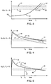
- Curve 65 is for a premium or higher quality fluid, i.e. a fluid formulated for extended service in defined test sequence
- curve 67 is for a standard or relatively lower quality fluid, i.e. a fluid formulated for standard service in the same test sequence.
- f M is on the order of 100 Hz. In general, f M is typically in the range of 1 Hz to 500 kHz.
- a fluid's real-impedance response 65, 67 rises relatively quickly, as a function of equipment use, to a maximum value (M M ) 69.
- the value of the peak 69 is not as critical to the useful life of the fluid as is the percent decrease from this peak value during fluid life.
- Curves 65 and 67 are scaled to have the same peak value 69.
- the real-impedance of both the premium and standard quality fluids decrease as a function of time, with the standard fluid decreasing more rapidly.
- threshold 71 When either fluid's real-impedance decreases below a threshold 71, the fluid condition has degraded to the point that the fluid should be changed soon, and when the real-impedance decreases below a second threshold 73, the fluid has reached the end of its useful life and should be changed now or as soon as operationally possible to protect the service life of the equipment.
- appropriate thresholds are set such that the ratios of the threshold-real-impedance to the fluid's peak-real-impedance are defined values independent of the quality of the fluid.
- the post-addition real-impedance 75 increases as a function of the volume-percent of the fluid addition, the peak real-impedance of the fluid added relative to the peak real impedance of the fluid already in the equipment, and the current condition of the fluid in the equipment.
- a fluid added later in a fluid's use cycle will generally increase the total fluid real-impedance more than an addition made early in a fluid's use cycle.
- a fluid addition to either a fluid with curve 65 or 67, extends the useful life of the total fluid in the equipment.
- FIG. 5 shows the imaginary impedance (Z im ) response 77, for a typical transportation or industrial fluid, to an applied low-frequency signal (f L ) with non-zero offset-voltage (V o ⁇ 0) at a fixed temperature as a function of equipment use since the last fluid change.
- the low frequency required for curve 77 is a function of apparatus electrode geometry, fluid temperature or temperature range and chemical composition of the fluid being monitored.
- f L is on the order of 1 Hz.
- f L is typically in the range of 10 mHz to 10 Hz.
- the required offset-voltage is primarily a function of the chemical composition of the fluid being monitored, and is, in general, in the range of 500 mV to 6 V.
- a fluid's imaginary impedance response 77 rises quickly, as a function of equipment use, to a maximum value (M L ) 79, after which the response decreases quickly at first, then less quickly, during fluid use.
- the value of the peak 79 is not as critical to the useful life of the fluid as is the percent decrease from this peak value during fluid life.
- a threshold 81 the fluid condition has degraded to the point that the fluid should be changed soon, and when the imaginary-impedance decreases below a second threshold 83 the fluid has reached the end of its useful life and should be changed now or as soon as operationally possible to protect the service life of the equipment.
- appropriate thresholds are set such that the ratios of the threshold-imaginary-impedance to the fluid's peak-imaginary-impedance are defined values independent of the quality of the fluid.
- the change in the low-frequency imaginary-impedance is a function of the volume-percent of the fluid addition, the peak imaginary-impedance of the fluid added relative to the peak imaginary-impedance of the fluid already in the equipment, and the current condition of the fluid in the equipment.
- the low-frequency imaginary-impedance shows a greater change when the fluid addition is made earlier in the fluid's use cycle.
- FIG. 5 further shows the effect of polar-coolant contamination, for example water, on a fluid's imaginary-impedance.
- polar-coolant contamination for example water
- fluids in applications where change in the fluid's high-frequency response is substantially less significant than the changes in the fluid's medium and low frequency responses that is, for fluids in those applications if Figures 3, 4, 5 were scaled to the same "use" axis, i.e. X-axis, only the very initial portion of FIG.
- Figures 3, 4, 5 show fluid response at fixed fluid temperature. Fluid response, however, at any of the frequencies is temperature dependent. For certain fluids in particular applications, variation in fluid response over an equipment's operating temperature range can be greater than the change in a fluid's response at fixed temperature between initial or peak values and the thresholds for "Change Fluid Soon" or "Change Fluid Now".
- the measurement apparatus must have means for controlling the fluid temperature, as apparatus 1 in FIG. 1 , or must have a means for measuring the fluid temperature, as apparatus 43 in FIG. 2 , so that a method of this invention can compensate or correct for changes in fluid temperature.
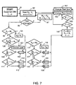
- FIG. 6 shows a first embodiment of a method of the present invention that uses a fluid's response to the above described high-, medium- and low-frequency signals to determine the quality and condition of a fluid in equipment where the fluid is maintained at constant temperature for condition determination.
- Constant temperature can be maintained either by the fluid measurement apparatus, for example apparatus 1 in FIG. 1 , or by the equipment or a means associated with the equipment in which the fluid is used.
- the method begins in block 91 each time the equipment is started, i.e. turned “on”.
- a variable "Y" is set equal to zero, and the method proceeds to block 93 to read fluid responses, S H , S M and S L , to high-, medium- and low-frequency signals respectively, which are obtained by a fluid measurement apparatus of the type described in association with FIG. 1 .
- S H , S M and S L can be dielectric, real-impedance and imaginary impedance responses respectively, as shown in Figures 3, 4, 5 respectively, or values that are essentially equivalent.
- analogue voltages, currents or digital inputs can be read that can be converted to appropriate fluid responses.
- ) at the medium frequency is essentially the same as the fluid's real-impedance (Z real ) due to a fluid's substantially smaller imaginary-impedance (Z im ); hence, for processing reasons total-impedance may be used.
- S H , S M and S L can be data collected by the apparatus over a short period of time with no filtering, or can be averaged over a longer period of time and filtered to minimize noise and to better quantify a fluid's response to the applied signals. In any case the method reads the data at fixed intervals of "X" seconds to determine fluid quality.
- the method determines if an essentially complete fluid change has been made since the last time the inputs were read. This determination can be based on an input to the method. For example, a maintenance person, or operator, could provide a signal when a fluid change is made that is communicated to the controller (e.g. by electrical conduit 27 to controller 17 of apparatus 1 in FIG. 1 ) and detected in block 95. As another example, a sensor or sensor system that detects fluid change either by fluid level changes or by other means could provide a signal that is detected in block 95. The determination of block 95 can also be made by a subroutine that uses inputs S H , S M and S L and no additional input to identify the fluid change.
- the values of the medium- and low-frequency response read in the previous fluid quality/condition determination, S MP , S LP , are set equal to S M , S L respectively since the previously stored values are not relevant in determining the fresh fluid's quality or condition.
- the thresholds for the high-frequency fluid determination L H1 , L H2 are set to "Hi" values (corresponding to thresholds 55, 57 respectively in FIG. 3 ) assuming that the fresh fluid is a premium quality fluid; an assumption that is tested later in the method.
- the method returns to block 93 where X seconds after the previous reading, S H , S M , S L are again read.
- block 95 determines if the determination in block 95 is "no"
- the method advances to block 99 which determines if the low-frequency response S L is greater than a stored maximum low-frequency response M L . If the answer is "yes”, which means that the low-frequency response has not reached its maximum value, than M L is replaced by S L in block 101 and no further analysis of the low-frequency response is done with the method advancing to block 103 where variable "L" is set equal to zero to indicate that the fluid condition, determined by the fluid's low-frequency response, is acceptable. If the answer to block 99 is "no", i.e. S L is no longer increasing, block 105 determines if the relative rate of decrease of S L is greater than a predetermined rate R L .
- the relative rate of low-frequency response change is the low-frequency response from the previous iteration of the method S LP minus the low frequency response of the current iteration S L , divided by the maximum value M L and by the time between the iterations, which, except for the first iteration after equipment start, equals X.
- the warning may be sent to memory for later retrieval, to a signaling device, for example a warning light, to alert an equipment operator, to a central maintenance facility to notify maintenance personnel, or a device to turn the equipment "off” to prevent equipment damage.
- the method in block 117 determines if the medium-frequency response S M is greater than a stored maximum medium-frequency response M M . If the answer is "yes”, which means that the medium-frequency response has not reached its maximum value, than M M is replaced by S M in block 119 and no further analysis of the medium-frequency response is done with the method advancing to block 121 where variable "M" is set equal to zero to indicate that the fluid condition determined by the fluid's medium-frequency response is acceptable. If the block 117 determination is "no", i.e. S M is no longer increasing, block 123 determines if the relative rate of decrease of S M is greater than a predetermined rate R M .
- the relative rate of medium frequency change is the medium-frequency response from the previous iteration of the method S MP minus the medium-frequency response of the current iteration S M , divided by the maximum value M M and by the time between the iterations, which, except for the first iteration after equipment start, equals X.
- the block 123 determination is "yes", that is the relative rate of S M decrease is greater than R M and this is not the first iteration after equipment start, there is high probability that the fluid is of a relatively low quality and in block 125 the thresholds for the high-frequency fluid determination L H1 , L H2 , which will be used until the next essentially complete fluid change, are set equal to "Lo" values (corresponding to thresholds 59, 61 respectively in FIG. 3 ).
- the method in block 135 determines whether the high-frequency response S H divided by I H , the initial high-frequency response when the fluid was fresh, is above a first threshold L H1 . If the determination is "no", the variable "H” is set equal to zero in block 137 to indicate that the fluid condition, determined by the high-frequency response, is acceptable. If the block 135 determination is "yes”, a determination is made in block 139 whether the high-frequency response S H divided by I H is above a second threshold L H2 .
- variable "F” equal to the sum of variables "H", "M” and “L”
- S MP medium- and low-frequencies response values
- the method returns to block 93 where X seconds after the previous reading, S H , S M , S L are again read and the method repeated. If the block 151 determination is "no”, then in block 153 the determination is made whether variable "F" equals 1. If the determination is "yes”, which means that the fluid condition determined by one of the high-, medium- and low-frequency responses was that the fluid should be changed soon, the method advances to block 155 where a "Change Fluid Soon" warning is sent.
- the warning may be sent to memory for later retrieval, to a signaling device, for example a warning light, that can alert an equipment operator, or to a central maintenance facility to notify maintenance personnel.
- a signaling device for example a warning light
- the method advances to block 157 where a "Change Fluid Now" warning is sent.
- the warning is sent to an appropriate location using an appropriate means, for example electrical conduit 27 of controller 17 of apparatus 1 in FIG. 1 .
- an appropriate means for example electrical conduit 27 of controller 17 of apparatus 1 in FIG. 1 .
- the method returns to block 93 where X seconds after the previous reading, S H , S M , S L are again read and the method repeated. The method continues to repeat until the equipment using the fluid is turned “off”.
- the method essentially continuously monitors the condition of a fluid and sends warnings when fluid condition exceeds thresholds. Also the method determines fluid quality to set the thresholds for the high-frequency fluid condition determination and monitors the relative rate of decrease of the low-frequency response to determine if a coolant may be leaking into the fluid.
- the embodiment of FIG. 6 has the fluid responses S H , S M , S L being read immediately after the equipment using the fluid is turned "on". While the embodiment is for monitoring fluids maintained at constant temperature, there may be applications/equipment where some equipment operation time is needed before the fluid reaches constant temperature. For such applications/equipment, an embodiment similar to that of FIG. 6 can include a step between blocks 93, 95 where after the equipment is turned “on” the method does not advance to block 95 until the fluid reaches a desired fluid temperature. Such a block will be shown in the embodiment of FIG. 9 .
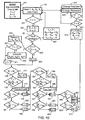
- FIG. 8 shows another embodiment of a method of the present invention for use in determining the quality and condition of a fluid in equipment where the fluid temperature is not maintained at constant temperature for fluid condition determination. This embodiment is appropriate for use in conjunction with apparatus 43 of FIG. 2 .
- the method in block 161 then reads fluid responses S H , S M and S L to applied high-, medium- and low-frequencies signals respectively, as previously discussed, and reads the fluid temperature T monitored by the measurement apparatus.
- the temperature T is used to convert fluid responses S H , S M , S L read at temperature T to constant temperature fluid responses S H ', S M ', S L ' such that the response variations due to temperature are effectively eliminated or minimized to an acceptable level.
- the response temperature conversions can be made using predetermined functions or look-up tables.
- the functions or tables can be permanently fixed in read-only memory, or the embodiment can allow the functions or tables to be updated, if needed, by appropriate means, for example by electrical conduit 27 to controller 17 of apparatus 43 in FIG. 2 , to allow for formulation changes of fluid being used in the equipment.
- the time interval X between reading the fluid responses is corrected to a constant temperature interval X' so that the rates of response change are properly corrected for temperature variations.
- the time interval conversion can be made using a predetermined function or a look-up table that is either permanently fixed in read-only memory or that can be updated if needed.
- the embodiment of FIG. 8 determines in block 95 if an essentially complete fluid change has been made since the last iteration and the remaining blocks numbered 167 to 227 are the same as the blocks numbered 97 to 157 of the embodiment of FIG. 6 except that the converted fluid responses S H ', S M ', S L ' and the converted time interval X' are used instead of the read responses S H , S M , S L and the fixed time interval X.
- the method essentially continuously monitors the condition of a fluid that varies in temperature. Also, as the fluid temperature varies, the method determines the fluid's quality in order to set the thresholds for the high-frequency fluid condition determination and monitors the relative rate of decrease of the low-frequency response to determine if a coolant may be leaking into the fluid.
- the embodiment of FIG. 8 determines fluid condition as the fluid varies for any temperature.
- the response and time interval conversion in block 163, however, is not an exact conversion due to the complex temperature-dependence of a fluid's electrical response. While high conversion accuracy over a wide temperature range is desired, conversion accuracy outside a fluid's typical operating temperature range is sometimes sacrificed to optimize accuracy within the range.
- an embodiment of the invention can include a step between blocks 159, 161 of FIG. 8 such that after the equipment is turned “on", that prevents the method from advancing to block 163 until the fluid reaches a predetermined temperature range.
- FIG. 9 shows another embodiment of a method of the present invention for determining the quality and condition of a fluid using high-, medium- and low-frequency responses in equipment where in addition to converting fluid responses above a fixed first temperature threshold for temperature variations, fluid responses at a second fixed fluid temperature are recorded for possible later or additional analysis of fluid quality and condition.
- This embodiment is appropriate for use in conjunction with equipment and sensing apparatus where a fluid is not always at constant temperature.
- temperature T1 to be above the highest ambient temperature experienced by the equipment so that after relatively long equipment "off” periods, the fluid temperature is below temperature T1 when the equipment is turned “on”. If the block 231 determination is "no", that is the fluid temperature is below preset temperature T1, then the method returns to block 161 and reads S H , S M , S L and T, X seconds after the previous reading and determines if the fluid temperature T is now at or above preset temperature T1 in block 231.
- the method continues reading the fluid responses and temperature every X seconds until the block 231 determination is "yes” and the method advances to block 163 where the fluid responses S H , S M and S L are converted to constant temperature fluid responses S H ', S M ', S L ' to eliminate or at least minimize to an acceptable level the effects of temperature variation on fluid responses. Also in block 233 the time interval X between reading fluid responses is corrected to a constant temperature interval X' so that the relative rates of response change are properly corrected for temperature variations. As discussed in the embodiment of FIG. 8 , the conversions can be made using functions or look-up tables that are either permanent or can be updated to allow for changes in formulation of the fluid being used in the equipment.
- the method determines if the fluid temperature T is equal to pre-selected fixed temperature T2 which, in this embodiment, is greater than or equal to T1. If the determination is "yes”, the method, in block 235, records the fluid responses S H , S M , S L and a time "t" that indicates when the data are recorded either in terms of calendar time or in terms of equipment use since the previous data were recorded.
- the unconverted, fixed-temperature data are recorded in memory for possible additional fluid analysis. Such fluid analysis may be done later when the memory is queried, for example, by a service technician using a service device that can communicate with the memory, to obtain a history of fluid response.
- Such additional fluid analysis may be done in conjunction with the present invention method to provide, for example, additional fluid condition or quality analysis.
- the collection of unconverted data at fixed temperature eliminates temperature variability and reduces the memory that would be needed if all data read every X seconds were recorded. After the data are recorded, or if the block 233 determination is "no", the method advances to block 95 where the method determines if an essentially complete fluid change has been made since the last iteration and blocks 167 to 227 are the same as the method embodiment described in FIG. 8 .
- FIG. 9 shows temperature T2 being greater than or equal to temperature T1
- an embodiment could be shown with blocks 233 and 235 of FIG. 9 placed between blocks 161 and 231 so that temperature T2 can be less than temperature T1.
- fluid response data recorded in block 235 at a lower temperature T2 may be used in a block, not shown, to determine if coolant is present before the fluid reaches temperature T1.
- FIG. 9 shows fluid response data being recorded for only one fixed temperature
- other embodiments can record data at multiple fixed temperatures for a more detailed fluid analysis.
- FIG. 10 shows another embodiment of a feature of the present invention for determining the quality and condition of a fluid in equipment where in addition to converting fluid responses above a fixed first temperature threshold to eliminate or minimize effects of temperature variations, the formulae or look-up tables used for the data conversions are updated each time the fluid temperature rises between two temperature thresholds with a rate that is greater than a preset value.
- variable T P is set equal to a fixed number T0, which will be described below.
- the method then in block 161 reads fluid responses S H , S M and S L and fluid temperature T.
- this embodiment in block 231 does not let the method advance to block 163 until the fluid temperature T equals or exceeds fixed temperature T1, which is a temperature above which temperature conversion of responses S H , S M and S L are known to be meaningfully accurate.
- the fluid responses and time interval X are converted to constant-temperature responses and time interval that are needed in the fluid quality and condition determination.
- the response conversions use formulae or look-up tables that the method has stored in memory.
- the method determines if an essentially complete fluid change has occurred to the equipment, and if a change has occurred, the method in block 167 initializes I H , M M , S MP , M L , S LP , L H1 and L H2 and returns to block 161 where fluid responses and temperature are again read X seconds after the previous reading. If the block 95 determination is that the fluid has not been changed then the method advances to block 243 where the determination is made if the rate of fluid temperature increase is greater than a fixed rate R T , and if "A" equals zero.
- the rate of fluid temperature increase is the previous iteration's temperature T P minus the current temperature T divided by the time interval between the two temperature readings which for iterations other than the first iteration after equipment start is "X".
- T0 in block 241 is chosen such that (T0-T1)/X is greater than R T so that T P in the first iteration will always result in a "yes" determination of block 243.
- the block 243 determination is "yes" in block 245 temperature T and the actual, non-converted, fluid responses are stored in a temporary memory array, which is cleared each time the equipment is turned “on”.
- the method determines if fluid temperature T is greater than or equal to a fixed temperature T3. Temperature T3 is selected such that fluid response data recorded in the temporary memory array between temperatures T1 and T3 allows a sufficiently accurate data-curve-fit over the temperature range from temperature T1 to the maximum temperature that the fluid may achieve in the equipment under any operating condition. If the block 247 determination is “yes” then in block 249 the data are curve-fit and new formulae or look-up tables substituted for the current formulae or look-up tables used to convert the fluid responses to constant temperature responses in block 163.
- T P is set equal to T in block 251 and the method determines fluid quality and condition in blocks 169 to 227 the same as the embodiments in Figures 8 and 9 .
- the method continues to record the fluid temperature and responses in block 245, and, if the fluid temperature T is greater than T3, to curve-fit the data and update conversion formulae or look-up tables, until the rate of fluid temperature increase is determined in block 243 to be less than R T .
- the block 253 determination is "no"
- "A" is set equal to 1 before advancing to step 169.
- fluid-response conversion formulae or look-up tables can only be updated once each time the equipment is turned “on”, and can only occur if the initial rate of fluid temperature increase is greater than or equal to rate R T between the temperatures T1 and T3.
- Rate R T and temperatures T1 and T3 are selected such that: 1) the conversion formulae or look-up tables are updated on a sufficiently regular interval, especially when an essentially complete fluid change occurs in the equipment; and 2) the updated conversions are sufficiently accurate for determining fluid quality and condition over the fluid's operating temperature range in the equipment.
- FIG. 10 allows for changes in the temperature dependent variations of fluid responses S H , S M and S L as the fluid ages during use and for changes of temperature dependencies when fluids of different formulation are added to the equipment.
- FIG. 11 shows another embodiment of a method of the present invention for determining the quality and condition of a fluid in equipment where in addition to converting fluid responses above a fixed first temperature threshold to eliminate or minimize effects of temperature variations, the formulae or look-up tables used for the data conversions can be updated each time a fluid change is made. Also the thresholds for determining the condition of the fluid can be updated each time a fluid change is made.
- the method determines if fluid temperature T is greater than or equal to a fixed temperature T1, and if the determination is "yes", the fluid responses S H , S M and S L are converted to constant temperature fluid responses S H ', S M ', S L ' and the time interval X between reading fluid responses is corrected to a constant temperature interval X'.
- the method determines if fluid has been essentially completely changed since the last method iteration.
- the determination of block 95 can be based on an input from a sensor or sensor system that detects fluid change by fluid level changes or other means, can be based on a subroutine that use S H , S M and S L , or S H ', S M ' and S L ', or on an external input from a maintenance person or operator.
- the determination is typically based on an input from a maintenance person or operator, because if the determination of block 95 is "yes", the method in block 255 reads fluid response conversion formulae or look-up tables S H (T), S M (T), S L (T) and thresholds L L1 , L L2 , L M1 , L M2 , L H1 , L H2 , which, if different than the fluid used previously, can be input by a maintenance person or operator using a means for inputting, for example a keypad of a remote input, and in block 257 the method 167 initializes I H , M M , S MP , M L , and S LP , and returns to block 161 where fluid responses and temperature are again read X seconds after the previous reading.
- block 95 determination is that the fluid has not been changed, than the method advances to blocks 169 to 227 where except for not having blocks 193, 195 the method is the same as the method embodiment described in FIG. 8 .
- the determination of block 193 and the setting of the high-frequency thresholds, L H1 , L H2 , in block 195 of the method of FIG. 8 are not needed since the appropriate high temperature thresholds for the fluid are read in block 255 of the embodiment in FIG. 11 .
- FIG. 11 allows for changes in fluid temperature response and condition thresholds when a fluid of different formulation is added to the equipment.
- FIG. 11 does not determine the quality of the fluid as in blocks 193 and set the high-frequency thresholds, L H1 , L H2 , as in blocks 167, 195 of the embodiment in FIG. 8
- an embodiment similar to that of FIG. 11 can read the high-frequency thresholds for a premium and a non-premium fluid, "Hi” and "Lo” respectively and have the high frequency thresholds set as in as in block 167, 193, 195 of FIG. 8 .
- FIG. 11 reads fluid response conversion formulae or look-up tables S H (T), S M (T), S L (T) and thresholds L L1 , L L2 , L M1 , L M2 , L H1 , L H2 , when the fluid is essentially completely changed, other embodiments need not read all of these inputs and may also read other inputs, for examples rates R L and R L when the fluid is changed.
- that determination can be based on an external input, for examples an input from a maintenance person or operator, or from a sensor or sensor system that detects fluid change by fluid level changes or other means, or the determination can be based on a subroutine the uses that uses S H , S M and S L , or S H ', S M ' and S L '.
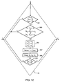
- Shown in FIG. 12 is a flow chart of a subroutine that can be used in block 95 of Figures 6 and 7 that uses fluid data to determine if the fluid has been essentially completely changed since the last time the equipment was "on".
- decision block 95 shown is a dashed outline of decision block 95 with input at the top and "yes” output on the right and “no” output on the left.
- Inputted into block 95 are the fluid responses S H , S M and S L that were read in block 93 of FIG. 6 and the values for the other variables used by the method.
- This subroutine assumes that an essentially complete fluid change only occurs when the equipment is "off” and fluid change need only be detected on the first iteration of the method after the equipment is turned “on”.
- a major change in the low-frequency response is define as the response S L read the first iteration after the equipment is turned “on” minus the response S LP , read the last iteration before the equipment was turned “off” being greater than a fixed value ⁇ L .
- a major change in the medium-frequency response is define as the absolute value of the response S M read the first iteration after the equipment is turned “on” minus the response S MP which was read the last iteration before the equipment was turned “off” being greater than a fixed value ⁇ M .
- a major change in the high-frequency response is define as the absolute value of the response S M read the first iteration after the equipment is turned “on” minus the response S MP which was read the last iteration before the equipment turned “off” being greater than a fixed value ⁇ M .
- the reason that the absolute value is not taken of the low-frequency data is because a major decrease in low-frequency response, with no major change in the other fluid responses is more likely be a coolant leak than a fluid change.
- the block 263 determination is "no"
- the subroutine exits block 95 with a "no” determination. If the block 263 determination is "yes”, i.e.
- the subroutine stores the current fluid responses S H , S M , S L in block 265 as S H1 , S M1 , S L1 respectively, pauses a fixed time "Z" in block 267 before reading new fluid responses S H , S M and S L in block 269.
- the subroutine determines in block 271 if the new S M , S L are greater than the stored previous values S M1 , S L1 respectively. If the fluid has had an essentially complete change, the low- and medium-frequency responses will be increasing.
- a "no" determination in block 271 causes the subroutine to exit block 95 with a "no” determination
- a "yes” determination in block 271 means the low- and medium-frequency responses are increasing as would be expected with an essentially complete fluid change, and causes the subroutine to exit block 95 with a "yes” determination, indicating that an essentially complete fluid change has occurred since the last time the equipment was "on".
- a similar subroutine could be used for block 95 in the embodiments in Figures 8 - 11 except that the subroutine would use constant temperature responses S H ', S M ' , S L ', in blocks 263, 265 and 271, and a block would be added between blocks 269 and 271 where the read fluid responses S H , S M , S L were converted to constant temperature results S H ', S M ', S L '.
- the invention is less vulnerable to reset errors that may occur if a service technician or operator must provide an input to the method.
- the method of the present invention allows for the determination of fluid quality and condition in an equipment where there are wide variations in the formulation of the fluid, which is shown in the following example.
- An apparatus which includes of a impedance/dielectric analyzer and a pair of parallel-disk electrodes each with surface area of about 3 cm 2 and separated by about 0.1 mm was used to determine the signal response of fluids of varying formulation tested in an industry standard Sequence IIIF test that rates oils for passenger car, gasoline engine application.
- the Sequence IIIF test is an about 85.5 hour oil test that uses a specially prepared Buick 3.8 L V-6 gasoline engine operated under determined conditions.
- oil samples are removed from the engine at about 10 hr intervals and at the end of the test, and the oil samples are tested using standard laboratory procedures for carbonyl and nitration increases (ASTM #839E), viscosity increase at about 40°C (ASTM D2270), TBN (ASTM D4739) and TAN (ASTM D664A). These laboratory procedures are used to determine the operating condition of the oil, such that when one or more of the procedure results exceeds a limit, the oil has reached the end of its useful life in the engine. If any oil sample is found to be at the end of its useful life, that oil has failed the Sequence IIIF test.
- the dielectric/impedance analyzer sequentially applied about 3 V peak-to-peak electrical signals to the electrodes immersed in the oil at about 1 Hz with an about 3 V offset such that the signal oscillated from about +1.5 V to about +4.5 V relative to ground, and at about 100 Hz and about 1 MHz with about zero volt offset set such that the signals oscillate from about -1.5 to about +1.5 V relative to ground.
- the dielectric/impedance analyzer determined the test oil's imaginary impedance (Z im ) at about 1 Hz, the test oil's real impedance (Z real ) at about 100 Hz and the test oil's dielectric ( ⁇ ) at about 1 MHz.
- Engine oil between the electrodes was maintained at about a constant 80°C temperature.
- the method of this invention was used to determine when to signal "Change Fluid Soon" and "Change Fluid Now” with an determination embodiment similar to that shown in FIG. 6 except that, since all fluids were tested to meet the same quality standard, the high frequency thresholds were held fixed, eliminating the need for blocks 123 and 125 and the need for resetting the high frequency thresholds in block 97 when the fluid was changed in the engine for the next fluid test.
- the rate for determining if there was a coolant leak, R L was 0.05/hr.
Landscapes
- Chemical & Material Sciences (AREA)
- Health & Medical Sciences (AREA)
- Engineering & Computer Science (AREA)
- Life Sciences & Earth Sciences (AREA)
- Medicinal Chemistry (AREA)
- Biochemistry (AREA)
- General Chemical & Material Sciences (AREA)
- Food Science & Technology (AREA)
- Chemical Kinetics & Catalysis (AREA)
- Physics & Mathematics (AREA)
- Analytical Chemistry (AREA)
- Oil, Petroleum & Natural Gas (AREA)
- General Health & Medical Sciences (AREA)
- General Physics & Mathematics (AREA)
- Immunology (AREA)
- Pathology (AREA)
- Investigating Or Analyzing Materials By The Use Of Electric Means (AREA)
- Testing And Monitoring For Control Systems (AREA)
Applications Claiming Priority (3)
| Application Number | Priority Date | Filing Date | Title |
|---|---|---|---|
| US271885 | 2002-10-16 | ||
| US10/271,885 US6861851B2 (en) | 2002-10-16 | 2002-10-16 | Method for on-line monitoring of quality and condition of non-aqueous fluids |
| PCT/US2003/032235 WO2004036210A1 (en) | 2002-10-16 | 2003-10-14 | Method for on-line monitoring of quality and condition of non-aqueous fluids |
Publications (2)
| Publication Number | Publication Date |
|---|---|
| EP1552292A1 EP1552292A1 (en) | 2005-07-13 |
| EP1552292B1 true EP1552292B1 (en) | 2008-09-17 |
Family
ID=32092543
Family Applications (1)
| Application Number | Title | Priority Date | Filing Date |
|---|---|---|---|
| EP03776310A Expired - Lifetime EP1552292B1 (en) | 2002-10-16 | 2003-10-14 | Method for on-line monitoring of quality and condition of non-aqueous fluids |
Country Status (10)
| Country | Link |
|---|---|
| US (1) | US6861851B2 (enExample) |
| EP (1) | EP1552292B1 (enExample) |
| JP (1) | JP4309350B2 (enExample) |
| KR (1) | KR101072208B1 (enExample) |
| AT (1) | ATE408821T1 (enExample) |
| AU (1) | AU2003284079B2 (enExample) |
| BR (1) | BR0315423A (enExample) |
| CA (1) | CA2502283A1 (enExample) |
| DE (1) | DE60323656D1 (enExample) |
| WO (1) | WO2004036210A1 (enExample) |
Families Citing this family (26)
| Publication number | Priority date | Publication date | Assignee | Title |
|---|---|---|---|---|
| US6984993B2 (en) * | 1999-04-28 | 2006-01-10 | Nexense Ltd. | Method and apparatus for making high-precision measurements |
| US20050114060A1 (en) * | 2003-11-03 | 2005-05-26 | The Lubrizol Corpration | On-line fluid monitoring that compensates for a fluid's temperature dependance |
| US6989680B2 (en) * | 2004-02-24 | 2006-01-24 | Eaton Corporation | Detection of coolant contamination in lubricating fluids |
| US6984986B2 (en) * | 2004-02-24 | 2006-01-10 | Eaton Corporation | Situ fluid condition monitoring |
| US7355415B2 (en) * | 2004-05-07 | 2008-04-08 | The Lubrizol Corporation | Method for on-line monitoring of condition of non-aqueous fluids |
| US20050248358A1 (en) * | 2004-05-07 | 2005-11-10 | The Lubrizol Corporation, A Corporation Of The State Of Ohio | Method for on-line monitoring of condition of non-aqueous fluids |
| IL166760A0 (en) * | 2004-05-13 | 2006-01-15 | Nexense Ltd | Method and apparatus for non-invasively monitoringconcentrations of glucose or other target substan ces |
| JP5158780B2 (ja) * | 2004-10-06 | 2013-03-06 | ザ ルブリゾル コーポレイション | スルホネートを含有する潤滑組成物 |
| US7362110B2 (en) * | 2005-04-06 | 2008-04-22 | Gm Global Technology Operations, Inc. | Measurement cell for liquids |
| US7259575B2 (en) * | 2005-04-08 | 2007-08-21 | The Lubrizol Corporation | Method for on-line fuel-dilution monitoring of engine lubricant |
| US20070202603A1 (en) * | 2006-02-27 | 2007-08-30 | Steven Wayne Counts | Apparatus and method for sampling and correcting fluids |
| DE102006027436A1 (de) * | 2006-06-12 | 2007-12-13 | Conti Temic Microelectronic Gmbh | Steuerung oder Regelung eines automatischen oder automatisierten Getriebes |
| US7739968B2 (en) * | 2006-07-25 | 2010-06-22 | General Vortex Energy, Inc. | System, apparatus and method for combustion of metals and other fuels |
| KR101730679B1 (ko) | 2009-11-25 | 2017-04-26 | 이데미쓰 고산 가부시키가이샤 | 윤활유의 열화·변질도 측정 방법 및 그의 측정 장치 |
| CN103954656A (zh) * | 2009-11-25 | 2014-07-30 | 出光兴产株式会社 | 润滑油的劣化度测定装置、以及机械、装置的润滑油监视系统 |
| KR101951399B1 (ko) * | 2010-11-22 | 2019-02-22 | 더루우브리졸코오포레이션 | 유체 상태를 모니터하는 방법 |
| JP6313908B2 (ja) | 2014-09-03 | 2018-04-18 | ゼブラ スキマーズ コーポレイションZebra Skimmers Corp. | 液体供給方法および液体供給システム |
| JP6174545B2 (ja) * | 2014-10-17 | 2017-08-02 | ファナック株式会社 | 臭気センサを用いた切削液の状態監視装置 |
| WO2016122667A1 (en) | 2015-01-30 | 2016-08-04 | Hewlett Packard Enterprise Development Lp | Sensors for cooling system fluid attributes |
| ES2530691B1 (es) * | 2015-02-02 | 2015-11-03 | Zertan, S.A. | Método de medida de la presencia de agua en filtros de gasóleo y sensor de agua para efectuar dicho método |
| JP6739223B2 (ja) * | 2016-04-27 | 2020-08-12 | Kyb株式会社 | センサ |
| US11016075B2 (en) * | 2017-07-20 | 2021-05-25 | Saudi Arabian Oil Company | Methods and systems for characterization of geochemical properties of hydrocarbons using microwaves |
| US11099168B2 (en) * | 2018-07-23 | 2021-08-24 | Schlumberger Technology Corporation | Methods and apparatus for water detection in multiphase flows |
| US11555813B2 (en) * | 2019-03-14 | 2023-01-17 | Bvba Dierickx-Tools | Apparatus and method for monitoring a condition of metalworking fluid of a metalworking fluid circuit of a metalworking machine |
| US11668668B2 (en) * | 2020-10-05 | 2023-06-06 | Pryor Knowledge Systems, Inc. | Mechanism for the real-time prediction of incipient failure in working fluids |
| US20250180514A1 (en) * | 2023-11-30 | 2025-06-05 | Wisconsin Alumni Research Foundation | Non-Invasive Multiparameter Sensor |
Family Cites Families (20)
| Publication number | Priority date | Publication date | Assignee | Title |
|---|---|---|---|---|
| ES2086534T3 (es) | 1990-01-05 | 1996-07-01 | Lubrizol Corp | Fluido de transmision universal. |
| EP0531585B1 (en) | 1991-09-09 | 1998-11-04 | Ethyl Petroleum Additives Limited | Oil additive concentrates and lubricants of enhanced performance capabilities |
| US5331287A (en) | 1992-07-31 | 1994-07-19 | Hughes Aircraft Company | Device and method for sensing water and/or acid in the presence of water in non-aqueous media |
| JPH0682408A (ja) | 1992-09-03 | 1994-03-22 | Tokyo Gas Co Ltd | オイルの劣化度評価方法,およびその評価装置 |
| US5518590A (en) | 1994-06-21 | 1996-05-21 | Pennzoil Products Company | Electrochemical sensors for motor oils and other lubricants |
| US5540086A (en) | 1994-08-30 | 1996-07-30 | Kavlico Corporation | Oil deterioration sensor |
| US5656767A (en) | 1996-03-08 | 1997-08-12 | Computational Systems, Inc. | Automatic determination of moisture content and lubricant type |
| US5933016A (en) | 1996-08-30 | 1999-08-03 | The University Of Dayton | Single electrode conductivity technique |
| US5889200A (en) | 1996-08-30 | 1999-03-30 | The University Of Dayton | Tandem technique for fluid monitoring |
| US5824889A (en) | 1997-03-06 | 1998-10-20 | Kavlico Corporation | Capacitive oil deterioration and contamination sensor |
| US6028433A (en) | 1997-05-14 | 2000-02-22 | Reid Asset Management Company | Portable fluid screening device and method |
| US6278281B1 (en) | 1998-12-23 | 2001-08-21 | Eaton Corporation | Fluid condition monitor |
| US6217745B1 (en) | 1999-08-24 | 2001-04-17 | Pennzoil-Quaker State | Method for monitoring agents in hydrocarbon fluids |
| US6268737B1 (en) * | 1999-10-07 | 2001-07-31 | Detroit Diesel Corporation | Method and system for determining oil quality |
| US6380746B1 (en) * | 1999-11-03 | 2002-04-30 | Eaton Corporation | Monitoring fluid condition with a spiral electrode configuration |
| US6377052B1 (en) * | 1999-11-03 | 2002-04-23 | Eaton Corporation | Monitoring fluid condition through an aperture |
| US6535001B1 (en) | 2000-05-01 | 2003-03-18 | Delphi Technologies, Inc | Method and device for sensing oil condition |
| US6443006B1 (en) * | 2000-05-09 | 2002-09-03 | Engineered Machined Products, Inc. | Device which measures oil level and dielectric strength with a capacitance based sensor using a ratiometric algorithm |
| US6577112B2 (en) * | 2001-03-09 | 2003-06-10 | The Lubrizol Corporation | Method and apparatus for on-line monitoring of quality and/or condition of highly resistive fluids |
| US7043402B2 (en) | 2001-12-20 | 2006-05-09 | The Precision Instrument Corp. | On-line oil condition sensor system for rotating and reciprocating machinery |
-
2002
- 2002-10-16 US US10/271,885 patent/US6861851B2/en not_active Expired - Lifetime
-
2003
- 2003-10-14 DE DE60323656T patent/DE60323656D1/de not_active Expired - Lifetime
- 2003-10-14 AU AU2003284079A patent/AU2003284079B2/en not_active Ceased
- 2003-10-14 WO PCT/US2003/032235 patent/WO2004036210A1/en not_active Ceased
- 2003-10-14 BR BR0315423-8A patent/BR0315423A/pt not_active IP Right Cessation
- 2003-10-14 EP EP03776310A patent/EP1552292B1/en not_active Expired - Lifetime
- 2003-10-14 AT AT03776310T patent/ATE408821T1/de not_active IP Right Cessation
- 2003-10-14 CA CA002502283A patent/CA2502283A1/en not_active Abandoned
- 2003-10-14 KR KR1020057006659A patent/KR101072208B1/ko not_active Expired - Fee Related
- 2003-10-14 JP JP2004544845A patent/JP4309350B2/ja not_active Expired - Fee Related
Also Published As
| Publication number | Publication date |
|---|---|
| AU2003284079A1 (en) | 2004-05-04 |
| KR101072208B1 (ko) | 2011-10-10 |
| KR20050056249A (ko) | 2005-06-14 |
| ATE408821T1 (de) | 2008-10-15 |
| US6861851B2 (en) | 2005-03-01 |
| AU2003284079B2 (en) | 2008-11-20 |
| EP1552292A1 (en) | 2005-07-13 |
| WO2004036210A1 (en) | 2004-04-29 |
| CA2502283A1 (en) | 2004-04-29 |
| US20040075448A1 (en) | 2004-04-22 |
| DE60323656D1 (de) | 2008-10-30 |
| BR0315423A (pt) | 2005-08-23 |
| JP2006503289A (ja) | 2006-01-26 |
| JP4309350B2 (ja) | 2009-08-05 |
Similar Documents
| Publication | Publication Date | Title |
|---|---|---|
| EP1552292B1 (en) | Method for on-line monitoring of quality and condition of non-aqueous fluids | |
| AU2002247205B2 (en) | Method and apparatus for on-line monitoring of quality and/or condition of highly resistive fluids | |
| WO2008030912A2 (en) | Method for on-line monitoring of condition of non-aqueous fluids | |
| AU2002247205A1 (en) | Method and apparatus for on-line monitoring of quality and/or condition of highly resistive fluids | |
| US7292048B2 (en) | Method and apparatus for measuring a dielectric response of an electrical insulating system | |
| US7259575B2 (en) | Method for on-line fuel-dilution monitoring of engine lubricant | |
| EP1743167B1 (en) | Method for on-line monitoring of condition of non-aqueous fluids | |
| WO2009015090A1 (en) | Method and apparatus for measuring properties of weak electrolytic, organic fluids such as hydrocarbon-based fluids | |
| US20050114060A1 (en) | On-line fluid monitoring that compensates for a fluid's temperature dependance | |
| US20240393276A1 (en) | Sensor device |
Legal Events
| Date | Code | Title | Description |
|---|---|---|---|
| PUAI | Public reference made under article 153(3) epc to a published international application that has entered the european phase |
Free format text: ORIGINAL CODE: 0009012 |
|
| 17P | Request for examination filed |
Effective date: 20050414 |
|
| AK | Designated contracting states |
Kind code of ref document: A1 Designated state(s): AT BE BG CH CY CZ DE DK EE ES FI FR GB GR HU IE IT LI LU MC NL PT RO SE SI SK TR |
|
| AX | Request for extension of the european patent |
Extension state: AL LT LV MK |
|
| DAX | Request for extension of the european patent (deleted) | ||
| 17Q | First examination report despatched |
Effective date: 20060802 |
|
| GRAP | Despatch of communication of intention to grant a patent |
Free format text: ORIGINAL CODE: EPIDOSNIGR1 |
|
| GRAS | Grant fee paid |
Free format text: ORIGINAL CODE: EPIDOSNIGR3 |
|
| GRAA | (expected) grant |
Free format text: ORIGINAL CODE: 0009210 |
|
| AK | Designated contracting states |
Kind code of ref document: B1 Designated state(s): AT BE BG CH CY CZ DE DK EE ES FI FR GB GR HU IE IT LI LU MC NL PT RO SE SI SK TR |
|
| REG | Reference to a national code |
Ref country code: GB Ref legal event code: FG4D |
|
| REG | Reference to a national code |
Ref country code: CH Ref legal event code: EP |
|
| REG | Reference to a national code |
Ref country code: IE Ref legal event code: FG4D |
|
| REF | Corresponds to: |
Ref document number: 60323656 Country of ref document: DE Date of ref document: 20081030 Kind code of ref document: P |
|
| REG | Reference to a national code |
Ref country code: SE Ref legal event code: TRGR |
|
| PG25 | Lapsed in a contracting state [announced via postgrant information from national office to epo] |
Ref country code: SI Free format text: LAPSE BECAUSE OF FAILURE TO SUBMIT A TRANSLATION OF THE DESCRIPTION OR TO PAY THE FEE WITHIN THE PRESCRIBED TIME-LIMIT Effective date: 20080917 Ref country code: FI Free format text: LAPSE BECAUSE OF FAILURE TO SUBMIT A TRANSLATION OF THE DESCRIPTION OR TO PAY THE FEE WITHIN THE PRESCRIBED TIME-LIMIT Effective date: 20080917 Ref country code: AT Free format text: LAPSE BECAUSE OF FAILURE TO SUBMIT A TRANSLATION OF THE DESCRIPTION OR TO PAY THE FEE WITHIN THE PRESCRIBED TIME-LIMIT Effective date: 20080917 |
|
| NLV1 | Nl: lapsed or annulled due to failure to fulfill the requirements of art. 29p and 29m of the patents act | ||
| PG25 | Lapsed in a contracting state [announced via postgrant information from national office to epo] |
Ref country code: BE Free format text: LAPSE BECAUSE OF FAILURE TO SUBMIT A TRANSLATION OF THE DESCRIPTION OR TO PAY THE FEE WITHIN THE PRESCRIBED TIME-LIMIT Effective date: 20080917 |
|
| PG25 | Lapsed in a contracting state [announced via postgrant information from national office to epo] |
Ref country code: ES Free format text: LAPSE BECAUSE OF FAILURE TO SUBMIT A TRANSLATION OF THE DESCRIPTION OR TO PAY THE FEE WITHIN THE PRESCRIBED TIME-LIMIT Effective date: 20081228 Ref country code: BG Free format text: LAPSE BECAUSE OF FAILURE TO SUBMIT A TRANSLATION OF THE DESCRIPTION OR TO PAY THE FEE WITHIN THE PRESCRIBED TIME-LIMIT Effective date: 20081217 |
|
| PG25 | Lapsed in a contracting state [announced via postgrant information from national office to epo] |
Ref country code: NL Free format text: LAPSE BECAUSE OF FAILURE TO SUBMIT A TRANSLATION OF THE DESCRIPTION OR TO PAY THE FEE WITHIN THE PRESCRIBED TIME-LIMIT Effective date: 20080917 Ref country code: RO Free format text: LAPSE BECAUSE OF FAILURE TO SUBMIT A TRANSLATION OF THE DESCRIPTION OR TO PAY THE FEE WITHIN THE PRESCRIBED TIME-LIMIT Effective date: 20080917 Ref country code: PT Free format text: LAPSE BECAUSE OF FAILURE TO SUBMIT A TRANSLATION OF THE DESCRIPTION OR TO PAY THE FEE WITHIN THE PRESCRIBED TIME-LIMIT Effective date: 20090217 Ref country code: MC Free format text: LAPSE BECAUSE OF NON-PAYMENT OF DUE FEES Effective date: 20081031 Ref country code: SK Free format text: LAPSE BECAUSE OF FAILURE TO SUBMIT A TRANSLATION OF THE DESCRIPTION OR TO PAY THE FEE WITHIN THE PRESCRIBED TIME-LIMIT Effective date: 20080917 Ref country code: CZ Free format text: LAPSE BECAUSE OF FAILURE TO SUBMIT A TRANSLATION OF THE DESCRIPTION OR TO PAY THE FEE WITHIN THE PRESCRIBED TIME-LIMIT Effective date: 20080917 |
|
| REG | Reference to a national code |
Ref country code: CH Ref legal event code: PL |
|
| REG | Reference to a national code |
Ref country code: IE Ref legal event code: MM4A |
|
| PLBE | No opposition filed within time limit |
Free format text: ORIGINAL CODE: 0009261 |
|
| STAA | Information on the status of an ep patent application or granted ep patent |
Free format text: STATUS: NO OPPOSITION FILED WITHIN TIME LIMIT |
|
| PG25 | Lapsed in a contracting state [announced via postgrant information from national office to epo] |
Ref country code: EE Free format text: LAPSE BECAUSE OF FAILURE TO SUBMIT A TRANSLATION OF THE DESCRIPTION OR TO PAY THE FEE WITHIN THE PRESCRIBED TIME-LIMIT Effective date: 20080917 Ref country code: DK Free format text: LAPSE BECAUSE OF FAILURE TO SUBMIT A TRANSLATION OF THE DESCRIPTION OR TO PAY THE FEE WITHIN THE PRESCRIBED TIME-LIMIT Effective date: 20080917 |
|
| 26N | No opposition filed |
Effective date: 20090618 |
|
| PG25 | Lapsed in a contracting state [announced via postgrant information from national office to epo] |
Ref country code: LI Free format text: LAPSE BECAUSE OF NON-PAYMENT OF DUE FEES Effective date: 20081031 Ref country code: IE Free format text: LAPSE BECAUSE OF NON-PAYMENT OF DUE FEES Effective date: 20081014 Ref country code: CH Free format text: LAPSE BECAUSE OF NON-PAYMENT OF DUE FEES Effective date: 20081031 |
|
| PG25 | Lapsed in a contracting state [announced via postgrant information from national office to epo] |
Ref country code: HU Free format text: LAPSE BECAUSE OF FAILURE TO SUBMIT A TRANSLATION OF THE DESCRIPTION OR TO PAY THE FEE WITHIN THE PRESCRIBED TIME-LIMIT Effective date: 20090318 Ref country code: LU Free format text: LAPSE BECAUSE OF NON-PAYMENT OF DUE FEES Effective date: 20081014 Ref country code: CY Free format text: LAPSE BECAUSE OF FAILURE TO SUBMIT A TRANSLATION OF THE DESCRIPTION OR TO PAY THE FEE WITHIN THE PRESCRIBED TIME-LIMIT Effective date: 20080917 |
|
| PG25 | Lapsed in a contracting state [announced via postgrant information from national office to epo] |
Ref country code: TR Free format text: LAPSE BECAUSE OF FAILURE TO SUBMIT A TRANSLATION OF THE DESCRIPTION OR TO PAY THE FEE WITHIN THE PRESCRIBED TIME-LIMIT Effective date: 20080917 |
|
| PG25 | Lapsed in a contracting state [announced via postgrant information from national office to epo] |
Ref country code: GR Free format text: LAPSE BECAUSE OF FAILURE TO SUBMIT A TRANSLATION OF THE DESCRIPTION OR TO PAY THE FEE WITHIN THE PRESCRIBED TIME-LIMIT Effective date: 20081218 |
|
| REG | Reference to a national code |
Ref country code: FR Ref legal event code: PLFP Year of fee payment: 13 |
|
| REG | Reference to a national code |
Ref country code: FR Ref legal event code: PLFP Year of fee payment: 14 |
|
| REG | Reference to a national code |
Ref country code: FR Ref legal event code: PLFP Year of fee payment: 15 |
|
| PGFP | Annual fee paid to national office [announced via postgrant information from national office to epo] |
Ref country code: IT Payment date: 20171024 Year of fee payment: 15 |
|
| REG | Reference to a national code |
Ref country code: FR Ref legal event code: PLFP Year of fee payment: 16 |
|
| PG25 | Lapsed in a contracting state [announced via postgrant information from national office to epo] |
Ref country code: IT Free format text: LAPSE BECAUSE OF NON-PAYMENT OF DUE FEES Effective date: 20181014 |
|
| PGFP | Annual fee paid to national office [announced via postgrant information from national office to epo] |
Ref country code: FR Payment date: 20191025 Year of fee payment: 17 |
|
| PGFP | Annual fee paid to national office [announced via postgrant information from national office to epo] |
Ref country code: DE Payment date: 20201028 Year of fee payment: 18 Ref country code: SE Payment date: 20201028 Year of fee payment: 18 Ref country code: GB Payment date: 20201027 Year of fee payment: 18 |
|
| PG25 | Lapsed in a contracting state [announced via postgrant information from national office to epo] |
Ref country code: FR Free format text: LAPSE BECAUSE OF NON-PAYMENT OF DUE FEES Effective date: 20201031 |
|
| REG | Reference to a national code |
Ref country code: DE Ref legal event code: R119 Ref document number: 60323656 Country of ref document: DE |
|
| REG | Reference to a national code |
Ref country code: SE Ref legal event code: EUG |
|
| GBPC | Gb: european patent ceased through non-payment of renewal fee |
Effective date: 20211014 |
|
| PG25 | Lapsed in a contracting state [announced via postgrant information from national office to epo] |
Ref country code: SE Free format text: LAPSE BECAUSE OF NON-PAYMENT OF DUE FEES Effective date: 20211015 Ref country code: GB Free format text: LAPSE BECAUSE OF NON-PAYMENT OF DUE FEES Effective date: 20211014 Ref country code: DE Free format text: LAPSE BECAUSE OF NON-PAYMENT OF DUE FEES Effective date: 20220503 |
|
| P01 | Opt-out of the competence of the unified patent court (upc) registered |
Effective date: 20230426 |
|
| P02 | Opt-out of the competence of the unified patent court (upc) changed |
Effective date: 20230625 |