EP1552101B1 - Improvements in and relating to glazing clips for ancillary elements on glazing units - Google Patents
Improvements in and relating to glazing clips for ancillary elements on glazing units Download PDFInfo
- Publication number
- EP1552101B1 EP1552101B1 EP03771183.5A EP03771183A EP1552101B1 EP 1552101 B1 EP1552101 B1 EP 1552101B1 EP 03771183 A EP03771183 A EP 03771183A EP 1552101 B1 EP1552101 B1 EP 1552101B1
- Authority
- EP
- European Patent Office
- Prior art keywords
- glazing
- kit
- interengaging
- ancillary
- cross
- Prior art date
- Legal status (The legal status is an assumption and is not a legal conclusion. Google has not performed a legal analysis and makes no representation as to the accuracy of the status listed.)
- Expired - Lifetime
Links
Images


Classifications
-
- E—FIXED CONSTRUCTIONS
- E06—DOORS, WINDOWS, SHUTTERS, OR ROLLER BLINDS IN GENERAL; LADDERS
- E06B—FIXED OR MOVABLE CLOSURES FOR OPENINGS IN BUILDINGS, VEHICLES, FENCES OR LIKE ENCLOSURES IN GENERAL, e.g. DOORS, WINDOWS, BLINDS, GATES
- E06B3/00—Window sashes, door leaves, or like elements for closing wall or like openings; Layout of fixed or moving closures, e.g. windows in wall or like openings; Features of rigidly-mounted outer frames relating to the mounting of wing frames
- E06B3/68—Window bars
- E06B3/685—False glazing bars
Definitions
- the present invention relates to glazing clips, glazing assemblies, kits for the construction of ancillary elements on a glazing unit and to methods of construction of glazing assemblies.
- a typical glazing assembly comprises a sealed double glazed unit about the edge of which is provided a foursided frame.
- the sealed glazing unit comprises a first glazing panel, typically of glass, in a spaced, parallel, face to face relationship with a similar second glazing panel.
- a beading is provided, typically a poly vinyl chloride (PVC) material to maintain the spaced apart relationship and to prevent the ingress of water between the panels.
- the frame is typically a PVC moulding with PVC nitrile gaskets for receiving the glazing unit.
- a first side of a glazing unit is intended to be an interior panel and a second side as exterior panel, in use.
- a Georgian bar is a cross or trellis effect on the glazing assembly giving the appearance that the glazing is made up of multiple smaller glazing panels in a plane.
- US 2 854 709 discloses a glazing clip extending around opposed face of a sheet of glass and including an integral anchoring leg with points intended to bite into a peripheral frame.
- US 2 723 427 discloses a glazing clip extending around opposed faces of a glazing panel with legs to provide engagement with a glazing compound at the periphery of the panel.
- US 2 637 423 discloses a glazing clip extending over one side only of a sheet of class, to engage with a sash bar of a special design to press and hold a glass sheet in position at the periphery of the glazing.
- GB 659, 839 discloses a glazing clip having a channelled part for receiving the peripheral edge of a sheet of glass.
- GB 2 010 948 discloses a glazing clip for receiving the peripheral edge of a sheet of glass and is of a general U shape extending over opposed faces of the pane.
- US 2 934 180 discloses a batten strip for interconnecting structural elements, the strip being U or H shaped and extending over the periphery of the structural elements.
- EP-A-0152813 discloses a kit for incorporating a Georgianeffect bar on a window, the kit of comprising for one edge of a glazing panel, pair of end-engaging elements each end-engaging element receiving an extruded plate from which extends an upstanding portion onto which a Georgian bar effect cover is applied.
- a glazing clip 2 having a generally U-shaped body 4 from which extend means for interengaging with an ancillary element.
- the means for interengaging with an ancillary element comprise a first interengaging member 6 and a second interengaging member 8.
- the generally U-shaped body 4 comprises a base 10 from which extend two substantially similar arms 12, 14 towards the distal end of which the first and second interengaging members 6, 8 lie.
- the arms 12, 14 of the U-shaped body 4 are inclined slightly from perpendicular with the base 10. That is the gap between the distal end of the arms 12, 14 is less than the distance between the other end of the arms 12, 14 at the base end.
- Each interengaging member 6, 8 comprises an upstanding portion extending from the corresponding arm 12, 14, which upstanding portion comprises a male member (for interengagement with a female member as described below), which has a plurality of rebated portions therefore.
- the first and second interengaging members extend for just over half the length of the arms 12, 14 from the distal end thereof.
- the glazing clip is formed from a rigid thermoplastic material by injection moulding.
- the cross-piece 20 comprises a planar base 22 upstanding from which is a first interengaging member 24, a second interengaging member 26 and a third interengaging member 28.
- the base 22 is generally an elongate rectangle across the width of which extends first interengaging member 24.
- second and third interengaging members 26, 28 are second and third interengaging members 26, 28.
- Corresponding gaps 30, 32 are provided between first and second and first and third interengaging members.
- Interengaging members 24, 26, 28 are substantially similar to the interengaging members 6, 8 of glazing clip 2.
- kit of parts comprising four substantially similar glazing clips 2, two cross pieces 20 and two lots of three ancillary elements 40, 42, 44 cut to length. It is noted that an ancillary element may be provided as a single piece and cut to suitable lengths on site.
- a known ancillary element 40 is shown in Figure 7 for producing a Georgian bar effect.
- Each ancillary element is of a substantially similar cross-section.
- the ancillary element 40 comprises a generally n-shaped Georgian bar cover 46 with co-extruded gaskets 48, 50 extending from the depending arms thereof.
- In the interior (in use) of the ancillary element 40 there is a female part of an interengaging member 52 suitable for interengaging with any of the interengaging members of the glazing clip 2 or cross-piece 20.
- the ancillary element 40 has a lower face 53 intended, in use, to lie against or over a glazing panel, as described below.
- the width of body 4 of glazing clip 2 is no more than the width of the ancillary element so the latter substantially hides the former in use.
- a glazing unit 60 is a double glazing unit of known type with interior (ie between the two glazing panels) cross members, an internal Georgian bar 62.
- the interior cross members are a known optional but desirable feature to enhance the final appearance of the product.
- glazing clips 2 are fitted to each edge of the glazing unit 60 to suit the position of the internal Georgian bar 62.
- the slight incline of the arms 12, 14 of the glazing clips 2 means that once the four clips 2 have been slid over the edge of glazing unit 60 they hold themselves in place.
- first interengaging member 6 is on one side of the glazing unit and second interengaging member 8 is on the other side of the glazing unit.
- the glazing clips 2 are fitted around the sealed glazing unit 60 to suit the position of the spacer bar.
- the glazing unit 60 is installed into a known frame 64 in the normal manner. It is recommended that it is checked that the clips 2 are in the right position before final beading of the assembly is carried out.
- the frame 64 incorporates gasket elements (not shown) for receiving the glazing unit 60 therein, which gaskets provide sufficient leeway for the relatively thin (typically, the wall size is 1mm) glazing clips 2 to extend across the edge of the glazing unit 60 without interfering with the fitting of the glazing unit 60 in the frame 64.
- the shortest full span ancillary element 40 which will be one of the final external Georgian bar elements, is cut (if required) and mitred (if required) to the length required for fitting into the frame 64.
- the cross-piece 20 is fitted with first interengaging member in the female interengaging member 52 thereof.
- the cross-piece 20 is located centrally on the ancillary element 40.
- the ancillary element 40 is then push fitted as a snap-fit on to the exposed interengaging members 6 of the glazing clips 2.
- ancillary elements 42 and 44 are, if necessary, cut to length and mitred.
- Ancillary elements 42, 44 are then push fitted on to interengaging members 6 (of glazing clips 2) and the second and third interengaging members 26, 28 of the cross-piece.
- the lower face 53 therefore lies against the glazing panel 60.
- the interengaging member 6 thus interengages with the ancillary element 42 in the lower face 53 thereof by a snap fit connection.
- a longitudinal slot 55 is provided to receive interengaging means 6.
- one side of the glazing unit has the appearance of a Georgian bar with a single cross.
- a small double sided tape patch (not shown) may be applied at each cross piece between the cross piece and the glazing panel, or alternatively a thin bead of translucent silicone (not shown) may be used. This helps secure the cross piece in the long term and reduces the risk of rattling.
- a single glazing clip can provide interengaging members on one or both sides of a glazing unit.
- the interengaging members are inherently aligned and do not interfere with the frame because of the thin body of the clip. A pleasing Georgian effect window assembly can, therefore, be provided.
- the present invention is suitable for glazing units having any number of glazing panels from one upwards, requiring only an adjustment of the length of the base. It will also be appreciated that the order of the method of construction described above can be altered somewhat if desired.
Description
- The present invention relates to glazing clips, glazing assemblies, kits for the construction of ancillary elements on a glazing unit and to methods of construction of glazing assemblies.
- A typical glazing assembly comprises a sealed double glazed unit about the edge of which is provided a foursided frame. The sealed glazing unit comprises a first glazing panel, typically of glass, in a spaced, parallel, face to face relationship with a similar second glazing panel. At the peripheral edge of the glazing panels and about their edges, a beading is provided, typically a poly vinyl chloride (PVC) material to maintain the spaced apart relationship and to prevent the ingress of water between the panels. The frame is typically a PVC moulding with PVC nitrile gaskets for receiving the glazing unit. A first side of a glazing unit is intended to be an interior panel and a second side as exterior panel, in use.
- Some customers desire an effect on their windows such as the appearance of a Georgian bar thereon. A Georgian bar is a cross or trellis effect on the glazing assembly giving the appearance that the glazing is made up of multiple smaller glazing panels in a plane.
- For reasons of manufacturing complexity, it is undesireable to manufacture genuine Georgian windows, but the appearance is often sought.
-
US 2 854 709 discloses a glazing clip extending around opposed face of a sheet of glass and including an integral anchoring leg with points intended to bite into a peripheral frame. -
US 2 723 427 discloses a glazing clip extending around opposed faces of a glazing panel with legs to provide engagement with a glazing compound at the periphery of the panel. -
US 2 637 423 discloses a glazing clip extending over one side only of a sheet of class, to engage with a sash bar of a special design to press and hold a glass sheet in position at the periphery of the glazing. -
GB 659, 839 -
GB 2 010 948 -
US 2 934 180 discloses a batten strip for interconnecting structural elements, the strip being U or H shaped and extending over the periphery of the structural elements. -
EP-A-0152813 discloses a kit for incorporating a Georgianeffect bar on a window, the kit of comprising for one edge of a glazing panel, pair of end-engaging elements each end-engaging element receiving an extruded plate from which extends an upstanding portion onto which a Georgian bar effect cover is applied. - It is an aim of preferred embodiments of the present invention to obviate or overcome a problem associated with the prior art, whether referred to herein or otherwise.
- According to the present invention in a first aspect, there is provided a kit according to
claim 1. - Further features of the present invention are set out in the appended claims.
- The present invention will now be described by way of example only, with reference to the drawings that follow; in which:
-
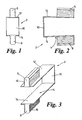
Figure 1 is a front view of a glazing clip according to the present invention. -
Figure 2 is a side view of the glazing clip shown inFigure 1 . -
Figure 3 is a perspective view of the glazing clip shown inFigures 1 and 2 . -
Figure 4 is a front view of a cross-piece for use with the present invention. -
Figure 5 is a side view of the cross-piece shown inFigure 4 . -
Figure 6 is a perspective view of a kit according to the present invention. -
Figure 7 is a cross-sectional elevation of an ancillary element for use with the present invention. -
Figure 8 is a perspective view of a first stage in a method of construction according to the present invention. -
Figure 9 is a perspective view of a second stage in a method of construction according to the present invention. -
Figure 10 is a perspective view of a third stage in a method of construction according to the present invention. -
Figure 11 is a perspective view of a fourth stage in a method of construction according to the present invention. -
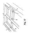
Figure 12 is a perspective view of a fifth stage in a method of construction according to the present invention. -
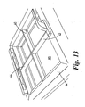
Figure 13 is a perspective view of a sixth stage in a method of construction according to the present invention. - Referring to
Figures 1-3 of the drawings that follow, there is shown aglazing clip 2 having a generally U-shaped body 4 from which extend means for interengaging with an ancillary element. The means for interengaging with an ancillary element comprise a first interengagingmember 6 and a second interengagingmember 8. - The generally U-shaped body 4 comprises a
base 10 from which extend two substantiallysimilar arms members - As shown most clearly in
Figure 2 of the drawings, thearms base 10. That is the gap between the distal end of thearms arms - Each
interengaging member corresponding arm arms - The glazing clip is formed from a rigid thermoplastic material by injection moulding.
- Referring to
Figures 4 and 5 of the drawings that follow, there is shown across-piece 20. Thecross-piece 20 comprises aplanar base 22 upstanding from which is a first interengagingmember 24, a second interengagingmember 26 and a third interengagingmember 28. Thebase 22 is generally an elongate rectangle across the width of which extends firstinterengaging member 24. Generally perpendicular to the first interengagingmember 24 and running parallel to the length ofbase 22 are second and third interengagingmembers gaps members members glazing clip 2. - Referring to
Figure 6 of the drawings that follow, there is shown a kit of parts according to the present invention, the kit comprising four substantiallysimilar glazing clips 2, twocross pieces 20 and two lots of threeancillary elements - A known
ancillary element 40 is shown inFigure 7 for producing a Georgian bar effect. Each ancillary element is of a substantially similar cross-section. Theancillary element 40 comprises a generally n-shapedGeorgian bar cover 46 withco-extruded gaskets ancillary element 40 there is a female part of aninterengaging member 52 suitable for interengaging with any of the interengaging members of theglazing clip 2 orcross-piece 20. Theancillary element 40 has alower face 53 intended, in use, to lie against or over a glazing panel, as described below. The width of body 4 ofglazing clip 2 is no more than the width of the ancillary element so the latter substantially hides the former in use. - A method of usage of the preferred embodiment of the present invention will now be described with reference to
Figures 8-13 of the drawings that follow. - Referring to
Figure 8 of the drawings that follow, aglazing unit 60 is a double glazing unit of known type with interior (ie between the two glazing panels) cross members, an internalGeorgian bar 62. The interior cross members are a known optional but desirable feature to enhance the final appearance of the product. - In the first step of construction of a glazing assembly according to the present invention,
glazing clips 2 are fitted to each edge of theglazing unit 60 to suit the position of the internalGeorgian bar 62. The slight incline of thearms glazing clips 2 means that once the fourclips 2 have been slid over the edge ofglazing unit 60 they hold themselves in place. - Accordingly a
glazing clip 2 is provided over each edge of theglazing unit 60 with an interengaging means on each side of theglazing unit 60. That is,first interengaging member 6 is on one side of the glazing unit andsecond interengaging member 8 is on the other side of the glazing unit. - If there is no internal
Georgian bar 62 then the glazing clips 2 are fitted around the sealedglazing unit 60 to suit the position of the spacer bar. - Referring to
Figure 9 of the drawings that follow, in the next step theglazing unit 60 is installed into a knownframe 64 in the normal manner. It is recommended that it is checked that theclips 2 are in the right position before final beading of the assembly is carried out. - It is noted that the
frame 64 incorporates gasket elements (not shown) for receiving theglazing unit 60 therein, which gaskets provide sufficient leeway for the relatively thin (typically, the wall size is 1mm)glazing clips 2 to extend across the edge of theglazing unit 60 without interfering with the fitting of theglazing unit 60 in theframe 64. - Referring to
Figure 10 of the drawings that follow, in a next step the shortest full spanancillary element 40, which will be one of the final external Georgian bar elements, is cut (if required) and mitred (if required) to the length required for fitting into theframe 64. - Next, with reference to
Figure 11 of the drawings that follow, thecross-piece 20 is fitted with first interengaging member in thefemale interengaging member 52 thereof. Thecross-piece 20 is located centrally on theancillary element 40. Theancillary element 40 is then push fitted as a snap-fit on to the exposedinterengaging members 6 of the glazing clips 2. - In the next step as shown with reference to
Figures 12 and13 of the drawings that follow, the remainingancillary elements Ancillary elements third interengaging members - The
lower face 53, therefore lies against theglazing panel 60. Theinterengaging member 6 thus interengages with theancillary element 42 in thelower face 53 thereof by a snap fit connection. Thus alongitudinal slot 55 is provided to receive interengaging means 6. - Thus, one side of the glazing unit has the appearance of a Georgian bar with a single cross.
- The procedure is then repeated on the reverse side of the
glazing unit 60 for the ancillary elements therefor. - For multiple cruciform configurations the process is repeated at every junction. It is recommended that the shortest full span for a continual ancillary element bar is used to maximise the rigidity of the system. If required a small double sided tape patch (not shown) may be applied at each cross piece between the cross piece and the glazing panel, or alternatively a thin bead of translucent silicone (not shown) may be used. This helps secure the cross piece in the long term and reduces the risk of rattling.
- Thus, by using embodiments of the present invention a single glazing clip can provide interengaging members on one or both sides of a glazing unit. The interengaging members are inherently aligned and do not interfere with the frame because of the thin body of the clip. A pleasing Georgian effect window assembly can, therefore, be provided.
- It will be appreciated that the present invention is suitable for glazing units having any number of glazing panels from one upwards, requiring only an adjustment of the length of the base. It will also be appreciated that the order of the method of construction described above can be altered somewhat if desired.
Claims (16)
- A kit comprising a plurality of glazing clips for being fitted onto a glazing unit and a plurality of ancillary elements, each glazing clip (2) comprising a generally U-shaped body (4) having a base (10) and opposing arms (12, 14), wherein the base is configured to extend across an edge of a glazing unit, in use, with each arm extending over a respective external face of a glazing panel on opposite sides thereof, wherein each glazing clip is of a one-piece construction and comprises an upstanding portion (6, 8) projecting from each arm interengaging with an ancillary element (40, 42, 44) which comprises a generally n-shaped Georgian bar cover configured to provide a Georgian bar effect glazing assembly on a glazing panel.
- A kit as claimed in claim 1, wherein the arms of the glazing clip are inclined from the perpendicular relative to the base, whereby in use the glazing clip is biased to the glazing unit.
- A kit as claimed in claim 1, wherein the upstanding portion comprises a plurality of rebated portions.
- A kit as claimed in claim 1, wherein the upstanding portion comprises a mushroom formation.
- A kit as claimed in any preceding claim, wherein the kit further comprises a cross-piece for interengaging with a first ancillary element in a first direction and with a second ancillary element in a second direction.
- A kit as claimed in claim 5, wherein the cross-piece comprises a first interengaging member for interengaging with a first ancillary element and a second interengaging member for interengaging with a second ancillary element.
- A kit as claimed in claim 6, wherein the cross-piece further comprises a third interengaging member for interengaging with a third ancillary element.
- A kit as claimed in claim 7, wherein the cross-piece is configured whereby a first ancillary element will be substantially perpendicular to a second and a third ancillary element.
- A kit as claimed in claim 7 or claim 8, wherein the first interengaging member is substantially similar in cross-section to the second interengaging member and/or the first interengaging member is substantially similar in cross-section to the third interengaging member.
- A kit as claimed in any one of claims 7 to 9, wherein the first interengaging member is substantially perpendicular to the second interengaging member and/or the first interengaging member is substantially perpendicular to the third interengaging member.
- A kit as claimed in any preceding claim, wherein the ancillary element is of substantially constant cross-section.
- A kit as claimed in any preceding claim, wherein the ancillary element comprises a lower face to be against a glazing panel in use, and the glazing clip is configured to interengage with the ancillary element in the lower face.
- A kit as claimed in claim 12, wherein the lower face has a longitudinal slot therein for receiving the glazing clip.
- A kit as claimed in claim 12 or claim 13, wherein the ancillary element and glazing clip interengage by a snap-fit connection.
- A glazing assembly comprising a glazing unit about the edge of which are a plurality of glazing clips according to any one of claims 1 to 4 and a plurality of ancillary elements according to any one of claims 1 to 4 engaged with the glazing clips.
- A method of construction of a glazing assembly, the method comprising the steps of providing a plurality of glazing clips according to any one of claims 1 to 4 to the edge of a glazing unit and engaging a plurality of ancillary elements according to any one of claims 1 to 4 therewith.
Applications Claiming Priority (3)
| Application Number | Priority Date | Filing Date | Title |
|---|---|---|---|
| GBGB0217323.5A GB0217323D0 (en) | 2002-07-26 | 2002-07-26 | Improvements in and relating to glazing clips for ancillary elememts on glazing units |
| GB0217323 | 2002-07-26 | ||
| PCT/GB2003/003265 WO2004011756A1 (en) | 2002-07-26 | 2003-07-25 | Improvements in and relating to glazing clips for ancillary elements on glazing units |
Publications (3)
| Publication Number | Publication Date |
|---|---|
| EP1552101A1 EP1552101A1 (en) | 2005-07-13 |
| EP1552101B1 true EP1552101B1 (en) | 2015-09-09 |
| EP1552101B8 EP1552101B8 (en) | 2015-10-28 |
Family
ID=9941141
Family Applications (1)
| Application Number | Title | Priority Date | Filing Date |
|---|---|---|---|
| EP03771183.5A Expired - Lifetime EP1552101B8 (en) | 2002-07-26 | 2003-07-25 | Improvements in and relating to glazing clips for ancillary elements on glazing units |
Country Status (8)
| Country | Link |
|---|---|
| US (1) | US7568317B2 (en) |
| EP (1) | EP1552101B8 (en) |
| AU (1) | AU2003254492A1 (en) |
| CA (1) | CA2491954C (en) |
| DK (1) | DK1552101T3 (en) |
| ES (1) | ES2555509T3 (en) |
| GB (1) | GB0217323D0 (en) |
| WO (1) | WO2004011756A1 (en) |
Families Citing this family (3)
| Publication number | Priority date | Publication date | Assignee | Title |
|---|---|---|---|---|
| EP1529919A1 (en) * | 2003-11-06 | 2005-05-11 | Masonite Corporation | Method of forming a glazed door, and glazed door |
| US20110131903A1 (en) * | 2009-11-17 | 2011-06-09 | Stefan Ifko | Muntin clip |
| US20120311942A1 (en) * | 2011-06-07 | 2012-12-13 | Duro-Last, Inc. | Roofing trim strips and multi-piece roofing trim strip products |
Citations (2)
| Publication number | Priority date | Publication date | Assignee | Title |
|---|---|---|---|---|
| US2723427A (en) * | 1952-12-04 | 1955-11-15 | Pittsburgh Plate Glass Co | Multiple glazed window glazing clip |
| US2934180A (en) * | 1955-01-18 | 1960-04-26 | Andrew B Hammitt | Structural element |
Family Cites Families (11)
| Publication number | Priority date | Publication date | Assignee | Title |
|---|---|---|---|---|
| US3678651A (en) * | 1970-10-08 | 1972-07-25 | Rusco Ind Inc | False muntin assembly |
| US4028849A (en) * | 1971-03-08 | 1977-06-14 | V. E. Anderson Mfg. Co. | Window structure |
| US4151696A (en) * | 1977-12-15 | 1979-05-01 | Rivers Machinery Limited | Framed window panels |
| GB2070118B (en) * | 1980-02-22 | 1983-09-14 | Shaw Mfg Ltd | Embellishments for glazed lights such as windows and doors |
| DE3423127A1 (en) * | 1984-02-18 | 1985-09-05 | Werner 4412 Ostbevern Wörmann | KIT FOR A HOLDING RAIL FOR WINDOW BARS |
| US4989384A (en) * | 1990-01-02 | 1991-02-05 | Rolscreen Company | Insulated window assembly with internal muntin bars |
| DE4312355A1 (en) * | 1993-04-16 | 1995-01-19 | Winkler Klaus Dieter | Rung arrangement for surface cladding, especially window or door elements |
| US6026621A (en) * | 1998-03-11 | 2000-02-22 | Fisher; Myles A. | Muntin |
| GB2359325B (en) * | 2000-02-19 | 2003-05-07 | Alan David Burgess | Methods of making windows and windows made thereby |
| US6739101B2 (en) * | 2001-01-19 | 2004-05-25 | Cardinal Ig Company | Methods and apparatus for manufacturing muntin bar assemblies |
| US6898914B2 (en) * | 2003-05-02 | 2005-05-31 | Peter Folsom | Muntin grid assembly and mounting system |
-
2002
- 2002-07-26 GB GBGB0217323.5A patent/GB0217323D0/en not_active Ceased
-
2003
- 2003-07-25 DK DK03771183.5T patent/DK1552101T3/en active
- 2003-07-25 CA CA2491954A patent/CA2491954C/en not_active Expired - Lifetime
- 2003-07-25 ES ES03771183.5T patent/ES2555509T3/en not_active Expired - Lifetime
- 2003-07-25 AU AU2003254492A patent/AU2003254492A1/en not_active Abandoned
- 2003-07-25 US US10/520,748 patent/US7568317B2/en active Active
- 2003-07-25 EP EP03771183.5A patent/EP1552101B8/en not_active Expired - Lifetime
- 2003-07-25 WO PCT/GB2003/003265 patent/WO2004011756A1/en not_active Application Discontinuation
Patent Citations (2)
| Publication number | Priority date | Publication date | Assignee | Title |
|---|---|---|---|---|
| US2723427A (en) * | 1952-12-04 | 1955-11-15 | Pittsburgh Plate Glass Co | Multiple glazed window glazing clip |
| US2934180A (en) * | 1955-01-18 | 1960-04-26 | Andrew B Hammitt | Structural element |
Also Published As
| Publication number | Publication date |
|---|---|
| CA2491954C (en) | 2011-01-04 |
| EP1552101B8 (en) | 2015-10-28 |
| US7568317B2 (en) | 2009-08-04 |
| US20060053719A1 (en) | 2006-03-16 |
| CA2491954A1 (en) | 2004-02-05 |
| DK1552101T3 (en) | 2015-12-14 |
| GB0217323D0 (en) | 2002-09-04 |
| EP1552101A1 (en) | 2005-07-13 |
| WO2004011756A1 (en) | 2004-02-05 |
| AU2003254492A1 (en) | 2004-02-16 |
| ES2555509T3 (en) | 2016-01-04 |
Similar Documents
| Publication | Publication Date | Title |
|---|---|---|
| US5018330A (en) | Door light | |
| US20090139165A1 (en) | Insulating glass unit | |
| US4341255A (en) | Storm window | |
| CA1313744C (en) | J-channel member for siding | |
| US4621478A (en) | Extruded plastic flush stop window mullion and framing system | |
| US8261498B2 (en) | Modified glazing assembly for rough openings | |
| US4570399A (en) | Panel lite insert system | |
| US20020078640A1 (en) | Fastening member for a window and door assembly | |
| US5369922A (en) | Window frame assembly | |
| US6898914B2 (en) | Muntin grid assembly and mounting system | |
| US20090139164A1 (en) | Insulating glass unit | |
| CA2201024A1 (en) | Secondary interior window | |
| US20090139163A1 (en) | Insulating glass unit | |
| WO1992012320A1 (en) | Corner lock | |
| EP1552101B1 (en) | Improvements in and relating to glazing clips for ancillary elements on glazing units | |
| EP1259694B1 (en) | Methods of making windows and windows made thereby | |
| CA2773260C (en) | Mounting clip and wall panel assembly as well as kit and method | |
| GB2309248A (en) | Glazing assembly with combined spacer and bead retaining member | |
| GB2282401A (en) | Extruded frame section | |
| US20050097841A1 (en) | Glazing method | |
| US20100154787A1 (en) | Solar Thermal Unit | |
| JPH0842257A (en) | Board holder for wall,roof,window or door of building | |
| EP0474581B1 (en) | Ventilation louvre assembly | |
| JPH0230877A (en) | Manufacture of steel door with lighting window | |
| JP2001262791A (en) | Panel mounting structure of building |
Legal Events
| Date | Code | Title | Description |
|---|---|---|---|
| PUAI | Public reference made under article 153(3) epc to a published international application that has entered the european phase |
Free format text: ORIGINAL CODE: 0009012 |
|
| 17P | Request for examination filed |
Effective date: 20050210 |
|
| AK | Designated contracting states |
Kind code of ref document: A1 Designated state(s): AT BE BG CH CY CZ DE DK EE ES FI FR GB GR HU IE IT LI LU MC NL PT RO SE SI SK TR |
|
| AX | Request for extension of the european patent |
Extension state: AL LT LV MK |
|
| DAX | Request for extension of the european patent (deleted) | ||
| 17Q | First examination report despatched |
Effective date: 20090417 |
|
| GRAP | Despatch of communication of intention to grant a patent |
Free format text: ORIGINAL CODE: EPIDOSNIGR1 |
|
| INTG | Intention to grant announced |
Effective date: 20150407 |
|
| GRAS | Grant fee paid |
Free format text: ORIGINAL CODE: EPIDOSNIGR3 |
|
| GRAA | (expected) grant |
Free format text: ORIGINAL CODE: 0009210 |
|
| AK | Designated contracting states |
Kind code of ref document: B1 Designated state(s): AT BE BG CH CY CZ DE DK EE ES FI FR GB GR HU IE IT LI LU MC NL PT RO SE SI SK TR |
|
| REG | Reference to a national code |
Ref country code: GB Ref legal event code: FG4D |
|
| REG | Reference to a national code |
Ref country code: AT Ref legal event code: REF Ref document number: 748290 Country of ref document: AT Kind code of ref document: T Effective date: 20150915 Ref country code: CH Ref legal event code: EP |
|
| RAP2 | Party data changed (patent owner data changed or rights of a patent transferred) |
Owner name: THE REAL GEORGIAN BAR COMPANY LIMITED |
|
| REG | Reference to a national code |
Ref country code: IE Ref legal event code: FG4D |
|
| REG | Reference to a national code |
Ref country code: DE Ref legal event code: R096 Ref document number: 60348028 Country of ref document: DE |
|
| REG | Reference to a national code |
Ref country code: DK Ref legal event code: T3 Effective date: 20151211 |
|
| REG | Reference to a national code |
Ref country code: SE Ref legal event code: TRGR |
|
| REG | Reference to a national code |
Ref country code: ES Ref legal event code: FG2A Ref document number: 2555509 Country of ref document: ES Kind code of ref document: T3 Effective date: 20160104 |
|
| PG25 | Lapsed in a contracting state [announced via postgrant information from national office to epo] |
Ref country code: GR Free format text: LAPSE BECAUSE OF FAILURE TO SUBMIT A TRANSLATION OF THE DESCRIPTION OR TO PAY THE FEE WITHIN THE PRESCRIBED TIME-LIMIT Effective date: 20151210 Ref country code: FI Free format text: LAPSE BECAUSE OF FAILURE TO SUBMIT A TRANSLATION OF THE DESCRIPTION OR TO PAY THE FEE WITHIN THE PRESCRIBED TIME-LIMIT Effective date: 20150909 |
|
| REG | Reference to a national code |
Ref country code: NL Ref legal event code: FP |
|
| REG | Reference to a national code |
Ref country code: PT Ref legal event code: SC4A Free format text: AVAILABILITY OF NATIONAL TRANSLATION Effective date: 20151207 |
|
| PG25 | Lapsed in a contracting state [announced via postgrant information from national office to epo] |
Ref country code: EE Free format text: LAPSE BECAUSE OF FAILURE TO SUBMIT A TRANSLATION OF THE DESCRIPTION OR TO PAY THE FEE WITHIN THE PRESCRIBED TIME-LIMIT Effective date: 20150909 Ref country code: CZ Free format text: LAPSE BECAUSE OF FAILURE TO SUBMIT A TRANSLATION OF THE DESCRIPTION OR TO PAY THE FEE WITHIN THE PRESCRIBED TIME-LIMIT Effective date: 20150909 Ref country code: SK Free format text: LAPSE BECAUSE OF FAILURE TO SUBMIT A TRANSLATION OF THE DESCRIPTION OR TO PAY THE FEE WITHIN THE PRESCRIBED TIME-LIMIT Effective date: 20150909 |
|
| PG25 | Lapsed in a contracting state [announced via postgrant information from national office to epo] |
Ref country code: RO Free format text: LAPSE BECAUSE OF FAILURE TO SUBMIT A TRANSLATION OF THE DESCRIPTION OR TO PAY THE FEE WITHIN THE PRESCRIBED TIME-LIMIT Effective date: 20150909 |
|
| REG | Reference to a national code |
Ref country code: DE Ref legal event code: R097 Ref document number: 60348028 Country of ref document: DE |
|
| PLBE | No opposition filed within time limit |
Free format text: ORIGINAL CODE: 0009261 |
|
| STAA | Information on the status of an ep patent application or granted ep patent |
Free format text: STATUS: NO OPPOSITION FILED WITHIN TIME LIMIT |
|
| REG | Reference to a national code |
Ref country code: FR Ref legal event code: PLFP Year of fee payment: 14 |
|
| 26N | No opposition filed |
Effective date: 20160610 |
|
| PG25 | Lapsed in a contracting state [announced via postgrant information from national office to epo] |
Ref country code: SI Free format text: LAPSE BECAUSE OF FAILURE TO SUBMIT A TRANSLATION OF THE DESCRIPTION OR TO PAY THE FEE WITHIN THE PRESCRIBED TIME-LIMIT Effective date: 20150909 |
|
| REG | Reference to a national code |
Ref country code: FR Ref legal event code: PLFP Year of fee payment: 15 |
|
| PGFP | Annual fee paid to national office [announced via postgrant information from national office to epo] |
Ref country code: LU Payment date: 20170719 Year of fee payment: 15 |
|
| PGFP | Annual fee paid to national office [announced via postgrant information from national office to epo] |
Ref country code: NL Payment date: 20170719 Year of fee payment: 15 |
|
| PGFP | Annual fee paid to national office [announced via postgrant information from national office to epo] |
Ref country code: ES Payment date: 20170825 Year of fee payment: 15 Ref country code: MC Payment date: 20170713 Year of fee payment: 15 Ref country code: FR Payment date: 20170724 Year of fee payment: 15 Ref country code: IT Payment date: 20170725 Year of fee payment: 15 Ref country code: CH Payment date: 20170719 Year of fee payment: 15 |
|
| PGFP | Annual fee paid to national office [announced via postgrant information from national office to epo] |
Ref country code: DK Payment date: 20170719 Year of fee payment: 15 Ref country code: PT Payment date: 20170719 Year of fee payment: 15 Ref country code: SE Payment date: 20170719 Year of fee payment: 15 Ref country code: AT Payment date: 20170720 Year of fee payment: 15 |
|
| PG25 | Lapsed in a contracting state [announced via postgrant information from national office to epo] |
Ref country code: CY Free format text: LAPSE BECAUSE OF FAILURE TO SUBMIT A TRANSLATION OF THE DESCRIPTION OR TO PAY THE FEE WITHIN THE PRESCRIBED TIME-LIMIT Effective date: 20150909 Ref country code: HU Free format text: LAPSE BECAUSE OF FAILURE TO SUBMIT A TRANSLATION OF THE DESCRIPTION OR TO PAY THE FEE WITHIN THE PRESCRIBED TIME-LIMIT; INVALID AB INITIO Effective date: 20030725 |
|
| REG | Reference to a national code |
Ref country code: AT Ref legal event code: UEP Ref document number: 748290 Country of ref document: AT Kind code of ref document: T Effective date: 20150909 |
|
| PG25 | Lapsed in a contracting state [announced via postgrant information from national office to epo] |
Ref country code: BG Free format text: LAPSE BECAUSE OF FAILURE TO SUBMIT A TRANSLATION OF THE DESCRIPTION OR TO PAY THE FEE WITHIN THE PRESCRIBED TIME-LIMIT Effective date: 20150909 |
|
| REG | Reference to a national code |
Ref country code: DK Ref legal event code: EBP Effective date: 20180731 |
|
| REG | Reference to a national code |
Ref country code: CH Ref legal event code: PL |
|
| REG | Reference to a national code |
Ref country code: NL Ref legal event code: MM Effective date: 20180801 |
|
| REG | Reference to a national code |
Ref country code: AT Ref legal event code: MM01 Ref document number: 748290 Country of ref document: AT Kind code of ref document: T Effective date: 20180725 |
|
| PG25 | Lapsed in a contracting state [announced via postgrant information from national office to epo] |
Ref country code: MC Free format text: LAPSE BECAUSE OF NON-PAYMENT OF DUE FEES Effective date: 20180731 Ref country code: LU Free format text: LAPSE BECAUSE OF NON-PAYMENT OF DUE FEES Effective date: 20180725 |
|
| PG25 | Lapsed in a contracting state [announced via postgrant information from national office to epo] |
Ref country code: FR Free format text: LAPSE BECAUSE OF NON-PAYMENT OF DUE FEES Effective date: 20180731 Ref country code: AT Free format text: LAPSE BECAUSE OF NON-PAYMENT OF DUE FEES Effective date: 20180725 Ref country code: LI Free format text: LAPSE BECAUSE OF NON-PAYMENT OF DUE FEES Effective date: 20180731 Ref country code: CH Free format text: LAPSE BECAUSE OF NON-PAYMENT OF DUE FEES Effective date: 20180731 |
|
| PG25 | Lapsed in a contracting state [announced via postgrant information from national office to epo] |
Ref country code: SE Free format text: LAPSE BECAUSE OF NON-PAYMENT OF DUE FEES Effective date: 20180726 Ref country code: NL Free format text: LAPSE BECAUSE OF NON-PAYMENT OF DUE FEES Effective date: 20180801 Ref country code: PT Free format text: LAPSE BECAUSE OF NON-PAYMENT OF DUE FEES Effective date: 20190125 |
|
| PG25 | Lapsed in a contracting state [announced via postgrant information from national office to epo] |
Ref country code: DK Free format text: LAPSE BECAUSE OF NON-PAYMENT OF DUE FEES Effective date: 20180731 Ref country code: IT Free format text: LAPSE BECAUSE OF NON-PAYMENT OF DUE FEES Effective date: 20180725 |
|
| REG | Reference to a national code |
Ref country code: ES Ref legal event code: FD2A Effective date: 20190917 |
|
| PG25 | Lapsed in a contracting state [announced via postgrant information from national office to epo] |
Ref country code: ES Free format text: LAPSE BECAUSE OF NON-PAYMENT OF DUE FEES Effective date: 20180726 |
|
| PGFP | Annual fee paid to national office [announced via postgrant information from national office to epo] |
Ref country code: TR Payment date: 20220722 Year of fee payment: 20 Ref country code: IE Payment date: 20220721 Year of fee payment: 20 Ref country code: GB Payment date: 20220712 Year of fee payment: 20 Ref country code: DE Payment date: 20220720 Year of fee payment: 20 |
|
| PGFP | Annual fee paid to national office [announced via postgrant information from national office to epo] |
Ref country code: BE Payment date: 20220720 Year of fee payment: 20 |
|
| REG | Reference to a national code |
Ref country code: DE Ref legal event code: R071 Ref document number: 60348028 Country of ref document: DE |
|
| REG | Reference to a national code |
Ref country code: GB Ref legal event code: PE20 Expiry date: 20230724 |
|
| REG | Reference to a national code |
Ref country code: BE Ref legal event code: MK Effective date: 20230725 |
|
| REG | Reference to a national code |
Ref country code: IE Ref legal event code: MK9A |
|
| PG25 | Lapsed in a contracting state [announced via postgrant information from national office to epo] |
Ref country code: IE Free format text: LAPSE BECAUSE OF EXPIRATION OF PROTECTION Effective date: 20230725 Ref country code: GB Free format text: LAPSE BECAUSE OF EXPIRATION OF PROTECTION Effective date: 20230724 |