EP1551019A1 - Optical recording medium producing method, and optical recording medium producing device - Google Patents
Optical recording medium producing method, and optical recording medium producing device Download PDFInfo
- Publication number
- EP1551019A1 EP1551019A1 EP03798417A EP03798417A EP1551019A1 EP 1551019 A1 EP1551019 A1 EP 1551019A1 EP 03798417 A EP03798417 A EP 03798417A EP 03798417 A EP03798417 A EP 03798417A EP 1551019 A1 EP1551019 A1 EP 1551019A1
- Authority
- EP
- European Patent Office
- Prior art keywords
- substrate
- resin layer
- center hole
- cut
- disc
- Prior art date
- Legal status (The legal status is an assumption and is not a legal conclusion. Google has not performed a legal analysis and makes no representation as to the accuracy of the status listed.)
- Withdrawn
Links
- 230000003287 optical effect Effects 0.000 title claims abstract description 78
- 238000000034 method Methods 0.000 title description 11
- 239000000758 substrate Substances 0.000 claims abstract description 153
- 239000011347 resin Substances 0.000 claims abstract description 150
- 229920005989 resin Polymers 0.000 claims abstract description 150
- 238000004519 manufacturing process Methods 0.000 claims abstract description 76
- 238000003825 pressing Methods 0.000 claims abstract description 71
- 238000004080 punching Methods 0.000 claims abstract description 67
- 230000015572 biosynthetic process Effects 0.000 claims abstract description 25
- 238000002604 ultrasonography Methods 0.000 claims description 9
- 239000010410 layer Substances 0.000 description 112
- 239000000463 material Substances 0.000 description 21
- 230000007246 mechanism Effects 0.000 description 9
- 238000005452 bending Methods 0.000 description 6
- 230000000903 blocking effect Effects 0.000 description 6
- 238000010276 construction Methods 0.000 description 6
- 238000004528 spin coating Methods 0.000 description 6
- 239000010409 thin film Substances 0.000 description 6
- 238000001723 curing Methods 0.000 description 5
- 238000001746 injection moulding Methods 0.000 description 5
- 239000011241 protective layer Substances 0.000 description 3
- 238000003848 UV Light-Curing Methods 0.000 description 2
- 238000004544 sputter deposition Methods 0.000 description 2
- 239000002131 composite material Substances 0.000 description 1
- 238000010586 diagram Methods 0.000 description 1
- 239000012634 fragment Substances 0.000 description 1
- 238000002347 injection Methods 0.000 description 1
- 239000007924 injection Substances 0.000 description 1
- 229920000515 polycarbonate Polymers 0.000 description 1
- 239000004417 polycarbonate Substances 0.000 description 1
Images



Classifications
-
- G—PHYSICS
- G11—INFORMATION STORAGE
- G11B—INFORMATION STORAGE BASED ON RELATIVE MOVEMENT BETWEEN RECORD CARRIER AND TRANSDUCER
- G11B7/00—Recording or reproducing by optical means, e.g. recording using a thermal beam of optical radiation by modifying optical properties or the physical structure, reproducing using an optical beam at lower power by sensing optical properties; Record carriers therefor
- G11B7/24—Record carriers characterised by shape, structure or physical properties, or by the selection of the material
- G11B7/26—Apparatus or processes specially adapted for the manufacture of record carriers
-
- B—PERFORMING OPERATIONS; TRANSPORTING
- B26—HAND CUTTING TOOLS; CUTTING; SEVERING
- B26D—CUTTING; DETAILS COMMON TO MACHINES FOR PERFORATING, PUNCHING, CUTTING-OUT, STAMPING-OUT OR SEVERING
- B26D7/00—Details of apparatus for cutting, cutting-out, stamping-out, punching, perforating, or severing by means other than cutting
- B26D7/18—Means for removing cut-out material or waste
- B26D7/1818—Means for removing cut-out material or waste by pushing out
-
- B—PERFORMING OPERATIONS; TRANSPORTING
- B26—HAND CUTTING TOOLS; CUTTING; SEVERING
- B26F—PERFORATING; PUNCHING; CUTTING-OUT; STAMPING-OUT; SEVERING BY MEANS OTHER THAN CUTTING
- B26F1/00—Perforating; Punching; Cutting-out; Stamping-out; Apparatus therefor
- B26F1/02—Perforating by punching, e.g. with relatively-reciprocating punch and bed
- B26F1/14—Punching tools; Punching dies
-
- B—PERFORMING OPERATIONS; TRANSPORTING
- B29—WORKING OF PLASTICS; WORKING OF SUBSTANCES IN A PLASTIC STATE IN GENERAL
- B29C—SHAPING OR JOINING OF PLASTICS; SHAPING OF MATERIAL IN A PLASTIC STATE, NOT OTHERWISE PROVIDED FOR; AFTER-TREATMENT OF THE SHAPED PRODUCTS, e.g. REPAIRING
- B29C69/00—Combinations of shaping techniques not provided for in a single one of main groups B29C39/00 - B29C67/00, e.g. associations of moulding and joining techniques; Apparatus therefore
- B29C69/001—Combinations of shaping techniques not provided for in a single one of main groups B29C39/00 - B29C67/00, e.g. associations of moulding and joining techniques; Apparatus therefore a shaping technique combined with cutting, e.g. in parts or slices combined with rearranging and joining the cut parts
-
- B—PERFORMING OPERATIONS; TRANSPORTING
- B26—HAND CUTTING TOOLS; CUTTING; SEVERING
- B26F—PERFORATING; PUNCHING; CUTTING-OUT; STAMPING-OUT; SEVERING BY MEANS OTHER THAN CUTTING
- B26F1/00—Perforating; Punching; Cutting-out; Stamping-out; Apparatus therefor
- B26F1/38—Cutting-out; Stamping-out
- B26F1/44—Cutters therefor; Dies therefor
-
- B—PERFORMING OPERATIONS; TRANSPORTING
- B26—HAND CUTTING TOOLS; CUTTING; SEVERING
- B26F—PERFORATING; PUNCHING; CUTTING-OUT; STAMPING-OUT; SEVERING BY MEANS OTHER THAN CUTTING
- B26F1/00—Perforating; Punching; Cutting-out; Stamping-out; Apparatus therefor
- B26F1/38—Cutting-out; Stamping-out
- B26F1/44—Cutters therefor; Dies therefor
- B26F2001/4427—Cutters therefor; Dies therefor combining cutting and forming operations
-
- B—PERFORMING OPERATIONS; TRANSPORTING
- B29—WORKING OF PLASTICS; WORKING OF SUBSTANCES IN A PLASTIC STATE IN GENERAL
- B29C—SHAPING OR JOINING OF PLASTICS; SHAPING OF MATERIAL IN A PLASTIC STATE, NOT OTHERWISE PROVIDED FOR; AFTER-TREATMENT OF THE SHAPED PRODUCTS, e.g. REPAIRING
- B29C2793/00—Shaping techniques involving a cutting or machining operation
- B29C2793/0009—Cutting out
- B29C2793/0018—Cutting out for making a hole
-
- B—PERFORMING OPERATIONS; TRANSPORTING
- B29—WORKING OF PLASTICS; WORKING OF SUBSTANCES IN A PLASTIC STATE IN GENERAL
- B29C—SHAPING OR JOINING OF PLASTICS; SHAPING OF MATERIAL IN A PLASTIC STATE, NOT OTHERWISE PROVIDED FOR; AFTER-TREATMENT OF THE SHAPED PRODUCTS, e.g. REPAIRING
- B29C48/00—Extrusion moulding, i.e. expressing the moulding material through a die or nozzle which imparts the desired form; Apparatus therefor
- B29C48/001—Combinations of extrusion moulding with other shaping operations
-
- B—PERFORMING OPERATIONS; TRANSPORTING
- B29—WORKING OF PLASTICS; WORKING OF SUBSTANCES IN A PLASTIC STATE IN GENERAL
- B29C—SHAPING OR JOINING OF PLASTICS; SHAPING OF MATERIAL IN A PLASTIC STATE, NOT OTHERWISE PROVIDED FOR; AFTER-TREATMENT OF THE SHAPED PRODUCTS, e.g. REPAIRING
- B29C48/00—Extrusion moulding, i.e. expressing the moulding material through a die or nozzle which imparts the desired form; Apparatus therefor
- B29C48/001—Combinations of extrusion moulding with other shaping operations
- B29C48/0022—Combinations of extrusion moulding with other shaping operations combined with cutting
-
- B—PERFORMING OPERATIONS; TRANSPORTING
- B29—WORKING OF PLASTICS; WORKING OF SUBSTANCES IN A PLASTIC STATE IN GENERAL
- B29C—SHAPING OR JOINING OF PLASTICS; SHAPING OF MATERIAL IN A PLASTIC STATE, NOT OTHERWISE PROVIDED FOR; AFTER-TREATMENT OF THE SHAPED PRODUCTS, e.g. REPAIRING
- B29C48/00—Extrusion moulding, i.e. expressing the moulding material through a die or nozzle which imparts the desired form; Apparatus therefor
- B29C48/03—Extrusion moulding, i.e. expressing the moulding material through a die or nozzle which imparts the desired form; Apparatus therefor characterised by the shape of the extruded material at extrusion
- B29C48/07—Flat, e.g. panels
-
- B—PERFORMING OPERATIONS; TRANSPORTING
- B29—WORKING OF PLASTICS; WORKING OF SUBSTANCES IN A PLASTIC STATE IN GENERAL
- B29C—SHAPING OR JOINING OF PLASTICS; SHAPING OF MATERIAL IN A PLASTIC STATE, NOT OTHERWISE PROVIDED FOR; AFTER-TREATMENT OF THE SHAPED PRODUCTS, e.g. REPAIRING
- B29C48/00—Extrusion moulding, i.e. expressing the moulding material through a die or nozzle which imparts the desired form; Apparatus therefor
- B29C48/03—Extrusion moulding, i.e. expressing the moulding material through a die or nozzle which imparts the desired form; Apparatus therefor characterised by the shape of the extruded material at extrusion
- B29C48/12—Articles with an irregular circumference when viewed in cross-section, e.g. window profiles
-
- B—PERFORMING OPERATIONS; TRANSPORTING
- B29—WORKING OF PLASTICS; WORKING OF SUBSTANCES IN A PLASTIC STATE IN GENERAL
- B29C—SHAPING OR JOINING OF PLASTICS; SHAPING OF MATERIAL IN A PLASTIC STATE, NOT OTHERWISE PROVIDED FOR; AFTER-TREATMENT OF THE SHAPED PRODUCTS, e.g. REPAIRING
- B29C48/00—Extrusion moulding, i.e. expressing the moulding material through a die or nozzle which imparts the desired form; Apparatus therefor
- B29C48/15—Extrusion moulding, i.e. expressing the moulding material through a die or nozzle which imparts the desired form; Apparatus therefor incorporating preformed parts or layers, e.g. extrusion moulding around inserts
- B29C48/154—Coating solid articles, i.e. non-hollow articles
-
- B—PERFORMING OPERATIONS; TRANSPORTING
- B29—WORKING OF PLASTICS; WORKING OF SUBSTANCES IN A PLASTIC STATE IN GENERAL
- B29C—SHAPING OR JOINING OF PLASTICS; SHAPING OF MATERIAL IN A PLASTIC STATE, NOT OTHERWISE PROVIDED FOR; AFTER-TREATMENT OF THE SHAPED PRODUCTS, e.g. REPAIRING
- B29C48/00—Extrusion moulding, i.e. expressing the moulding material through a die or nozzle which imparts the desired form; Apparatus therefor
- B29C48/16—Articles comprising two or more components, e.g. co-extruded layers
- B29C48/18—Articles comprising two or more components, e.g. co-extruded layers the components being layers
- B29C48/21—Articles comprising two or more components, e.g. co-extruded layers the components being layers the layers being joined at their surfaces
-
- B—PERFORMING OPERATIONS; TRANSPORTING
- B29—WORKING OF PLASTICS; WORKING OF SUBSTANCES IN A PLASTIC STATE IN GENERAL
- B29C—SHAPING OR JOINING OF PLASTICS; SHAPING OF MATERIAL IN A PLASTIC STATE, NOT OTHERWISE PROVIDED FOR; AFTER-TREATMENT OF THE SHAPED PRODUCTS, e.g. REPAIRING
- B29C48/00—Extrusion moulding, i.e. expressing the moulding material through a die or nozzle which imparts the desired form; Apparatus therefor
- B29C48/25—Component parts, details or accessories; Auxiliary operations
- B29C48/92—Measuring, controlling or regulating
-
- B—PERFORMING OPERATIONS; TRANSPORTING
- B29—WORKING OF PLASTICS; WORKING OF SUBSTANCES IN A PLASTIC STATE IN GENERAL
- B29L—INDEXING SCHEME ASSOCIATED WITH SUBCLASS B29C, RELATING TO PARTICULAR ARTICLES
- B29L2017/00—Carriers for sound or information
- B29L2017/001—Carriers of records containing fine grooves or impressions, e.g. disc records for needle playback, cylinder records
- B29L2017/003—Records or discs
- B29L2017/005—CD''s, DVD''s
Definitions
- the present invention relates to a method of manufacturing an optical recording medium, where a center hole that passes through a disc substrate and a resin layer is formed after the resin layer has been formed on one surface of the disc substrate, and to an optical recording medium manufacturing apparatus constructed so as to be able to manufacture an optical recording medium in accordance with such method.
- An optical disc such as a CD or DVD is normally manufactured by forming thin films such as a light reflecting layer by sputtering or the like on a disc-like substrate in whose surface grooves and lands have been formed by injection molding and then forming a resin layer as a protective layer (cover layer) by spin coating so as to cover the thin films.
- a resin layer as a protective layer is formed by spin coating so as to cover the thin films.
- the resin layer when the resin layer is formed, it is necessary to spin coat a resin material for forming the resin layer across the entire substrate surface with a uniform thickness.
- the resin material should preferably be dripped onto a center of a substrate that is being rotated.
- it is necessary to provide a center hole for clamping (chucking) in a recording/reproduction apparatus or the like in a center of the optical disc it is difficult to drip the resin material at a center of the substrate during spin coating.
- the applicant has developed a method of manufacturing an optical disc where a resin material is dripped to form a resin layer with a uniform thickness before the center hole is formed, and then the center hole is punched out so as to pass through the substrate and the resin layer.
- a resin material is spin coated onto a surface 52a of a disc-like substrate 52, in a center of which a center hole has not been formed.
- a UV-curing resin material for example, is dripped onto a center (a position where the center hole will subsequently be formed) of the substrate 52 that is being rotated by an applying apparatus and the resin material spreads toward the outer edge of the substrate 52 due to the centrifugal force that accompanies the rotation.
- the resin material can be applied uniformly across the entire surface of the substrate 52.
- the resin material on the substrate 52 is then irradiated with UV rays to harden the resin material and thereby form a resin layer 53.
- a cylindrical punching blade 65 for forming the center hole 51a is pressed into the substrate 52 in the direction of the arrow A from a rear surface 52b side to punch out the part shown by the broken line in FIG. 14. By doing so, as shown in FIG. 15, the center hole 51a with a diameter L1 of around 15mm is formed so as to pass through the substrate 52 and the resin layer 53, thereby completing the optical disc 51.
- Japanese Laid-Open Patent Publication No. H10-289489 discloses a method of manufacturing an optical recording medium where a light transmitting layer (18) is formed by dripping light-curing resin in a state where a center hole (10h) formed in a substrate (10) has been blocked by a blocking plate (21).
- a concave part (20) is formed in a periphery of the center hole when manufacturing the substrate, and when the light-curing resin is to be dripped, the blocking plate is fitted into this concave part to form a composite substrate and block the center hole. By doing so, it is possible to drip the light-curing resin on the center part of the substrate (in this case, the center part of the blocking plate).
- the blocking plate and the light transmitting resin are punched out by a center hole punching device (71) to form the center hole. By doing so, an optical recording medium is manufactured.
- the present inventors discovered the following problems to be solved. That is, after the resin layer 53 has been formed with uniform thickness on the substrate 52 in which a center hole has not been formed, the center hole 51a is punched out. In this case, the resin layer 53 formed on the substrate 52, is extremely thin at 100 ⁇ m. For this reason, when the punching blade 65 is pressed into the substrate 52 from the rear surface 52b during the formation of the center hole 51a, as shown in FIG. 16, there is the risk of the resin layer 53 becoming detached from the substrate 52 in the periphery of the formation position of the center hole 51a.
- the center hole is formed by punching out using a center punching device from the side on which a light transmitting layer is formed.
- the substrate and the blocking plate are formed separately and the blocking plate has to be fitted into the concave part when the light-curing resin is dripped, so that there is the problem of an increase in the manufacturing cost of the optical recording medium.
- the present invention was conceived in view of the problems to be solved described above, and it is a principal object of the present invention to provide a method of manufacturing an optical recording medium and an optical recording medium manufacturing apparatus that can avoid detachment of the resin layer and the production of burrs at or near the center hole while reducing the manufacturing cost.
- a method of manufacturing an optical recording medium manufactures the optical recording medium by forming a resin layer on a first surface of a disc-like substrate and then forming a center hole that passes through the disc-like substrate and the resin layer, wherein the center hole is formed by forming, in the resin layer, a circular cut with a larger diameter than the center hole so as to surround a formation position of the center hole and then pressing a punching blade for forming the center hole into the disc-like substrate from a second surface side of the disc-like substrate.
- An optical recording medium manufacturing apparatus is capable of forming a center hole that passes through a disc-like substrate and a resin layer that has been formed on a first surface of the disc-like substrate, and includes: a cut forming blade that can form a circular cut with a larger diameter than the center hole in the resin layer so as to surround a formation position of the center hole; a punching blade for forming the center hole; and a control unit that controls movement of the cut forming blade and the punching blade, wherein the control unit forms the cut by moving the cut forming blade toward the resin layer and pressing the cut forming blade into the resin layer and then forms the center hole by moving the punching blade toward the disc-like substrate from a second surface side of the disc-like substrate and pressing in the punching blade.
- the center hole is formed by forming, in the resin layer, the circular cut with a larger diameter than the center hole so as to surround the formation position of the center hole and then pressing in the punching blade for forming the center hole from the second surface side of the disc-like substrate, so that it is possible to avoid detachment of the resin layer from the first surface of the disc-like substrate when the center hole is formed by pressing the punching blade into the disc-like substrate.
- the cut in the resin layer is preferable to form with a depth that reaches the first surface by the cut forming blade. By doing so, it is possible to avoid detachment of the resin layer during the punching out of the center hole more reliably. Since a hole with a larger diameter than the center hole is formed in the resin layer of the optical recording medium after manufacturing, chafing of the resin layer (the rim of the hole) when the optical recording medium is clamped in a recording/reproduction apparatus can be avoided, and as a result, detachment of the resin layer during clamping can be avoided. In addition, by forming the cut in the resin layer in advance, it is possible to avoid the production of burrs in the resin layer during the punching out of the center hole.
- a substrate pressing jig should preferably be placed in contact with the second surface of the disc-like substrate and the contact should be maintained while the cut is formed in the resin layer.
- a resin layer pressing jig should preferably be placed in contact with the resin layer and the contact should be maintained while the center hole is formed by pressing the punching blade into the disc-like substrate.
- the cut should preferably be formed in the resin layer by placing the resin layer pressing jig, in which a cut forming blade is formed with a height in accordance with a depth of the cut, in contact with the resin layer.
- the center hole should preferably be formed by pressing the punching blade into the disc-like substrate while vibration is applied to the punching blade using ultrasound. By doing so, the punching blade can be smoothly pressed into the disc-like substrate.
- a concave part with an equal diameter or a substantially equal diameter to the center hole should preferably be formed at the formation position of the center hole in the second surface of the disc-like substrate.
- the concave part by forming the concave part with a diameter that is equal to the diameter of the center hole, it is possible to have the inner wall surface of the concave part function as a guide for the punching blade, and as a result, it is possible to avoid having the center hole formed in an eccentric position.
- an optical recording medium manufacturing apparatus should preferably further include a positioning convex part that is formed so as to be capable of engaging a positioning hole formed in the disc-like substrate at a center of a formation position of the center hole, is attached to a center of the punching blade via an elastically deforming part, and is projected beyond a blade edge of the punching blade.
- a positioning convex part that is formed so as to be capable of engaging a positioning hole formed in the disc-like substrate at a center of a formation position of the center hole, is attached to a center of the punching blade via an elastically deforming part, and is projected beyond a blade edge of the punching blade.
- FIG. 1 is a perspective external view of an optical disc 1 according to an embodiment of the present invention.
- FIG. 2 is a perspective external view of a substrate 2x for the optical disc 1.
- FIG. 3 is a block diagram showing the construction of a manufacturing apparatus 11.
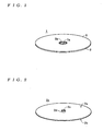
- FIG. 4 is a perspective external view of a pressing jig 13 in the manufacturing apparatus 11.
- FIG. 5 is a perspective external view of a pressing jig 14 in the manufacturing apparatus 11.
- FIG. 6 is a perspective external view of a punching blade 15 in the manufacturing apparatus 11.
- FIG. 7 is a cross-sectional view of a state where a resin layer 3 has been formed on the substrate 2x.
- FIG. 8 is a cross-sectional view of a state where the pressing jig 13 has been placed in contact with the rear surface of the substrate 2x.
- FIG. 9 is a cross-sectional view of a state where the pressing jig 14 has been placed in contact with the resin layer 3 to form a cut.
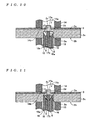
- FIG. 10 is a cross-sectional view of a state where a positioning convex part 17 has been placed in contact with a rim of the through-hole 2c in the substrate 2x.
- FIG. 11 is a cross-sectional view of a state where a blade main part 16 of the punching blade 15 has been pressed into a base surface of a concave part 2e.
- FIG. 12 is a cross-sectional view of a state where the center hole 1a has been punched out by the blade main part 16.
- FIG. 13 is a cross-sectional view of an optical disc 1.
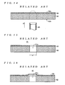
- FIG. 14 is a cross-sectional view of a state where a resin layer 53 has been formed on a substrate 52 during the manufacturing of the conventional optical disc 51.
- FIG. 15 is a cross-sectional view of an optical disc 51.
- FIG. 16 is a cross-sectional view of a state where the resin layer 53 in a periphery of a center hole 51a has been detached from the substrate 52.
- optical disc 1 manufactured according to the method of manufacturing an optical recording medium according to the present invention and the construction of a manufacturing apparatus 11 for manufacturing the optical disc 1 will be described with reference to the drawings.
- the optical disc 1 shown in FIG. 1 corresponds to an "optical recording medium" according to the present invention, and has one or more thin films (not shown) such as a light reflecting layer formed on one surface of a disc-like substrate (hereinafter, simply “substrate") 2 and a resin layer 3 formed so as to cover the thin films. It should be noted that for ease of understanding the present invention, description of the construction and method of forming the light reflecting layer and the like has been omitted. A center hole 1a for clamping in a recording/reproduction apparatus or the like is also formed in the optical disc 1.
- the substrate 2 is injection molded using a resin material such as polycarbonate.
- a resin material such as polycarbonate.
- a substrate 2 immediately after injection molding i.e., a substrate 2 in which the center hole 1a has not been formed
- the substrate 2x As shown in FIG. 2, a groove and land are formed on a surface 2a of the substrate 2x by the injection molding, and a cylindrical protruding part 2d, in which a positioning through-hole 2c (a "positioning hole” for the present invention) is formed, is formed in a central part of the surface 2a.
- a positioning through-hole 2c a "positioning hole” for the present invention
- a concave part 2e which will compose the center hole 1a when a base surface thereof is subsequently punched out, is formed in a central part of a rear surface 2b.
- a diameter L2 of the concave part 2e is formed equal to a diameter L1 of the center hole 1a (see FIG. 13) at 15mm, for example.
- the through-hole 2c is formed so that a diameter L3 thereof is 5mm, for example, and a center thereof matches a center of the concave part 2e.
- the resin layer 3 is a protective layer (cover layer) for protecting one or more thin layers (a light reflecting layer, a recording layer, and the like) formed on the substrate 2, and as one example is formed with a thickness T1 (see FIG. 13) of around 100 ⁇ m by applying a UV-curing resin material by spin coating.
- the manufacturing apparatus 11 shown in FIG. 3 corresponds to an "optical recording medium manufacturing apparatus" for the present invention and includes raising/lowering mechanisms 12a to 12c, pressing jigs 13, 14, a punching blade 15, an ultrasonic generator 18, and a control unit 19.
- the raising/lowering mechanisms 12a to 12c raise and lower the pressing jigs 13, 14 and the punching blade 15 under the control of the control unit 19.
- the pressing jig 13 corresponds to a "substrate pressing jig" for the present invention, and as shown in FIG. 4, a through-hole 13a for allowing the punching blade 15 to pass therethrough is formed in a central part thereof, and the pressing jig 13 is formed in an overall cylindrical shape with an upper surface thereof being formed flat.
- a diameter L5a of the through-hole 13a is set at around 16mm, for example.
- the pressing jig 14 corresponds to a "resin layer pressing jig" for the present invention, and as shown in FIG. 5, is formed in an overall cylindrical shape with a through-hole 14a for allowing a punched-out fragment punched out by the punching blade 15 when the center hole 1a is formed to pass therethrough being formed in a central part thereof.
- the lower surface of the pressing jig 14 (the upper surface in FIG. 5) is formed flat and a cut forming blade 14b is formed at a rim of the through-hole 14a.
- a diameter L5b of the through-hole 14a (that is, the internal diameter of the cut forming blade 14b) is set larger than the diameter L1 of the center hole 1a at around 16mm.
- a height H1 of the cut forming blade 14b is set at around 105 ⁇ m that is slightly greater than a thickness T1 of the resin layer 3 in accordance with the depth of the cut formed in the resin layer 3 when manufacturing the optical disc 1.
- the punching blade 15 includes a cylindrical blade main part 16, a positioning convex part 17 in the shape of a truncated cone, and a coil spring S (see FIG. 10).
- a diameter (external diameter) L6 of the blade main part 16 is set at 15mm, that is, equal to the diameter L1 of the center hole 1a, and the blade main part 16 is formed in a cylindrical shape with a through-hole 16a for allowing the positioning convex part 17 to pass therethrough being formed in a central part thereof.
- the positioning convex part 17 includes a contact part 17a, which is trapezoidal when viewed from the side and is placed in contact with a rim of the through-hole 2c of the substrate 2x when the center hole 1a is formed (punched out) using the blade main part 16, and a shaft 17b, which is integrally connected to a lower end of the contact part 17a and over which the coil spring S is disposed in the periphery.
- the positioning convex part 17 is formed so that a diameter L7 at an upper end of the contact part 17a is smaller than the through-hole 2c of the substrate 2x (as one example, around 4mm) and a diameter L8 at a lower end thereof is larger than the through-hole 2c (as one example, around 6mm).
- the positioning convex part 17 is attached to the blade main part 16 so as to be capable of up-down movement and is energized upward by the coil spring S so that the contact part 17a protrudes from an upper end of the blade main part 16.
- the ultrasonic generator 18 generates ultrasound under the control of the control unit 19 and causes the blade main part 16 of the punching blade 15 to vibrate by transmitting the ultrasound to the blade main part 16.
- the control unit 19 controls the operation of the raising/lowering mechanisms 12a to 12c and the ultrasonic generator 18.
- the surface 2a of the substrate 2x is spin coated with the resin material.
- the substrate 2x is rotated and the resin material is dripped onto the surface 2a.
- the resin material is dripped onto the periphery of an outer wall of the protruding part 2d.
- the resin material is spread out uniformly over the entire surface 2a by the centrifugal force that accompanies the rotation.
- the substrate 2x in this state is irradiated with UV rays to harden the resin material.
- the resin layer 3 is formed with a uniform thickness on the surface 2a of the substrate 2x.
- the control unit 19 first has the raising/lowering mechanism 12a raise the pressing jig 13 so that the pressing jig 13 contacts the rear surface 2b of the substrate 2x as shown in FIG. 8. Next, as shown in FIG. 9, the control unit 19 has the raising/lowering mechanism 12b lower the pressing jig 14 so that the cut forming blade 14b is pressed into the resin layer 3.
- the cut forming blade 14b is formed with a height H1 that is slightly larger than the thickness T1 of the resin layer 3, by having the raising/lowering mechanism 12b place the lower surface of the pressing jig 14 in contact with the surface of the resin layer 3, the blade of the cut forming blade 14b reaches the surface 2a of the substrate 2x. By doing so, a round cut is formed in the resin layer 3 with a diameter equal to the diameter L5b of the cut forming blade 14b (in this case, 16mm).
- the control unit 19 has the raising/lowering mechanisms 12a, 12b respectively place the pressing jigs 13, 14 in contact with the substrate 2x and while maintaining this state, has the raising/lowering mechanism 12c raise the punching blade 15.
- the control unit 19 causes the ultrasonic generator 18 to generate ultrasound and vibrate the blade main part 16.
- the contact part 17a of the positioning convex part 17 contacts (engages) the rim of the through-hole 2c inside the concave part 2e of the substrate 2x.
- the upper end of the contact part 17a engages the through-hole 2c to move the punching blade 15 relative to the substrate 2x so that the center of the punching blade 15 and the center of the substrate 2x are aligned.
- the blade main part 16 is placed in contact with the base surface of the concave part 2e and by further raising the blade main part 16, the blade edge of the blade main part 16 is pressed into the substrate 2x as shown in FIG. 11.
- the ultrasonic generator 18 causes the blade main part 16 to vibrate using ultrasound, the blade main part 16 can be smoothly pressed into the substrate 2x.
- the punching blade 15 is further raised and when the blade edge of the blade main part 16 has reached the surface 2a of the substrate 2x, as shown in FIG. 12, the periphery of the protruding part 2d in the substrate 2x is punched out to form the center hole 1a.
- the resin layer 3 inside the cut forming blade 14b of the pressing jig 14 is pulled off the surface 2a (the edge of the center hole 1a) of the substrate 2x by the force that raises the blade main part 16. By doing so, as shown in FIG.
- the center hole 1a is punched out and formed by pressing in the blade main part 16 of the punching blade 15 from the rear surface 2b side of the substrate 2x, so that detachment of the resin layer 3 from the surface 2a of the substrate 2x can be avoided when the center hole 1a is formed by pressing the blade main part 16 into the substrate 2x.
- the hole 3a whose diameter L4 is larger than the diameter L1 of the center hole 1a in the resin layer 3 of the optical disc 1 after manufacturing, when the optical disc 1 is clamped in a recording/reproduction apparatus, chafing of the resin layer 3 (the rim of the hole 3a) can be avoided, and as a result, detachment of the resin layer 3 during clamping can be avoided.
- the cut in the resin layer 3 in advance, it is possible to avoid the production of burrs in the resin layer 3 during formation of the center hole 1a by punching out.
- the cut forming blade 14b by forming the cut with a depth that reaches the surface 2a of the substrate 2x using the cut forming blade 14b, it is possible to reliably avoid the detachment of the resin layer 3 during formation of the center hole 1a by punching out. Also, according to the method of manufacturing and manufacturing apparatus 11 for the optical disc 1, by forming the cut by placing the pressing jig 13 in contact with the rear surface 2b of the substrate 2x and pressing the cut forming blade 14b into the resin layer 3 while this state is maintained, bending of the substrate 2x when the cut forming blade 14b is pressed into the resin layer 3 can be avoided, so that the resin layer 3 can be reliably cut by placing the blade edge of the cut forming blade 14b in contact with the surface 2a of the substrate 2x.
- the cut in the resin layer 3 by placing the pressing jig 14 on which the cut forming blade 14b has been formed with a height H1 in accordance with the depth of the cut to be formed in the resin layer 3 (in this case, a substantially equal height to the thickness T1 of the resin layer 3) in contact with the resin layer 3, compared to a method where the cut is formed by a dedicated cut forming blade, the cut forming blade is then placed on standby and a pressing jig that is dedicated to pressing the resin layer is placed in contact with the resin layer 3, the cut can be formed with the cut forming blade 14b by merely placing the pressing jig 14 in contact with the resin layer 3 and the blade main part 16 can be pressed in while the resin layer 3 is pressed in this state.
- the cut and the center hole 1a can be formed quickly and easily while avoiding damage and the like to the substrate 2x.
- the center hole 1a can be formed by smoothly pressing the blade main part 16 into the substrate 2x.
- the method of manufacturing the optical disc 1 by forming the concave part 2e with the same diameter as the center hole 1a at the formation position of the center hole 1a in the rear surface 2b of the substrate 2x when the substrate 2x is formed, compared to a method where the center hole 1a is formed by pressing the blade main part 16 into a substrate in which the concave part 2e has not been formed, the substrate punched out by the blade main part 16 can be formed thinly, so that the center hole 1a can be easily formed.
- the punching blade 15 by constructing the punching blade 15 so as to include the positioning convex part 17 which is formed so as to be able to engage the through-hole 2c formed in the center of the substrate 2x, which is attached to the center of the blade main part 16 via the coil spring S, and which protrudes further than the blade edge of the blade main part 16, it is possible to have the contact part 17a of the positioning convex part 17 contact the rim of the through-hole 2c before the blade main part 16 to align the center of the punching blade 15 and the center of the substrate 2x, so that the formation of the center hole 1a at an eccentric position can be reliably avoided.
- the present invention is not limited to the above embodiment.
- H1 height (here, 105 ⁇ m) that is slightly greater than the thickness T1 (here, 100 ⁇ m) of the resin layer 3
- the present invention is not limited to this, and by forming the cut forming blade 14b even higher (as one example, 120 ⁇ m), during the formation of the cut, it is possible to press the blade edge of the cut forming blade 14b into the substrate 2x and form a cut therein.
- the present invention is not limited to this, and it is also possible to use a construction where the pressing jig 14 is disposed below the substrate 2x and the pressing jig 13 and the punching blade 15 are disposed above. In this case, the substrate 2x is disposed with the rear surface 2b facing upward when forming the cut and the center hole 1a.
- this method of manufacturing an optical recording medium after a circular cut whose diameter is larger than the center hole is formed in the resin layer so as to surround a formation position of the center hole, a punching blade for forming the center hole is pressed into the disc-like substrate from a second surface-side of the disc-like substrate to form the center hole, so that detachment of the resin layer from the first surface of the disc-like substrate can be avoided when the center hole is formed by pressing the punching blade into the disc-like substrate.
Landscapes
- Engineering & Computer Science (AREA)
- Mechanical Engineering (AREA)
- Life Sciences & Earth Sciences (AREA)
- Forests & Forestry (AREA)
- Manufacturing & Machinery (AREA)
- Manufacturing Optical Record Carriers (AREA)
- Perforating, Stamping-Out Or Severing By Means Other Than Cutting (AREA)
- Optical Record Carriers And Manufacture Thereof (AREA)
Abstract
When manufacturing an optical recording medium by
forming a resin layer (3) on a surface (2a) of a substrate
(2x) and then forming a center hole (1a) that passes
through the substrate (2x) and the resin layer (3), a
method of manufacturing an optical recording medium
according to the present invention forms the center hole
(1a) by forming, in the resin layer (3), a circular cut
with a larger diameter than the center hole (1a) so as to
surround a formation position of the center hole (1a) and
then pressing in a punching blade (15) for forming the
center hole from a rear surface (2b) side of the substrate
(2x). By doing so, detachment of the resin layer (3) and
the production of burrs at or near the center hole (1a) can
be avoided while reducing the manufacturing cost.
Description
- The present invention relates to a method of manufacturing an optical recording medium, where a center hole that passes through a disc substrate and a resin layer is formed after the resin layer has been formed on one surface of the disc substrate, and to an optical recording medium manufacturing apparatus constructed so as to be able to manufacture an optical recording medium in accordance with such method.
- An optical disc (optical recording medium) such as a CD or DVD is normally manufactured by forming thin films such as a light reflecting layer by sputtering or the like on a disc-like substrate in whose surface grooves and lands have been formed by injection molding and then forming a resin layer as a protective layer (cover layer) by spin coating so as to cover the thin films. Also, when manufacturing a recordable optical disc such as a CD-R, a CD-RW, a DVD-R, and a DVD-RW, after thin films such as a recording layer and a light reflecting layer have been formed in order by sputtering or the like on the surface of a substrate, a resin layer as a protective layer is formed by spin coating so as to cover the thin films. When doing so, if fluctuations are produced in the thickness of the resin layer of a completed optical disc, it will be difficult to read and write recording data properly. Accordingly, when the resin layer is formed, it is necessary to spin coat a resin material for forming the resin layer across the entire substrate surface with a uniform thickness. To form a resin layer with a uniform thickness on a substrate by spin coating, the resin material should preferably be dripped onto a center of a substrate that is being rotated. However, since it is necessary to provide a center hole for clamping (chucking) in a recording/reproduction apparatus or the like in a center of the optical disc, it is difficult to drip the resin material at a center of the substrate during spin coating. For this reason, the applicant has developed a method of manufacturing an optical disc where a resin material is dripped to form a resin layer with a uniform thickness before the center hole is formed, and then the center hole is punched out so as to pass through the substrate and the resin layer.
- More specifically, as shown in FIG. 14, a resin material is spin coated onto a
surface 52a of a disc-like substrate 52, in a center of which a center hole has not been formed. When doing so, as shown by the broken line in FIG. 14, a UV-curing resin material, for example, is dripped onto a center (a position where the center hole will subsequently be formed) of thesubstrate 52 that is being rotated by an applying apparatus and the resin material spreads toward the outer edge of thesubstrate 52 due to the centrifugal force that accompanies the rotation. Here, by appropriately adjusting the rotational speed of thesubstrate 52, the resin material can be applied uniformly across the entire surface of thesubstrate 52. The resin material on thesubstrate 52 is then irradiated with UV rays to harden the resin material and thereby form aresin layer 53. After this, acylindrical punching blade 65 for forming thecenter hole 51a is pressed into thesubstrate 52 in the direction of the arrow A from arear surface 52b side to punch out the part shown by the broken line in FIG. 14. By doing so, as shown in FIG. 15, thecenter hole 51a with a diameter L1 of around 15mm is formed so as to pass through thesubstrate 52 and theresin layer 53, thereby completing theoptical disc 51. - On the other hand, Japanese Laid-Open Patent Publication No. H10-289489 discloses a method of manufacturing an optical recording medium where a light transmitting layer (18) is formed by dripping light-curing resin in a state where a center hole (10h) formed in a substrate (10) has been blocked by a blocking plate (21). In this method of manufacturing, a concave part (20) is formed in a periphery of the center hole when manufacturing the substrate, and when the light-curing resin is to be dripped, the blocking plate is fitted into this concave part to form a composite substrate and block the center hole. By doing so, it is possible to drip the light-curing resin on the center part of the substrate (in this case, the center part of the blocking plate). After the light-curing resin that has been dripped on the center part of the substrate has been spread out and cured with light, the blocking plate and the light transmitting resin are punched out by a center hole punching device (71) to form the center hole. By doing so, an optical recording medium is manufactured.
- By investigating the method of manufacturing the
optical disc 51 described above, the present inventors discovered the following problems to be solved. That is, after theresin layer 53 has been formed with uniform thickness on thesubstrate 52 in which a center hole has not been formed, thecenter hole 51a is punched out. In this case, theresin layer 53 formed on thesubstrate 52, is extremely thin at 100µm. For this reason, when thepunching blade 65 is pressed into thesubstrate 52 from therear surface 52b during the formation of thecenter hole 51a, as shown in FIG. 16, there is the risk of theresin layer 53 becoming detached from thesubstrate 52 in the periphery of the formation position of thecenter hole 51a. Here, since it is difficult to cleanly punch out thethin resin layer 53 using thepunching blade 65 when thecenter hole 51a is formed, there is also the risk of burrs being produced in the rim of thecenter hole 51a that has been punched out. In addition, even if theresin layer 53 is not detached when thecenter hole 51a is formed, there is the risk of theresin layer 53 becoming detached from thesubstrate 52 due to the rim of thecenter hole 51a being chafed by the recording/reproduction apparatus when theoptical disc 51 is clamped in a recording/reproduction apparatus. - On the other hand, in the method of manufacturing an optical recording medium disclosed in Japanese Laid-Open Patent Publication No. H10-289489, the center hole is formed by punching out using a center punching device from the side on which a light transmitting layer is formed. According to this method, although detachment of the optical transmitting layer can be avoided, in the same way as the method of manufacturing the
optical disc 51 described above, there is the risk of burrs being produced at the rim of the punched out center hole. Also, in this method of manufacturing an optical recording medium, the substrate and the blocking plate are formed separately and the blocking plate has to be fitted into the concave part when the light-curing resin is dripped, so that there is the problem of an increase in the manufacturing cost of the optical recording medium. - The present invention was conceived in view of the problems to be solved described above, and it is a principal object of the present invention to provide a method of manufacturing an optical recording medium and an optical recording medium manufacturing apparatus that can avoid detachment of the resin layer and the production of burrs at or near the center hole while reducing the manufacturing cost.
- A method of manufacturing an optical recording medium according to the present invention manufactures the optical recording medium by forming a resin layer on a first surface of a disc-like substrate and then forming a center hole that passes through the disc-like substrate and the resin layer, wherein the center hole is formed by forming, in the resin layer, a circular cut with a larger diameter than the center hole so as to surround a formation position of the center hole and then pressing a punching blade for forming the center hole into the disc-like substrate from a second surface side of the disc-like substrate.
- An optical recording medium manufacturing apparatus according to the present invention is capable of forming a center hole that passes through a disc-like substrate and a resin layer that has been formed on a first surface of the disc-like substrate, and includes: a cut forming blade that can form a circular cut with a larger diameter than the center hole in the resin layer so as to surround a formation position of the center hole; a punching blade for forming the center hole; and a control unit that controls movement of the cut forming blade and the punching blade, wherein the control unit forms the cut by moving the cut forming blade toward the resin layer and pressing the cut forming blade into the resin layer and then forms the center hole by moving the punching blade toward the disc-like substrate from a second surface side of the disc-like substrate and pressing in the punching blade.
- With the above method of manufacturing an optical recording medium and optical recording medium manufacturing apparatus, the center hole is formed by forming, in the resin layer, the circular cut with a larger diameter than the center hole so as to surround the formation position of the center hole and then pressing in the punching blade for forming the center hole from the second surface side of the disc-like substrate, so that it is possible to avoid detachment of the resin layer from the first surface of the disc-like substrate when the center hole is formed by pressing the punching blade into the disc-like substrate.
- Here, it is preferable to form the cut in the resin layer with a depth that reaches the first surface by the cut forming blade. By doing so, it is possible to avoid detachment of the resin layer during the punching out of the center hole more reliably. Since a hole with a larger diameter than the center hole is formed in the resin layer of the optical recording medium after manufacturing, chafing of the resin layer (the rim of the hole) when the optical recording medium is clamped in a recording/reproduction apparatus can be avoided, and as a result, detachment of the resin layer during clamping can be avoided. In addition, by forming the cut in the resin layer in advance, it is possible to avoid the production of burrs in the resin layer during the punching out of the center hole.
- Here, a substrate pressing jig should preferably be placed in contact with the second surface of the disc-like substrate and the contact should be maintained while the cut is formed in the resin layer. By doing so, bending of the disc-like substrate when the cut forming blade is pressed into the resin layer can be avoided, and as a result, the resin layer can be reliably cut when the blade edge of the cut forming blade is placed in contact with the first surface of the disc-like substrate.
- In addition, a resin layer pressing jig should preferably be placed in contact with the resin layer and the contact should be maintained while the center hole is formed by pressing the punching blade into the disc-like substrate. By doing so, it is possible to avoid bending of the disc-like substrate when the punching blade is pressed into the disc-like substrate, and as a result, it is possible to avoid detachment of the resin layer and damage to the disc-like substrate due to bending of the disc-like substrate. Also, by pressing the rim of the hole in the resin layer with the resin layer pressing jig, it is possible to avoid detachment at the rim of the hole when the punching blade has reached the first surface of the disc-like substrate.
- Also, the cut should preferably be formed in the resin layer by placing the resin layer pressing jig, in which a cut forming blade is formed with a height in accordance with a depth of the cut, in contact with the resin layer. By doing so, compared to a method where a cut is formed by a dedicated cut forming blade and then the cut forming blade is placed on standby and a pressing jig dedicated to pressing the resin layer is placed in contact with the resin layer, it is possible to form a cut with the cut forming blade simply by placing the resin layer pressing jig in contact with the resin layer, with it also being possible to press in the punching blade with the resin layer being pressed in this state. This means that it is possible to form the cut and the center hole quickly and easily while avoiding damage and the like to the disc substrate.
- In addition, the center hole should preferably be formed by pressing the punching blade into the disc-like substrate while vibration is applied to the punching blade using ultrasound. By doing so, the punching blade can be smoothly pressed into the disc-like substrate.
- Also, in the method of manufacturing an optical recording medium according to the present invention, when the disc-like substrate is molded, a concave part with an equal diameter or a substantially equal diameter to the center hole should preferably be formed at the formation position of the center hole in the second surface of the disc-like substrate. By doing so, compared to a method where the center hole is formed by pressing a punching blade into a substrate in which a concave part has not been formed, it is possible to form the material punched out by the punching blade thinly, so that the center hole can be formed easily. In this case, by forming the concave part with a diameter that is equal to the diameter of the center hole, it is possible to have the inner wall surface of the concave part function as a guide for the punching blade, and as a result, it is possible to avoid having the center hole formed in an eccentric position.
- Also, an optical recording medium manufacturing apparatus according to the present invention should preferably further include a positioning convex part that is formed so as to be capable of engaging a positioning hole formed in the disc-like substrate at a center of a formation position of the center hole, is attached to a center of the punching blade via an elastically deforming part, and is projected beyond a blade edge of the punching blade. With this construction, it is possible to have the positioning convex part contact the rim of the positioning hole before the punching blade to align the center of the punching blade and the center of the disc-like substrate, so that the formation of the center hole at an eccentric position can be reliably avoided.
- It should be noted that the disclosure of the present invention relates to a content of Japanese Patent Application 2002-276491 that was filed on 24 September 2002 and the entire content of which is herein incorporated by reference.
- FIG. 1 is a perspective external view of an
optical disc 1 according to an embodiment of the present invention. - FIG. 2 is a perspective external view of a
substrate 2x for theoptical disc 1. - FIG. 3 is a block diagram showing the construction of a
manufacturing apparatus 11. - FIG. 4 is a perspective external view of a
pressing jig 13 in themanufacturing apparatus 11. - FIG. 5 is a perspective external view of a
pressing jig 14 in themanufacturing apparatus 11. - FIG. 6 is a perspective external view of a
punching blade 15 in themanufacturing apparatus 11. - FIG. 7 is a cross-sectional view of a state where a
resin layer 3 has been formed on thesubstrate 2x. - FIG. 8 is a cross-sectional view of a state where the
pressing jig 13 has been placed in contact with the rear surface of thesubstrate 2x. - FIG. 9 is a cross-sectional view of a state where the
pressing jig 14 has been placed in contact with theresin layer 3 to form a cut. - FIG. 10 is a cross-sectional view of a state where a positioning
convex part 17 has been placed in contact with a rim of the through-hole 2c in thesubstrate 2x. - FIG. 11 is a cross-sectional view of a state where a blade
main part 16 of thepunching blade 15 has been pressed into a base surface of aconcave part 2e. - FIG. 12 is a cross-sectional view of a state where the
center hole 1a has been punched out by the blademain part 16. - FIG. 13 is a cross-sectional view of an
optical disc 1. - FIG. 14 is a cross-sectional view of a state where a
resin layer 53 has been formed on asubstrate 52 during the manufacturing of the conventionaloptical disc 51. - FIG. 15 is a cross-sectional view of an
optical disc 51. - FIG. 16 is a cross-sectional view of a state where the
resin layer 53 in a periphery of acenter hole 51a has been detached from thesubstrate 52. - Preferred embodiments of a method of manufacturing an optical recording medium and an optical recording medium manufacturing apparatus according to the present invention will now be described with reference to the attached drawings.
- First, an
optical disc 1 manufactured according to the method of manufacturing an optical recording medium according to the present invention and the construction of amanufacturing apparatus 11 for manufacturing theoptical disc 1 will be described with reference to the drawings. - The
optical disc 1 shown in FIG. 1 corresponds to an "optical recording medium" according to the present invention, and has one or more thin films (not shown) such as a light reflecting layer formed on one surface of a disc-like substrate (hereinafter, simply "substrate") 2 and aresin layer 3 formed so as to cover the thin films. It should be noted that for ease of understanding the present invention, description of the construction and method of forming the light reflecting layer and the like has been omitted. Acenter hole 1a for clamping in a recording/reproduction apparatus or the like is also formed in theoptical disc 1. - Before the
optical disc 1 is manufactured, thesubstrate 2 is injection molded using a resin material such as polycarbonate. It should be noted that in the following explanation, to distinguish between thesubstrate 2 of a completedoptical disc 1 and thesubstrate 2 immediately after injection molding, asubstrate 2 immediately after injection molding (i.e., asubstrate 2 in which thecenter hole 1a has not been formed) is referred to as thesubstrate 2x. As shown in FIG. 2, a groove and land are formed on asurface 2a of thesubstrate 2x by the injection molding, and a cylindrical protrudingpart 2d, in which a positioning through-hole 2c (a "positioning hole" for the present invention) is formed, is formed in a central part of thesurface 2a. In addition, as shown in FIG. 7, aconcave part 2e, which will compose thecenter hole 1a when a base surface thereof is subsequently punched out, is formed in a central part of arear surface 2b. In this case, a diameter L2 of theconcave part 2e is formed equal to a diameter L1 of thecenter hole 1a (see FIG. 13) at 15mm, for example. The through-hole 2c is formed so that a diameter L3 thereof is 5mm, for example, and a center thereof matches a center of theconcave part 2e. Theresin layer 3 is a protective layer (cover layer) for protecting one or more thin layers (a light reflecting layer, a recording layer, and the like) formed on thesubstrate 2, and as one example is formed with a thickness T1 (see FIG. 13) of around 100µm by applying a UV-curing resin material by spin coating. - On the other hand, the
manufacturing apparatus 11 shown in FIG. 3 corresponds to an "optical recording medium manufacturing apparatus" for the present invention and includes raising/loweringmechanisms 12a to 12c, pressingjigs punching blade 15, anultrasonic generator 18, and acontrol unit 19. The raising/loweringmechanisms 12a to 12c raise and lower thepressing jigs punching blade 15 under the control of thecontrol unit 19. Thepressing jig 13 corresponds to a "substrate pressing jig" for the present invention, and as shown in FIG. 4, a through-hole 13a for allowing thepunching blade 15 to pass therethrough is formed in a central part thereof, and thepressing jig 13 is formed in an overall cylindrical shape with an upper surface thereof being formed flat. In this case, a diameter L5a of the through-hole 13a is set at around 16mm, for example. Thepressing jig 14 corresponds to a "resin layer pressing jig" for the present invention, and as shown in FIG. 5, is formed in an overall cylindrical shape with a through-hole 14a for allowing a punched-out fragment punched out by thepunching blade 15 when thecenter hole 1a is formed to pass therethrough being formed in a central part thereof. The lower surface of the pressing jig 14 (the upper surface in FIG. 5) is formed flat and acut forming blade 14b is formed at a rim of the through-hole 14a. In this case, a diameter L5b of the through-hole 14a (that is, the internal diameter of thecut forming blade 14b) is set larger than the diameter L1 of thecenter hole 1a at around 16mm. A height H1 of thecut forming blade 14b is set at around 105µm that is slightly greater than a thickness T1 of theresin layer 3 in accordance with the depth of the cut formed in theresin layer 3 when manufacturing theoptical disc 1. - As shown in FIG. 6, the
punching blade 15 includes a cylindrical blademain part 16, a positioningconvex part 17 in the shape of a truncated cone, and a coil spring S (see FIG. 10). A diameter (external diameter) L6 of the blademain part 16 is set at 15mm, that is, equal to the diameter L1 of thecenter hole 1a, and the blademain part 16 is formed in a cylindrical shape with a through-hole 16a for allowing the positioningconvex part 17 to pass therethrough being formed in a central part thereof. The positioningconvex part 17 includes acontact part 17a, which is trapezoidal when viewed from the side and is placed in contact with a rim of the through-hole 2c of thesubstrate 2x when thecenter hole 1a is formed (punched out) using the blademain part 16, and ashaft 17b, which is integrally connected to a lower end of thecontact part 17a and over which the coil spring S is disposed in the periphery. Here, the positioningconvex part 17 is formed so that a diameter L7 at an upper end of thecontact part 17a is smaller than the through-hole 2c of thesubstrate 2x (as one example, around 4mm) and a diameter L8 at a lower end thereof is larger than the through-hole 2c (as one example, around 6mm). In addition, the positioningconvex part 17 is attached to the blademain part 16 so as to be capable of up-down movement and is energized upward by the coil spring S so that thecontact part 17a protrudes from an upper end of the blademain part 16. - The
ultrasonic generator 18 generates ultrasound under the control of thecontrol unit 19 and causes the blademain part 16 of thepunching blade 15 to vibrate by transmitting the ultrasound to the blademain part 16. Thecontrol unit 19 controls the operation of the raising/loweringmechanisms 12a to 12c and theultrasonic generator 18. It should be noted that for ease of understanding the present invention, the construction of the applying apparatus that spin coats thesubstrate 2x with the resin material and the method of applying have been omitted from the explanation and drawings. - Next, the method of manufacturing the
optical disc 1 will be described with reference to the drawings. It should be noted that the injection molding of thesubstrate 2x and the formation of thin layers on thesurface 2a of thesubstrate 2x are assumed to have been completed already. - First, the
surface 2a of thesubstrate 2x is spin coated with the resin material. When doing so, in a state where thesubstrate 2x is set in an applying apparatus, thesubstrate 2x is rotated and the resin material is dripped onto thesurface 2a. At this time, as shown by the broken line in FIG. 7, by dripping the resin material onto the periphery of an outer wall of theprotruding part 2d, it is possible to uniformly spread out the resin material in the same way as a conventional spin coating method developed by the applicant (a method where resin material is dripped at a central part of a substrate in which no center hole has been formed). Next, by appropriately adjusting the rotational speed of thesubstrate 2x, the resin material is spread out uniformly over theentire surface 2a by the centrifugal force that accompanies the rotation. After this, thesubstrate 2x in this state is irradiated with UV rays to harden the resin material. By doing so, as shown in FIG. 7, theresin layer 3 is formed with a uniform thickness on thesurface 2a of thesubstrate 2x. - After this, the
center hole 1a is formed in thesubstrate 2x on which theresin layer 3 has been formed. At this time, thecontrol unit 19 first has the raising/lowering mechanism 12a raise thepressing jig 13 so that thepressing jig 13 contacts therear surface 2b of thesubstrate 2x as shown in FIG. 8. Next, as shown in FIG. 9, thecontrol unit 19 has the raising/lowering mechanism 12b lower thepressing jig 14 so that thecut forming blade 14b is pressed into theresin layer 3. Here, since thecut forming blade 14b is formed with a height H1 that is slightly larger than the thickness T1 of theresin layer 3, by having the raising/lowering mechanism 12b place the lower surface of thepressing jig 14 in contact with the surface of theresin layer 3, the blade of thecut forming blade 14b reaches thesurface 2a of thesubstrate 2x. By doing so, a round cut is formed in theresin layer 3 with a diameter equal to the diameter L5b of thecut forming blade 14b (in this case, 16mm). - After this, the
control unit 19 has the raising/loweringmechanisms pressing jigs substrate 2x and while maintaining this state, has the raising/lowering mechanism 12c raise thepunching blade 15. At the same time, thecontrol unit 19 causes theultrasonic generator 18 to generate ultrasound and vibrate the blademain part 16. At this time, as shown in FIG. 10, first thecontact part 17a of the positioningconvex part 17 contacts (engages) the rim of the through-hole 2c inside theconcave part 2e of thesubstrate 2x. Here, even if the center of thepunching blade 15 and the center of thesubstrate 2x (that is, the center of the through-hole 2c) are displaced, the upper end of thecontact part 17a engages the through-hole 2c to move thepunching blade 15 relative to thesubstrate 2x so that the center of thepunching blade 15 and the center of thesubstrate 2x are aligned. Next, by further raising thepunching blade 15 using the raising/lowering mechanism 12c, the blademain part 16 is placed in contact with the base surface of theconcave part 2e and by further raising the blademain part 16, the blade edge of the blademain part 16 is pressed into thesubstrate 2x as shown in FIG. 11. At this time, since theultrasonic generator 18 causes the blademain part 16 to vibrate using ultrasound, the blademain part 16 can be smoothly pressed into thesubstrate 2x. - After this, the
punching blade 15 is further raised and when the blade edge of the blademain part 16 has reached thesurface 2a of thesubstrate 2x, as shown in FIG. 12, the periphery of theprotruding part 2d in thesubstrate 2x is punched out to form thecenter hole 1a. At this time, since the cut has been formed in theresin layer 3 by thecut forming blade 14b, when the blade edge of the blademain part 16 has reached thesurface 2a, theresin layer 3 inside thecut forming blade 14b of thepressing jig 14 is pulled off thesurface 2a (the edge of thecenter hole 1a) of thesubstrate 2x by the force that raises the blademain part 16. By doing so, as shown in FIG. 13, ahole 3a with a larger diameter L4 (in this case, 16mm, which is equal to the diameter L5b of thecut forming blade 14b) than the diameter L1 of thecenter hole 1a is formed in theresin layer 3, thereby completing theoptical disc 1. - In this way, according to the method of manufacturing and the
manufacturing apparatus 11 for theoptical disc 1, after a circular cut with a larger diameter than thecenter hole 1a has been formed in theresin layer 3 by thecut forming blade 14b of thepressing jig 14 so as to surround the formation position of thecenter hole 1a, thecenter hole 1a is punched out and formed by pressing in the blademain part 16 of thepunching blade 15 from therear surface 2b side of thesubstrate 2x, so that detachment of theresin layer 3 from thesurface 2a of thesubstrate 2x can be avoided when thecenter hole 1a is formed by pressing the blademain part 16 into thesubstrate 2x. In addition, by forming thehole 3a whose diameter L4 is larger than the diameter L1 of thecenter hole 1a in theresin layer 3 of theoptical disc 1 after manufacturing, when theoptical disc 1 is clamped in a recording/reproduction apparatus, chafing of the resin layer 3 (the rim of thehole 3a) can be avoided, and as a result, detachment of theresin layer 3 during clamping can be avoided. In addition, by forming the cut in theresin layer 3 in advance, it is possible to avoid the production of burrs in theresin layer 3 during formation of thecenter hole 1a by punching out. Here, by forming the cut with a depth that reaches thesurface 2a of thesubstrate 2x using thecut forming blade 14b, it is possible to reliably avoid the detachment of theresin layer 3 during formation of thecenter hole 1a by punching out. Also, according to the method of manufacturing andmanufacturing apparatus 11 for theoptical disc 1, by forming the cut by placing thepressing jig 13 in contact with therear surface 2b of thesubstrate 2x and pressing thecut forming blade 14b into theresin layer 3 while this state is maintained, bending of thesubstrate 2x when thecut forming blade 14b is pressed into theresin layer 3 can be avoided, so that theresin layer 3 can be reliably cut by placing the blade edge of thecut forming blade 14b in contact with thesurface 2a of thesubstrate 2x. - Also, according to the method of manufacturing and
manufacturing apparatus 11 for theoptical disc 1, by forming thecenter hole 1a by placing thepressing jig 14 in contact with theresin layer 3 and pressing the blademain part 16 into thesubstrate 2x while this state is maintained, bending of thesubstrate 2x when the blademain part 16 is pressed into thesubstrate 2x can be avoided, so that damage to thesubstrate 2x and detachment of theresin layer 3 due to bending of thesubstrate 2x can be avoided. In addition, by pressing the rim of thehole 3a of theresin layer 3 using thepressing jig 14, detachment of theresin layer 3 at the rim of thehole 3a when the blademain part 16 reaches thesurface 2a of thesubstrate 2x can be avoided. Also, according to the method of manufacturing andmanufacturing apparatus 11 for theoptical disc 1, by forming the cut in theresin layer 3 by placing thepressing jig 14 on which thecut forming blade 14b has been formed with a height H1 in accordance with the depth of the cut to be formed in the resin layer 3 (in this case, a substantially equal height to the thickness T1 of the resin layer 3) in contact with theresin layer 3, compared to a method where the cut is formed by a dedicated cut forming blade, the cut forming blade is then placed on standby and a pressing jig that is dedicated to pressing the resin layer is placed in contact with theresin layer 3, the cut can be formed with thecut forming blade 14b by merely placing thepressing jig 14 in contact with theresin layer 3 and the blademain part 16 can be pressed in while theresin layer 3 is pressed in this state. For this reason, the cut and thecenter hole 1a can be formed quickly and easily while avoiding damage and the like to thesubstrate 2x. In addition, according to the method of manufacturing andmanufacturing apparatus 11 for theoptical disc 1, by pressing the blademain part 16 into thesubstrate 2x while applying ultrasound generated by theultrasonic generator 18 to the blademain part 16, thecenter hole 1a can be formed by smoothly pressing the blademain part 16 into thesubstrate 2x. - According to the method of manufacturing the
optical disc 1, by forming theconcave part 2e with the same diameter as thecenter hole 1a at the formation position of thecenter hole 1a in therear surface 2b of thesubstrate 2x when thesubstrate 2x is formed, compared to a method where thecenter hole 1a is formed by pressing the blademain part 16 into a substrate in which theconcave part 2e has not been formed, the substrate punched out by the blademain part 16 can be formed thinly, so that thecenter hole 1a can be easily formed. In this case, by forming theconcave part 2e with the diameter L2 that is equal to the diameter L1 of thecenter hole 1a, it is possible to have an inner wall surface of theconcave part 2e function as a guide for the blademain part 16, and as a result, the formation of thecenter hole 1a in an eccentric position can be avoided. Additionally, according to themanufacturing apparatus 11, by constructing thepunching blade 15 so as to include the positioningconvex part 17 which is formed so as to be able to engage the through-hole 2c formed in the center of thesubstrate 2x, which is attached to the center of the blademain part 16 via the coil spring S, and which protrudes further than the blade edge of the blademain part 16, it is possible to have thecontact part 17a of the positioningconvex part 17 contact the rim of the through-hole 2c before the blademain part 16 to align the center of thepunching blade 15 and the center of thesubstrate 2x, so that the formation of thecenter hole 1a at an eccentric position can be reliably avoided. - It should be noted that the present invention is not limited to the above embodiment. For example, although an example where the
cut forming blade 14b is formed with a height H1 (here, 105µm) that is slightly greater than the thickness T1 (here, 100µm) of theresin layer 3 has been described in the above embodiment, the present invention is not limited to this, and by forming thecut forming blade 14b even higher (as one example, 120µm), during the formation of the cut, it is possible to press the blade edge of thecut forming blade 14b into thesubstrate 2x and form a cut therein. By doing so, it is possible to cut off theresin layer 3 more reliably, and as a result, it is possible to avoid a situation where theresin layer 3 that should be punched out together with thesubstrate 2x during the formation of thecenter hole 1a is left in the periphery of thecenter hole 1a. Also, although an example where the cut and thecenter hole 1a are formed by disposing thepressing jig 14 above thesubstrate 2x and disposing thepressing jig 13 and thepunching blade 15 below has been described in the above embodiment, the present invention is not limited to this, and it is also possible to use a construction where thepressing jig 14 is disposed below thesubstrate 2x and thepressing jig 13 and thepunching blade 15 are disposed above. In this case, thesubstrate 2x is disposed with therear surface 2b facing upward when forming the cut and thecenter hole 1a. - As described above, according to this method of manufacturing an optical recording medium, after a circular cut whose diameter is larger than the center hole is formed in the resin layer so as to surround a formation position of the center hole, a punching blade for forming the center hole is pressed into the disc-like substrate from a second surface-side of the disc-like substrate to form the center hole, so that detachment of the resin layer from the first surface of the disc-like substrate can be avoided when the center hole is formed by pressing the punching blade into the disc-like substrate. By doing so, it is possible to realize a method of manufacturing an optical recording medium that can avoid the detachment of the resin layer and the production of burrs in the periphery of the center hole, while reducing the manufacturing cost.
Claims (14)
- A method of manufacturing an optical recording medium by forming a resin layer on a first surface of a disc-like substrate and then forming a center hole that passes through the disc-like substrate and the resin layer,
wherein the center hole is formed by forming, in the resin layer, a circular cut with a larger diameter than the center hole so as to surround a formation position of the center hole and then pressing a punching blade for forming the center hole into the disc-like substrate from a second surface side of the disc-like substrate. - A method of manufacturing an optical recording medium according to Claim 1,
wherein the cut is formed in the resin layer with a depth that reaches the first surface. - A method of manufacturing an optical recording medium according to Claim 1,
wherein a substrate pressing jig is placed in contact with the second surface of the disc-like substrate and the contact is maintained while the cut is formed in the resin layer. - A method of manufacturing an optical recording medium according to Claim 1,
wherein a resin layer pressing jig is placed in contact with the resin layer and the contact is maintained while the center hole is formed by pressing the punching blade into the disc-like substrate. - A method of manufacturing an optical recording medium according to Claim 4,
wherein the cut is formed in the resin layer by placing the resin layer pressing jig, in which a cut forming blade is formed with a height in accordance with a depth of the cut, in contact with the resin layer. - A method of manufacturing an optical recording medium according to Claim 1,
wherein the center hole is formed by pressing the punching blade into the disc-like substrate while the punching blade is vibrated by ultrasound. - A method of manufacturing an optical recording medium according to Claim 1,
wherein when the disc-like substrate is molded, a concave part with an equal diameter or a substantially equal diameter to the center hole is formed at the formation position of the center hole in the second surface of the disc-like substrate. - An optical recording medium manufacturing apparatus capable of forming a center hole that passes through a disc-like substrate and a resin layer that has been formed on a first surface of the disc-like substrate,
the optical recording medium manufacturing apparatus comprising:wherein the control unit forms the cut by moving the cut forming blade toward the resin layer and pressing the cut forming blade into the resin layer and then forms the center hole by moving the punching blade toward the disc-like substrate from a second surface side of the disc-like substrate and pressing in the punching blade.a cut forming blade that can form a circular cut with a larger diameter than the center hole in the resin layer so as to surround a formation position of the center hole;a punching blade for forming the center hole; anda control unit that controls movement of the cut forming blade and the punching blade, - An optical recording medium manufacturing apparatus according to Claim 8,
wherein the cut forming blade is constructed so as to be capable of forming the cut with a depth that reaches the first surface. - An optical recording medium manufacturing apparatus according to Claim 8,
further comprising a substrate pressing jig that presses the second surface of the disc-like substrate in accordance with control by the control unit during formation of the cut,
wherein the control unit forms the cut by placing the substrate pressing jig in contact with the second surface of the disc-like substrate and moving the cut forming blade while maintaining the contact. - An optical recording medium manufacturing apparatus according to Claim 8,
further comprising a resin layer pressing jig that presses the resin layer in accordance with control by the control unit during formation of the center hole,
wherein the control unit forms the center hole by placing the resin layer pressing jig in contact with the resin layer and moving the punching blade while maintaining the contact. - An optical recording medium manufacturing apparatus according to Claim 11,
wherein the resin layer pressing jig is constructed so as to include the cut forming blade whose height is in accordance with a depth of the cut,
and the control unit forms the cut in the resin layer by placing the resin layer pressing jig in contact with the resin layer. - An optical recording medium manufacturing apparatus according to Claim 8,
further comprising an ultrasonic generator that applies vibration to the punching blade using ultrasound,
wherein the control unit forms the center hole by pressing the punching blade into the disc-like substrate while causing the ultrasonic generator to apply vibration to the punching blade using the ultrasound. - An optical recording medium manufacturing apparatus according to Claim 8,
further comprising a positioning convex part that is formed so as to be capable of engaging a positioning hole formed in the disc-like substrate in a center of a formation position of the center hole, is attached to a center of the punching blade via an elastically deforming part, and is projected beyond a blade edge of the punching blade.
Applications Claiming Priority (3)
| Application Number | Priority Date | Filing Date | Title |
|---|---|---|---|
| JP2002276491 | 2002-09-24 | ||
| JP2002276491A JP4270830B2 (en) | 2002-09-24 | 2002-09-24 | Optical recording medium manufacturing method and optical recording medium manufacturing apparatus |
| PCT/JP2003/011941 WO2004029952A1 (en) | 2002-09-24 | 2003-09-18 | Optical recording medium producing method, and optical recording medium producing device |
Publications (1)
| Publication Number | Publication Date |
|---|---|
| EP1551019A1 true EP1551019A1 (en) | 2005-07-06 |
Family
ID=32040383
Family Applications (1)
| Application Number | Title | Priority Date | Filing Date |
|---|---|---|---|
| EP03798417A Withdrawn EP1551019A1 (en) | 2002-09-24 | 2003-09-18 | Optical recording medium producing method, and optical recording medium producing device |
Country Status (7)
| Country | Link |
|---|---|
| US (1) | US7625506B2 (en) |
| EP (1) | EP1551019A1 (en) |
| JP (1) | JP4270830B2 (en) |
| CN (1) | CN1679098A (en) |
| AU (1) | AU2003266536A1 (en) |
| TW (1) | TWI228717B (en) |
| WO (1) | WO2004029952A1 (en) |
Families Citing this family (5)
| Publication number | Priority date | Publication date | Assignee | Title |
|---|---|---|---|---|
| JP2003217190A (en) * | 2002-01-17 | 2003-07-31 | Tdk Corp | Manufacturing method of disk optical recording medium and disk optical recording medium |
| JP2004265495A (en) | 2003-02-28 | 2004-09-24 | Tdk Corp | Optical recording medium manufacturing device |
| JP6307217B2 (en) * | 2013-02-07 | 2018-04-04 | 日本発條株式会社 | Damper punching method, punching device, and sticking device |
| CN103878871B (en) * | 2014-02-25 | 2017-08-25 | 韩文强 | A kind of prefabricated pipeline preformed hole cutter |
| CN112339006B (en) * | 2020-10-13 | 2022-08-02 | 江苏艾锐博精密金属科技有限公司 | Die-cutting adhesive-piercing punching structure and process thereof |
Family Cites Families (11)
| Publication number | Priority date | Publication date | Assignee | Title |
|---|---|---|---|---|
| JPS5845637A (en) | 1981-09-08 | 1983-03-16 | Matsushita Electric Ind Co Ltd | Manufacture for optical recording disc |
| JPS61175946A (en) | 1985-01-29 | 1986-08-07 | Victor Co Of Japan Ltd | Production of information recording medium |
| JPS63203308A (en) | 1987-02-20 | 1988-08-23 | Daicel Chem Ind Ltd | Method for forming central hole of disk |
| JP3229367B2 (en) | 1992-05-29 | 2001-11-19 | 株式会社リコー | Stamper punching equipment |
| JPH1040584A (en) * | 1996-07-22 | 1998-02-13 | Matsushita Electric Ind Co Ltd | Method of manufacturing disk body such as optical disk |
| JP4066471B2 (en) | 1997-02-14 | 2008-03-26 | ソニー株式会社 | Optical recording medium manufacturing method and manufacturing apparatus |
| JP4433632B2 (en) | 2001-03-29 | 2010-03-17 | ソニー株式会社 | Manufacturing method of optical recording medium |
| JP4248197B2 (en) * | 2002-07-04 | 2009-04-02 | Tdk株式会社 | Optical recording medium, optical recording medium manufacturing method and manufacturing apparatus |
| JP2004227671A (en) * | 2003-01-23 | 2004-08-12 | Tdk Corp | Optical recording medium manufacturing equipment |
| JP2004227672A (en) * | 2003-01-23 | 2004-08-12 | Tdk Corp | Optical recording medium manufacturing equipment |
| JP2004265495A (en) * | 2003-02-28 | 2004-09-24 | Tdk Corp | Optical recording medium manufacturing device |
-
2002
- 2002-09-24 JP JP2002276491A patent/JP4270830B2/en not_active Expired - Fee Related
-
2003
- 2003-09-18 EP EP03798417A patent/EP1551019A1/en not_active Withdrawn
- 2003-09-18 AU AU2003266536A patent/AU2003266536A1/en not_active Abandoned
- 2003-09-18 CN CNA038206145A patent/CN1679098A/en active Pending
- 2003-09-18 US US10/528,778 patent/US7625506B2/en not_active Expired - Fee Related
- 2003-09-18 WO PCT/JP2003/011941 patent/WO2004029952A1/en not_active Ceased
- 2003-09-19 TW TW092125854A patent/TWI228717B/en not_active IP Right Cessation
Non-Patent Citations (1)
| Title |
|---|
| See references of WO2004029952A1 * |
Also Published As
| Publication number | Publication date |
|---|---|
| US20060177534A1 (en) | 2006-08-10 |
| TW200406761A (en) | 2004-05-01 |
| JP4270830B2 (en) | 2009-06-03 |
| CN1679098A (en) | 2005-10-05 |
| WO2004029952A1 (en) | 2004-04-08 |
| AU2003266536A1 (en) | 2004-04-19 |
| JP2004118880A (en) | 2004-04-15 |
| TWI228717B (en) | 2005-03-01 |
| US7625506B2 (en) | 2009-12-01 |
Similar Documents
| Publication | Publication Date | Title |
|---|---|---|
| JP2004265495A (en) | Optical recording medium manufacturing device | |
| US7625506B2 (en) | Optical recording medium producing method, and optical recording medium producing device | |
| US4787009A (en) | Optical disk | |
| JP2004118952A (en) | Intermediate for optical recording medium, molding metal mold, molding apparatus, and manufacturing method of optical recording medium | |
| US20040212122A1 (en) | Information recording medium preform, method of manufacturing an information recording medium, and manufacturing apparatus for an information recording medium | |
| EP1450360A1 (en) | Method and device for manufacturing optical recording medium | |
| US7680018B2 (en) | Optical recording medium, and manufacturing method and manufacturing device thereof | |
| US20060073284A1 (en) | Applied film forming apparatus and applied film forming method | |
| JP4109216B2 (en) | Information recording medium | |
| TW583661B (en) | Optical disk and its manufacturing method, manufacturing method of disk substrate | |
| JP2005235285A (en) | Substrate for information recording medium, and information recording medium manufacturing method | |
| US20040032035A1 (en) | Optical disc cover layer formation method and optical disc cover layer formation device | |
| JP2005235286A (en) | Method and device for manufacturing information recording medium | |
| WO2004064058A1 (en) | Turn table device manufacturing method and turn table device | |
| TW200807409A (en) | Disc substrate, forming die for the same, blue-ray disc (r) manufactured using disc substrate, and manufacturing method of blue-ray disc | |
| US7512960B2 (en) | Hub-mounted optical disk having a reduced height | |
| JP2003059123A (en) | Method of manufacturing optical disk | |
| JP2005302201A (en) | Information recording medium | |
| JPH06168560A (en) | Optical disk substrate and method for adhering hub of optical disk substrate | |
| JP2005125485A (en) | Cutter, punching machine, information recording medium manufacturing device and central hole forming method | |
| JP2006212596A (en) | Coating film formation apparatus and coating film formation method | |
| WO2000058068A1 (en) | Method for making a substrate for a digital versatile disc and digital versatile disc including the substrate | |
| JP2006181427A (en) | Apparatus and method for forming coating film | |
| JP2003228892A (en) | Method for manufacturing disc-shaped optical recording medium | |
| JPH06290491A (en) | Disk base and die unit for molding disk base |
Legal Events
| Date | Code | Title | Description |
|---|---|---|---|
| PUAI | Public reference made under article 153(3) epc to a published international application that has entered the european phase |
Free format text: ORIGINAL CODE: 0009012 |
|
| 17P | Request for examination filed |
Effective date: 20050419 |
|
| AK | Designated contracting states |
Kind code of ref document: A1 Designated state(s): AT BE BG CH CY CZ DE DK EE ES FI FR GB GR HU IE IT LI LU MC NL PT RO SE SI SK TR |
|
| AX | Request for extension of the european patent |
Extension state: AL LT LV MK |
|
| DAX | Request for extension of the european patent (deleted) | ||
| STAA | Information on the status of an ep patent application or granted ep patent |
Free format text: STATUS: THE APPLICATION HAS BEEN WITHDRAWN |
|
| 18W | Application withdrawn |
Effective date: 20060814 |