EP1550982A2 - Vorrichtung zur Kalibrierung eines Bildsensorsystems - Google Patents
Vorrichtung zur Kalibrierung eines Bildsensorsystems Download PDFInfo
- Publication number
- EP1550982A2 EP1550982A2 EP04105377A EP04105377A EP1550982A2 EP 1550982 A2 EP1550982 A2 EP 1550982A2 EP 04105377 A EP04105377 A EP 04105377A EP 04105377 A EP04105377 A EP 04105377A EP 1550982 A2 EP1550982 A2 EP 1550982A2
- Authority
- EP
- European Patent Office
- Prior art keywords
- sensor system
- image sensor
- motor vehicle
- image
- steering angle
- Prior art date
- Legal status (The legal status is an assumption and is not a legal conclusion. Google has not performed a legal analysis and makes no representation as to the accuracy of the status listed.)
- Granted
Links
Images

Classifications
-
- G—PHYSICS
- G06—COMPUTING OR CALCULATING; COUNTING
- G06T—IMAGE DATA PROCESSING OR GENERATION, IN GENERAL
- G06T7/00—Image analysis
- G06T7/80—Analysis of captured images to determine intrinsic or extrinsic camera parameters, i.e. camera calibration
Definitions
- the invention relates to a device for calibrating at least one image sensor system, wherein the image sensor system is arranged in a motor vehicle.
- a reversing camera system wherein a Camera with a wide-angle lens a video image of the situation behind a motor vehicle receives.
- the video image is presented in a display to the driver.
- guides in the video image are used for Visualization of the distance of the motor vehicle to obstacles or objects. Further show the guides depending on the steering wheel a driving tube in which move the motor vehicle at a backward movement with a constant steering angle would. This proposal has the advantage that the driver is easier to park.
- US 2001/0006554 A1 of 5 July 2001 discloses a device for calibrating a Camera of a motor vehicle, wherein for calibration a two-dimensional Calibration feature is mounted on the floor. After the motor vehicle in a is turned off predetermined position, the camera is calibrated by means of the calibration feature.
- the apparatus described below for calibrating at least one Image sensor system having the features of independent claim 1 has the advantage that an exact positioning of the motor vehicle with respect to the calibration object is not is required.
- Calibration objects are either expensive wheel alignment or roller dynamometers or Markings on the roadway required for positioning to determine the location of the road Specify rear axle, or the location of the calibration object is about additional technical Equipment in manufacturing or in workshops set. This is high cost connected, for example, the use of test benches, especially in manufacturing high Costs caused. Furthermore, test stands are not available in all workshops.
- the exact one Positioning of the motor vehicle by means of markings for positioning on the roadway is difficult as it depends on the skill of the driver. Also the use of additional technical equipment causes high costs.
- the hereinafter described device has the advantage of a precise, simple and at the same time cost-effective calibration of an image sensor system in a motor vehicle, in particular in a reversing camera system.
- the image sensor system at least a part of the rear Travel compartment of the motor vehicle detects, in particular, that the image sensor system component a rearview camera system is.
- the calibration object has at least one two-dimensional marking on the Fahrbahnebene includes, wherein preferably the at least one mark in the form and Size at least forms a parking mark for motor vehicles.
- the two-dimensional Marker is for example a road marking, such as an arrow, and / or a Park place marker.
- a road test field is of the simplest construction and therefore inexpensive.
- the level road test field is increasing in production and / or in a workshop little space, as it is passable and accessible.
- the two-dimensional marking as a thin plate and / or adhesive film and / or as Color application is realized because such a mark inexpensive, resistant to aging and is resistant.
- parking markings Parking space markings
- a further advantage is that the device is configured such that by means of forward travel and / or reversing the motor vehicle from the first position of the image sensor system second position of the image sensor system is taken.
- the configuration of the device in the forward drive has the advantage that the device, the image sensor system in the Can calibrate the majority of operating time, since the forward drive is the most common mode of operation Motor vehicle is.
- the steering angle of the motor vehicle between the right half Steering angle and the right maximum steering angle and / or the steering angle of the Motor vehicle between the left half steering angle and the left maximum Steering lock is.
- the steering angle of the motor vehicle maximum This increases the accuracy of the calibration. At the same time it goes in advantageously an increase in the accuracy of the representation of the driving tube associated.
- the device is configured such that the device the Image sensor system calibrated in dependence on image signals of the calibration object, wherein the Device has stored at least one geometric feature of the calibration object.
- One geometric feature is, for example, the length and / or width of a Road markings and / or a parking mark.
- Such a device has the Advantage that the accuracy of the calibration is increased.
- Particularly advantageous is a Such calibration and thus such a device in the automotive production and / or in motor vehicle workshops.
- This has the advantage of having any parking mark and / or lane marking of the public traffic area for the determination of Installation parameter can be used.
- the device is configured such that the device is the Image sensor system during the intended use of the image sensor system initial, ie first or new, calibrated and / or a decalibration monitored and / or recalibrated. This allows a continuous monitoring of the functionality of the Image sensor system.
- the device comprises at least one input unit, wherein the input unit is designed such that an identification of at least part of the Kalibrier Anlagenes in the image signals of the image sensor system is feasible.
- the input unit is designed such that an identification of at least part of the Kalibrier Consumes in the image signals of the image sensor system is feasible.
- the device is configured such that the device in a Motor vehicle arranged image sensor system in response to image signals of the Image sensor system of a located in a road plane calibration object calibrated. Furthermore, the device is configured such that the device stores the Image sensor system in response to a first image signal and at least one calibrated second image signal, wherein the first image signal at a first position of the Image sensor system is generated with respect to the calibration object and the second Image signal is generated at at least a second position, wherein the second position different from the first position.
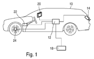
- FIG. 1 shows an overview drawing of the device for calibrating a Image sensor system 14 in conjunction with a motor vehicle 10 of the preferred Embodiment, consisting of a control unit 12 and an image sensor system 14th Furthermore, FIG. 1 shows an operating unit 18, a display unit 20 for displaying the Video image, a steering angle sensor 22 and a wheel angle sensor 24. The signals of the Steering angle sensor 22 and / or the signals of the wheel angle sensor 24 are for determination the driving tube used in reverse.
- the image sensor system 14, the control unit 18, the display unit 20, the steering angle sensor 22 and the wheel angle sensor 24 are over Signal lines connected to the controller 12. The transmission of the signals over the Signal lines are electrical and / or optical and / or radio.
- the signal lines are realized by a bus, for example the CAN bus.
- the image sensor system 14 is in the preferred embodiment, a CMOS camera with Wide-angle lens.
- the image sensor system is in the preferred embodiment in Rear area of the motor vehicle arranged such that the image sensor system detects at least part of the rear driving space of the motor vehicle.
- Figure 2 shows a plan view of the moving motor vehicle 10 of the preferred Embodiment illustrating the calibration of the image sensor system 14. Further shows Figure 2 is a flat roadway test field 26 on the road or the floor of a workshop.
- the Motor vehicle 10 is positioned at a first position 50 such that the roadway test field 26 is visible in the display unit 20 as image 36 of the roadway test field 26.
- the position of the image 36 of the roadway test field 26 interactively in the first position 50 as image measurements m1 determined by the auxiliary lines with be brought to the roadway test field to cover.
- the motor vehicle 10 moved forward to the second position 52.
- the signals of the steering angle sensor and / or the signals of the wheel speed sensor are detected and recorded and used to calibrate the image sensor system.
- the position of the image 36 of the roadway test field 26 interactively in the second position 52 is determined as image measurements m2.
- image measurements m1 and m2 and / or vehicle geometry data and / or vehicle movement data such as Signals of the steering angle sensor and / or the signals of the wheel speed sensor, and / or a Movement model of the motor vehicle 10.
- the sought installation parameters of the Image sensor system calculated in the control unit and for calibration of the image sensor system used.
- the device for calibration has at least one Image sensor system stored the geometric size of the roadway test field.
- the mounting angles, pitch angles and / or Yaw angle and / or roll angle determined.
- the Installation height of the image sensor system determined.
- the Installation height of the image sensor system determined.
- at least one intrinsic calibration parameter in a variant determined at least one intrinsic calibration parameter.
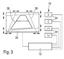
- FIG. 3 shows an input unit 18 of the apparatus for calibrating an image sensor system of the preferred embodiment, consisting of four cursor keys 34.
- the cursor keys 34 of the input unit 18 are connected via signal lines to the control unit 12 of the motor vehicle connected. Two of the cursor keys 34 serve for the horizontal movement of the auxiliary lines 38, while two other cursor keys 34 are used for the vertical movement of the auxiliary lines 38.
- the display unit 20 is connected to the control unit 12 via signal lines.
- the Transmission of the signals via the signal lines takes place electrically and / or optically and / or by radio. Alternatively or additionally, the signal lines are as a bus, for example a CAN bus, realized.
- the control unit 18 is only connected to the control unit 12 during manufacture and / or repair.
- the control unit 12 is installed in the motor vehicle and is part of the operation of the motor vehicle Rear view camera function. The same applies to the display unit 20, the regular Operation is also part of the rinsefahrmaschinefunktion.
- the input unit 18 includes a cursor beside the cursor keys 34 separate display unit and / or a separate control unit. Further, Figure 4 shows a video image on the display unit 20 comprising an image 36 of the roadway test field 26 and auxiliary lines 38.
- the location of the roadway test field at the first position and / or at the at least second position in the image automatically the controller is performed by image processing methods such as pattern recognition.
- Such a device designed Allows calibration of the image sensor system to any public street space present parking markings and / or lane markings. Alternatively or in addition will automatically recalibrate and / or monitor the decalibration at least part of the installation parameters during the intended use of the image sensor system.
- the device is configured accordingly.
- a further variant of the preferred embodiment provides that the device is configured so that the device, the image sensor system during the Proper use of the image sensor system as a function of Charging state of the motor vehicle initially calibrated and / or decalibration monitored and / or recalibrated. This will influence the operation of the image sensor system compensated for different loading conditions of the motor vehicle.
- the device is such configured that the device, the image sensor system during the intended Use of the image sensor system as a function of headlamp leveling of Headlamps of the motor vehicle calibrated and / or recalibrated.
- the preferred embodiment is in the movement of the Motor vehicle between the first position and the at least one second position of Steering of the motor vehicle between the right half steering angle and the right maximum steering angle and / or the steering angle of the motor vehicle between the left half steering angle and the left maximum steering angle.
- the steering angle of the motor vehicle maximum is in another Variant.
- the image sensor system alternatively or additionally a CCD camera.
- Image sensor system comprising at least two CCD cameras and / or CMOS cameras,
- the image sensor system is a stereo camera with two cameras in the essentially record the same scene.
Landscapes
- Engineering & Computer Science (AREA)
- Computer Vision & Pattern Recognition (AREA)
- Physics & Mathematics (AREA)
- General Physics & Mathematics (AREA)
- Theoretical Computer Science (AREA)
- Traffic Control Systems (AREA)
- Studio Devices (AREA)
- Closed-Circuit Television Systems (AREA)
- Image Processing (AREA)
- Radar Systems Or Details Thereof (AREA)
- Optical Radar Systems And Details Thereof (AREA)
Abstract
Description
- Figur 1 eine Übersichtszeichnung des bevorzugten Ausführungsbeispiels,
- Figur 2 eine Aufsicht des bewegten Kraftfahrzeuges des bevorzugten Ausführungsbeispiels,
- Figur 3 eine Eingabeeinheit der Vorrichtung zur Kalibrierung eines Bildsensorsystems des bevorzugten Ausführungsbeispiels.
- Der Nickwinkel und/oder der Gierwinkel und/oder der Wankwinkel zwischen Bildsensorsystem und Fahrbahn und/oder zwischen Bildsensorsystem und Fahrachse (Einbauwinkel), und/oder
- Die Höhe des Bildsensorsystems über der Fahrbahnebene, und/oder
- Der Abstand des Bildsensorsystems von der Hinterachse, und/oder
- die Querlage des Bildsensorsystems bezüglich der Kraftfahrzeuglängsebene.
Claims (11)
- Vorrichtung zur Kalibrierung wenigstens eines Bildsensorsystems, wobei die Vorrichtung derart konfiguriert ist, dass die Vorrichtung das in einem Kraftfahrzeug angeordnete Bildsensorsystem in Abhängigkeit von Bildsignalen des Bildsensorsystems von einem in einer Fahrbahnebene befindlichen Kalibrierobjekt kalibriert, dadurch gekennzeichnet, dass die Vorrichtung derart konfiguriert ist, dass die Vorrichtung das Bildsensorsystem in Abhängigkeit von einem ersten Bildsignal und wenigstens einem zweiten Bildsignal kalibriert, wobei das erste Bildsignal an einer ersten Position des Bildsensorsystems bezüglich des Kalibrierobjektes erzeugt wird und das zweite Bildsignal an wenigstens einer zweiten Position erzeugt wird, wobei die zweite Position von der ersten Position verschieden ist.
- Vorrichtung nach Anspruch 1, dadurch gekennzeichnet, dass das Bildsensorsystem zumindest einen Teil des rückwärtigen Fahrraumes des Kraftfahrzeuges erfasst.
- Vorrichtung nach einem der vorhergehenden Ansprüche, dadurch gekennzeichnet, dass das Kalibrierobjekt wenigstens eine zweidimensionale Markierung auf der Fahrbahnebene umfasst, wobei vorzugsweise die wenigstens eine Markierung in Form und Größe wenigstens eine Parkplatzmarkierung für Kraftfahrzeuge bildet.
- Vorrichtung nach einem der vorhergehenden Ansprüche, dadurch gekennzeichnet, dass die Vorrichtung derart konfiguriert ist, dass mittels Vorwärtsfahrt des Kraftfahrzeuges von der ersten Position des Bildsensorsystems die zweite Position des Bildsensorsystems eingenommen wird.
- Vorrichtung nach einem der vorhergehenden Ansprüche, dadurch gekennzeichnet, dass die Vorrichtung derart konfiguriert ist, dass mittels Rückwärtsfahrt des Kraftfahrzeuges von der ersten Position des Bildsensorsystems die zweite Position des Bildsensorsystems eingenommen wird.
- Vorrichtung nach einem der Ansprüche 4 oder 5, dadurch gekennzeichnet, dass der Lenkeinschlag des Kraftfahrzeuges zwischen dem rechten halben Lenkeinschlag und dem rechten maximalen Lenkeinschlag und/oder dass der Lenkeinschlag des Kraftfahrzeuges zwischen dem linken halben Lenkeinschlag und dem linken maximalen Lenkeinschlag ist, insbesondere dass der Lenkeinschlag des Kraftfahrzeuges maximal ist.
- Vorrichtung nach einem der vorhergehenden Ansprüche, dadurch gekennzeichnet, dass die Vorrichtung derart konfiguriert ist, dass die Vorrichtung das Bildsensorsystem in Abhängigkeit von Bildsignalen des Kalibrierobjektes kalibriert, wobei die Vorrichtung wenigstens ein geometrisches Merkmal des Kalibrierobjektes abgelegt hat.
- Vorrichtung nach einem der vorhergehenden Ansprüche, dadurch gekennzeichnet, dass die Vorrichtung derart konfiguriert ist, dass die Vorrichtung das Bildsensorsystem während der bestimmungsgemäßen Verwendung des Bildsensorsystems initial kalibriert und/oder eine Dekalibrierung überwacht und/oder nachkalibriert.
- Vorrichtung nach einem der vorhergehenden Ansprüche, dadurch gekennzeichnet, dass die Vorrichtung derart konfiguriert ist, dass die Vorrichtung das Bildsensorsystem während der bestimmungsgemäßen Verwendung des Bildsensorsystems in Abhängigkeit des Beladungszustandes des Kraftfahrzeuges initial kalibriert und/oder eine Dekalibrierung überwacht und/oder nachkalibriert.
- Vorrichtung nach einem der vorhergehenden Ansprüche, dadurch gekennzeichnet, dass die Vorrichtung derart konfiguriert ist, dass die Vorrichtung das Bildsensorsystem während der bestimmungsgemäßen Verwendung des Bildsensorsystems in Abhängigkeit einer Leuchtweitenregulierung von Scheinwerfern des Kraftfahrzeuges kalibriert und/oder nachkalibriert.
- Vorrichtung nach einem der vorhergehenden Ansprüche, dadurch gekennzeichnet, dass die Vorrichtung wenigstens eine Eingabeeinheit umfasst, wobei die Eingabeeinheit derart ausgestaltet ist, dass eine Kennzeichnung wenigstens eines Teils des Kalibrierobjektes in den Bildsignalen des Bildsensorsystems durchführbar ist.
Applications Claiming Priority (2)
| Application Number | Priority Date | Filing Date | Title |
|---|---|---|---|
| DE10360410 | 2003-12-19 | ||
| DE10360410A DE10360410A1 (de) | 2003-12-19 | 2003-12-19 | Vorrichtung zur Kalibrierung eines Bildsensorsystems |
Publications (3)
| Publication Number | Publication Date |
|---|---|
| EP1550982A2 true EP1550982A2 (de) | 2005-07-06 |
| EP1550982A3 EP1550982A3 (de) | 2010-04-28 |
| EP1550982B1 EP1550982B1 (de) | 2012-08-08 |
Family
ID=34559768
Family Applications (1)
| Application Number | Title | Priority Date | Filing Date |
|---|---|---|---|
| EP04105377A Expired - Lifetime EP1550982B1 (de) | 2003-12-19 | 2004-10-28 | Vorrichtung zur Kalibrierung eines Bildsensorsystems |
Country Status (2)
| Country | Link |
|---|---|
| EP (1) | EP1550982B1 (de) |
| DE (1) | DE10360410A1 (de) |
Cited By (1)
| Publication number | Priority date | Publication date | Assignee | Title |
|---|---|---|---|---|
| EP2523831B2 (de) † | 2010-01-13 | 2024-05-29 | Magna Electronics Inc. | Fahrzeugkamera und verfahren zur regelmässigen kalibrierung der fahrzeugkamera |
Family Cites Families (1)
| Publication number | Priority date | Publication date | Assignee | Title |
|---|---|---|---|---|
| US6813371B2 (en) * | 1999-12-24 | 2004-11-02 | Aisin Seiki Kabushiki Kaisha | On-vehicle camera calibration device |
-
2003
- 2003-12-19 DE DE10360410A patent/DE10360410A1/de not_active Withdrawn
-
2004
- 2004-10-28 EP EP04105377A patent/EP1550982B1/de not_active Expired - Lifetime
Cited By (1)
| Publication number | Priority date | Publication date | Assignee | Title |
|---|---|---|---|---|
| EP2523831B2 (de) † | 2010-01-13 | 2024-05-29 | Magna Electronics Inc. | Fahrzeugkamera und verfahren zur regelmässigen kalibrierung der fahrzeugkamera |
Also Published As
| Publication number | Publication date |
|---|---|
| DE10360410A1 (de) | 2005-07-14 |
| EP1550982B1 (de) | 2012-08-08 |
| EP1550982A3 (de) | 2010-04-28 |
Similar Documents
| Publication | Publication Date | Title |
|---|---|---|
| EP3586080B1 (de) | Vorrichtung und verfahren zum kalibrieren von fahrzeug-assistenz-systemen | |
| EP1376051B1 (de) | Kalibrierung eines Bildsensorsystems an einem Kraftfahrzeug mit Kalibrierobjekt und Lagebezugssensor | |
| DE10246066B4 (de) | Verfahren und Vorrichtung zur Kalibrierung eines Bildsensorsystems in einem Kraftfahrzeug | |
| EP1404545B1 (de) | Vorrichtung zur bilddetektion von gegenständen, personen oder dergleichen im umfeld eines fahrzeuges | |
| DE102010062696A1 (de) | Verfahren und Vorrichtung zum Kalibrieren und Justieren eines Fahrzeug-Umfeldsensors. | |
| EP2233365A2 (de) | Verfahren sowie Vorrichtung zum Bestimmen der Position und Ausrichtung einer Fahrerassistenzsystem-Kamera eines Fahrzeugs zu dem Fahrzeug | |
| DE102011075702A1 (de) | Verfahren und Vorrichtung zur Ausrichtung einer Projektion einer Projektionseinrichtung eines Fahrzeugs | |
| DE102017212289A1 (de) | Kalibriereinrichtung und Verfahren zum Kalibrieren von Kraftfahrzeug-Umfeldsensoren | |
| DE102017011177A1 (de) | Verfahren zum Ermitteln eines Knickwinkels eines Fahrzeug-Gespanns, Ermittlungseinrichtung sowie Fahrzeug-Gespann | |
| DE102018216104A1 (de) | Verfahren zum Kalibrieren eines Umfeldsensors eines Fahrzeugs mit Berücksichtigung eines dreidimensionalen Modells des Fahrzeugs, Kalibrierprüfstand sowie Fahrzeug | |
| EP1953520A2 (de) | Verfahren und Vorrichtung zum Ausrichten eines Fahrzeug-Umfeldsensors oder Scheinwerfers | |
| DE102017223098A1 (de) | Verfahren und Vorrichtung zur Ermittlung eines Relativwinkels zwischen zwei Fahrzeugen | |
| DE102010049216A1 (de) | Verfahren zum Betrieb einer an einem Fahrzeug angeordneten Kamera | |
| EP2131598A2 (de) | Stereokamerasystem und Verfahren zum Ermitteln mindestens eines Kalibrierfehlers eines Stereokamerasystems | |
| DE102015210816B4 (de) | Verfahren für einen Anhängerrangierassistenten | |
| EP2715666A1 (de) | Verfahren zum bestimmen einer nickbewegung einer in einem fahrzeug verbauten kamera und verfahren zur steuerung einer lichtaussendung zumindest eines frontscheinwerfers eines fahrzeugs | |
| DE102016208398B4 (de) | Verfahren zur Kalibrierung einer Fahrzeugkamera | |
| WO2018060344A1 (de) | Verkehrszeichenklassifikation in einem umgebungsbereich eines kraftfahrzeugs | |
| EP1550982B1 (de) | Vorrichtung zur Kalibrierung eines Bildsensorsystems | |
| EP1550983A1 (de) | Vorrichtung zur Kalibrierung eines Bildsensorsystems | |
| DE102016101359A1 (de) | Verfahren zum Verfahren zum Unterstützen eines Fahrers eines Kraftfahrzeugs bei einem Einparkvorgang in eine Parklücke mit Bordstein, Fahrerassistenzsystem sowie Kraftfahrzeug | |
| DE102021133091B4 (de) | Verfahren zur Ermittlung einer Ausrichtung einer Kameraeinheit einer Erfassungseinrichtung, Erfassungseinrichtung und Fahrzeug | |
| EP3032517A1 (de) | Vorrichtung und verfahren zur unterstützung eines fahrers eines fahrzeugs, insbesondere eines nutzfahrzeugs | |
| DE102024002115B4 (de) | Verfahren zur Erfassung von Bodenunebenheiten auf einer Straße sowie Erfassungssystem | |
| DE102020005136A1 (de) | Verfahren zum automatischen Steuern eines Fahrzeug-Anhänger-Gespanns mittels zwei Rückfahrkameras, sowie elektronisches Fahrzeuganhängerassistenzsystem |
Legal Events
| Date | Code | Title | Description |
|---|---|---|---|
| PUAI | Public reference made under article 153(3) epc to a published international application that has entered the european phase |
Free format text: ORIGINAL CODE: 0009012 |
|
| AK | Designated contracting states |
Kind code of ref document: A2 Designated state(s): AT BE BG CH CY CZ DE DK EE ES FI FR GB GR HU IE IT LI LU MC NL PL PT RO SE SI SK TR |
|
| AX | Request for extension of the european patent |
Extension state: AL HR LT LV MK |
|
| PUAL | Search report despatched |
Free format text: ORIGINAL CODE: 0009013 |
|
| AK | Designated contracting states |
Kind code of ref document: A3 Designated state(s): AT BE BG CH CY CZ DE DK EE ES FI FR GB GR HU IE IT LI LU MC NL PL PT RO SE SI SK TR |
|
| AX | Request for extension of the european patent |
Extension state: AL HR LT LV MK |
|
| 17P | Request for examination filed |
Effective date: 20101028 |
|
| 17Q | First examination report despatched |
Effective date: 20101122 |
|
| AKX | Designation fees paid |
Designated state(s): DE FR GB IT |
|
| GRAP | Despatch of communication of intention to grant a patent |
Free format text: ORIGINAL CODE: EPIDOSNIGR1 |
|
| GRAS | Grant fee paid |
Free format text: ORIGINAL CODE: EPIDOSNIGR3 |
|
| GRAA | (expected) grant |
Free format text: ORIGINAL CODE: 0009210 |
|
| AK | Designated contracting states |
Kind code of ref document: B1 Designated state(s): DE FR GB IT |
|
| REG | Reference to a national code |
Ref country code: GB Ref legal event code: FG4D Free format text: NOT ENGLISH |
|
| REG | Reference to a national code |
Ref country code: DE Ref legal event code: R096 Ref document number: 502004013673 Country of ref document: DE Effective date: 20121011 |
|
| PLBE | No opposition filed within time limit |
Free format text: ORIGINAL CODE: 0009261 |
|
| STAA | Information on the status of an ep patent application or granted ep patent |
Free format text: STATUS: NO OPPOSITION FILED WITHIN TIME LIMIT |
|
| 26N | No opposition filed |
Effective date: 20130510 |
|
| REG | Reference to a national code |
Ref country code: DE Ref legal event code: R097 Ref document number: 502004013673 Country of ref document: DE Effective date: 20130510 |
|
| PGFP | Annual fee paid to national office [announced via postgrant information from national office to epo] |
Ref country code: FR Payment date: 20141021 Year of fee payment: 11 Ref country code: GB Payment date: 20141024 Year of fee payment: 11 |
|
| PGFP | Annual fee paid to national office [announced via postgrant information from national office to epo] |
Ref country code: IT Payment date: 20141027 Year of fee payment: 11 |
|
| GBPC | Gb: european patent ceased through non-payment of renewal fee |
Effective date: 20151028 |
|
| PG25 | Lapsed in a contracting state [announced via postgrant information from national office to epo] |
Ref country code: IT Free format text: LAPSE BECAUSE OF NON-PAYMENT OF DUE FEES Effective date: 20151028 Ref country code: GB Free format text: LAPSE BECAUSE OF NON-PAYMENT OF DUE FEES Effective date: 20151028 |
|
| REG | Reference to a national code |
Ref country code: FR Ref legal event code: ST Effective date: 20160630 |
|
| PG25 | Lapsed in a contracting state [announced via postgrant information from national office to epo] |
Ref country code: FR Free format text: LAPSE BECAUSE OF NON-PAYMENT OF DUE FEES Effective date: 20151102 |
|
| PGFP | Annual fee paid to national office [announced via postgrant information from national office to epo] |
Ref country code: DE Payment date: 20221215 Year of fee payment: 19 |
|
| REG | Reference to a national code |
Ref country code: DE Ref legal event code: R119 Ref document number: 502004013673 Country of ref document: DE |
|
| PG25 | Lapsed in a contracting state [announced via postgrant information from national office to epo] |
Ref country code: DE Free format text: LAPSE BECAUSE OF NON-PAYMENT OF DUE FEES Effective date: 20240501 |