EP1550982A2 - Device for calibrating an image sensor system - Google Patents
Device for calibrating an image sensor system Download PDFInfo
- Publication number
- EP1550982A2 EP1550982A2 EP04105377A EP04105377A EP1550982A2 EP 1550982 A2 EP1550982 A2 EP 1550982A2 EP 04105377 A EP04105377 A EP 04105377A EP 04105377 A EP04105377 A EP 04105377A EP 1550982 A2 EP1550982 A2 EP 1550982A2
- Authority
- EP
- European Patent Office
- Prior art keywords
- sensor system
- image sensor
- motor vehicle
- image
- steering angle
- Prior art date
- Legal status (The legal status is an assumption and is not a legal conclusion. Google has not performed a legal analysis and makes no representation as to the accuracy of the status listed.)
- Granted
Links
Images

Classifications
-
- G—PHYSICS
- G06—COMPUTING OR CALCULATING; COUNTING
- G06T—IMAGE DATA PROCESSING OR GENERATION, IN GENERAL
- G06T7/00—Image analysis
- G06T7/80—Analysis of captured images to determine intrinsic or extrinsic camera parameters, i.e. camera calibration
Definitions
- the invention relates to a device for calibrating at least one image sensor system, wherein the image sensor system is arranged in a motor vehicle.
- a reversing camera system wherein a Camera with a wide-angle lens a video image of the situation behind a motor vehicle receives.
- the video image is presented in a display to the driver.
- guides in the video image are used for Visualization of the distance of the motor vehicle to obstacles or objects. Further show the guides depending on the steering wheel a driving tube in which move the motor vehicle at a backward movement with a constant steering angle would. This proposal has the advantage that the driver is easier to park.
- US 2001/0006554 A1 of 5 July 2001 discloses a device for calibrating a Camera of a motor vehicle, wherein for calibration a two-dimensional Calibration feature is mounted on the floor. After the motor vehicle in a is turned off predetermined position, the camera is calibrated by means of the calibration feature.
- the apparatus described below for calibrating at least one Image sensor system having the features of independent claim 1 has the advantage that an exact positioning of the motor vehicle with respect to the calibration object is not is required.
- Calibration objects are either expensive wheel alignment or roller dynamometers or Markings on the roadway required for positioning to determine the location of the road Specify rear axle, or the location of the calibration object is about additional technical Equipment in manufacturing or in workshops set. This is high cost connected, for example, the use of test benches, especially in manufacturing high Costs caused. Furthermore, test stands are not available in all workshops.
- the exact one Positioning of the motor vehicle by means of markings for positioning on the roadway is difficult as it depends on the skill of the driver. Also the use of additional technical equipment causes high costs.
- the hereinafter described device has the advantage of a precise, simple and at the same time cost-effective calibration of an image sensor system in a motor vehicle, in particular in a reversing camera system.
- the image sensor system at least a part of the rear Travel compartment of the motor vehicle detects, in particular, that the image sensor system component a rearview camera system is.
- the calibration object has at least one two-dimensional marking on the Fahrbahnebene includes, wherein preferably the at least one mark in the form and Size at least forms a parking mark for motor vehicles.
- the two-dimensional Marker is for example a road marking, such as an arrow, and / or a Park place marker.
- a road test field is of the simplest construction and therefore inexpensive.
- the level road test field is increasing in production and / or in a workshop little space, as it is passable and accessible.
- the two-dimensional marking as a thin plate and / or adhesive film and / or as Color application is realized because such a mark inexpensive, resistant to aging and is resistant.
- parking markings Parking space markings
- a further advantage is that the device is configured such that by means of forward travel and / or reversing the motor vehicle from the first position of the image sensor system second position of the image sensor system is taken.
- the configuration of the device in the forward drive has the advantage that the device, the image sensor system in the Can calibrate the majority of operating time, since the forward drive is the most common mode of operation Motor vehicle is.
- the steering angle of the motor vehicle between the right half Steering angle and the right maximum steering angle and / or the steering angle of the Motor vehicle between the left half steering angle and the left maximum Steering lock is.
- the steering angle of the motor vehicle maximum This increases the accuracy of the calibration. At the same time it goes in advantageously an increase in the accuracy of the representation of the driving tube associated.
- the device is configured such that the device the Image sensor system calibrated in dependence on image signals of the calibration object, wherein the Device has stored at least one geometric feature of the calibration object.
- One geometric feature is, for example, the length and / or width of a Road markings and / or a parking mark.
- Such a device has the Advantage that the accuracy of the calibration is increased.
- Particularly advantageous is a Such calibration and thus such a device in the automotive production and / or in motor vehicle workshops.
- This has the advantage of having any parking mark and / or lane marking of the public traffic area for the determination of Installation parameter can be used.
- the device is configured such that the device is the Image sensor system during the intended use of the image sensor system initial, ie first or new, calibrated and / or a decalibration monitored and / or recalibrated. This allows a continuous monitoring of the functionality of the Image sensor system.
- the device comprises at least one input unit, wherein the input unit is designed such that an identification of at least part of the Kalibrier Anlagenes in the image signals of the image sensor system is feasible.
- the input unit is designed such that an identification of at least part of the Kalibrier Consumes in the image signals of the image sensor system is feasible.
- the device is configured such that the device in a Motor vehicle arranged image sensor system in response to image signals of the Image sensor system of a located in a road plane calibration object calibrated. Furthermore, the device is configured such that the device stores the Image sensor system in response to a first image signal and at least one calibrated second image signal, wherein the first image signal at a first position of the Image sensor system is generated with respect to the calibration object and the second Image signal is generated at at least a second position, wherein the second position different from the first position.
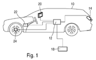
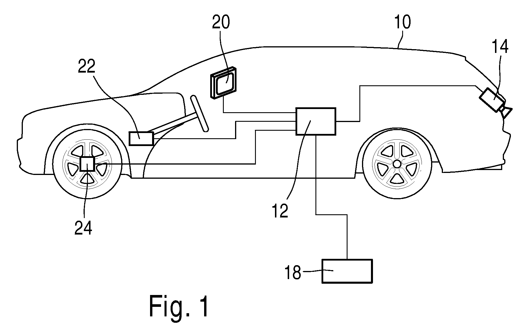
- FIG. 1 shows an overview drawing of the device for calibrating a Image sensor system 14 in conjunction with a motor vehicle 10 of the preferred Embodiment, consisting of a control unit 12 and an image sensor system 14th Furthermore, FIG. 1 shows an operating unit 18, a display unit 20 for displaying the Video image, a steering angle sensor 22 and a wheel angle sensor 24. The signals of the Steering angle sensor 22 and / or the signals of the wheel angle sensor 24 are for determination the driving tube used in reverse.
- the image sensor system 14, the control unit 18, the display unit 20, the steering angle sensor 22 and the wheel angle sensor 24 are over Signal lines connected to the controller 12. The transmission of the signals over the Signal lines are electrical and / or optical and / or radio.
- the signal lines are realized by a bus, for example the CAN bus.
- the image sensor system 14 is in the preferred embodiment, a CMOS camera with Wide-angle lens.
- the image sensor system is in the preferred embodiment in Rear area of the motor vehicle arranged such that the image sensor system detects at least part of the rear driving space of the motor vehicle.
- Figure 2 shows a plan view of the moving motor vehicle 10 of the preferred Embodiment illustrating the calibration of the image sensor system 14. Further shows Figure 2 is a flat roadway test field 26 on the road or the floor of a workshop.
- the Motor vehicle 10 is positioned at a first position 50 such that the roadway test field 26 is visible in the display unit 20 as image 36 of the roadway test field 26.
- the position of the image 36 of the roadway test field 26 interactively in the first position 50 as image measurements m1 determined by the auxiliary lines with be brought to the roadway test field to cover.
- the motor vehicle 10 moved forward to the second position 52.
- the signals of the steering angle sensor and / or the signals of the wheel speed sensor are detected and recorded and used to calibrate the image sensor system.
- the position of the image 36 of the roadway test field 26 interactively in the second position 52 is determined as image measurements m2.
- image measurements m1 and m2 and / or vehicle geometry data and / or vehicle movement data such as Signals of the steering angle sensor and / or the signals of the wheel speed sensor, and / or a Movement model of the motor vehicle 10.
- the sought installation parameters of the Image sensor system calculated in the control unit and for calibration of the image sensor system used.
- the device for calibration has at least one Image sensor system stored the geometric size of the roadway test field.
- the mounting angles, pitch angles and / or Yaw angle and / or roll angle determined.
- the Installation height of the image sensor system determined.
- the Installation height of the image sensor system determined.
- at least one intrinsic calibration parameter in a variant determined at least one intrinsic calibration parameter.
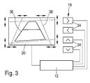
- FIG. 3 shows an input unit 18 of the apparatus for calibrating an image sensor system of the preferred embodiment, consisting of four cursor keys 34.
- the cursor keys 34 of the input unit 18 are connected via signal lines to the control unit 12 of the motor vehicle connected. Two of the cursor keys 34 serve for the horizontal movement of the auxiliary lines 38, while two other cursor keys 34 are used for the vertical movement of the auxiliary lines 38.
- the display unit 20 is connected to the control unit 12 via signal lines.
- the Transmission of the signals via the signal lines takes place electrically and / or optically and / or by radio. Alternatively or additionally, the signal lines are as a bus, for example a CAN bus, realized.
- the control unit 18 is only connected to the control unit 12 during manufacture and / or repair.
- the control unit 12 is installed in the motor vehicle and is part of the operation of the motor vehicle Rear view camera function. The same applies to the display unit 20, the regular Operation is also part of the rinsefahrmaschinefunktion.
- the input unit 18 includes a cursor beside the cursor keys 34 separate display unit and / or a separate control unit. Further, Figure 4 shows a video image on the display unit 20 comprising an image 36 of the roadway test field 26 and auxiliary lines 38.
- the location of the roadway test field at the first position and / or at the at least second position in the image automatically the controller is performed by image processing methods such as pattern recognition.
- Such a device designed Allows calibration of the image sensor system to any public street space present parking markings and / or lane markings. Alternatively or in addition will automatically recalibrate and / or monitor the decalibration at least part of the installation parameters during the intended use of the image sensor system.
- the device is configured accordingly.
- a further variant of the preferred embodiment provides that the device is configured so that the device, the image sensor system during the Proper use of the image sensor system as a function of Charging state of the motor vehicle initially calibrated and / or decalibration monitored and / or recalibrated. This will influence the operation of the image sensor system compensated for different loading conditions of the motor vehicle.
- the device is such configured that the device, the image sensor system during the intended Use of the image sensor system as a function of headlamp leveling of Headlamps of the motor vehicle calibrated and / or recalibrated.
- the preferred embodiment is in the movement of the Motor vehicle between the first position and the at least one second position of Steering of the motor vehicle between the right half steering angle and the right maximum steering angle and / or the steering angle of the motor vehicle between the left half steering angle and the left maximum steering angle.
- the steering angle of the motor vehicle maximum is in another Variant.
- the image sensor system alternatively or additionally a CCD camera.
- Image sensor system comprising at least two CCD cameras and / or CMOS cameras,
- the image sensor system is a stereo camera with two cameras in the essentially record the same scene.
Landscapes
- Engineering & Computer Science (AREA)
- Computer Vision & Pattern Recognition (AREA)
- Physics & Mathematics (AREA)
- General Physics & Mathematics (AREA)
- Theoretical Computer Science (AREA)
- Traffic Control Systems (AREA)
- Studio Devices (AREA)
- Closed-Circuit Television Systems (AREA)
- Image Processing (AREA)
- Radar Systems Or Details Thereof (AREA)
- Optical Radar Systems And Details Thereof (AREA)
Abstract
Es wird eine Vorrichtung zur Kalibrierung wenigstens eines Bildsensorsystems
vorgeschlagen. Die Vorrichtung ist derart konfiguriert, dass die Vorrichtung das in einem
Kraftfahrzeug angeordnete Bildsensorsystem in Abhängigkeit von Bildsignalen des
Bildsensorsystems von einem in einer Fahrbahnebene befindlichen Kalibrierobjekt
kalibriert. Ferner ist die Vorrichtung derart konfiguriert, dass die Vorrichtung das
Bildsensorsystem in Abhängigkeit von einem ersten Bildsignal und wenigstens einem
zweiten Bildsignal kalibriert, wobei das erste Bildsignal an einer ersten Position des
Bildsensorsystems bezüglich des Kalibrierobjektes erzeugt wird und das zweite
Bildsignal an wenigstens einer zweiten Position erzeugt wird, wobei die zweite Position
von der ersten Position verschieden ist.
Description
Die Erfindung betrifft eine Vorrichtung zur Kalibrierung wenigstens eines Bildsensorsystems, wobei das Bildsensorsystem in einem Kraftfahrzeug angeordnet ist.The invention relates to a device for calibrating at least one image sensor system, wherein the image sensor system is arranged in a motor vehicle.
Kraftfahrzeughersteller planen den Einsatz von Kameras in Kraftfahrzeugen, beispielsweise von Rückfahrkameras.Motor vehicle manufacturers plan the use of cameras in motor vehicles, for example of Reversing cameras.
Beispielsweise ist aus der WO 00/74976 A1 ein Rückfahrkamerasystem bekannt, wobei eine Kamera mit einer Weitwinkeloptik ein Videobild von der Situation hinter einem Kraftfahrzeug aufnimmt. Das Videobild wird in einem Display dem Fahrer präsentiert. Zusätzlich wird vorgeschlagen, Hilfslinien in das Videobild einzuzeichnen. Die Hilfslinien dienen zur Visualisierung des Abstandes des Kraftfahrzeuges zu Hindernissen oder Objekten. Ferner zeigen die Hilfslinien in Abhängigkeit vom Lenkradeinschlag einen Fahrschlauch in dem sich das Kraftfahrzeug bei einer Rückwärtsbewegung mit konstantem Lenkwinkeleinschlag bewegen würde. Dieser Vorschlag hat den Vorteil, dass dem Fahrer das Einparken erleichtert wird.For example, from WO 00/74976 A1 a reversing camera system is known, wherein a Camera with a wide-angle lens a video image of the situation behind a motor vehicle receives. The video image is presented in a display to the driver. In addition will proposed to draw guides in the video image. The guides are used for Visualization of the distance of the motor vehicle to obstacles or objects. Further show the guides depending on the steering wheel a driving tube in which move the motor vehicle at a backward movement with a constant steering angle would. This proposal has the advantage that the driver is easier to park.
Die US 2001/0006554 A1 vom 5. Juli 2001 offenbart eine Vorrichtung zur Kalibrierung einer Kamera eines Kraftfahrzeuges, wobei zur Kalibrierung ein zweidimensionales Kalibriermerkmal auf dem Boden angebracht ist. Nachdem das Kraftfahrzeug in einer vorbestimmten Position abgestellt ist, wird die Kamera mittels des Kalibriermerkmals kalibriert.US 2001/0006554 A1 of 5 July 2001 discloses a device for calibrating a Camera of a motor vehicle, wherein for calibration a two-dimensional Calibration feature is mounted on the floor. After the motor vehicle in a is turned off predetermined position, the camera is calibrated by means of the calibration feature.
Die nachfolgend beschriebene Vorrichtung zur Kalibrierung wenigstens eines Bildsensorsystems mit den Merkmalen des unabhängigen Patentanspruchs 1 hat den Vorteil, dass eine exakte Positionierung des Kraftfahrzeuges bezüglich des Kalibrierobjektes nicht erforderlich ist. Für eine exakte Positionierung des Kraftfahrzeuges bezüglich eines Kalibrierobjektes sind entweder teure Achsmessstände oder Rollenprüfstände oder Markierungen auf der Fahrbahn für die Positionierung erforderlich, um die Lage der Hinterachse festzulegen, oder die Lage des Kalibrierobjektes wird über zusätzliche technische Ausrüstungen in der Fertigung oder in Werkstätten festgelegt. Dies ist mit hohen Kosten verbunden, da beispielsweise die Nutzung von Prüfständen insbesondere in der Fertigung hohe Kosten verursacht. Ferner sind Prüfstände nicht in allen Werkstätten vorhanden. Die exakte Positionierung des Kraftfahrzeuges mittels Markierungen zur Positionierung auf der Fahrbahn ist schwierig, da dies vom Geschick des Fahrers abhängt. Auch die Verwendung von zusätzlicher technischer Ausrüstung verursacht hohe Kosten. Zusammenfassend hat die nachfolgend beschriebene Vorrichtung den Vorteil einer exakten, einfachen und zugleich kostengünstigen Kalibrierung eines Bildsensorsystems in einem Kraftfahrzeug, insbesondere in einem Rückfahrkamerasystem.The apparatus described below for calibrating at least one Image sensor system having the features of independent claim 1 has the advantage that an exact positioning of the motor vehicle with respect to the calibration object is not is required. For an exact positioning of the motor vehicle with respect to a Calibration objects are either expensive wheel alignment or roller dynamometers or Markings on the roadway required for positioning to determine the location of the road Specify rear axle, or the location of the calibration object is about additional technical Equipment in manufacturing or in workshops set. This is high cost connected, for example, the use of test benches, especially in manufacturing high Costs caused. Furthermore, test stands are not available in all workshops. The exact one Positioning of the motor vehicle by means of markings for positioning on the roadway is difficult as it depends on the skill of the driver. Also the use of additional technical equipment causes high costs. In summary, the hereinafter described device has the advantage of a precise, simple and at the same time cost-effective calibration of an image sensor system in a motor vehicle, in particular in a reversing camera system.
Besonders vorteilhaft ist, dass das Bildsensorsystem zumindest einen Teil des rückwärtigen Fahrraumes des Kraftfahrzeuges erfasst, insbesondere, dass das Bildsensorsystem Bestandteil eines Rückfahrkamerasystems ist.It is particularly advantageous that the image sensor system at least a part of the rear Travel compartment of the motor vehicle detects, in particular, that the image sensor system component a rearview camera system is.
Vorteilhaft ist, dass das Kalibrierobjekt wenigstens eine zweidimensionale Markierung auf der Fahrbahnebene umfasst, wobei vorzugsweise die wenigstens eine Markierung in Form und Größe wenigstens eine Parkplatzmarkierung für Kraftfahrzeuge bildet. Die zweidimensionale Markierung ist beispielsweise eine Fahrbahnmarkierung, beispielsweise ein Pfeil, und/oder eine Parkplatzmarkierung. Ein solches Fahrbahntestfeld ist von einfachstem Aufbau und daher kostengünstig. Das ebene Fahrbahntestfeld nimmt in der Fertigung und/oder einer Werkstatt wenig Platz in Anspruch, da es überfahrbar und begehbar ist. Vorteilhaft ist hierbei, wenn die zweidimensionale Markierung als dünne Platte und/oder aufklebbare Folie und/oder als Farbauftrag realisiert ist, da eine derartige Markierung kostengünstig, alterungsbeständig und widerstandsfähig ist. Besonders vorteilhaft ist der Einsatz von Parkplatzmarkierungen (Parklückenmarkierungen), da diese im urbanen Umfeld vorhanden sind und hierdurch eine Unabhängigkeit von Werkstätten und speziellen Ausrüstungen erreicht wird. It is advantageous that the calibration object has at least one two-dimensional marking on the Fahrbahnebene includes, wherein preferably the at least one mark in the form and Size at least forms a parking mark for motor vehicles. The two-dimensional Marker is for example a road marking, such as an arrow, and / or a Park place marker. Such a road test field is of the simplest construction and therefore inexpensive. The level road test field is increasing in production and / or in a workshop little space, as it is passable and accessible. It is advantageous if the two-dimensional marking as a thin plate and / or adhesive film and / or as Color application is realized because such a mark inexpensive, resistant to aging and is resistant. Particularly advantageous is the use of parking markings (Parking space markings), since these are present in the urban environment and thus one Independence of workshops and special equipment is achieved.
Ein weiterer Vorteil ist, dass die Vorrichtung derart konfiguriert ist, dass mittels Vorwärtsfahrt und/oder Rückwärtsfahrt des Kraftfahrzeuges von der ersten Position des Bildsensorsystems die zweite Position des Bildsensorsystems eingenommen wird. Die Konfiguration der Vorrichtung in der Vorwärtsfahrt hat den Vorteil, dass die Vorrichtung das Bildsensorsystem in der Mehrzahl der Betriebszeit kalibrieren kann, da die Vorwärtsfahrt die häufigste Betriebsart des Kraftfahrzeuges ist.A further advantage is that the device is configured such that by means of forward travel and / or reversing the motor vehicle from the first position of the image sensor system second position of the image sensor system is taken. The configuration of the device in the forward drive has the advantage that the device, the image sensor system in the Can calibrate the majority of operating time, since the forward drive is the most common mode of operation Motor vehicle is.
Vorteilhaft ist, dass der Lenkeinschlag des Kraftfahrzeuges zwischen dem rechten halben Lenkeinschlag und dem rechten maximalen Lenkeinschlag und/oder der Lenkeinschlag des Kraftfahrzeuges zwischen dem linken halben Lenkeinschlag und dem linken maximalen Lenkeinschlag ist. In einer weiteren Variante ist der Lenkeinschlag des Kraftfahrzeuges maximal. Hierdurch wird die Genauigkeit der Kalibrierung erhöht. Gleichzeitig geht damit in vorteilhafter Weise eine Erhöhung der Genauigkeit der Darstellung des Fahrschlauches einher.It is advantageous that the steering angle of the motor vehicle between the right half Steering angle and the right maximum steering angle and / or the steering angle of the Motor vehicle between the left half steering angle and the left maximum Steering lock is. In a further variant, the steering angle of the motor vehicle maximum. This increases the accuracy of the calibration. At the same time it goes in advantageously an increase in the accuracy of the representation of the driving tube associated.
Besonders vorteilhaft ist, dass die Vorrichtung derart konfiguriert ist, dass die Vorrichtung das Bildsensorsystem in Abhängigkeit von Bildsignalen des Kalibrierobjektes kalibriert, wobei die Vorrichtung wenigstens ein geometrisches Merkmal des Kalibrierobjektes abgelegt hat. Ein geometrisches Merkmal ist dabei beispielsweise die Länge und/oder Breite einer Fahrbahnmarkierung und/oder einer Parkplatzmarkierung. Eine derartige Vorrichtung hat den Vorteil, dass die Genauigkeit der Kalibrierung erhöht wird. Besonders vorteilhaft ist eine derartige Kalibrierung und damit eine derartige Vorrichtung in der Kraftfahrzeugfertigung und/oder in Kraftfahrzeugwerkstätten. Ferner ist es vorteilhaft, bei nicht bekannten geometrischen Merkmalen einer Fahrbahnmarkierung, beispielsweise der 3-dimensionalen Größe, die Bildsignale des Bildsensorsystems mit Signalen von Raddrehzahlsensoren und/oder Lenkwinkelsensoren gemeinsam auszuwerten, da dies die Bestimmung der Einbauparameter des Bildsensorsystems erlaubt. Dies hat den Vorteil, dass eine beliebige Parkplatzmarkierung und/oder Fahrbahnmarkierung des öffentlichen Verkehrsraumes zur Bestimmung der Einbauparameter einsetzbar ist.It is particularly advantageous that the device is configured such that the device the Image sensor system calibrated in dependence on image signals of the calibration object, wherein the Device has stored at least one geometric feature of the calibration object. One geometric feature is, for example, the length and / or width of a Road markings and / or a parking mark. Such a device has the Advantage that the accuracy of the calibration is increased. Particularly advantageous is a Such calibration and thus such a device in the automotive production and / or in motor vehicle workshops. Furthermore, it is advantageous in unknown geometric features of a lane marking, such as the 3-dimensional Size, the image signals of the image sensor system with signals from wheel speed sensors and / or To evaluate steering angle sensors together, as this is the determination of the installation parameters of the Image sensor system allowed. This has the advantage of having any parking mark and / or lane marking of the public traffic area for the determination of Installation parameter can be used.
Vorteilhaft ist, dass die Vorrichtung derart konfiguriert ist, dass die Vorrichtung das Bildsensorsystem während der bestimmungsgemäßen Verwendung des Bildsensorsystems initial, also erstmalig oder neu, kalibriert und/oder eine Dekalibrierung überwacht und/oder nachkalibriert. Dies ermöglicht eine fortwährende Überwachung der Funktionsfähigkeit des Bildsensorsystems.It is advantageous that the device is configured such that the device is the Image sensor system during the intended use of the image sensor system initial, ie first or new, calibrated and / or a decalibration monitored and / or recalibrated. This allows a continuous monitoring of the functionality of the Image sensor system.
Besonders vorteilhaft ist, dass die Vorrichtung wenigstens eine Eingabeeinheit umfasst, wobei die Eingabeeinheit derart ausgestaltet ist, dass eine Kennzeichnung wenigstens eines Teils des Kalibrierobjektes in den Bildsignalen des Bildsensorsystems durchführbar ist. Dies ermöglicht die manuelle Positionierung von Hilfslinien im angezeigten Videobild (Displaybild) beispielsweise mittels Cursor-Tasten, so dass die Hilfslinien mit dem erfassten Videobild zur Deckung kommen. Diese manuell von einem Bediener durchgeführte Messung ist einfach und robust. Alternativ oder zusätzlich wird eine automatische Auswertung durchgeführt. Obwohl hierzu aufwendige Algorithmen zur Bildverarbeitung erforderlich sind und dies zu einer höheren Rechenleistung im Steuergerät führt, bietet die automatische Auswertung den Vorteil, dass keine Bedienereingaben erforderlich sind.It is particularly advantageous that the device comprises at least one input unit, wherein the input unit is designed such that an identification of at least part of the Kalibrierobjektes in the image signals of the image sensor system is feasible. this makes possible Manual positioning of guides in the displayed video image (display image) for example by means of cursor keys, so that the auxiliary lines with the captured video image for Cover come. This manual measurement by an operator is simple and easy robust. Alternatively or additionally, an automatic evaluation is performed. Even though this complex algorithms are required for image processing and this to a higher computing power in the control unit, the automatic evaluation offers the advantage that no operator input is required.
Weitere Vorteile ergeben sich aus der nachfolgenden Beschreibung von Ausführungsbeispielen mit Bezug auf die Figuren und aus den abhängigen Patentansprüchen.Further advantages will become apparent from the following description of exemplary embodiments with reference to the figures and from the dependent claims.
Die Erfindung wird nachstehend anhand der in der Zeichnung dargestellten Ausführungsformen näher erläutert.The invention will be described below with reference to the embodiments shown in the drawing explained in more detail.
Es zeigen:
- Figur 1 eine Übersichtszeichnung des bevorzugten Ausführungsbeispiels,
- Figur 2 eine Aufsicht des bewegten Kraftfahrzeuges des bevorzugten Ausführungsbeispiels,
- Figur 3 eine Eingabeeinheit der Vorrichtung zur Kalibrierung eines Bildsensorsystems des bevorzugten Ausführungsbeispiels.
- FIG. 1 is an overview drawing of the preferred embodiment,
- FIG. 2 is a plan view of the moving motor vehicle of the preferred embodiment;
- 3 shows an input unit of the apparatus for calibrating an image sensor system of the preferred embodiment.
Nachfolgend wird eine Vorrichtung zur Kalibrierung wenigstens eines Bildsensorsystems beschrieben. Die Vorrichtung ist derart konfiguriert, dass die Vorrichtung das in einem Kraftfahrzeug angeordnete Bildsensorsystem in Abhängigkeit von Bildsignalen des Bildsensorsystems von einem in einer Fahrbahnebene befindlichen Kalibrierobjekt kalibriert. Ferner ist die Vorrichtung derart konfiguriert, dass die Vorrichtung das Bildsensorsystem in Abhängigkeit von einem ersten Bildsignal und wenigstens einem zweiten Bildsignal kalibriert, wobei das erste Bildsignal an einer ersten Position des Bildsensorsystems bezüglich des Kalibrierobjektes erzeugt wird und das zweite Bildsignal an wenigstens einer zweiten Position erzeugt wird, wobei die zweite Position von der ersten Position verschieden ist.A device for calibrating at least one image sensor system will be described below described. The device is configured such that the device in a Motor vehicle arranged image sensor system in response to image signals of the Image sensor system of a located in a road plane calibration object calibrated. Furthermore, the device is configured such that the device stores the Image sensor system in response to a first image signal and at least one calibrated second image signal, wherein the first image signal at a first position of the Image sensor system is generated with respect to the calibration object and the second Image signal is generated at at least a second position, wherein the second position different from the first position.
Das System der Rückfahrkamera beinhaltet wenigstens ein Bildsensorsystem, das im Kraftfahrzeug angeordnet ist und zumindest einen Teil des rückwärtigen Fahrraumes des Kraftfahrzeuges erfasst, und eine Anzeigeeinheit zur Bildwiedergabe des erfassten Fahrraumes. Die geometrisch exakte Einblendung von Hilfslinien in das Videobild erfordert eine Kalibrierung des Bildsensorsystems. Diese Kalibrierung umfasst die Bestimmung von intrinsischen Kalibrierparametem, insbesondere die Beschreibung der Abbildung in dem Bildsensorsystem, und/oder von extrinsischen Kalibrierparametem (Parameter der Einbaukalibrierung, Einbauparameter), welche die Lage des Bildsensorsystems bezüglich des Kraftfahrzeuges bzw. der Fahrbahnebene beschreiben. Für die Darstellung eines Fahrschlauches ist weiterhin eine Auswertung der Lenkwinkelsignale und deren Umrechnung in Bewegungstrajektorien des Kraftfahrzeuges erforderlich. Die Einblendung von Linien im Videobild, welche die Entfernung zu Hindernissen visualisieren, nachfolgend als Entfernungslinien bezeichnet, ermöglichen dem Fahrer die Entfernung zu Hindernissen hinter dem Kraftfahrzeug abzuschätzen. Die Parameter der Einbaukalibrierung des Systems Rückfahrkamera, die nach Montage des Bildsensorsystems im Kraftfahrzeug zum Teil für jedes Kraftfahrzeug individuell ermittelt werden müssen, sind:
- Der Nickwinkel und/oder der Gierwinkel und/oder der Wankwinkel zwischen Bildsensorsystem und Fahrbahn und/oder zwischen Bildsensorsystem und Fahrachse (Einbauwinkel), und/oder
- Die Höhe des Bildsensorsystems über der Fahrbahnebene, und/oder
- Der Abstand des Bildsensorsystems von der Hinterachse, und/oder
- die Querlage des Bildsensorsystems bezüglich der Kraftfahrzeuglängsebene.
- The pitch angle and / or the yaw angle and / or the roll angle between the image sensor system and the road surface and / or between the image sensor system and the driving axis (installation angle), and / or
- The height of the image sensor system above the road level, and / or
- The distance of the image sensor system from the rear axle, and / or
- the transverse position of the image sensor system with respect to the vehicle longitudinal plane.
Figur 1 zeigt eine Übersichtszeichnung der Vorrichtung zur Kalibrierung eines
Bildsensorsystems 14 in Verbindung mit einem Kraftfahrzeug 10 des bevorzugten
Ausführungsbeispiels, bestehend aus einem Steuergerät 12 und einem Bildsensorsystem 14.
Ferner zeigt Figur 1 eine Bedieneinheit 18, eine Anzeigeeinheit 20 zur Darstellung des
Videobildes, einen Lenkwinkelsensor 22 und einen Radwinkelsensor 24. Die Signale des
Lenkwinkelsensors 22 und/oder die Signale des Radwinkelsensors 24 werden zur Bestimmung
des Fahrschlauches bei Rückwärtsfahrt eingesetzt. Das Bildsensorsystem 14, die Bedieneinheit
18, die Anzeigeeinheit 20, der Lenkwinkelsensor 22 und der Radwinkelsensor 24 sind über
Signalleitungen mit dem Steuergerät 12 verbunden. Die Übertragung der Signale über die
Signalleitungen erfolgt elektrisch und/oder optisch und/oder per Funk. Alternativ oder
zusätzlich sind die Signalleitungen durch einen Bus, beispielsweise dem CAN-Bus, realisiert.
Das Bildsensorsystem 14 ist im bevorzugten Ausführungsbeispiel eine CMOS-Kamera mit
Weitwinkeloptik. Das Bildsensorsystem ist im bevorzugten Ausführungsbeispiel im
rückwärtigen Bereich des Kraftfahrzeuges derart angeordnet, dass das Bildsensorsystem
zumindest einen Teil des rückwärtigen Fahrraumes des Kraftfahrzeuges erfasst.FIG. 1 shows an overview drawing of the device for calibrating a
Figur 2 zeigt eine Aufsicht des bewegten Kraftfahrzeuges 10 des bevorzugten
Ausführungsbeispiels zur Illustrierung der Kalibrierung des Bildsensorsystems 14. Ferner zeigt
Figur 2 ein ebenes Fahrbahntestfeld 26 auf der Fahrbahn bzw. dem Boden einer Werkstatt. Das
Kraftfahrzeug 10 wird an einer ersten Position 50 derart positioniert, dass das Fahrbahntestfeld
26 in der Anzeigeeinheit 20 als Bild 36 des Fahrbahntestfeldes 26 sichtbar ist. Mittels der in
Figur 3 dargestellten Eingabeeinheit wird die Lage des Bildes 36 des Fahrbahntestfeldes 26
interaktiv in der ersten Position 50 als Bildmessungen m1 bestimmt, indem die Hilfslinien mit
dem Fahrbahntestfeld zur Deckung gebracht werden. Anschließend wird das Kraftfahrzeug 10
durch Vorwärtsfahrt in die zweite Position 52 bewegt. Im bevorzugten Ausführungsbeispiel
werden die Signale des Lenkwinkelsensors und/oder die Signale des Raddrehzahlsensors erfasst
und aufgezeichnet und zur Kalibrierung des Bildsensorsystems eingesetzt. Mittels der in Figur 3
dargestellten Eingabeeinheit wird die Lage des Bildes 36 des Fahrbahntestfeldes 26 interaktiv in
der zweiten Position 52 als Bildmessungen m2 bestimmt. Aus den Bildmessungen m1 und m2
und/oder den Daten zur Fahrzeuggeometrie und/oder den Daten zur Fahrzeugbewegung, wie die
Signale des Lenkwinkelsensors und/oder den Signalen des Raddrehzahlsensors, und/oder einem
Bewegungsmodell des Kraftfahrzeuges 10 werden die gesuchten Einbauparameter des
Bildsensorsystems im Steuergerät berechnet und zur Kalibrierung des Bildsensorsystems
verwendet. Alternativ oder zusätzlich werden die Einbauparameter für die Darstellung von
Abstandslinien und/oder eines Fahrschlauches in Anzeigeeinheit (Display) verwendet. Im
bevorzugten Ausführungsbeispiel hat die Vorrichtung zur Kalibrierung wenigstens eines
Bildsensorsystems die geometrische Größe des Fahrbahntestfeldes abgelegt. Basierend auf den
Bilddaten an zwei unterschiedlichen Positionen werden die Einbauwinkel, Nickwinkel und/oder
Gierwinkel und/oder Wankwinkel, bestimmt. Bei vorhanden Signalen aus den
Raddrehzahlsensoren und/oder Signalen aus den Lenkwinkelsensoren wird zusätzlich die
Einbauhöhe des Bildsensorsystems bestimmt. Alternativ oder zusätzlich wird in einer Variante
wenigstens ein intrinsischer Kalibrierparameter ermittelt.Figure 2 shows a plan view of the moving
Figur 3 zeigt eine Eingabeeinheit 18 der Vorrichtung zur Kalibrierung eines Bildsensorsystems
des bevorzugten Ausführungsbeispiels, bestehend aus vier Cursor-Tasten 34. Die Cursor-Tasten
34 der Eingabeeinheit 18 sind über Signalleitungen mit dem Steuergerät 12 des Kraftfahrzeuges
verbunden. Zwei der Cursor-Tasten 34 dienen zur horizontalen Bewegung der Hilfslinien 38,
während zwei weitere Cursor-Tasten 34 zur vertikalen Bewegung der Hilfslinien 38 dienen.
Ferner ist die Anzeigeeinheit 20 über Signalleitungen mit dem Steuergerät 12 verbunden. Die
Übertragung der Signale über die Signalleitungen erfolgt elektrisch und/oder optisch und/oder
per Funk. Alternativ oder zusätzlich sind die Signalleitungen als Bus, beispielsweise einem
CAN-Bus, realisiert. Im bevorzugten Ausführungsbeispiel wird die Bedieneinheit 18 lediglich
bei der Fertigung und/oder Reparatur an die Steuereinheit 12 angeschlossen. Die Steuereinheit
12 ist im Kraftfahrzeug installiert und ist im Betrieb des Kraftfahrzeuges Bestandteil der
Rückfahrkamerafunktion. Entsprechendes gilt für die Anzeigeeinheit 20, die im regulären
Betrieb ebenfalls Bestandteil der Rückfahrkamerafunktion ist. In einer Variante des bevorzugten
Ausführungsbeispiels beinhaltet die Eingabeeinheit 18 neben den Cursor-Tasten 34 eine
separate Anzeigeeinheit und/oder eine separate Steuereinheit. Ferner zeigt Figur 4 ein Videobild
auf der Anzeigeeinheit 20 umfassend ein Bild 36 des Fahrbahntestfeldes 26 und Hilfslinien 38.FIG. 3 shows an
In einer Variante des bevorzugten Ausführungsbeispiels wird die Lage des Fahrbahntestfeldes an der ersten Position und/oder an der wenigstens zweiten Position im Bild automatisch durch das Steuergerät durch Bildverarbeitungsmethoden, wie Mustererkennung, durchgeführt.In a variant of the preferred embodiment, the location of the roadway test field at the first position and / or at the at least second position in the image automatically the controller is performed by image processing methods such as pattern recognition.
In einer weiteren Variante des bevorzugten Ausführungsbeispiels werden Fahrbahntestfelder verwendet, deren geometrischen Größe unbekannt ist. Eine derartig gestaltete Vorrichtung ermöglicht die Kalibrierung des Bildsensorsystems an beliebigen im öffentlichen Straßenraum vorliegende Parkplatzmarkierungen und/oder Fahrbahnmarkierungen. Alternativ oder zusätzlich wird eine automatische Nachkalibrierung und/oder eine Überwachung der Dekalibrierung zumindest eines Teils der Einbauparameter während der bestimmungsgemäßen Verwendung des Bildsensorssystems durchgeführt. Die Vorrichtung ist entsprechend konfiguriert.In a further variant of the preferred embodiment roadway test fields used whose geometric size is unknown. Such a device designed Allows calibration of the image sensor system to any public street space present parking markings and / or lane markings. Alternatively or in addition will automatically recalibrate and / or monitor the decalibration at least part of the installation parameters during the intended use of the image sensor system. The device is configured accordingly.
Eine weitere Variante des bevorzugten Ausführungsbeispiels sieht vor, dass die Vorrichtung derart konfiguriert ist, dass die Vorrichtung das Bildsensorsystem während der bestimmungsgemäßen Verwendung des Bildsensorsystems in Abhängigkeit des Beladungszustandes des Kraftfahrzeuges initial kalibriert und/oder eine Dekalibrierung überwacht und/oder nachkalibriert. Damit wird im Betrieb des Bildsensorsystems der Einfluss verschiedener Beladungszustände des Kraftfahrzeuges kompensiert.A further variant of the preferred embodiment provides that the device is configured so that the device, the image sensor system during the Proper use of the image sensor system as a function of Charging state of the motor vehicle initially calibrated and / or decalibration monitored and / or recalibrated. This will influence the operation of the image sensor system compensated for different loading conditions of the motor vehicle.
In einer weiteren Variante des bevorzugten Ausführungsbeispiels ist die Vorrichtung derart konfiguriert, dass die Vorrichtung das Bildsensorsystem während der bestimmungsgemäßen Verwendung des Bildsensorsystems in Abhängigkeit einer Leuchtweitenregulierung von Scheinwerfern des Kraftfahrzeuges kalibriert und/oder nachkalibriert.In a further variant of the preferred embodiment, the device is such configured that the device, the image sensor system during the intended Use of the image sensor system as a function of headlamp leveling of Headlamps of the motor vehicle calibrated and / or recalibrated.
Bei einer Variante des bevorzugten Ausführungsbeispiels ist bei der Bewegung des Kraftfahrzeuges zwischen der ersten Position und der wenigstens einen zweiten Position der Lenkeinschlag des Kraftfahrzeuges zwischen dem rechten halben Lenkeinschlag und dem rechten maximalen Lenkeinschlag und/oder der Lenkeinschlag des Kraftfahrzeuges zwischen dem linken halben Lenkeinschlag und dem linken maximalen Lenkeinschlag. In einer weiteren Variante ist der Lenkeinschlag des Kraftfahrzeuges maximal.In a variant of the preferred embodiment is in the movement of the Motor vehicle between the first position and the at least one second position of Steering of the motor vehicle between the right half steering angle and the right maximum steering angle and / or the steering angle of the motor vehicle between the left half steering angle and the left maximum steering angle. In another Variant is the steering angle of the motor vehicle maximum.
In einer weiteren Variante des bevorzugten Ausführungsbeispiels ist das Bildsensorsystem alternativ oder zusätzlich eine CCD-Kamera. Eine weitere Variante sieht vor, das Bildsensorsystem aus wenigstens zwei CCD-Kameras und/oder CMOS-Kameras zu bilden, insbesondere ist das Bildsensorsystem eine Stereokamera mit zwei Kameras, die im wesentlichen dieselbe Szene aufnehmen.In a further variant of the preferred embodiment, the image sensor system alternatively or additionally a CCD camera. Another variant provides, that Image sensor system comprising at least two CCD cameras and / or CMOS cameras, In particular, the image sensor system is a stereo camera with two cameras in the essentially record the same scene.
Claims (11)
Applications Claiming Priority (2)
| Application Number | Priority Date | Filing Date | Title |
|---|---|---|---|
| DE10360410 | 2003-12-19 | ||
| DE10360410A DE10360410A1 (en) | 2003-12-19 | 2003-12-19 | Device for calibrating an image sensor system |
Publications (3)
| Publication Number | Publication Date |
|---|---|
| EP1550982A2 true EP1550982A2 (en) | 2005-07-06 |
| EP1550982A3 EP1550982A3 (en) | 2010-04-28 |
| EP1550982B1 EP1550982B1 (en) | 2012-08-08 |
Family
ID=34559768
Family Applications (1)
| Application Number | Title | Priority Date | Filing Date |
|---|---|---|---|
| EP04105377A Expired - Lifetime EP1550982B1 (en) | 2003-12-19 | 2004-10-28 | Device for calibrating an image sensor system |
Country Status (2)
| Country | Link |
|---|---|
| EP (1) | EP1550982B1 (en) |
| DE (1) | DE10360410A1 (en) |
Cited By (1)
| Publication number | Priority date | Publication date | Assignee | Title |
|---|---|---|---|---|
| EP2523831B2 (en) † | 2010-01-13 | 2024-05-29 | Magna Electronics Inc. | Vehicular camera and method for periodic calibration of vehicular camera |
Family Cites Families (1)
| Publication number | Priority date | Publication date | Assignee | Title |
|---|---|---|---|---|
| US6813371B2 (en) * | 1999-12-24 | 2004-11-02 | Aisin Seiki Kabushiki Kaisha | On-vehicle camera calibration device |
-
2003
- 2003-12-19 DE DE10360410A patent/DE10360410A1/en not_active Withdrawn
-
2004
- 2004-10-28 EP EP04105377A patent/EP1550982B1/en not_active Expired - Lifetime
Cited By (1)
| Publication number | Priority date | Publication date | Assignee | Title |
|---|---|---|---|---|
| EP2523831B2 (en) † | 2010-01-13 | 2024-05-29 | Magna Electronics Inc. | Vehicular camera and method for periodic calibration of vehicular camera |
Also Published As
| Publication number | Publication date |
|---|---|
| DE10360410A1 (en) | 2005-07-14 |
| EP1550982B1 (en) | 2012-08-08 |
| EP1550982A3 (en) | 2010-04-28 |
Similar Documents
| Publication | Publication Date | Title |
|---|---|---|
| EP3586080B1 (en) | Device and method for calibrating vehicle assistance systems | |
| EP1376051B1 (en) | Calibration of an image sensing system on a vehicle with a calibration object and a relative position sensor | |
| DE10246066B4 (en) | Method and device for calibrating an image sensor system in a motor vehicle | |
| EP1404545B1 (en) | Device for image detecting objects, people or similar in the area surrounding a vehicle | |
| DE102010062696A1 (en) | Method and device for calibrating and adjusting a vehicle environment sensor. | |
| EP2233365A2 (en) | Method and device for determining the position and alignment of a driver assistance camera of a vehicle to the vehicle | |
| DE102011075702A1 (en) | Method for aligning projection of projection device of motor vehicle, involves determining deviation between position of specific image and position of object regarding viewpoint of occupants | |
| DE102017212289A1 (en) | Calibration device and method for calibrating automotive environment sensors | |
| DE102017011177A1 (en) | Method for determining a bending angle of a vehicle combination, determination device and vehicle combination | |
| DE102018216104A1 (en) | Method for calibrating an environment sensor of a vehicle taking into account a three-dimensional model of the vehicle, calibration test bench and vehicle | |
| EP1953520A2 (en) | Method and device for aligning a vehicle surroundings sensor or headlamp | |
| DE102017223098A1 (en) | Method and device for determining a relative angle between two vehicles | |
| DE102010049216A1 (en) | Method for operating camera i.e. stereo camera, arranged at car, involves detecting distance of object via image evaluation, and calibrating camera when distance determined by sensing unit deviates from distance determined by evaluation | |
| EP2131598A2 (en) | Stereo camera system and method of determining at least one calibration error in a stereo camera system | |
| DE102015210816B4 (en) | Procedure for a trailer shunting assistant | |
| EP2715666A1 (en) | Method for determining a pitching movement in a camera installed in a vehicle, and method for controlling a light emission from at least one headlamp on a vehicle | |
| DE102016208398B4 (en) | Method for calibrating a vehicle camera | |
| WO2018060344A1 (en) | Road sign classification in a surrounding area of a motor vehicle | |
| EP1550982B1 (en) | Device for calibrating an image sensor system | |
| EP1550983A1 (en) | Device for calibrating an image sensor system | |
| DE102016101359A1 (en) | Method for the method for assisting a driver of a motor vehicle during a parking process in a parking space with curb, driver assistance system and motor vehicle | |
| DE102021133091B4 (en) | Method for determining the orientation of a camera unit of a detection device, detection device and vehicle | |
| EP3032517A1 (en) | Device and method for supporting a driver of a vehicle, in particular a commercial vehicle | |
| DE102024002115B4 (en) | Methods for detecting unevenness in the road surface and detection systems | |
| DE102020005136A1 (en) | Method for the automatic control of a vehicle-trailer combination by means of two reversing cameras and an electronic vehicle trailer assistance system |
Legal Events
| Date | Code | Title | Description |
|---|---|---|---|
| PUAI | Public reference made under article 153(3) epc to a published international application that has entered the european phase |
Free format text: ORIGINAL CODE: 0009012 |
|
| AK | Designated contracting states |
Kind code of ref document: A2 Designated state(s): AT BE BG CH CY CZ DE DK EE ES FI FR GB GR HU IE IT LI LU MC NL PL PT RO SE SI SK TR |
|
| AX | Request for extension of the european patent |
Extension state: AL HR LT LV MK |
|
| PUAL | Search report despatched |
Free format text: ORIGINAL CODE: 0009013 |
|
| AK | Designated contracting states |
Kind code of ref document: A3 Designated state(s): AT BE BG CH CY CZ DE DK EE ES FI FR GB GR HU IE IT LI LU MC NL PL PT RO SE SI SK TR |
|
| AX | Request for extension of the european patent |
Extension state: AL HR LT LV MK |
|
| 17P | Request for examination filed |
Effective date: 20101028 |
|
| 17Q | First examination report despatched |
Effective date: 20101122 |
|
| AKX | Designation fees paid |
Designated state(s): DE FR GB IT |
|
| GRAP | Despatch of communication of intention to grant a patent |
Free format text: ORIGINAL CODE: EPIDOSNIGR1 |
|
| GRAS | Grant fee paid |
Free format text: ORIGINAL CODE: EPIDOSNIGR3 |
|
| GRAA | (expected) grant |
Free format text: ORIGINAL CODE: 0009210 |
|
| AK | Designated contracting states |
Kind code of ref document: B1 Designated state(s): DE FR GB IT |
|
| REG | Reference to a national code |
Ref country code: GB Ref legal event code: FG4D Free format text: NOT ENGLISH |
|
| REG | Reference to a national code |
Ref country code: DE Ref legal event code: R096 Ref document number: 502004013673 Country of ref document: DE Effective date: 20121011 |
|
| PLBE | No opposition filed within time limit |
Free format text: ORIGINAL CODE: 0009261 |
|
| STAA | Information on the status of an ep patent application or granted ep patent |
Free format text: STATUS: NO OPPOSITION FILED WITHIN TIME LIMIT |
|
| 26N | No opposition filed |
Effective date: 20130510 |
|
| REG | Reference to a national code |
Ref country code: DE Ref legal event code: R097 Ref document number: 502004013673 Country of ref document: DE Effective date: 20130510 |
|
| PGFP | Annual fee paid to national office [announced via postgrant information from national office to epo] |
Ref country code: FR Payment date: 20141021 Year of fee payment: 11 Ref country code: GB Payment date: 20141024 Year of fee payment: 11 |
|
| PGFP | Annual fee paid to national office [announced via postgrant information from national office to epo] |
Ref country code: IT Payment date: 20141027 Year of fee payment: 11 |
|
| GBPC | Gb: european patent ceased through non-payment of renewal fee |
Effective date: 20151028 |
|
| PG25 | Lapsed in a contracting state [announced via postgrant information from national office to epo] |
Ref country code: IT Free format text: LAPSE BECAUSE OF NON-PAYMENT OF DUE FEES Effective date: 20151028 Ref country code: GB Free format text: LAPSE BECAUSE OF NON-PAYMENT OF DUE FEES Effective date: 20151028 |
|
| REG | Reference to a national code |
Ref country code: FR Ref legal event code: ST Effective date: 20160630 |
|
| PG25 | Lapsed in a contracting state [announced via postgrant information from national office to epo] |
Ref country code: FR Free format text: LAPSE BECAUSE OF NON-PAYMENT OF DUE FEES Effective date: 20151102 |
|
| PGFP | Annual fee paid to national office [announced via postgrant information from national office to epo] |
Ref country code: DE Payment date: 20221215 Year of fee payment: 19 |
|
| REG | Reference to a national code |
Ref country code: DE Ref legal event code: R119 Ref document number: 502004013673 Country of ref document: DE |
|
| PG25 | Lapsed in a contracting state [announced via postgrant information from national office to epo] |
Ref country code: DE Free format text: LAPSE BECAUSE OF NON-PAYMENT OF DUE FEES Effective date: 20240501 |