EP1550884B1 - Strahlungsdetektor mit einer Mehrzahl von Detektorelementen, jedes mit einer Erfassungsschaltung und einer Zählschaltung - Google Patents
Strahlungsdetektor mit einer Mehrzahl von Detektorelementen, jedes mit einer Erfassungsschaltung und einer Zählschaltung Download PDFInfo
- Publication number
- EP1550884B1 EP1550884B1 EP04107019.4A EP04107019A EP1550884B1 EP 1550884 B1 EP1550884 B1 EP 1550884B1 EP 04107019 A EP04107019 A EP 04107019A EP 1550884 B1 EP1550884 B1 EP 1550884B1
- Authority
- EP
- European Patent Office
- Prior art keywords
- pulse
- signal
- correlation
- state
- pulse signal
- Prior art date
- Legal status (The legal status is an assumption and is not a legal conclusion. Google has not performed a legal analysis and makes no representation as to the accuracy of the status listed.)
- Expired - Lifetime
Links
- 230000005855 radiation Effects 0.000 title claims description 20
- 230000007704 transition Effects 0.000 claims description 46
- 238000001514 detection method Methods 0.000 claims description 40
- 230000000875 corresponding effect Effects 0.000 claims description 29
- 101000821827 Homo sapiens Sodium/nucleoside cotransporter 2 Proteins 0.000 claims description 14
- 102100021541 Sodium/nucleoside cotransporter 2 Human genes 0.000 claims description 14
- 239000011159 matrix material Substances 0.000 claims description 13
- 230000002596 correlated effect Effects 0.000 claims description 12
- 230000002123 temporal effect Effects 0.000 claims description 9
- 238000002955 isolation Methods 0.000 claims description 3
- 230000015654 memory Effects 0.000 claims description 3
- 230000003993 interaction Effects 0.000 description 24
- 239000002245 particle Substances 0.000 description 21
- 238000010586 diagram Methods 0.000 description 18
- 235000021183 entrée Nutrition 0.000 description 15
- 101000685663 Homo sapiens Sodium/nucleoside cotransporter 1 Proteins 0.000 description 12
- 102100023116 Sodium/nucleoside cotransporter 1 Human genes 0.000 description 12
- 230000000630 rising effect Effects 0.000 description 11
- 102000012677 DET1 Human genes 0.000 description 9
- 101150113651 DET1 gene Proteins 0.000 description 9
- 101150066284 DET2 gene Proteins 0.000 description 8
- 238000012545 processing Methods 0.000 description 7
- 238000013519 translation Methods 0.000 description 7
- 102100022778 POC1 centriolar protein homolog A Human genes 0.000 description 6
- 101710125073 POC1 centriolar protein homolog A Proteins 0.000 description 6
- 101100464782 Saccharomyces cerevisiae (strain ATCC 204508 / S288c) CMP2 gene Proteins 0.000 description 6
- 238000000034 method Methods 0.000 description 6
- 102100022769 POC1 centriolar protein homolog B Human genes 0.000 description 5
- 101710125069 POC1 centriolar protein homolog B Proteins 0.000 description 5
- 101100464779 Saccharomyces cerevisiae (strain ATCC 204508 / S288c) CNA1 gene Proteins 0.000 description 5
- 238000003384 imaging method Methods 0.000 description 5
- 230000006870 function Effects 0.000 description 4
- 239000000463 material Substances 0.000 description 4
- 239000004065 semiconductor Substances 0.000 description 4
- XUIMIQQOPSSXEZ-UHFFFAOYSA-N Silicon Chemical compound [Si] XUIMIQQOPSSXEZ-UHFFFAOYSA-N 0.000 description 3
- 240000008042 Zea mays Species 0.000 description 3
- 238000013461 design Methods 0.000 description 3
- 238000005215 recombination Methods 0.000 description 3
- 230000006798 recombination Effects 0.000 description 3
- 238000011084 recovery Methods 0.000 description 3
- 229910052710 silicon Inorganic materials 0.000 description 3
- 239000010703 silicon Substances 0.000 description 3
- MARUHZGHZWCEQU-UHFFFAOYSA-N 5-phenyl-2h-tetrazole Chemical compound C1=CC=CC=C1C1=NNN=N1 MARUHZGHZWCEQU-UHFFFAOYSA-N 0.000 description 2
- 101710170230 Antimicrobial peptide 1 Proteins 0.000 description 2
- 101710170231 Antimicrobial peptide 2 Proteins 0.000 description 2
- JBRZTFJDHDCESZ-UHFFFAOYSA-N AsGa Chemical compound [As]#[Ga] JBRZTFJDHDCESZ-UHFFFAOYSA-N 0.000 description 2
- 244000236931 Cydonia oblonga Species 0.000 description 2
- 229910001218 Gallium arsenide Inorganic materials 0.000 description 2
- 241000861223 Issus Species 0.000 description 2
- 238000010521 absorption reaction Methods 0.000 description 2
- 230000015572 biosynthetic process Effects 0.000 description 2
- 238000005516 engineering process Methods 0.000 description 2
- 230000004907 flux Effects 0.000 description 2
- 239000011669 selenium Substances 0.000 description 2
- 230000001360 synchronised effect Effects 0.000 description 2
- 238000003786 synthesis reaction Methods 0.000 description 2
- PGAPATLGJSQQBU-UHFFFAOYSA-M thallium(i) bromide Chemical compound [Tl]Br PGAPATLGJSQQBU-UHFFFAOYSA-M 0.000 description 2
- 238000003325 tomography Methods 0.000 description 2
- 101000957815 Culex pipiens Alpha-glucosidase Proteins 0.000 description 1
- 101100536354 Drosophila melanogaster tant gene Proteins 0.000 description 1
- BUGBHKTXTAQXES-UHFFFAOYSA-N Selenium Chemical compound [Se] BUGBHKTXTAQXES-UHFFFAOYSA-N 0.000 description 1
- 230000003213 activating effect Effects 0.000 description 1
- 230000001154 acute effect Effects 0.000 description 1
- 230000003321 amplification Effects 0.000 description 1
- 238000004458 analytical method Methods 0.000 description 1
- 230000015556 catabolic process Effects 0.000 description 1
- 230000001276 controlling effect Effects 0.000 description 1
- 238000006731 degradation reaction Methods 0.000 description 1
- 230000001627 detrimental effect Effects 0.000 description 1
- 238000003745 diagnosis Methods 0.000 description 1
- 238000002059 diagnostic imaging Methods 0.000 description 1
- 238000009792 diffusion process Methods 0.000 description 1
- 239000006185 dispersion Substances 0.000 description 1
- 230000005442 electron-positron pair Effects 0.000 description 1
- -1 for example Chemical compound 0.000 description 1
- XMBWDFGMSWQBCA-UHFFFAOYSA-N hydrogen iodide Chemical compound I XMBWDFGMSWQBCA-UHFFFAOYSA-N 0.000 description 1
- RQQRAHKHDFPBMC-UHFFFAOYSA-L lead(ii) iodide Chemical compound I[Pb]I RQQRAHKHDFPBMC-UHFFFAOYSA-L 0.000 description 1
- 238000009607 mammography Methods 0.000 description 1
- 238000005259 measurement Methods 0.000 description 1
- YFDLHELOZYVNJE-UHFFFAOYSA-L mercury diiodide Chemical compound I[Hg]I YFDLHELOZYVNJE-UHFFFAOYSA-L 0.000 description 1
- QKEOZZYXWAIQFO-UHFFFAOYSA-M mercury(1+);iodide Chemical compound [Hg]I QKEOZZYXWAIQFO-UHFFFAOYSA-M 0.000 description 1
- 238000003199 nucleic acid amplification method Methods 0.000 description 1
- YEXPOXQUZXUXJW-UHFFFAOYSA-N oxolead Chemical compound [Pb]=O YEXPOXQUZXUXJW-UHFFFAOYSA-N 0.000 description 1
- 238000002600 positron emission tomography Methods 0.000 description 1
- 230000008569 process Effects 0.000 description 1
- 238000002601 radiography Methods 0.000 description 1
- 230000002441 reversible effect Effects 0.000 description 1
- 229910052711 selenium Inorganic materials 0.000 description 1
- 238000001228 spectrum Methods 0.000 description 1
- 230000005469 synchrotron radiation Effects 0.000 description 1
- 238000001308 synthesis method Methods 0.000 description 1
- 230000017105 transposition Effects 0.000 description 1
Images




Classifications
-
- G—PHYSICS
- G01—MEASURING; TESTING
- G01T—MEASUREMENT OF NUCLEAR OR X-RADIATION
- G01T1/00—Measuring X-radiation, gamma radiation, corpuscular radiation, or cosmic radiation
- G01T1/16—Measuring radiation intensity
- G01T1/17—Circuit arrangements not adapted to a particular type of detector
- G01T1/172—Circuit arrangements not adapted to a particular type of detector with coincidence circuit arrangements
-
- G—PHYSICS
- G01—MEASURING; TESTING
- G01T—MEASUREMENT OF NUCLEAR OR X-RADIATION
- G01T1/00—Measuring X-radiation, gamma radiation, corpuscular radiation, or cosmic radiation
- G01T1/16—Measuring radiation intensity
- G01T1/17—Circuit arrangements not adapted to a particular type of detector
-
- G—PHYSICS
- G01—MEASURING; TESTING
- G01T—MEASUREMENT OF NUCLEAR OR X-RADIATION
- G01T1/00—Measuring X-radiation, gamma radiation, corpuscular radiation, or cosmic radiation
- G01T1/29—Measurement performed on radiation beams, e.g. position or section of the beam; Measurement of spatial distribution of radiation
- G01T1/2914—Measurement of spatial distribution of radiation
- G01T1/2921—Static instruments for imaging the distribution of radioactivity in one or two dimensions; Radio-isotope cameras
- G01T1/2928—Static instruments for imaging the distribution of radioactivity in one or two dimensions; Radio-isotope cameras using solid state detectors
Definitions
- the present invention relates to a radiation detection device and generally relates to the field of detection and measurement of exposure to any type of radiation of corpuscular or wave nature, such as particles and photons, especially radiation. protons, neutrons, electrons, positrons, ⁇ , ⁇ , ⁇ radiation, X-ray photons, visible light photons and photons outside the visible.
- the invention applies, inter alia, to matrix-based detection devices used in imaging, particularly in the field of radiology where X-ray matrix imagers, commonly called “sensors”, are used.
- Radiation detection devices whose structure is formed of one or more detector elements associated with an electronic processing and counting of the pulses generated by the detection element during an event are known in the state of the art. capture of a photon or a particle.
- Radiation measuring devices arranged in a matrix architecture which comprises a detection associated with an electronic processing / acquisition entity.
- the matrix assembly formed by the detection entity (commonly called “detection circuit") associated with the electronic acquisition and counting entity, (commonly called “reading circuit”) constitutes a "sensor”.
- the sensing entity can be formed by a gas, a scintillator associated with a semiconductor, or layers of detector material, which absorb photons or particles and finally transform them into electrical pulses (electronic charge packet).
- charge packet generally refers to packets of positive or negative charges, in particular holes or electrons or positron-electron pairs.
- the electronic entity is formed of a matrix arrangement of electronic processing and acquisition circuits whose function is to perform a count of the photon or particle detection events.
- the matrix electronic circuits can be made in silicon technology, for example Bipolar, CMOS or BiCMOS.
- the Figure 1A shows the matrix structure of an imager of known type.
- the imager comprises a plurality of detector elements 1 which can be made up of discrete elements such as gas scintillator tubes or a continuum of elementary detectors formed in one or more layers of detection material, for example a semiconductor.
- Each detector element 1 is associated with an acquisition and counting chain 1,2,3,4 whose function is to process the electrical pulses coming from the detector and to count the detection events corresponding normally to the capture of a photon or of a particle.
- the Figure 1B shows a circuit diagram of known type of acquisition circuit.
- the detector element 1 subjected to a bias voltage Pol is connected to an amplification circuit 2 whose function is to convert each charge packet Qdet generated by the detector into a voltage signal.
- the pulses of the voltage signal are input + of a comparator CMP so as to detect the signal pulses which have sufficient amplitude to cross a voltage threshold level Vth and deliver calibrated pulses H which are applied in input of a logic circuit 4 consisting of a CNT binary counter.
- the counter CNT counts each pulse H coming from the acquisition chain of the detector 1 and stores in memory the total number N of detected pulses which normally corresponds to the number of events of capture of a photon or particle P by the detector 1.
- the assembly formed by the association of a detector element with an event acquisition and counting circuit forms what is called a pixel in an imager.
- the counter 4 of the detector of particles For each particle detected in the semiconductor element 1, the counter 4 of the detector of particles should be incremented by one. Not incrementing the counter amounts to not using the detected particle and, therefore, to degrade the statistics and the quality of the image made.
- the figure 2 schematizes the phenomena that occur during the interaction of a photon or a particle P at the boundary between two detector elements DET1 and DET2 corresponding to two neighboring pixels PIX1 and PIX2.
- the cloud "of CC loads may be split into two packets of CC 'and CC" charges near the AN1 / AN2 anodes of the two detectors, thus the CC' and CC 'charge packets, which are not necessarily equal loads, reach at the same time the two anodes AN1 and AN2 which are connected to two acquisition chains AMP1-CMP1 and AMP2-CMP2.
- X-ray tubes emit a continuous spectrum of energy.
- the ratio between the maximum energy emitted and the minimum energy emitted is typically from 2 to 3. It therefore does not make sense to define an amplitude half of a "standard” photon.
- the detector materials can be semi-conductors of lower quality than silicon or gallium arsenide, such as, for example, selenium (Se), cadmium telluride (CdTe), lead oxide (PbO), lead iodide (PbI2), mercury iodide ( HgI2), thallium bromide (TIBr).
- the transport properties of the electronic charges are poor and the charge eventually read depends on the absorption depth of the X photon in the layer. This depth can vary significantly and randomly from one absorbed photon to another. In this case too, it makes no sense to define an amplitude half of the amplitude of a detected photon.
- Another possible double counting parry is to ensure that the first pulse CC 'which appears in time is counted and that the second pulse CC' which appears next is not taken into account.
- this solution excludes in principle any event in the neighboring pixel PIX2 after the detection of the first pulse CC 'in the pixel PIX1, which therefore eliminates the interactions due to other photons, which are real events.
- the object of the invention is to provide a radiation detection device that does not have such disadvantages.
- An object of the invention is to provide a detection system for identifying real events with respect to false events.
- the objective of the invention is to obtain a system allowing the counting of two real events caused by two interactions by avoiding the superfluous counting of a false event during a single interaction.
- Another object of the invention is to provide a detection system making it possible to distinguish true events from a false, at a high working frequency (ie under a high flux of particles or photons) as short as the interval of time separating two pulses.
- the object of the invention is finally to differentiate the case where a single photon or a single particle arrives on two neighboring pixels, and the case where two photons or two particles arrive on two neighboring pixels.
- the correlation means receive at least two pulse signals from respective detecting elements and control counting means respectively corresponding to each detector element, so as to count a single detection event when two pulse signals are correlated, that is, concord, converge, or coincide.
- the event correlation means are able to compare the temporal overlap of a pulse signal from a detector element with respect to another pulse signal from another detector element.
- the correlation means have an asynchronous logic capable of comparing the chronologies of occurrence of the transition fronts of at least two pulse signals from respective detecting elements.
- the principle of the invention is based on the distinction between real events, that is to say electrical signals created by different interactions, with respect to false events, that is to say electrical signals from a single interaction.
- the invention provides for associating electronic acquisition circuits with at least two pixels via an event correlation system for comparing the pulse signals from the different detector elements corresponding to these pixels.
- the figure 3 shows the schematic diagram of a correlation system according to the invention in which the correlation means are connected so as to operate a junction between two acquisition chains corresponding to a first and a second pixel PIX1 and PIX2.
- the correlation means are inserted and / or are cross-connected between, on the one hand, the output line H1 of the first acquisition channel AMP1, CMP1 originating from a first detector element DET1 and the input C1 of the first CNT1 counting circuit of the first pixel PIX1, and secondly, between the output line H2 of the second acquisition chain AMP2, CMP2 from the second detector element DET2, and the input C2 of the second counting circuit CNT2 of second pixel PIX2.
- the COR correlation system is arranged to receive a first pulse signal from a first detector DET1 and a second signal from a second detector DET2, so as to be able to compare their respective chronologies and so as to deliver , in a coordinated manner, a first incrementation signal C1 for the first counter CNT1 and a second incrementation signal C2 for the second counter CNT2.
- the correlation means receive at least two detection pulse signals H1 and H2 coming from respective detecting elements, and delivering at least two counting pulse signals C1 and C2 for incrementing counting means corresponding to each detector element, so as to count a single detection event when two pulse signals match or converge.
- the event correlation means are able to compare the temporal overlap of a pulse signal from a detector element with respect to another pulse signal from another detector element.
- the invention is realized with a logic system that determines the nature of the event - true or false - by analyzing the incident sequence of pulse signals, and outputs one or more counting signals adapted to each of the pixels in order to count the real events and not to count false events.
- the logic of anti-coincidence that provides the pixel a suitable signal for counting real events and not to count the false events is advantageously made in asynchronous logic.
- Asynchronous systems operate with the only knowledge of the occurrence of events: that is, each transition on an input or an output contains information, regardless of the temporal variations between these transitions.
- Asynchronous systems can evolve locally synchronized and trigger actions depends solely on the presence of an event to be processed.
- This type of circuit is suitable for producing correlation means according to the invention, making it possible to distinguish sequences of pulse transition fronts and to trigger the counting of events described above.
- the asynchronous circuit is listening for signals transmitted in input (events).
- the asynchronous circuit is able to trigger the processing locally when all the information is available to distinguish a real event from a fake.
- the asynchronous circuit must output values for counting events or not.
- the figure 10 represents a state diagram of an asynchronous system with state logic for carrying out the functions of the correlation means described above.
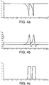
- the Figures 8 and 9 give examples of timing diagrams of the detection pulse signals H1, H2 and counting C1, C2 obtained with the asynchronous system, according to the embodiment of the figure 10 .
- the figure 8 illustrates a correlation case corresponding to the appearance of two convergent (concordant) H1 and H2 pulses, the H1 pulse completely covering H2 in this case.
- the state logic system can increment the first counter C1 corresponding to the pixel where appeared the first pulse from the initial edge B of this first pulse.
- the logic system can make the decision to increment or not the second counter C2 after the third transition C / D or C / B of the pulse signals present at the input.
- the state diagram of the asynchronous logic system illustrated on the figure 10 and corresponding to the sequences of input conditions and output setpoints of the Figures 8 and 9 , have five states A, B, C, D, E which are symmetrical from the point of view of the signals H1 / H2 and C1 / C2.
- the event count is active on the rising edges.
- reverse logic may be used.
- the initial state A corresponds to a state of rest in which the system transmits two counting signals C1 and C2 at a rest level, here the logic level 1. This state of rest is maintained as long as the pulse signals H1 and H2 remain at a rest level, here the logic level low 0.
- the logic system enters a cycle of states B and C.
- the first signal of counting C1 leaves the level of rest, here 1, and takes an active level, here the level 0, the second count signal C2 remaining at the rest level 1.
- the level of rest is in principle indifferent, it can be 0 or 1 .
- the logic system can perform either a return to the second state B of the A / B / C cycle, or a transition to a fourth state D belonging to another state cycle A / D / E , depending on whether one is in the case of the figure 8 or in the case of figure 9 that is, in a case of correlation or lack of correlation.
- illustrated figure 8 i.e., if the second signal pulse H2 ends before the end of the first pulse H1, and if the final edge of the second pulse H2- first appears, the system returns from the third state C to the second state B, the counting signals remaining at the same levels.
- the logic system leaves this second state B to return to the initial state of rest A by activating a transition of the first count signal C1 + which passes to level 1 here.
- the first counter CNT1 is thus incremented by one unit by the rising edge of the signal C1, here, while the second counter CNT2 is not incremented. , according to the provisions in the 3 rd case (see counting control of the previous table).
- the logic system performs the state cycle A / B / C / B / A and only the first counter C1 is incremented.
- the logic system transitions from the third state C to a fourth state D belonging to another cycle A / D / E.
- the rising edge transition C2 + causes the incrementation of the second counter CNT2.
- the logic system has therefore incremented by one unit each of the two counters CNT1 and CNT2 corresponding to each detectors DET1 and DET2, thus accounting for two events in accordance with the objective of processing two real uncorrelated events.
- the state diagram of the figure 10 shows again that the logic system according to the invention has transitions between the initial state A and the fourth state D as well as between it and a fifth state E. Indeed, if the system in the state of rest A receives a rising edge pulse H2 + first on the second input H2 (case not shown in the diagrams), it makes a transition to the state D during which the second count signal C2- is set to level 0.
- a final edge H2- occurs in the state D, for example if the pulse H2 returns immediately to the rest level 0 (case of an isolated pulse H2), the logic system returns to the initial state A of rest and the first count signal C2 returns to level 1 so that the counter CNT1 is incremented by one unit corresponding to this isolated event H1 during the cycle A / D / A.
- the transition from the state D to the state E occurs when a rising edge transition H1 + of the first input signal H1 is detected while the second input signal H2 is already in the active state. D.
- the logic system generates a falling edge C1- on the output of the first count signal C1.
- the logic system When the logic system is in the fifth state E and detects the final edge H1- of the pulse of the first input signal H1, i.e. if the first signal pulse H1 ends first (before any falling edge of the second input signal H2), the logic system returns to the fourth state D, the counting signals C1 and C2 remaining at the same levels.
- the state cycle A / D / E / D / A corresponds to incrementation operations INC2 of the second counter C2 and to the processing of another correlation case in which a signal pulse H2 has a time base that overlaps totally that of a signal pulse H1 (case not shown) and in which only the counter CNT2 is incremented during the changes of states D / A).
- the logic system according to the invention has therefore incremented by one unit each of the two counters CNT1 and CNT2 corresponding to each of the detectors DET1 and DET2, thus accounting for two events according to the objective of treating two real uncorrelated events.
- transition conditions H2 +, H2- and H1 +, H1- as well as the C2-, C2 + and C1- output setpoints of the fourth and fifth states D and E are the transpositions of the transition conditions H1 +, H1- and H2 +, H2- as well as respective C1-, C1 + and C2- output setpoints of the second and third states (by permutation of H1 and H2 as well as C1 and C2), the state diagram of the illustrated correlation means figures 4 , 7.10 being symmetrical from the point of view of inputs H1 and H2 as well as outputs C1 and C2.
- the preceding presentation of the embodiments of the invention deals with the case of the correlation of the pulse signals H1 and H2 of two acquisition chains AMP1 / CMP1 and AMP2 / CMP2 resulting from two adjacent detecting elements DET1 and DET2 (two neighboring pixels).
- the correlation means provided according to the invention can be used both for rejecting event matches between two neighboring pixels and for accepting event matches between any pixels, neighboring or otherwise.
- the invention is advantageously applied to radiation detection devices arranged according to a matrix architecture, in which the detection layer or layers constitute a network of related elementary detectors associated with an acquisition-chain matrix, notably those used in imaging.
- each acquisition chain can be connected to several neighboring acquisition chains, each link comprising correlation means able to compare the temporal overlap of the electrical signal transmitted by the chain with the signals concerned by the link.
- the correlation means of the acquisition and event counting circuits are arranged in a matrix arrangement, each correlation means being connected to a respective detector element and to at least one neighboring detector element, the means correlation being able to compare the time recovery of the connected pulse signals.
- the invention improves the quality of images obtained with matrix sensors by avoiding the loss of statistical information represented by the counting of false events and improves the performance and the quality of the imager, such as contrast and contrast. stung of the image.
- the invention applies in particular advantageously to the field of medical imaging, including X-ray imaging, a field in which any loss of information or degradation of performance would be detrimental to the quality of diagnosis.
- the invention is suitable for digital tomography devices, known as scanners, and in which it is advantageous to be able to reject the correlations or coincidences between neighboring pixels.
- the invention is still applicable to the case of electron-positron emission tomography (PET) tomography.
- PET electron-positron emission tomography
- each recombination of an electron with a positron generates the simultaneous emission of two ⁇ rays in opposite directions at an angle of 180 °.
- the correlation means are used to detect such coincidences, except that this time we accept the coincidences, that is to say that in case of correlation of event detection by two detectors located in opposite zones, the correlation is accepted instead of rejecting this case, and a corresponding counter is incremented. Consequently, in the event of non-correlation, that is to say, in the event of detecting time-delayed detection events that do not correspond to true recombination, it is considered to be false events. and the counter associated with the two detectors is not incremented.
- the invention can also be realized with a radiation detection device comprising a plurality of detector elements, each detector element being associated with a pulse signal acquisition and detection event counting circuit.
- device comprising means for correlating the detection events corresponding to two detector elements and receiving the pulse signals from the respective detector elements, located in particular in opposite zones, each correlation means controlling counting means corresponding to the two paired detector elements and being implemented to count a detection event when two pulse signals are correlated (or match) and to not count events when two pulse signals diverge or are not correlated.
- the invention thus applies to the fields of measuring exposure to other types of radiation, such as image-based imaging.
- emission of electron-positron pairs positron camera
- remote sensing of ⁇ , ⁇ , ⁇ radiations imaging in visible light or beyond the visible (ultraviolet radiation photons and wavelengths below, photons InfraRed radiation and wavelengths beyond).
Landscapes
- Physics & Mathematics (AREA)
- Health & Medical Sciences (AREA)
- Life Sciences & Earth Sciences (AREA)
- General Physics & Mathematics (AREA)
- High Energy & Nuclear Physics (AREA)
- Molecular Biology (AREA)
- Spectroscopy & Molecular Physics (AREA)
- Measurement Of Radiation (AREA)
Claims (12)
- Vorrichtung zum Detektieren von Strahlungen, enthaltend eine Mehrzahl von Detektorelementen (DET1, DET2), wobei jedem Detektorelement (DET1) eine entsprechende Schaltung (AMP1 - CMP1) zum Erfassen von Impulssignalen (H1) und zum Zählen (CNT1) von Detektionsereignissen zugeordnet ist, wobei die Vorrichtung Mittel (COR) zur Korrelation der Detektionsereignisse enthält, die zumindest zwei Detektorelementen (DET1/DET2) entsprechen, dadurch gekennzeichnet, dass diese Korrelationsmittel dazu geeignet sind, Fälle (C01) von Korrelation bzw. Übereinstimmung bei zeitlicher Überlagerung eines Impulssignals (H2) mit einem weiteren Impulssignal (H1) und Fälle (UNCO1/2) von Nicht-Korrelation bei einfacher Zeitverschiebung eines Impulssignals (H2) gegenüber einem weiteren Impulssignal (H1) mit teilweiser Überlagerung dieser beiden Signale zu unterscheiden.
- Vorrichtung nach Anspruch 1, wobei die Korrelationsmittel (COR) dazu ausgelegt sind, zumindest zwei Impulssignale (H1, H2) zu empfangen, die von jeweiligen Detektorelementen (DET1, DET2) stammen, und Zählmittel (CNT1, CNT2) zu steuern, die dem jeweiligen Detektorelement entsprechen, so dass ein einziges Detektionsereignis dann erfasst wird (C1), wenn beide Impulssignale übereinstimmen (H1 c H2).
- Vorrichtung nach Anspruch 1 oder 2, wobei die Mittel (COR) zur Korrelation von Ereignissen dazu ausgelegt sind, die zeitliche Überlagerung eines von einem Detektorelement (DET1) stammenden Impulssignals (H) bezüglich eines weiteren, von einem weiteren Detektorelement (DET2) stammenden Impulssignals zu vergleichen.
- Vorrichtung nach einem der Ansprüche 1 bis 3, wobei die Korrelationsmittel (COR) dazu geeignet sind, Fälle (CO1) von Korrelation bzw. Übereinstimmung, bei denen die Zeitbasis eines Impulses (H1) die Zeitbasis eines weiteren Impulses (H2) vollständig überlagert, gegenüber Fällen (UNCO1/2) von Nicht-Korrelation zu unterscheiden, bei denen die Zeitbasis eines Impulses (H1) die Zeitbasis eines weiteren Impulses (H2) teilweise oder gar nicht überlagert.
- Vorrichtung nach einem der Ansprüche 1 bis 4, wobei die Korrelationsmittel (COR) dazu ausgelegt sind, um:- Zählmittel (CNT1) zu inkrementieren (C1), die jedem von einem jeweiligen Detektorelement (DET1) stammenden Impulssignal (H1) entsprechen, solange das Impulssignal (H1) isoliert auftritt,- nur eines der entsprechenden Zählmittel (CNT1) zu inkrementieren (C1), wenn zwei Impulssignale (H1, H2) korreliert werden (CO1), wobei die Zeitdauer des ersten Impulses (H1) die Zeitdauer des zweiten Impulses (H2) zeitlich überlagert; und/oder- die beiden entsprechenden Zählmittel (CNT1 & CNT2) zu inkrementieren (C1, C2), wenn zwei Impulssignale (H1, H2) dekorreliert werden (UNCO1/2), wobei die Zeitdauer des ersten Impulses (H1) die Zeitdauer des zweiten Impulses (H2) zeitlich teilweise oder gar nicht überlagert.
- Vorrichtung nach einem der Ansprüche 1 bis 5, wobei die Korrelationsmittel (COR) über eine asynchrone Logik (a, b, c, d, e) verfügen, die dazu geeignet sind, Chronologien des Auftretens von Übergängen (H1+, H1-, H2+, H2-) von zumindest zwei Impulssignalen (H1, H2) zu vergleichen, die von jeweiligen Detektorelementen (DET1, DET2) stammen.
- Vorrichtung nach einem der Ansprüche 1 bis 6, wobei die Korrelationsmittel (COR) dazu ausgelegt sind, einen Fall von Korrelation bzw. Übereinstimmung zu detektieren, wenn eine ansteigende Flanke (H1+) eines ersten Impulssignals (H1) von einer ansteigenden Flanke (H2+) eines zweiten Impulssignals (H2) gefolgt wird, die ihrerseits von einer abfallenden Flanke (H2-) des zweiten Impulssignals gefolgt wird.
- Vorrichtung nach einem der Ansprüche 1 bis 7, wobei die Korrelationsmittel (COR) dazu ausgelegt sind, einen Fall von Nicht-Korrelation zu detektieren, wenn eine ansteigende Flanke (H1+) eines ersten Impulssignals (H1) von einer ansteigenden Flanke (H2+) eines zweiten Impulssignals (H2) gefolgt wird, die ihrerseits von einer abfallenden Flanke (H1-) des ersten Impulssignals gefolgt wird.
- Vorrichtung nach einem der Ansprüche 1 bis 8, wobei dann, wenn eine ansteigende Flanke (H1+) eines von einem Detektorelement (DET1) stammenden ersten Impulssignals (H1) von einer ansteigenden Flanke (H2+) eines von einem weiteren Detektorelement (DET2) stammenden zweiten Impulssignals (H2) gefolgt wird, die Korrelationsmittel (COR) dazu ausgelegt sind, um:- ein erstes Zählsignal (C1) zu erzeugen und- entweder ein zweites Zählsignal (C2) zu erzeugen, wenn (UNCO1/2) die abfallende Flanke (H1-) des ersten Impulssignals vor der abfallenden Flanke (H2-) des zweiten Impulssignals erscheint,- oder kein weiteres Zählsignal zu erzeugen, wenn die abfallende Flanke (H2-) des zweiten Impulssignals vor der abfallenden Flanke (H1-) des ersten Impulssignals erscheint.
- Vorrichtung nach einem der Ansprüche 1 bis 9, wobei die Korrelationsmittel (COE) dazu ausgelegt sind, zumindest ein erstes Eingangssignal (H1) und ein zweites Eingangssignal (H2) zu empfangen, die von zwei Detektorelementen (DET1, DET2) stammen, und am Ausgang zumindest ein erstes und ein zweites Zählsignal (C1, C2) auszusenden, wobei die Korrelationsmittel über eine asynchrone Zustandslogik (A, B, C, D, E) verfügen, enthaltend:- Mittel, damit dann, wenn die Eingangssignale in einem anfänglichen Ruhezustand (A) (H1 = H2 = 0) vorliegen, das erste und das zweite Zählsignal auf einem Ruhepegel bleiben,- Mittel (B), damit dann, wenn das erste Eingangssignal (H1) vom anfänglichen Ruhezustand in einen aktiven Zustand (H1+) übergeht, das erste Zählsignal einen Zustandsübergang zu einem ersten Pegel (C1-) vollzieht,- Mittel (C), damit dann, wenn das zweite Eingangssignal (H2) in den aktiven Zustand (H2+) übergeht, während das erste Eingangssignal (H1) im aktiven Zustand ist, das zweite Zählsignal einen Zustandsübergang zu einem ersten Pegel (C2-) vollzieht,- Mittel (C/D), damit dann, wenn das erste Eingangssignal den aktiven Zustand (H1-) verlässt, während das zweite Eingangssignal (H2) im aktiven Zustand ist, das erste Zählsignal einen Zustandsübergang zu einem zweiten Pegel (C1 +) vollzieht,- Mittel (D), damit dann, wenn das zweite Eingangssignal (H2) vom anfänglichen Ruhezustand in einen aktiven Zustand (H2+) übergeht, das zweite Zählsignal einen Zustandsübergang zu einem ersten Pegel (C2-) vollzieht,- Mittel (E), damit dann, wenn das erste Eingangssignal (H1) in den aktiven Zustand (H1+) übergeht, während das zweite Eingangssignal (H2) im aktiven Zustand ist, das erste Zählsignal einen Zustandsübergang zu einem ersten Pegel (C1-) vollzieht,- Mittel (E/B), damit dann, wenn das zweite Eingangssignal den aktiven Zustand (H2-) verlässt, während das erste Eingangssignal (H1) im aktiven Zustand ist, das zweite Zählsignal einen Zustandsübergang zu einem zweiten Pegel (C2+) vollzieht.
- Vorrichtung nach einem der Ansprüche 1 bis 10, wobei die Korrelationsmittel (COR) über eine asynchrone Zustandslogik verfügen, die zumindest fünf Zustandsspeicher (a, b, c, d, e) aufweist.
- Vorrichtung nach einem der Ansprüche 1 bis 11, wobei die Korrelationsmittel für die Erfassungs- und Ereigniszählschaltungen gemäß einer Matrixanordnung angeordnet sind, wobei jedes Korrelationsmittel mit einem jeweiligen Detektorelement und mit zumindest einem benachbarten Detektorelement verbunden ist, wobei die Korrelationsmittel dazu ausgelegt sind, die zeitliche Überlagerung der verbundenen Impulssignale zu vergleichen.
Applications Claiming Priority (2)
| Application Number | Priority Date | Filing Date | Title |
|---|---|---|---|
| FR0351233A FR2864731B1 (fr) | 2003-12-30 | 2003-12-30 | Systeme de detection de rayonnements permettant un meilleur comptage d'evenements |
| FR0351233 | 2003-12-30 |
Publications (3)
| Publication Number | Publication Date |
|---|---|
| EP1550884A2 EP1550884A2 (de) | 2005-07-06 |
| EP1550884A3 EP1550884A3 (de) | 2005-07-13 |
| EP1550884B1 true EP1550884B1 (de) | 2017-07-05 |
Family
ID=34566397
Family Applications (1)
| Application Number | Title | Priority Date | Filing Date |
|---|---|---|---|
| EP04107019.4A Expired - Lifetime EP1550884B1 (de) | 2003-12-30 | 2004-12-28 | Strahlungsdetektor mit einer Mehrzahl von Detektorelementen, jedes mit einer Erfassungsschaltung und einer Zählschaltung |
Country Status (3)
| Country | Link |
|---|---|
| US (1) | US7214944B2 (de) |
| EP (1) | EP1550884B1 (de) |
| FR (1) | FR2864731B1 (de) |
Families Citing this family (30)
| Publication number | Priority date | Publication date | Assignee | Title |
|---|---|---|---|---|
| DE102004048962B4 (de) * | 2004-10-07 | 2006-09-21 | Siemens Ag | Digitale Röntgenaufnahmevorrichtung bzw. Verfahren zur Aufnahme von Röntgenabbildungen in einer digitalen Röntgenaufnahmevorrichtung |
| CN101600974B (zh) * | 2007-02-01 | 2013-03-13 | 皇家飞利浦电子股份有限公司 | 用于光子计数探测器的事件共享恢复 |
| JP5143471B2 (ja) * | 2007-05-08 | 2013-02-13 | 株式会社日立製作所 | イメージング装置 |
| US8269181B2 (en) * | 2007-10-10 | 2012-09-18 | Positron Corporation | Avalanche pixel sensors and related methods |
| US7763861B1 (en) * | 2007-10-23 | 2010-07-27 | Xilinx, Inc. | Determining a characteristic of atomic particles affecting a programmable logic device |
| US8405038B2 (en) * | 2009-12-30 | 2013-03-26 | General Electric Company | Systems and methods for providing a shared charge in pixelated image detectors |
| US9425234B2 (en) | 2010-07-15 | 2016-08-23 | Leigh E. Colby | Quantum dot digital radiographic detection system |
| US9422159B2 (en) * | 2010-07-15 | 2016-08-23 | Leigh E. Colby | Quantum dot digital radiographic detection system |
| US8901503B2 (en) * | 2012-04-19 | 2014-12-02 | Canberra Industries, Inc. | Radiation detector system and method |
| US9329283B2 (en) | 2012-12-21 | 2016-05-03 | Commissariat A L'energie Atomique Et Aux Energies Alternatives | Semiconductor-detector-based method and device for detecting ionising radiation |
| US9002084B2 (en) | 2013-08-30 | 2015-04-07 | Ge Medical Systems Israel, Ltd | Systems and methods for summing signals from an imaging detector |
| FR3010534B1 (fr) * | 2013-09-06 | 2015-10-09 | Commissariat Energie Atomique | Systeme et procede de detection de rayonnements neutron, gamma et muon avec des scintillateurs plastiques contigus |
| CN104035119B (zh) * | 2014-06-06 | 2016-04-13 | 成都理工大学 | 肺部不均匀γ内污染探测装置 |
| US9482764B1 (en) | 2015-05-28 | 2016-11-01 | General Electric Company | Systems and methods for charge-sharing identification and correction using a single pixel |
| US12298454B2 (en) | 2015-08-10 | 2025-05-13 | Shanghai United Imaging Healthcare Co., Ltd. | Apparatus and method for PET detector |
| US9696439B2 (en) | 2015-08-10 | 2017-07-04 | Shanghai United Imaging Healthcare Co., Ltd. | Apparatus and method for PET detector |
| US10156645B2 (en) | 2016-12-23 | 2018-12-18 | General Electric Company | Systems and methods for sub-pixel location determination at sidewalls and corners of detectors |
| WO2018133087A1 (en) | 2017-01-23 | 2018-07-26 | Shenzhen Xpectvision Technology Co., Ltd. | X-ray detectors capable of identifying and managing charge sharing |
| US10162066B2 (en) * | 2017-02-06 | 2018-12-25 | General Electric Company | Coincidence-enabling photon-counting detector |
| US10145964B1 (en) | 2017-05-15 | 2018-12-04 | General Electric Company | Systems and methods for improved collimation sensitivity |
| US10324200B2 (en) | 2017-05-15 | 2019-06-18 | General Electric Company | Systems and methods for improved collimation sensitivity |
| US9983320B1 (en) | 2017-05-15 | 2018-05-29 | General Electric Company | Systems and methods for improved collimation sensitivity |
| JP2019204887A (ja) * | 2018-05-24 | 2019-11-28 | 株式会社豊田中央研究所 | 光検出器及びそれを用いた光学測距装置 |
| US10761224B2 (en) | 2018-06-06 | 2020-09-01 | General Electric Company | Systems and methods for improved detector assembly sizing |
| US10976452B2 (en) | 2018-08-13 | 2021-04-13 | General Electric Medical Systems Israel, Ltd. (Il) | Systems and methods for improved medical imaging |
| US10481285B1 (en) | 2018-08-13 | 2019-11-19 | General Electric Company | Systems and methods for determination of depth of interaction |
| US10591619B2 (en) | 2018-08-15 | 2020-03-17 | GE Precision Healthcare LLC | Anodes for improved detection of non-collected adjacent signals |
| US10247834B1 (en) | 2018-08-15 | 2019-04-02 | General Electric Company | Anodes for improved detection of non-collected adjacent signal |
| US11092701B1 (en) | 2020-07-07 | 2021-08-17 | GE Precision Healthcare LLC | Systems and methods for improved medical imaging |
| US11320545B2 (en) | 2020-07-07 | 2022-05-03 | GE Precision Healthcare LLC | Systems and methods for improved medical imaging |
Citations (1)
| Publication number | Priority date | Publication date | Assignee | Title |
|---|---|---|---|---|
| WO2001027656A1 (en) * | 1999-10-08 | 2001-04-19 | Mamea Imaging Ab | Method and arrangement relating to x-ray imaging |
Family Cites Families (8)
| Publication number | Priority date | Publication date | Assignee | Title |
|---|---|---|---|---|
| SU409164A1 (ru) * | 1972-04-13 | 1973-11-30 | Автор нзобретепи | Устройство для компенсации наложения электрических импульсов |
| GB1406685A (en) * | 1972-12-13 | 1975-09-17 | Baird Atomic Inc | Sensing matrices for radioactivity-distribution detectors |
| US4658216A (en) * | 1983-07-14 | 1987-04-14 | The United States Of America As Represented By The Department Of Energy | High resolution, high rate X-ray spectrometer |
| JP3418800B2 (ja) * | 1994-02-03 | 2003-06-23 | 株式会社原子力エンジニアリング | 放射線測定の消滅γ線の低減方法 |
| US5606167A (en) * | 1994-07-11 | 1997-02-25 | Miller; Thomas G. | Contraband detection apparatus and method |
| FR2847677B1 (fr) * | 2002-11-26 | 2005-01-07 | Commissariat Energie Atomique | Detecteur de particules et dispositif de comptage comprenant une pluralite de detecteurs de particules |
| FR2847678B1 (fr) | 2002-11-27 | 2005-01-07 | Commissariat Energie Atomique | Detecteur de particules et procede de detection de particules associe |
| US7045802B2 (en) * | 2003-11-26 | 2006-05-16 | General Electric Company | Method and apparatus for coincidence imaging digital triggering |
-
2003
- 2003-12-30 FR FR0351233A patent/FR2864731B1/fr not_active Expired - Fee Related
-
2004
- 2004-12-20 US US11/014,868 patent/US7214944B2/en not_active Expired - Fee Related
- 2004-12-28 EP EP04107019.4A patent/EP1550884B1/de not_active Expired - Lifetime
Patent Citations (1)
| Publication number | Priority date | Publication date | Assignee | Title |
|---|---|---|---|---|
| WO2001027656A1 (en) * | 1999-10-08 | 2001-04-19 | Mamea Imaging Ab | Method and arrangement relating to x-ray imaging |
Also Published As
| Publication number | Publication date |
|---|---|
| EP1550884A3 (de) | 2005-07-13 |
| US20050139777A1 (en) | 2005-06-30 |
| FR2864731A1 (fr) | 2005-07-01 |
| FR2864731B1 (fr) | 2006-02-03 |
| US7214944B2 (en) | 2007-05-08 |
| EP1550884A2 (de) | 2005-07-06 |
Similar Documents
| Publication | Publication Date | Title |
|---|---|---|
| EP1550884A2 (de) | Strahlungsdetektor mit einer Mehrzahl von Detektorelementen, jedes mit einer Erfassungsschaltung und einer Zählschaltung | |
| EP2507652B1 (de) | Verfahren zur kalibrierung eines röntgendetektors | |
| JP5701743B2 (ja) | 放射線検出器、画像システム、光子を検出するための方法及びその方法を実行するコンピュータプログラム | |
| CN108291961B (zh) | 固体摄像装置、距离测定装置及距离测定方法 | |
| US8440957B2 (en) | Counting pixel with good dynamic range properties | |
| CN108139487B (zh) | 光子计数设备和方法 | |
| US7439518B2 (en) | Multi-layer pixellated gamma-ray detector | |
| US9103924B2 (en) | High throughput detector array | |
| US20090109313A1 (en) | Self-Triggering CMOS Image Sensor | |
| EP2510338A1 (de) | Verfahren und vorrichtung zur erkennung eines materials mittels übertragungsfunktion | |
| US9029793B2 (en) | Imaging device | |
| TW201515204A (zh) | 影像捕獲器件,輻射偵測裝置,以及用於影像捕獲器件之控制方法 | |
| FR2754606A1 (fr) | Dispositif et procede de collection et de codage de signaux issus de photodetecteurs | |
| WO2003081899A1 (en) | Event-driven charge-coupled device design and applications therefor | |
| JP2021193759A (ja) | 固体撮像装置、放射線検出器及び放射線計測システム | |
| US7476840B2 (en) | Sensing light and sensing the state of a memory cell an aid of a switch controlled by a schmidt trigger | |
| EP2936208B1 (de) | Auf halbleiterdetektor basierendes verfahren und vorrichtung zur erfassung ionisierender strahlung | |
| US20090108311A1 (en) | CMOS Detector with Reduced Sensitivity to X-Rays | |
| FR3101768A1 (fr) | Capteur d’image radiologique intra-oral a pixels actifs et procede de prise d’image associe | |
| FR3002650A1 (fr) | Dispositif de traitement d'un signal delivre par un detecteur de rayonnement | |
| US11770627B1 (en) | Systems and methods for direct measurement of photon arrival rate | |
| Walasek-Höhne et al. | Video Cameras used in Beam Instrumentation--an Overview | |
| EP3051316B1 (de) | Elektronischer schaltkreis, der zur steuerung eines erfassungsmoduls einer photonendetektionsvorrichtung konfiguriert ist, steuerverfahren und entsprechendes computerprogramm | |
| GB2294540A (en) | Determing position and time of scintillation event | |
| FR3017962A1 (fr) | Outil de detection de rayonnement photonique particulierement adapte a des rayonnements a fort flux |
Legal Events
| Date | Code | Title | Description |
|---|---|---|---|
| PUAI | Public reference made under article 153(3) epc to a published international application that has entered the european phase |
Free format text: ORIGINAL CODE: 0009012 |
|
| PUAL | Search report despatched |
Free format text: ORIGINAL CODE: 0009013 |
|
| AK | Designated contracting states |
Kind code of ref document: A2 Designated state(s): AT BE BG CH CY CZ DE DK EE ES FI FR GB GR HU IE IS IT LI LT LU MC NL PL PT RO SE SI SK TR |
|
| AX | Request for extension of the european patent |
Extension state: AL BA HR LV MK YU |
|
| AK | Designated contracting states |
Kind code of ref document: A3 Designated state(s): AT BE BG CH CY CZ DE DK EE ES FI FR GB GR HU IE IS IT LI LT LU MC NL PL PT RO SE SI SK TR |
|
| AX | Request for extension of the european patent |
Extension state: AL BA HR LV MK YU |
|
| 17P | Request for examination filed |
Effective date: 20060107 |
|
| AKX | Designation fees paid |
Designated state(s): AT BE BG CH CY CZ DE DK EE ES FI FR GB GR HU IE IS IT LI LT LU MC NL PL PT RO SE SI SK TR |
|
| RAP1 | Party data changed (applicant data changed or rights of an application transferred) |
Owner name: COMMISSARIAT A L'ENERGIE ATOMIQUE |
|
| RAP1 | Party data changed (applicant data changed or rights of an application transferred) |
Owner name: COMMISSARIAT A L'ENERGIE ATOMIQUE ET AUX ENERGIES |
|
| 17Q | First examination report despatched |
Effective date: 20141021 |
|
| STAA | Information on the status of an ep patent application or granted ep patent |
Free format text: STATUS: EXAMINATION IS IN PROGRESS |
|
| REG | Reference to a national code |
Ref country code: DE Ref legal event code: R079 Ref document number: 602004051486 Country of ref document: DE Free format text: PREVIOUS MAIN CLASS: G01T0001164000 Ipc: G01T0001170000 |
|
| GRAP | Despatch of communication of intention to grant a patent |
Free format text: ORIGINAL CODE: EPIDOSNIGR1 |
|
| STAA | Information on the status of an ep patent application or granted ep patent |
Free format text: STATUS: GRANT OF PATENT IS INTENDED |
|
| RIC1 | Information provided on ipc code assigned before grant |
Ipc: G01T 1/172 20060101ALI20170206BHEP Ipc: G01T 1/17 20060101AFI20170206BHEP |
|
| INTG | Intention to grant announced |
Effective date: 20170221 |
|
| GRAS | Grant fee paid |
Free format text: ORIGINAL CODE: EPIDOSNIGR3 |
|
| GRAA | (expected) grant |
Free format text: ORIGINAL CODE: 0009210 |
|
| STAA | Information on the status of an ep patent application or granted ep patent |
Free format text: STATUS: THE PATENT HAS BEEN GRANTED |
|
| AK | Designated contracting states |
Kind code of ref document: B1 Designated state(s): AT BE BG CH CY CZ DE DK EE ES FI FR GB GR HU IE IS IT LI LT LU MC NL PL PT RO SE SI SK TR |
|
| REG | Reference to a national code |
Ref country code: GB Ref legal event code: FG4D Free format text: NOT ENGLISH |
|
| REG | Reference to a national code |
Ref country code: CH Ref legal event code: EP |
|
| REG | Reference to a national code |
Ref country code: AT Ref legal event code: REF Ref document number: 906973 Country of ref document: AT Kind code of ref document: T Effective date: 20170715 |
|
| REG | Reference to a national code |
Ref country code: IE Ref legal event code: FG4D Free format text: LANGUAGE OF EP DOCUMENT: FRENCH |
|
| REG | Reference to a national code |
Ref country code: DE Ref legal event code: R096 Ref document number: 602004051486 Country of ref document: DE |
|
| REG | Reference to a national code |
Ref country code: NL Ref legal event code: MP Effective date: 20170705 |
|
| REG | Reference to a national code |
Ref country code: AT Ref legal event code: MK05 Ref document number: 906973 Country of ref document: AT Kind code of ref document: T Effective date: 20170705 |
|
| REG | Reference to a national code |
Ref country code: LT Ref legal event code: MG4D |
|
| PG25 | Lapsed in a contracting state [announced via postgrant information from national office to epo] |
Ref country code: LT Free format text: LAPSE BECAUSE OF FAILURE TO SUBMIT A TRANSLATION OF THE DESCRIPTION OR TO PAY THE FEE WITHIN THE PRESCRIBED TIME-LIMIT Effective date: 20170705 Ref country code: AT Free format text: LAPSE BECAUSE OF FAILURE TO SUBMIT A TRANSLATION OF THE DESCRIPTION OR TO PAY THE FEE WITHIN THE PRESCRIBED TIME-LIMIT Effective date: 20170705 Ref country code: NL Free format text: LAPSE BECAUSE OF FAILURE TO SUBMIT A TRANSLATION OF THE DESCRIPTION OR TO PAY THE FEE WITHIN THE PRESCRIBED TIME-LIMIT Effective date: 20170705 Ref country code: FI Free format text: LAPSE BECAUSE OF FAILURE TO SUBMIT A TRANSLATION OF THE DESCRIPTION OR TO PAY THE FEE WITHIN THE PRESCRIBED TIME-LIMIT Effective date: 20170705 Ref country code: SE Free format text: LAPSE BECAUSE OF FAILURE TO SUBMIT A TRANSLATION OF THE DESCRIPTION OR TO PAY THE FEE WITHIN THE PRESCRIBED TIME-LIMIT Effective date: 20170705 |
|
| PG25 | Lapsed in a contracting state [announced via postgrant information from national office to epo] |
Ref country code: ES Free format text: LAPSE BECAUSE OF FAILURE TO SUBMIT A TRANSLATION OF THE DESCRIPTION OR TO PAY THE FEE WITHIN THE PRESCRIBED TIME-LIMIT Effective date: 20170705 Ref country code: PL Free format text: LAPSE BECAUSE OF FAILURE TO SUBMIT A TRANSLATION OF THE DESCRIPTION OR TO PAY THE FEE WITHIN THE PRESCRIBED TIME-LIMIT Effective date: 20170705 Ref country code: IS Free format text: LAPSE BECAUSE OF FAILURE TO SUBMIT A TRANSLATION OF THE DESCRIPTION OR TO PAY THE FEE WITHIN THE PRESCRIBED TIME-LIMIT Effective date: 20171105 Ref country code: BG Free format text: LAPSE BECAUSE OF FAILURE TO SUBMIT A TRANSLATION OF THE DESCRIPTION OR TO PAY THE FEE WITHIN THE PRESCRIBED TIME-LIMIT Effective date: 20171005 Ref country code: GR Free format text: LAPSE BECAUSE OF FAILURE TO SUBMIT A TRANSLATION OF THE DESCRIPTION OR TO PAY THE FEE WITHIN THE PRESCRIBED TIME-LIMIT Effective date: 20171006 |
|
| REG | Reference to a national code |
Ref country code: DE Ref legal event code: R097 Ref document number: 602004051486 Country of ref document: DE |
|
| PG25 | Lapsed in a contracting state [announced via postgrant information from national office to epo] |
Ref country code: DK Free format text: LAPSE BECAUSE OF FAILURE TO SUBMIT A TRANSLATION OF THE DESCRIPTION OR TO PAY THE FEE WITHIN THE PRESCRIBED TIME-LIMIT Effective date: 20170705 Ref country code: CZ Free format text: LAPSE BECAUSE OF FAILURE TO SUBMIT A TRANSLATION OF THE DESCRIPTION OR TO PAY THE FEE WITHIN THE PRESCRIBED TIME-LIMIT Effective date: 20170705 Ref country code: RO Free format text: LAPSE BECAUSE OF FAILURE TO SUBMIT A TRANSLATION OF THE DESCRIPTION OR TO PAY THE FEE WITHIN THE PRESCRIBED TIME-LIMIT Effective date: 20170705 |
|
| PLBE | No opposition filed within time limit |
Free format text: ORIGINAL CODE: 0009261 |
|
| STAA | Information on the status of an ep patent application or granted ep patent |
Free format text: STATUS: NO OPPOSITION FILED WITHIN TIME LIMIT |
|
| PG25 | Lapsed in a contracting state [announced via postgrant information from national office to epo] |
Ref country code: IT Free format text: LAPSE BECAUSE OF FAILURE TO SUBMIT A TRANSLATION OF THE DESCRIPTION OR TO PAY THE FEE WITHIN THE PRESCRIBED TIME-LIMIT Effective date: 20170705 Ref country code: EE Free format text: LAPSE BECAUSE OF FAILURE TO SUBMIT A TRANSLATION OF THE DESCRIPTION OR TO PAY THE FEE WITHIN THE PRESCRIBED TIME-LIMIT Effective date: 20170705 Ref country code: SK Free format text: LAPSE BECAUSE OF FAILURE TO SUBMIT A TRANSLATION OF THE DESCRIPTION OR TO PAY THE FEE WITHIN THE PRESCRIBED TIME-LIMIT Effective date: 20170705 |
|
| 26N | No opposition filed |
Effective date: 20180406 |
|
| REG | Reference to a national code |
Ref country code: DE Ref legal event code: R119 Ref document number: 602004051486 Country of ref document: DE |
|
| REG | Reference to a national code |
Ref country code: CH Ref legal event code: PL |
|
| GBPC | Gb: european patent ceased through non-payment of renewal fee |
Effective date: 20171228 |
|
| PG25 | Lapsed in a contracting state [announced via postgrant information from national office to epo] |
Ref country code: SI Free format text: LAPSE BECAUSE OF FAILURE TO SUBMIT A TRANSLATION OF THE DESCRIPTION OR TO PAY THE FEE WITHIN THE PRESCRIBED TIME-LIMIT Effective date: 20170705 |
|
| REG | Reference to a national code |
Ref country code: IE Ref legal event code: MM4A |
|
| PG25 | Lapsed in a contracting state [announced via postgrant information from national office to epo] |
Ref country code: LU Free format text: LAPSE BECAUSE OF NON-PAYMENT OF DUE FEES Effective date: 20171228 |
|
| REG | Reference to a national code |
Ref country code: FR Ref legal event code: ST Effective date: 20180831 |
|
| REG | Reference to a national code |
Ref country code: BE Ref legal event code: MM Effective date: 20171231 |
|
| PG25 | Lapsed in a contracting state [announced via postgrant information from national office to epo] |
Ref country code: FR Free format text: LAPSE BECAUSE OF NON-PAYMENT OF DUE FEES Effective date: 20180102 Ref country code: DE Free format text: LAPSE BECAUSE OF NON-PAYMENT OF DUE FEES Effective date: 20180703 Ref country code: IE Free format text: LAPSE BECAUSE OF NON-PAYMENT OF DUE FEES Effective date: 20171228 |
|
| PG25 | Lapsed in a contracting state [announced via postgrant information from national office to epo] |
Ref country code: CH Free format text: LAPSE BECAUSE OF NON-PAYMENT OF DUE FEES Effective date: 20171231 Ref country code: BE Free format text: LAPSE BECAUSE OF NON-PAYMENT OF DUE FEES Effective date: 20171231 Ref country code: LI Free format text: LAPSE BECAUSE OF NON-PAYMENT OF DUE FEES Effective date: 20171231 Ref country code: GB Free format text: LAPSE BECAUSE OF NON-PAYMENT OF DUE FEES Effective date: 20171228 |
|
| PG25 | Lapsed in a contracting state [announced via postgrant information from national office to epo] |
Ref country code: MC Free format text: LAPSE BECAUSE OF FAILURE TO SUBMIT A TRANSLATION OF THE DESCRIPTION OR TO PAY THE FEE WITHIN THE PRESCRIBED TIME-LIMIT Effective date: 20170705 Ref country code: HU Free format text: LAPSE BECAUSE OF FAILURE TO SUBMIT A TRANSLATION OF THE DESCRIPTION OR TO PAY THE FEE WITHIN THE PRESCRIBED TIME-LIMIT; INVALID AB INITIO Effective date: 20041228 |
|
| PG25 | Lapsed in a contracting state [announced via postgrant information from national office to epo] |
Ref country code: CY Free format text: LAPSE BECAUSE OF NON-PAYMENT OF DUE FEES Effective date: 20170705 |
|
| PG25 | Lapsed in a contracting state [announced via postgrant information from national office to epo] |
Ref country code: TR Free format text: LAPSE BECAUSE OF FAILURE TO SUBMIT A TRANSLATION OF THE DESCRIPTION OR TO PAY THE FEE WITHIN THE PRESCRIBED TIME-LIMIT Effective date: 20170705 |
|
| PG25 | Lapsed in a contracting state [announced via postgrant information from national office to epo] |
Ref country code: PT Free format text: LAPSE BECAUSE OF FAILURE TO SUBMIT A TRANSLATION OF THE DESCRIPTION OR TO PAY THE FEE WITHIN THE PRESCRIBED TIME-LIMIT Effective date: 20170705 |