EP1549890B1 - Pervaporativ gekühlte behälter - Google Patents
Pervaporativ gekühlte behälter Download PDFInfo
- Publication number
- EP1549890B1 EP1549890B1 EP03734378A EP03734378A EP1549890B1 EP 1549890 B1 EP1549890 B1 EP 1549890B1 EP 03734378 A EP03734378 A EP 03734378A EP 03734378 A EP03734378 A EP 03734378A EP 1549890 B1 EP1549890 B1 EP 1549890B1
- Authority
- EP
- European Patent Office
- Prior art keywords
- matrix
- pervaporative
- container
- porous
- liquid
- Prior art date
- Legal status (The legal status is an assumption and is not a legal conclusion. Google has not performed a legal analysis and makes no representation as to the accuracy of the status listed.)
- Expired - Lifetime
Links
- 239000011159 matrix material Substances 0.000 claims abstract description 110
- 239000007788 liquid Substances 0.000 claims abstract description 101
- 238000001816 cooling Methods 0.000 claims abstract description 52
- 239000000463 material Substances 0.000 claims abstract description 48
- 238000005373 pervaporation Methods 0.000 claims abstract description 12
- 238000001704 evaporation Methods 0.000 claims abstract description 9
- 230000008020 evaporation Effects 0.000 claims abstract description 9
- 239000011148 porous material Substances 0.000 claims description 51
- -1 polyethylene Polymers 0.000 claims description 37
- 230000002209 hydrophobic effect Effects 0.000 claims description 18
- 239000004698 Polyethylene Substances 0.000 claims description 17
- 229920001343 polytetrafluoroethylene Polymers 0.000 claims description 17
- 239000004810 polytetrafluoroethylene Substances 0.000 claims description 17
- 229920000573 polyethylene Polymers 0.000 claims description 11
- 239000012530 fluid Substances 0.000 claims description 10
- 239000002250 absorbent Substances 0.000 claims description 4
- 230000002745 absorbent Effects 0.000 claims description 4
- 239000002274 desiccant Substances 0.000 claims description 4
- 239000002245 particle Substances 0.000 claims description 4
- 238000001035 drying Methods 0.000 claims description 2
- XLYOFNOQVPJJNP-UHFFFAOYSA-N water Substances O XLYOFNOQVPJJNP-UHFFFAOYSA-N 0.000 abstract description 33
- LFQSCWFLJHTTHZ-UHFFFAOYSA-N Ethanol Chemical compound CCO LFQSCWFLJHTTHZ-UHFFFAOYSA-N 0.000 abstract description 5
- 235000013361 beverage Nutrition 0.000 abstract description 4
- 239000010410 layer Substances 0.000 description 40
- 238000000034 method Methods 0.000 description 39
- 229920003023 plastic Polymers 0.000 description 22
- 239000004033 plastic Substances 0.000 description 22
- 230000004907 flux Effects 0.000 description 19
- 230000008569 process Effects 0.000 description 18
- 238000012546 transfer Methods 0.000 description 13
- 239000012528 membrane Substances 0.000 description 11
- 229920001971 elastomer Polymers 0.000 description 9
- 239000000806 elastomer Substances 0.000 description 9
- 238000009834 vaporization Methods 0.000 description 9
- 230000008016 vaporization Effects 0.000 description 9
- 239000004699 Ultra-high molecular weight polyethylene Substances 0.000 description 8
- 239000002184 metal Substances 0.000 description 8
- 229910052751 metal Inorganic materials 0.000 description 8
- 229920000785 ultra high molecular weight polyethylene Polymers 0.000 description 8
- 239000003570 air Substances 0.000 description 7
- 230000008901 benefit Effects 0.000 description 7
- 239000006260 foam Substances 0.000 description 7
- 239000011521 glass Substances 0.000 description 7
- 239000004696 Poly ether ether ketone Substances 0.000 description 6
- 239000000919 ceramic Substances 0.000 description 6
- 239000000203 mixture Substances 0.000 description 6
- 238000000465 moulding Methods 0.000 description 6
- 229920002530 polyetherether ketone Polymers 0.000 description 6
- 229920001169 thermoplastic Polymers 0.000 description 6
- 239000000853 adhesive Substances 0.000 description 5
- 230000001070 adhesive effect Effects 0.000 description 5
- 150000002739 metals Chemical class 0.000 description 5
- 229920003229 poly(methyl methacrylate) Polymers 0.000 description 5
- 229920000139 polyethylene terephthalate Polymers 0.000 description 5
- 239000005020 polyethylene terephthalate Substances 0.000 description 5
- 238000005245 sintering Methods 0.000 description 5
- 239000004812 Fluorinated ethylene propylene Substances 0.000 description 4
- 229920000459 Nitrile rubber Polymers 0.000 description 4
- 239000005062 Polybutadiene Substances 0.000 description 4
- 239000004743 Polypropylene Substances 0.000 description 4
- 229920001328 Polyvinylidene chloride Polymers 0.000 description 4
- 229920005557 bromobutyl Polymers 0.000 description 4
- 229920005549 butyl rubber Polymers 0.000 description 4
- 229920005556 chlorobutyl Polymers 0.000 description 4
- 238000010276 construction Methods 0.000 description 4
- 238000009792 diffusion process Methods 0.000 description 4
- HNPSIPDUKPIQMN-UHFFFAOYSA-N dioxosilane;oxo(oxoalumanyloxy)alumane Chemical compound O=[Si]=O.O=[Al]O[Al]=O HNPSIPDUKPIQMN-UHFFFAOYSA-N 0.000 description 4
- 238000009413 insulation Methods 0.000 description 4
- 238000004519 manufacturing process Methods 0.000 description 4
- 229920009441 perflouroethylene propylene Polymers 0.000 description 4
- 229920001707 polybutylene terephthalate Polymers 0.000 description 4
- 229920000728 polyester Polymers 0.000 description 4
- 239000004926 polymethyl methacrylate Substances 0.000 description 4
- 229920001155 polypropylene Polymers 0.000 description 4
- 229920002620 polyvinyl fluoride Polymers 0.000 description 4
- 229920005989 resin Polymers 0.000 description 4
- 239000011347 resin Substances 0.000 description 4
- 229920002725 thermoplastic elastomer Polymers 0.000 description 4
- 229920001187 thermosetting polymer Polymers 0.000 description 4
- 238000003466 welding Methods 0.000 description 4
- 239000010457 zeolite Substances 0.000 description 4
- 229910021536 Zeolite Inorganic materials 0.000 description 3
- 239000004676 acrylonitrile butadiene styrene Substances 0.000 description 3
- 229920000122 acrylonitrile butadiene styrene Polymers 0.000 description 3
- 239000000956 alloy Substances 0.000 description 3
- 229910045601 alloy Inorganic materials 0.000 description 3
- 239000004927 clay Substances 0.000 description 3
- 239000002131 composite material Substances 0.000 description 3
- 239000002826 coolant Substances 0.000 description 3
- 238000013461 design Methods 0.000 description 3
- 230000035622 drinking Effects 0.000 description 3
- 230000000694 effects Effects 0.000 description 3
- 229920000295 expanded polytetrafluoroethylene Polymers 0.000 description 3
- 229920001903 high density polyethylene Polymers 0.000 description 3
- 239000004700 high-density polyethylene Substances 0.000 description 3
- 229920001684 low density polyethylene Polymers 0.000 description 3
- 239000004702 low-density polyethylene Substances 0.000 description 3
- 229920001179 medium density polyethylene Polymers 0.000 description 3
- 239000004701 medium-density polyethylene Substances 0.000 description 3
- 238000002156 mixing Methods 0.000 description 3
- 239000004417 polycarbonate Substances 0.000 description 3
- 229920000515 polycarbonate Polymers 0.000 description 3
- 239000004800 polyvinyl chloride Substances 0.000 description 3
- 230000002829 reductive effect Effects 0.000 description 3
- 239000002356 single layer Substances 0.000 description 3
- 229920006132 styrene block copolymer Polymers 0.000 description 3
- 239000011800 void material Substances 0.000 description 3
- VSKJLJHPAFKHBX-UHFFFAOYSA-N 2-methylbuta-1,3-diene;styrene Chemical compound CC(=C)C=C.C=CC1=CC=CC=C1.C=CC1=CC=CC=C1 VSKJLJHPAFKHBX-UHFFFAOYSA-N 0.000 description 2
- OKTJSMMVPCPJKN-UHFFFAOYSA-N Carbon Chemical compound [C] OKTJSMMVPCPJKN-UHFFFAOYSA-N 0.000 description 2
- 239000004801 Chlorinated PVC Substances 0.000 description 2
- JOYRKODLDBILNP-UHFFFAOYSA-N Ethyl urethane Chemical compound CCOC(N)=O JOYRKODLDBILNP-UHFFFAOYSA-N 0.000 description 2
- LYCAIKOWRPUZTN-UHFFFAOYSA-N Ethylene glycol Chemical compound OCCO LYCAIKOWRPUZTN-UHFFFAOYSA-N 0.000 description 2
- 229920002292 Nylon 6 Polymers 0.000 description 2
- 229920012266 Poly(ether sulfone) PES Polymers 0.000 description 2
- 229930182556 Polyacetal Natural products 0.000 description 2
- 239000004952 Polyamide Substances 0.000 description 2
- 239000004642 Polyimide Substances 0.000 description 2
- 239000004793 Polystyrene Substances 0.000 description 2
- PPBRXRYQALVLMV-UHFFFAOYSA-N Styrene Chemical compound C=CC1=CC=CC=C1 PPBRXRYQALVLMV-UHFFFAOYSA-N 0.000 description 2
- 239000002174 Styrene-butadiene Substances 0.000 description 2
- 239000004433 Thermoplastic polyurethane Substances 0.000 description 2
- 229920002877 acrylic styrene acrylonitrile Polymers 0.000 description 2
- 239000012080 ambient air Substances 0.000 description 2
- 238000013459 approach Methods 0.000 description 2
- 230000015572 biosynthetic process Effects 0.000 description 2
- FACXGONDLDSNOE-UHFFFAOYSA-N buta-1,3-diene;styrene Chemical compound C=CC=C.C=CC1=CC=CC=C1.C=CC1=CC=CC=C1 FACXGONDLDSNOE-UHFFFAOYSA-N 0.000 description 2
- MTAZNLWOLGHBHU-UHFFFAOYSA-N butadiene-styrene rubber Chemical compound C=CC=C.C=CC1=CC=CC=C1 MTAZNLWOLGHBHU-UHFFFAOYSA-N 0.000 description 2
- 235000014171 carbonated beverage Nutrition 0.000 description 2
- 229920000457 chlorinated polyvinyl chloride Polymers 0.000 description 2
- 238000000576 coating method Methods 0.000 description 2
- 230000007423 decrease Effects 0.000 description 2
- 238000009826 distribution Methods 0.000 description 2
- 238000005516 engineering process Methods 0.000 description 2
- 229920000840 ethylene tetrafluoroethylene copolymer Polymers 0.000 description 2
- 239000005038 ethylene vinyl acetate Substances 0.000 description 2
- 239000000835 fiber Substances 0.000 description 2
- 239000007789 gas Substances 0.000 description 2
- 239000008187 granular material Substances 0.000 description 2
- 238000010438 heat treatment Methods 0.000 description 2
- 238000002347 injection Methods 0.000 description 2
- 239000007924 injection Substances 0.000 description 2
- 238000001746 injection moulding Methods 0.000 description 2
- 239000012212 insulator Substances 0.000 description 2
- 229920001084 poly(chloroprene) Polymers 0.000 description 2
- 229920002492 poly(sulfone) Polymers 0.000 description 2
- 229920000058 polyacrylate Polymers 0.000 description 2
- 229920002239 polyacrylonitrile Polymers 0.000 description 2
- 229920002647 polyamide Polymers 0.000 description 2
- 229920002857 polybutadiene Polymers 0.000 description 2
- 229920001721 polyimide Polymers 0.000 description 2
- 229920001195 polyisoprene Polymers 0.000 description 2
- 229920006254 polymer film Polymers 0.000 description 2
- 239000002952 polymeric resin Substances 0.000 description 2
- 229920000193 polymethacrylate Polymers 0.000 description 2
- 239000011116 polymethylpentene Substances 0.000 description 2
- 229920000098 polyolefin Polymers 0.000 description 2
- 229920006324 polyoxymethylene Polymers 0.000 description 2
- 229920001296 polysiloxane Polymers 0.000 description 2
- 229920005996 polystyrene-poly(ethylene-butylene)-polystyrene Polymers 0.000 description 2
- 239000003361 porogen Substances 0.000 description 2
- 238000004382 potting Methods 0.000 description 2
- 238000000926 separation method Methods 0.000 description 2
- URGAHOPLAPQHLN-UHFFFAOYSA-N sodium aluminosilicate Chemical compound [Na+].[Al+3].[O-][Si]([O-])=O.[O-][Si]([O-])=O URGAHOPLAPQHLN-UHFFFAOYSA-N 0.000 description 2
- 239000011115 styrene butadiene Substances 0.000 description 2
- 229920003048 styrene butadiene rubber Polymers 0.000 description 2
- 229920000468 styrene butadiene styrene block copolymer Polymers 0.000 description 2
- 239000000126 substance Substances 0.000 description 2
- 238000004381 surface treatment Methods 0.000 description 2
- 229920003002 synthetic resin Polymers 0.000 description 2
- 229920006344 thermoplastic copolyester Polymers 0.000 description 2
- 229920002397 thermoplastic olefin Polymers 0.000 description 2
- 229920002803 thermoplastic polyurethane Polymers 0.000 description 2
- 229920006342 thermoplastic vulcanizate Polymers 0.000 description 2
- 238000011282 treatment Methods 0.000 description 2
- 150000003673 urethanes Chemical class 0.000 description 2
- 238000010792 warming Methods 0.000 description 2
- 229920001081 Commodity plastic Polymers 0.000 description 1
- RYGMFSIKBFXOCR-UHFFFAOYSA-N Copper Chemical compound [Cu] RYGMFSIKBFXOCR-UHFFFAOYSA-N 0.000 description 1
- 229920002449 FKM Polymers 0.000 description 1
- 229920002633 Kraton (polymer) Polymers 0.000 description 1
- 229920010126 Linear Low Density Polyethylene (LLDPE) Polymers 0.000 description 1
- 229910000503 Na-aluminosilicate Inorganic materials 0.000 description 1
- 239000004677 Nylon Substances 0.000 description 1
- 229920002614 Polyether block amide Polymers 0.000 description 1
- 239000004721 Polyphenylene oxide Substances 0.000 description 1
- 229920006328 Styrofoam Polymers 0.000 description 1
- 229920010741 Ultra High Molecular Weight Polyethylene (UHMWPE) Polymers 0.000 description 1
- HCHKCACWOHOZIP-UHFFFAOYSA-N Zinc Chemical compound [Zn] HCHKCACWOHOZIP-UHFFFAOYSA-N 0.000 description 1
- 238000010521 absorption reaction Methods 0.000 description 1
- 229920006397 acrylic thermoplastic Polymers 0.000 description 1
- XECAHXYUAAWDEL-UHFFFAOYSA-N acrylonitrile butadiene styrene Chemical compound C=CC=C.C=CC#N.C=CC1=CC=CC=C1 XECAHXYUAAWDEL-UHFFFAOYSA-N 0.000 description 1
- 230000009471 action Effects 0.000 description 1
- 239000000654 additive Substances 0.000 description 1
- 238000005054 agglomeration Methods 0.000 description 1
- 230000002776 aggregation Effects 0.000 description 1
- 229910052782 aluminium Inorganic materials 0.000 description 1
- XAGFODPZIPBFFR-UHFFFAOYSA-N aluminium Chemical compound [Al] XAGFODPZIPBFFR-UHFFFAOYSA-N 0.000 description 1
- 229910000323 aluminium silicate Inorganic materials 0.000 description 1
- 230000004888 barrier function Effects 0.000 description 1
- 239000011324 bead Substances 0.000 description 1
- 230000009286 beneficial effect Effects 0.000 description 1
- 238000004364 calculation method Methods 0.000 description 1
- 238000005266 casting Methods 0.000 description 1
- 229910010293 ceramic material Inorganic materials 0.000 description 1
- 230000008859 change Effects 0.000 description 1
- 238000003889 chemical engineering Methods 0.000 description 1
- 238000003486 chemical etching Methods 0.000 description 1
- 239000011248 coating agent Substances 0.000 description 1
- 238000004891 communication Methods 0.000 description 1
- 239000000498 cooling water Substances 0.000 description 1
- 229920001577 copolymer Polymers 0.000 description 1
- 229910052802 copper Inorganic materials 0.000 description 1
- 239000010949 copper Substances 0.000 description 1
- 230000003247 decreasing effect Effects 0.000 description 1
- 230000001419 dependent effect Effects 0.000 description 1
- 238000006073 displacement reaction Methods 0.000 description 1
- 239000012153 distilled water Substances 0.000 description 1
- 239000007772 electrode material Substances 0.000 description 1
- 239000003792 electrolyte Substances 0.000 description 1
- HQQADJVZYDDRJT-UHFFFAOYSA-N ethene;prop-1-ene Chemical group C=C.CC=C HQQADJVZYDDRJT-UHFFFAOYSA-N 0.000 description 1
- 239000002657 fibrous material Substances 0.000 description 1
- 229920001973 fluoroelastomer Polymers 0.000 description 1
- 239000007792 gaseous phase Substances 0.000 description 1
- 230000036571 hydration Effects 0.000 description 1
- 238000006703 hydration reaction Methods 0.000 description 1
- WGCNASOHLSPBMP-UHFFFAOYSA-N hydroxyacetaldehyde Natural products OCC=O WGCNASOHLSPBMP-UHFFFAOYSA-N 0.000 description 1
- 229920002681 hypalon Polymers 0.000 description 1
- 238000005470 impregnation Methods 0.000 description 1
- 229910052500 inorganic mineral Inorganic materials 0.000 description 1
- 238000005304 joining Methods 0.000 description 1
- 238000003475 lamination Methods 0.000 description 1
- 230000000670 limiting effect Effects 0.000 description 1
- 229920000092 linear low density polyethylene Polymers 0.000 description 1
- 239000004707 linear low-density polyethylene Substances 0.000 description 1
- 238000012423 maintenance Methods 0.000 description 1
- 230000000873 masking effect Effects 0.000 description 1
- 230000007246 mechanism Effects 0.000 description 1
- 239000013335 mesoporous material Substances 0.000 description 1
- 230000005012 migration Effects 0.000 description 1
- 238000013508 migration Methods 0.000 description 1
- 239000011707 mineral Substances 0.000 description 1
- 239000002808 molecular sieve Substances 0.000 description 1
- 229920001778 nylon Polymers 0.000 description 1
- 235000019645 odor Nutrition 0.000 description 1
- 230000036961 partial effect Effects 0.000 description 1
- 230000035699 permeability Effects 0.000 description 1
- 230000021715 photosynthesis, light harvesting Effects 0.000 description 1
- 230000000704 physical effect Effects 0.000 description 1
- 238000001020 plasma etching Methods 0.000 description 1
- 239000002985 plastic film Substances 0.000 description 1
- 229920000570 polyether Polymers 0.000 description 1
- 229920005644 polyethylene terephthalate glycol copolymer Polymers 0.000 description 1
- 229920000642 polymer Polymers 0.000 description 1
- 229920002223 polystyrene Polymers 0.000 description 1
- 229920000915 polyvinyl chloride Polymers 0.000 description 1
- 239000000843 powder Substances 0.000 description 1
- 238000012545 processing Methods 0.000 description 1
- 238000005086 pumping Methods 0.000 description 1
- 239000010453 quartz Substances 0.000 description 1
- 238000011084 recovery Methods 0.000 description 1
- 230000009467 reduction Effects 0.000 description 1
- 229920003031 santoprene Polymers 0.000 description 1
- 238000007789 sealing Methods 0.000 description 1
- VYPSYNLAJGMNEJ-UHFFFAOYSA-N silicon dioxide Inorganic materials O=[Si]=O VYPSYNLAJGMNEJ-UHFFFAOYSA-N 0.000 description 1
- 235000012217 sodium aluminium silicate Nutrition 0.000 description 1
- 239000000429 sodium aluminium silicate Substances 0.000 description 1
- 239000007787 solid Substances 0.000 description 1
- 239000008247 solid mixture Substances 0.000 description 1
- 239000006104 solid solution Substances 0.000 description 1
- 239000002904 solvent Substances 0.000 description 1
- 239000010935 stainless steel Substances 0.000 description 1
- 229910001220 stainless steel Inorganic materials 0.000 description 1
- 238000003860 storage Methods 0.000 description 1
- 239000008261 styrofoam Substances 0.000 description 1
- ISXSCDLOGDJUNJ-UHFFFAOYSA-N tert-butyl prop-2-enoate Chemical compound CC(C)(C)OC(=O)C=C ISXSCDLOGDJUNJ-UHFFFAOYSA-N 0.000 description 1
- 238000012360 testing method Methods 0.000 description 1
- 230000007704 transition Effects 0.000 description 1
- 238000007666 vacuum forming Methods 0.000 description 1
- 239000012808 vapor phase Substances 0.000 description 1
- 238000013022 venting Methods 0.000 description 1
- 239000000080 wetting agent Substances 0.000 description 1
- 229910052725 zinc Inorganic materials 0.000 description 1
- 239000011701 zinc Substances 0.000 description 1
Images


Classifications
-
- F—MECHANICAL ENGINEERING; LIGHTING; HEATING; WEAPONS; BLASTING
- F25—REFRIGERATION OR COOLING; COMBINED HEATING AND REFRIGERATION SYSTEMS; HEAT PUMP SYSTEMS; MANUFACTURE OR STORAGE OF ICE; LIQUEFACTION SOLIDIFICATION OF GASES
- F25D—REFRIGERATORS; COLD ROOMS; ICE-BOXES; COOLING OR FREEZING APPARATUS NOT OTHERWISE PROVIDED FOR
- F25D7/00—Devices using evaporation effects without recovery of the vapour
-
- A—HUMAN NECESSITIES
- A45—HAND OR TRAVELLING ARTICLES
- A45F—TRAVELLING OR CAMP EQUIPMENT: SACKS OR PACKS CARRIED ON THE BODY
- A45F3/00—Travelling or camp articles; Sacks or packs carried on the body
- A45F3/16—Water-bottles; Mess-tins; Cups
- A45F3/166—Hydration systems incorporated in a backpack
-
- A—HUMAN NECESSITIES
- A47—FURNITURE; DOMESTIC ARTICLES OR APPLIANCES; COFFEE MILLS; SPICE MILLS; SUCTION CLEANERS IN GENERAL
- A47G—HOUSEHOLD OR TABLE EQUIPMENT
- A47G19/00—Table service
- A47G19/22—Drinking vessels or saucers used for table service
- A47G19/2205—Drinking glasses or vessels
- A47G19/2266—Means for facilitating drinking, e.g. for infants or invalids
-
- A—HUMAN NECESSITIES
- A47—FURNITURE; DOMESTIC ARTICLES OR APPLIANCES; COFFEE MILLS; SPICE MILLS; SUCTION CLEANERS IN GENERAL
- A47G—HOUSEHOLD OR TABLE EQUIPMENT
- A47G21/00—Table-ware
- A47G21/18—Drinking straws or the like
-
- A—HUMAN NECESSITIES
- A61—MEDICAL OR VETERINARY SCIENCE; HYGIENE
- A61J—CONTAINERS SPECIALLY ADAPTED FOR MEDICAL OR PHARMACEUTICAL PURPOSES; DEVICES OR METHODS SPECIALLY ADAPTED FOR BRINGING PHARMACEUTICAL PRODUCTS INTO PARTICULAR PHYSICAL OR ADMINISTERING FORMS; DEVICES FOR ADMINISTERING FOOD OR MEDICINES ORALLY; BABY COMFORTERS; DEVICES FOR RECEIVING SPITTLE
- A61J9/00—Feeding-bottles in general
- A61J9/04—Feeding-bottles in general with means for supplying air
-
- B—PERFORMING OPERATIONS; TRANSPORTING
- B65—CONVEYING; PACKING; STORING; HANDLING THIN OR FILAMENTARY MATERIAL
- B65D—CONTAINERS FOR STORAGE OR TRANSPORT OF ARTICLES OR MATERIALS, e.g. BAGS, BARRELS, BOTTLES, BOXES, CANS, CARTONS, CRATES, DRUMS, JARS, TANKS, HOPPERS, FORWARDING CONTAINERS; ACCESSORIES, CLOSURES, OR FITTINGS THEREFOR; PACKAGING ELEMENTS; PACKAGES
- B65D81/00—Containers, packaging elements, or packages, for contents presenting particular transport or storage problems, or adapted to be used for non-packaging purposes after removal of contents
- B65D81/18—Containers, packaging elements, or packages, for contents presenting particular transport or storage problems, or adapted to be used for non-packaging purposes after removal of contents providing specific environment for contents, e.g. temperature above or below ambient
-
- B—PERFORMING OPERATIONS; TRANSPORTING
- B65—CONVEYING; PACKING; STORING; HANDLING THIN OR FILAMENTARY MATERIAL
- B65D—CONTAINERS FOR STORAGE OR TRANSPORT OF ARTICLES OR MATERIALS, e.g. BAGS, BARRELS, BOTTLES, BOXES, CANS, CARTONS, CRATES, DRUMS, JARS, TANKS, HOPPERS, FORWARDING CONTAINERS; ACCESSORIES, CLOSURES, OR FITTINGS THEREFOR; PACKAGING ELEMENTS; PACKAGES
- B65D81/00—Containers, packaging elements, or packages, for contents presenting particular transport or storage problems, or adapted to be used for non-packaging purposes after removal of contents
- B65D81/38—Containers, packaging elements, or packages, for contents presenting particular transport or storage problems, or adapted to be used for non-packaging purposes after removal of contents with thermal insulation
- B65D81/3876—Containers, packaging elements, or packages, for contents presenting particular transport or storage problems, or adapted to be used for non-packaging purposes after removal of contents with thermal insulation insulating sleeves or jackets for cans, bottles, barrels, etc.
- B65D81/3886—Containers, packaging elements, or packages, for contents presenting particular transport or storage problems, or adapted to be used for non-packaging purposes after removal of contents with thermal insulation insulating sleeves or jackets for cans, bottles, barrels, etc. formed of different materials, e.g. laminated or foam filling between walls
-
- A—HUMAN NECESSITIES
- A47—FURNITURE; DOMESTIC ARTICLES OR APPLIANCES; COFFEE MILLS; SPICE MILLS; SUCTION CLEANERS IN GENERAL
- A47G—HOUSEHOLD OR TABLE EQUIPMENT
- A47G2400/00—Details not otherwise provided for in A47G19/00-A47G23/16
- A47G2400/02—Hygiene
- A47G2400/027—Non-return valves
-
- B—PERFORMING OPERATIONS; TRANSPORTING
- B65—CONVEYING; PACKING; STORING; HANDLING THIN OR FILAMENTARY MATERIAL
- B65D—CONTAINERS FOR STORAGE OR TRANSPORT OF ARTICLES OR MATERIALS, e.g. BAGS, BARRELS, BOTTLES, BOXES, CANS, CARTONS, CRATES, DRUMS, JARS, TANKS, HOPPERS, FORWARDING CONTAINERS; ACCESSORIES, CLOSURES, OR FITTINGS THEREFOR; PACKAGING ELEMENTS; PACKAGES
- B65D2205/00—Venting means
-
- F—MECHANICAL ENGINEERING; LIGHTING; HEATING; WEAPONS; BLASTING
- F25—REFRIGERATION OR COOLING; COMBINED HEATING AND REFRIGERATION SYSTEMS; HEAT PUMP SYSTEMS; MANUFACTURE OR STORAGE OF ICE; LIQUEFACTION SOLIDIFICATION OF GASES
- F25D—REFRIGERATORS; COLD ROOMS; ICE-BOXES; COOLING OR FREEZING APPARATUS NOT OTHERWISE PROVIDED FOR
- F25D2331/00—Details or arrangements of other cooling or freezing apparatus not provided for in other groups of this subclass
- F25D2331/80—Type of cooled receptacles
- F25D2331/803—Bottles
-
- F—MECHANICAL ENGINEERING; LIGHTING; HEATING; WEAPONS; BLASTING
- F25—REFRIGERATION OR COOLING; COMBINED HEATING AND REFRIGERATION SYSTEMS; HEAT PUMP SYSTEMS; MANUFACTURE OR STORAGE OF ICE; LIQUEFACTION SOLIDIFICATION OF GASES
- F25D—REFRIGERATORS; COLD ROOMS; ICE-BOXES; COOLING OR FREEZING APPARATUS NOT OTHERWISE PROVIDED FOR
- F25D2331/00—Details or arrangements of other cooling or freezing apparatus not provided for in other groups of this subclass
- F25D2331/80—Type of cooled receptacles
- F25D2331/806—Dispensers
-
- F—MECHANICAL ENGINEERING; LIGHTING; HEATING; WEAPONS; BLASTING
- F25—REFRIGERATION OR COOLING; COMBINED HEATING AND REFRIGERATION SYSTEMS; HEAT PUMP SYSTEMS; MANUFACTURE OR STORAGE OF ICE; LIQUEFACTION SOLIDIFICATION OF GASES
- F25D—REFRIGERATORS; COLD ROOMS; ICE-BOXES; COOLING OR FREEZING APPARATUS NOT OTHERWISE PROVIDED FOR
- F25D2331/00—Details or arrangements of other cooling or freezing apparatus not provided for in other groups of this subclass
- F25D2331/80—Type of cooled receptacles
- F25D2331/808—Glasses
-
- F—MECHANICAL ENGINEERING; LIGHTING; HEATING; WEAPONS; BLASTING
- F25—REFRIGERATION OR COOLING; COMBINED HEATING AND REFRIGERATION SYSTEMS; HEAT PUMP SYSTEMS; MANUFACTURE OR STORAGE OF ICE; LIQUEFACTION SOLIDIFICATION OF GASES
- F25D—REFRIGERATORS; COLD ROOMS; ICE-BOXES; COOLING OR FREEZING APPARATUS NOT OTHERWISE PROVIDED FOR
- F25D2400/00—General features of, or devices for refrigerators, cold rooms, ice-boxes, or for cooling or freezing apparatus not covered by any other subclass
- F25D2400/26—Refrigerating devices for cooling wearing apparel, e.g. garments, hats, shoes or gloves
Definitions
- This invention relates to a device and method of construction of a container or closure used to cool a liquid by means of pervaporation.
- Pervaporation is defined as a combination of matrix vapor permeation and evaporation. From 1987 on, membrane pervaporation has gained wide acceptance by the chemical industry for the separation and recovery of liquid mixtures ( Chemical Engineering Progress, pp. 45-52, July 1992 ). The technique is characterized by the introduction of a barrier matrix between a liquid and a gaseous phase. A liquid is in intimate contact with one side of the matrix. Mass transfer of vapor occurs selectively to the gas side of the matrix resulting in the loss of liquid or the loss of select volatile liquid components and the loss of evaporative latent heat. The process is termed pervaporation because of the unique combination of vapor "permeation" through the porous matrix and the liquid to vapor phase change "vaporization". Without heat added to the liquid, the temperature falls due to the latent heat of vaporization until an equilibrium temperature is reached where the heat absorbed from the environment is equal to the latent heat lost due to liquid evaporation at the matrix surface or within the pores.
- U.S. Patent Number 5,946,931 illustrates the use of an evaporative cooling PTFE membrane device using a stream of fluid in a laminar flow profile above a membrane in order to cool an attached device or environment.
- U.S. Patent Number 4,824,741 illustrates the use of a pervaporative cooling matrix to cool the surface of the plate of an electrochemical cell.
- the moist plate may be made from uncatalyzed PTFE-bonded electrode material, a suitable porous sintered powder, porous fibers, or even a porous polymer film.
- U.S. Patent 4,007,601 demonstrates the use of evaporative cooling in a circulating porous hollow heat exchanger to obtain a cooled fluid.
- a pervaporatively self-cooling water container is disclosed by US-A-4368766
- a container is defined as any apparatus or enclosure that holds liquid whether it is open or closed to the external environment.
- This approach utilizes a pervaporative matrix that forms part of the container body and preferably comprises between 5 to 100% of the total surface area of the container. The liquid contents of the container are then cooled directly at the surrounding liquid/membrane interface due to the latent heat of evaporation of the water. The resulting liquid vapor is lost through the matrix .
- Preferred containers include bottles, jars, carboys, and pouches.
- the containers in accordance with the present invention further comprise a regenerable or disposable outer layer as defined in claim 1, directly adjacent to or in contact with the pervaporative layer, comprising a desiccant or an absorbent material that absorbs the moisture or other fluid resulting from pervaporation.
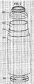
- figure 2 shows a layed structure in accordance with the invention.
- FIG. 1 shows a layed structure in accordance with the invention.
- FIG. 1 shows a layed structure in accordance with the invention.
- FIG. 1 shows a layed structure in accordance with the invention.
- FIG. 1 shows a layed structure in accordance with the invention.
- FIG. 1 shows a layed structure in accordance with the invention.
- FIG. 1 shows a layed structure in accordance with the invention.
- FIG. 1 shows a layed structure in accordance with the invention.
- the containers are comprised of porous vent materials, also called porous matrices.
- Porous matrices may be made of any of a wide variety of materials, including, but not limited to, plastics, elastomers, metals, glass, and ceramics. Combinations of plastics, elastomers, metals, glasses, or ceramics may also be used. The combinations may be intimate, such as from blending of two or more components to become co-sintered, or may be layered, such as from laminate structures derived from two or more materials. Combinations of different plastics, elastomers, metals, glasses, or ceramics can also be co-sintered or fabricated into laminate structures for use in pervaporative containers.
- thermoplastic polymers include, but are not limited to thermoplastic polymers, thermoset elastomers, and thermoplastic elastomers.
- Preferred thermoplastic polymers include, but are not limited to, low density polyethylene (LDPE), linear low density polyethylene (LLDPE), medium density polyethylene (MDPE), high-density polyethylene (HDPE), ultra-high molecular weight polyethylene (UHMWPE), polypropylene (PP) and its copolymers, polymethylpentene (PMP), polybutylene terephthalate (PBT); polyethyleneterephthalate (PET), polyethyleneterephthalate glycol modified (PETG), polyetheretherketone (PEEK), ethylenevinylacetate (EVA), polyethylenevinylalcohol (EVOH), polyacetal, polyacrylonitrile (PAN), poly(acrylonitrile-butadiene-styrene) (ABS), poly(acrylonitrile-styrene-acrylate) (AES), poly(acryloni
- thermoset elastomers include styrene-butadiene, polybutadiene (BR), ethylene-propylene, acrylonitrile-butadiene (NBR), polyisoprene, polychloroprene, silicone, fluorosilicone, urethanes, hydrogenated nitrile rubber (HNBR), polynorborene (PNR), butyl rubber (IIR) to include chlorobutyl (CIIR) and bromobutyl (BIIR), fluoroelastomers such as Viton® and Kalrez®, FluorelTM, and chlorosulfonated polyethylene.
- CIIR chlorobutyl
- BIIR bromobutyl
- fluoroelastomers such as Viton® and Kalrez®, FluorelTM, and chlorosulfonated polyethylene.
- thermoplastic elastomer (TPE) categories include thermoplastic olefins (TPO) including those commercially available as Dexflex® and Indure®; elastomeric PVC blends and alloys; styrenic block copolymers (SBC) including styrene-butadiene-styrene (SBS), styrene-isoprene-styrene (SIS), styrene-ethylene/butylene-styrene (SEBS), and styrene-ethylene-propylene-styrene (SEPS), some commercially available SBCs include those sold under the trademarks Kraton®, Dynaflex®, and ChronopreneTM; thermoplastic vulcanizate (TPV, also known as dynamically vulcanized alloys) including those commercially available under the trademarks Versalloy®, Santoprene®, and Sarlink®; thermoplastic polyurethane (TPU) including those commercially available under
- Preferred metals for porous materials include stainless steel, aluminum, zinc, copper and its alloys.
- Preferred glass and ceramics for porous materials include quartz, borosilicate, aluminosilicate, sodiumaluminosilicate, preferably in the form of sintered particles or fibers derived from said materials.
- a preferred method of making macroporous plastic is by a process called sintering, wherein powdered or granular thermoplastic polymers are subjected to the action of heat and pressure to cause partial agglomeration of the granules and formation of a cohesive macroporous sheet or part.
- the macroporous material comprises a network of interconnected macropores that form a random tortuous path through the sheet.
- the void volume or percent porosity of a macroporous sheet is from 30 to 65% depending on the conditions of sintering although it may be greater or lesser than the stated range depending on the specific method of manufacturer.
- Porous plastics including macroporous plastics, suitable for making a pervaporatively-cooled container in accordance with preferred embodiments, can be manufactured in sheets or molded to specification and is available for purchase from a number of sources. Porex Corporation (Fairburn, Georgia, U.S.A.) is one such source, and provides porous plastic under the trademark, POREX®. Porous plastic sold under the name POREX® can be purchased in sheets or molded to specification from any one of the thermoplastic polymers previously described. The average porosity of such POREX® materials can vary from about 1 to 350 microns depending on the size of polymer granules used and the conditions employed during sintering.
- GenPore® (Reading, Pennsylvania, U.S.A.) is another manufacturer of porous plastic products, with pore sizes ranging from 5 to 1000 microns.
- MA Industries Inc. (Peachtree City, Georgia, U.S.A.) also manufactures porous plastic products.
- Porvair Technology Ltd (Wrexham North Wales, U.K.) is another manufacturer of porous products supplying both porous plastic (range of 5 to 200um pore size under brand name VyonTM) and porous metal media (under brand name Sinterflo®).
- the basic size, thickness and porosity of the plastic chosen to make a pervaporative matrix may be determined by calculating the amount of vapor that must pass through the vent in a given period of time (flow rate) and the heat transfer rate from the environment back into the liquid.
- the flux rate (flow rate per unit area) of a given macroporous plastic varies depending on factors including the pore size, percent porosity, and cross sectional thickness of the matrix and is generally expressed in terms of volume per unit time per unit area.
- the flow rate of vapor through the matrix should be such that the thermodynamic heat removed from the liquid initially at room temperature due to vaporization is greater than the heat absorbed from the environment.
- the container liquid temperature cools until the heat loss of the liquid due to vaporization of the liquid contents through the matrix matches the heat gain from the surrounding environment.
- Macroporosity generally refers to the overall void volume of a material or its macrostructure.
- the term “Macroporous” is generally used to classify a material's individual pores that are considered large in size.
- the term “Microporosity” generally refers to the individual pore sizes or distribution of pore sizes that constitute the microstructure of a porous material.
- the term “Microporous” is generally used to classify a material's individual pores that are considered small in size. For purposes of the disclosure herein, pore size (diameter) is classified according to the International Union of Pure and Applied Chemistry (IUPAC) Subcommittee of Macromolecular Terminology, definitions of terms drafted on February 26, 2002.
- IUPAC International Union of Pure and Applied Chemistry
- pore size classification This standard divides pore size classification into three categories: Microporous ( ⁇ 0.002 ⁇ m), Mesoporous (0.002 to 0.050 ⁇ m) and Macroporous (>0.050 ⁇ m). Also for the purposes of this disclosure herein, void volume will be discussed in terms of the "Percent Porosity" of the material. Both macroporous as well as mesoporous materials with pore sizes of 0.05 ⁇ m or less can be used for pervaporative cooling. Preferred methods for fabrication include casting or stretching membranes of such materials.
- Preferred porous materials include those in which the pores on opposite surfaces (what will become the interior and exterior surfaces) are interconnected such that the two sides are in communication with each other. Such interconnections are preferably not, however, straight through as to create a single cylindrical tube through which material passes; instead a network of pores creates a tortuous path.
- the porous materials are preferably macroporous with pore sizes greater than or equal to 0.05 ⁇ m, preferably about 0.1 to 500 ⁇ m, and about 0.5 to 10 ⁇ m, including 0.25, 0.5, 1, 5, 15, 20, 40, 60, 80, 100, 150, 200, 250, 300, 350, 400, and 450 ⁇ m.
- the matrix materials used in conjunction with the pervaporative containers are between 0.1 and 100 ⁇ m, preferably between 0.5 and 75 ⁇ m.
- the percent porosity (percent open area) of the materials are preferably about 10 to 90%, preferably 30 to 75% or 50 to 70%, including 20%, 40%, 60%, and 80%.
- the thickness of the porous materials preferably ranges from 0.025 to 7mm, including between 1 and 3mm.
- Preferred thickness for matrix materials used in pervaporative containers are about 0.05 to 5mm and about 0.1 to 3.0mm, including 0.2, 0.3, 0.5, 0.7, 1.0, 1.25, 1.5, 1.75, 2.0, and 2.5mm.
- Other embodiments may have values for the above parameters that are above or below those set forth above.
- the material be hydrophobic or have a hydrophobic coating.
- the stated ranges include as the values contained in between the values specifically mentioned.
- materials can have one or more properties having values lying outside the disclosed ranges.
- the matrix material can be derived from plastic, elastomers, glass, metal, or combinations thereof. Some preferred matrix materials, including thermoplastic polymers, thermoset elastomers, thermoplastic elastomer, metals, glass and ceramics are as detailed above. Matrix materials may be purchased from commercial sources, or they may be made according to a variety of techniques.
- U.S. Patent No. 4,076,656 to White et a1. details one technique in which porogens are added to molten or dissolved materials, which can be leached out with a solvent, or extracted with supercritical fluids after the material sets and is in its final form.
- U.S. Patent No. 5,262,444 to Rusincovitch et al. details another technique to create porous material by introducing porogens that evolve into gases after processing a material, to leave behind a porous structure.
- pervaporative matrix materials discussed herein are hydrophobic, oleophobic pervaporative materials may also be used when the pervaporation liquid is an organic liquids such as alcohol.
- Commodity plastic materials such as nylon, polysulfone, and the cellulosics, are available in hydrophilic grades. These hydrophilic materials can be milled into particles and sintered using techniques known to those familiar in the art to produce hydrophilic porous materials with high liquid flux rates.
- Porous hydrophilic plastic, including macroporous plastic can be manufactured in sheets or molded to specification and is available for purchase from a number of sources, including Porex Corporation.
- Porous hydrophilic fiber materials can range in pore size from 20 to 120 ⁇ m with percent porosity ranging from 25 to 80 for the pore volume.
- hydrophobic porous materials can be rendered hydrophilic by one or more treatment processes familiar to those skilled in the art including, but not limited to, plasma etching, chemical etching, impregnation with wetting agents, or application of hydrophilic coatings.
- a masking process can be used in conjunction with one or more treatment processes to selectively pattern a hydrophobic porous material with regions of hydrophilicity with high liquid flux rates, if desired.
- multilayered porous constructs containing two or more layers of porous material.
- Thin layers can be laminated to make thicker layers using techniques familiar to those in the art.
- Multilayered constructs may be used to obtain a mechanical and physically superior matrix as previously observed in our tests. For instance, combining a sintered macroporous matrix of polyethylene with a thin layer of expanded PTFE on the liquid side of the container increases the hydrophobicity and liquid breakthrough pressure of water from 5 psi to over 30 psi, yet the layered matrix still maintains a similar pervaporative flux to that obtained using porous polyethylene by itself.
- Thickness of laminates preferably ranges from about 0.025 to 7000 ⁇ m with average pore sizes, percent porosity and other properties preferably as described above.
- Pervaporative matrix materials may also be derived from porous materials made from blends.
- the porous materials comprise a fluorinated resin, including, but not limited to, polyvinylfluoride (PVF), polyvinylidinefluoride (PVDF), polytetrafluoroethylene (PTFE), polyethylenetetrafluoroethylene (ETFE), fluorinated ethylene propylene (FEP), polyperfluoroalkoxyethylene (PFA), and/or fluorinated additives such as Zonyl®, blended with selected polyolefin or other resins, preferably those selected from the series of polyethylenes (LLDPE, LDPE, MDPE, HDPE, UHMWPE) polypropylene, polyesters, polycarbonates, ABS, acrylics, styrene polymethylpentene (PMP), polybutylene terephthalate (PBT); polyethyleneterephthalate (PET), polyetheretherketone (PEEK), ethylenevinylacetate (EVA)
- Elastomers may also be used alone or in blends.
- Preferred elastomers include those of the thermoset type such as styrene-butadiene, polybutadiene (BR), ethylene-propylene, acrylonitrile-butadiene (NBR), polyisoprene, polychloroprene, silicone, fluorosilicone, urethanes, hydrogenated nitrile rubber (HNBR), polynorborene (PNR), butyl rubber (IIR) to include chlorobutyl (CIIR) and bromobutyl (BIIR).
- thermoset type such as styrene-butadiene, polybutadiene (BR), ethylene-propylene, acrylonitrile-butadiene (NBR), polyisoprene, polychloroprene, silicone, fluorosilicone, urethanes, hydrogenated nitrile rubber (HNBR), polynorborene (PNR
- the resulting blends including sintered blends, have porous structures with varying amounts of porosity, flexibility and mechanical strength determined predominately from the non-PTFE or other non-fluorinated resin, and high water intrusion pressures determined predominately from the fluorinated resin due to its preferential migration to the pore surface during the sintering process.
- the percent porosity, pore size, and thickness are preferably as noted above.
- Blended matrix materials may be purchased from commercial sources, or they may be made according to a variety of techniques.
- U.S. Patent No. 5,693,273 to Wolbrom details a process of cosintering to produce multi-porosity porous plastic sheets that can be derived from two or more polymeric resin materials and U.S. Patent No.
- a pervaporative cooling system for containers that does not use any mechanical pumps to supply liquid to the pervaporative matrix surface and does not rely on a vacuum to enhance the cooling efficiency.
- the present approach utilizes a pervaporative matrix that forms part of the container, preferably the housing of the container, and comprises between about 5 to 100% of the total surface area of the container, including about 10%, 20%, 30%, 40%, 50%, 60%, 70%, 80%, and 90% of the total surface area.
- the liquid contents of the container are preferably cooled directly at the surrounding liquid/matrix interface due to the latent heat of evaporation of the liquid, such as water or a water/dissolved solid mixture or solution, in the container.
- the resulting liquid vapor is lost to the surrounding environment, in particular to an absorbent material, through the matrix.
- natural convection and conductive heat transfer within the liquid are predominant heat transfer mechanisms responsible for cooling the liquid contents of the container.
- the cooling may be substantially uniform throughout the container.
- the liquid contents of the pervaporative container or sleeve acts as a coolant.
- the liquid volume loss is marginal; for example, in one embodiment, the liquid volume loss of approximately 15% over a 24 hour time period even with significant external air circulation. Due to the high latent heat of vaporization of water (583 cal/g at 75°F), for example, approximately seven times as much weight in ice would be required to maintain the same temperature drop as a loss of water due to vaporization.
- An added benefit of the porous matrix in addition to pervaporative cooling is in venting any pressure differential developed in the container due to the release of carbonation from a beverage or due to the consumption of the contents.
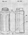
- FIG. 1A and 1B a vented pervaporative cooling container.
- the wall 501 of the container is formed at least in part of pervaporative matrix.
- This vapor permeable matrix can be from about 5 to 100% of the total surface area of the container. Approximately 100% coverage is achieved if the entire cap and housing (comprising the top 500 walls 501 and bottom 502) are made from porous matrix material.
- the pervaporative surface area is greater than about 30% of the total container surface and provides a substantial amount of pervaporative flux to effectively cool the contained liquid below ambient temperature and maintain a subambient liquid temperature.
- a multilayered construct comprising two or more layer is used.
- Three layers of porous material 503, 504 and 505 are used to obtain a multilayer or laminate matrix.
- a sintered macroporous matrix of polyethylene 505 with a thin layer of expanded PTFE 504 on the liquid side of the container increases the hydrophobicity and liquid intrusion pressure but helps to maintain a similar pervaporative flux and good mechanical stability as is obtained using porous polyethylene by itsel.
- a third layer of porous polyethylene 503 forming a sandwich with the expanded PTFE in the middle 504 provides a scratch resistance surface close to the inside of the container making it dishwasher safe and substantially preventing or reducing the soft expanded PTFE layer from being damaged.
- laminates can comprise greater or fewer than three layers and/or different porous matrix materials.
- the inner layer 503 comprises a pervaporative matrix or laminated matrix
- middle layer 504 comprises a thermally insulative material with pores or other open spaces to allow passage of the vapor
- outer layer 505 comprises a desiccant or absorbent material as defined in claim 1.
- a preferred orientation of the matrix is where a higher liquid intrusion membrane faces the inside of the container and the porous matrix support is exposed to the air outside of the container. Thicknesses for these porous materials in a preferred embodiment are in the range from about 1/1000" (0.025 mm) to 1/4" (6.4 mm).
- the porous matrices can also provide structural rigidity, scratch resistance, and/or mechanical integrity to the walls of the container.
- a membrane or thin layer of material with a small pore size can be selected from a group of highly hydrophobic materials such as expanded polytetrafluoroethylene (ePTFE) and laminated in between thicker highly porous supports such as sintered polyethylene, which allow for a substantial pervaporative flux. If only two layers are used, Each of these layers can vary in thickness from a monoatomic surface treatment to 1/4" (6.4 mm) in thickness or greater for a foam insulation or porous composite.
- ePTFE expanded polytetrafluoroethylene
- Porous ceramic materials including molecular sieves (zeolites) or porous polymer films (CSP Technologies - Auburn, Alabama) and organic matrices such as activated carbon can be used to substantially prevent or reduce odors from the environment from contaminating the liquid contents of the pervaporative cooling device or container.
- zeolites molecular sieves
- CSP Technologies - Auburn, Alabama organic matrices such as activated carbon
- a preferred layered construct comprises five layers: an inner ePTFE layer, a porous polypropylene, a thermally insulative urethane foam layer, a ceramic such as zeolite and a thin nonporous polyolefin or polyester outer wrap.
- This device can be used to maintain a pervaporative cool within the device in a humid environment. Upon absorption of the vapor released from the liquid, the zeolite or other desiccant transfers the heat directly or indirectly into the environment while the insulated liquid contents within the pervaporative sleeve are cooled.
- the outer two layers comprising zeolite and a nonporous film are disposable or regenerable such as by drying in an oven.
- the porosities of the matrices or composite are preferably maintained between about 10 to 95%. This provides for structural support within the matrix and enhances the available pervaporative surface area and hence the overall cooling rate of the container.
- the pore size of the matrix can also have an effect with Knudsen diffusion predominating below a pore size of 200 nm, effectively decreasing the vapor permeation rate and extending the liquid to vapor transition and cooling zone to the air/vapor surface of the material.
- preferred pore sizes include those between about 0.5 ⁇ m to 30 ⁇ m, which are larger than the Knudsen diffusion range.
- the liquid intrusion pressure decreases substantially above a 100 ⁇ m pore size, making the use of a single layer of macroporous material less desirable in some instances. If a combination of a membrane and a macroporous support are used, then larger pore sizes in the macroporous support become more desirable than in the absence of the combination.
- ribs 508 and 514 may be added to the inside and/or outside walls of the container to enhance the structural rigidity of the container, prevent or reduce damage to the pervaporative matrix 507 and 513 and/or provide a handhold 514.
- Figures 3C and 3F show a sports version of the ribbed design with a narrowed neck 512.
- Figure 4 shows a layer of open cell porous insulator 518 which is added to the outside surface of the container to allow for relatively unimpeded vapor diffusion out of the system but reduced convective and radiative heat flow from the surrounding environment through to the inner container walls 517 and into the liquid.
- a beneficial feature of this insulator 518 is that it aides as an additional structural support, provides a hand grip on the container and to reduce or prevent damage to the matrix 517.
- "pleated” includes rippled surfaces and other configurations for increasing surface area.
- Pleated matrices include those in which the entire surface is pleated, or in which one or more portions are pleated and others are left smooth.
- Pervaporative containers may comprise an adjustable or movable sleeve on the outside of the pervaporative matrix to allow for selective covering or uncovering of some or all of the pervaporative material. Covering some of the pervaporative material reduces the vapor flux rate is while still maintaining some pervaporative cool. Covering all substantially stops the pervaporation and can serve as a type of"on-off" switch for the container or garment.
- sleeves 524 and 525 can be provided as a means to reduce the exposed porous surface area 527 and overall evaporative cooling rate of the container and hence reduce the liquid vaporization rate and cooling rate allowing for greater control of the temperature of the container contents. Reduced cooling may be desired in some situations such as when the absolute pressure, relative humidity and/or ambient temperature are low. As shown in Figure 6B , there is preferably a separation or gap 530 between one or more portions between the container and the surrounding sleeve.
- the gap can serve as an insulating region and/or as a region of buoyant natural convective flow of vapor, allowing for the maintenance of pervaporative cooling and the minimization of radiative heat transfer to the liquid contents 529 of the container.
- the inner sleeve 524 on the outside of the porous matrix 523 of the container is preferably attached to the pervaporative matrix at least at the top 522 and bottom 526 portions of the container housing, especially if such portions are non-porous.
- a pervaporative container may comprise a pervaporative sponge which both holds water within the body of the sponge and also serves to provide cooling by pervaporation.
- a pervaporative sponge which both holds water within the body of the sponge and also serves to provide cooling by pervaporation.
- One preferred embodiment is a two-layer pervaporative sponge having an inner sponge comprising a hydrophilic material and an outer hydrophobic layer attached thereto.
- the inner sponge can be soaked with water or another vaporizable liquid prior to use and the porous hydrophobic top layer substantially prevents or reduces the leakage of the pervaporative liquid at the outer surface of the pervaporative matrix.
- the liquid provides a heat transfer path through the wet matrix directly to the inner container wall surface.
- Figure 7 illustrates a two-layer pervaporative sponge 533 that can be used on glasses, bottles and containers.
- This configuration allows the inner sponge layer 534 to be soaked with water or another vaporizable liquid and a porous hydrophobic top layer 535 substantially prevents or reduces the leakage of the liquid coolant at the outer surface of the pervaporative matrix 535.
- the liquid provides a heat transfer path through the wet matrix directly to the inner container wall surface 532.
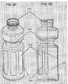
- FIG 8 shows an alternate configuration in which a cooling jacket 542 holding water or another pervaporative fluid 541 is filled through the port 543 and used to cool the contents of an enclosed container housing 539.
- the housing comprises one or more sections of pervaporative matrix 537 and optionally comprises one or more ribs 538 to enhance structural strength.
- the liquid contents 540 within the enclosed central housing 539 can thus be sealed, substantially preventing or reducing the loss of liquid volume or carbonation within this region.
- the pervaporative cooling efficiency of the container is not dependent on the nature of the enclosed liquid; it depends only on the volatility, heat of vaporization, ionic strength (tonicity) and solute content of the water or liquid 541 used to fill the surrounding housing.
- the cooling jacket may also be made of a detachable sleeve consisting of an outer hydrophobic pervaporative layer 535 and an inner porous liquid holding or absorbing layer 534.
- Figure 10 illustrates a pervaporatively-cooled drinking cup similar in function to the pervaporative bottles shown in Figures 1 A, 1B , 2 , 3 A and 3B .
- the porous matrix 555 allows the liquid to pervaporatively chill.
- the bottle housing and support ribs 556 provide structural support and insulation.
- thermodynamic feasibility of such a construction Assuming an average water vapor pervaporative flux through a porous matrix of 4*10-6 g*cm-2*s-1 at 75°F in still air from Table 1 and assuming the water vapor flux is doubled at 95°F gives 8*10-6 g*cm-2*s-1as the flux. If the enthalpy of vaporization at 95°F is 2400 J/g, then the energy dissipation per unit area of the matrix is 1.9*10-2 Watts*cm-2. In order to achieve a power dissipation of 25 Watts approximately 1500 cm2 or 1.5 ft2 of available matrix surface area needs to be used in the construction the hydration pack.
- pervaporative cooling power is a direct function of the porous surface area of the jacket.
- pervaporative cooling power is a direct function of the porous surface area of the jacket.
- approximately 150 mL of water will be spent in the process.
- a little under 0.5 lbs. of water will be used in the process.
- a water filled jacket like this may be made to weigh approximately 3 lbs or less.
- pervaporative containers including, but not limited to, sintering sub-millimeter size plastic beads in a mold cavity to directly form the pervaporation wall; thermal or ultrasonic lamination or welding of one or more pieces of pervaporative matrix together or to a suitable frame; insert molding whereby one or more sheets or a cylinder of the porous matrix is inserted into the cavity of a mold and a thermoplastic polymer is injection molded directly around the insert(s) to form the desired composite having porous matrix portions; heat sealing; attaching components using adhesives; and/or stitching techniques may also be used to assemble all or part of a pervaporative garment or container.
- Multilayered constructs containing two or more layers of porous material may be used to obtain a mechanical and physically superior matrix. For instance, combining a sintered macroporous matrix of polyethylene with a thin layer of expanded PTFE on the liquid side of a container increases the hydrophobicity and liquid breakthrough pressure of water from 5 psi to over 30 psi, yet the layered matrix still maintains a similar pervaporative flux to that obtained using porous polyethylene by itself.
- Figure 1A shows the construction of a pervaporative container with a wall portion 501 comprising pervaporative matrix.
- the wall 501 is fixed to the top 500 and bottom 502 portions of the container by a process such as by insert molding, thermal or ultrasonic welding, adhesive joining, or other suitable means. Insert injection molding may also be used to attach the matrix to the other portions of the container.
- the top of the bottle 500 illustrated in this example allows for a threaded fit and can be used with a vented bottle cap.
- the top 500 and bottom 502 portions of the container may be made by any suitable method, including injection molding, vacuum forming, and the like.
- Figures 3A and 3B show a ribbed configuration for a thin pervaporative matrix 507 for which additional structural support 508 is desired.
- the ribs 508 give the container wall both structural integrity and a ridged surface for a firmer hand grasp on the container.
- the ribs 508 can be placed on the outside, inside and/or one or more sides of the pervaporative matrix.
- the ribs 508 are preferably injection molded by insert molding onto the pervaporative matrix 507.
- ribs 508 can be sealed to a porous matrix 507 or porous matrix 507 can be sealed to a ribbed container shell 508 by ultrasonic, thermal or adhesive means, among others.
- Figures 3C and 3D demonstrate a sports version of this container which allows the container to be fixed securely in a holding bracket by the bottle neck 512.
- the mouth of the bottle 511 allows for the use of various closures, including a snap lid and threaded closure.
- Figure 4 shows a thermally insulating, hydrophobic open cell foam layer 518 that allows water vapor to move through the open cell structure, but impedes the convective and radiative heating of the container contents.
- Table 1 demonstrates that the thermally insulating matrix reduces the liquid loss rate while maintaining a substantial pervaporative cool.
- the insulating foam 518 is placed or taken off of the bottle as an elastic sleeve.
- FIG. 5 shows a pleated container body 520 that allows for a greater pervaporative surface area to be exposed per contained liquid volume. This configuration allows for a decrease in the time taken to pervaporatively cool the container volume.
- a container having this configuration can be made by insert molding or by potting both ends with adhesive to a bottom 521 and top 519 container elements or with molten plastic.
- Figures 6A and 6B demonstrate a rotating sleeve 525 on the outside of the matrix body 523.
- a set of vertical slits 527 is formed, which open and close to allow variable exposure to the pervaporative matrix 523, thereby reducing the vapor flux rate but still maintaining an adequate pervaporative cool.
- a vertical slip sleeve, whose slits are adjusted vertically instead of by rotation, may also be used in a configuration of this type.
- the inner and outer sleeves 524 and 525 are made of a substantially nonporous material such as plastic or metal that does not allow water vapor to pass.
- Figure 6B illustrates the annular sleeve which helps to maintain a very thin gap 530 between the porous matrix 523 and the inner stationary sleeve 524.
- This gap 530 is useful as a shield to substantially prevent or reduce direct conductive and radiative heat transfer to the porous matrix 523 of the main container body.
- this spacing 530 allows for vapor flux out of this annular region 527.
- the sleeves 524 and 525 may also be used over a pleated pervaporative surface 520 such as shown in Figure 5 . Again, the sleeves 524 and 525 can be placed on the outside of the container by sliding them onto the outside of the container.
- the inner sleeve 524 may be attached or sealed in place.
- FIGs 7 and 8 show jacketed pervaporative containers.
- the cooling jacket may be made of a detachable sleeve consisting of an outer hydrophobic pervaporative layer 535 and an inner porous liquid holding or absorbing layer 534.
- the outside jacket 541 is filled through special ports 543 with water or other volatile fluids 541 and the contents of the inner liquid container 540 are maintained at a sub-ambient temperature.
- One advantage to this configuration lies in that a carbonated beverage can be stored in this container without losing carbonation.
- a liquid with a low propensity to pervaporate such as a liquid high in electrolytes or sugar can be placed in the inner chamber 540 of the container while distilled water or other easily pervaporated liquid 541 is placed in the outside chamber to obtain an adequate temperature drop.
- FIG. 7 and 8 Another embodiment for a sponge 533 or jacketed 542 pervaporative configuration as shown in Figures 7 and 8 is for the use of an oleophobic pervaporative matrix which retains organic liquids such as alcohol.
- the outside jacket 533, 542 are be filled with ethanol, and serves as the pervaporative coolant 534, 541.
- Figure 10 illustrates a pervaporatively-cooled drinking cup similar in function to Figures 1A, 1B , 2 , 3A and 3B .
- Assembly may be performed wrapping a planar pervaporative matrix around or pushing the matrix 555 over the cup body 556 as a cylinder and attaching the material by adhesive, potting, thermal welding or ultrasonic welding.
- Insert molding may be used to directly attach the material into the bottle frame and walls.
- Preferred designs for pervaporative cooling devices are simple and can be operated under ambient conditions to cool and/or maintain the coolness of fluid or solid contents of the container without the weight and portability limitations associated with mechanical pumping or the need for the application of an external mechanical vacuum to increase the pervaporative cooling rate.
- the radial dimensions of a container of the type in Figure 1A are large enough such that convective mixing by natural convection of liquid contents is obtained. This is because, in some cases, the thermal conductivity of the liquid alone may not be high enough to effectively maintain a generally uniform temperature distribution throughout the container. When the liquid at the inner walls of the container are cooled, this reduces the density of the liquid at the inner walls as compared to that in the center.
- the cooler liquid flows down the inside walls of the container to the bottom of the container where it is entrained back up into a circulatory pattern within the middle of the container in a process called natural convection, as opposed to forced convection.
- convective eddies break off from the side of the container and enhance the mixing rate.
- Table 1 presents endpoint pervaporative cooling data at a relative air humidity of 30% to 41% and different ambient air velocities and the effect of a porous insulative matrix.
- Tables 2 and 3 present endpoint water pervaporative cooling data at different relative humidities and in the shade (Table 2) or in the presence of direct solar irradiation (Table 3).
- the pervaporative materials are PTFE (polytetrafluoroethylene) or sintered UHMWPE (ultra high molecular weight polyethylene).
- X-7744, X-6919, and 402HP are all UHMWPE materials of various porosity, pore size and thickness as outlined in the tables.
- Table 1 sets forth endpoint water pervaporative cooling data at different ambient air velocities and the effect of a 1/16 " open-cell porous urethane insulative matrix at a relative humidity of 30%.
- Tables 2 and 3 set forth endpoint water pervaporative cooling data at different relative humidities and in the dark or in the presence of direct solar irradiation.
- the pervaporative materials in all three tables are PTFE or sintered UHMWPE (ultra high molecular weight polyethylene).
- evaporative cooling container includes a single or combined porous matrix having a pervaporative layer thickness of about 0.025 mm (0.001 in.) to 10 mm (0.394 in.). Additionally, to increase the efficiency of the pervaporative process, the matrix preferably has qualities such that it is minimally thermally conducting. It is preferable that the matrix does not substantially impede vapor diffusion, such that, in one embodiment, a pore size above about 100 nm is preferred. Preferred surface porosities of the matrix are between about 15 and 90% including about 20, 25, 30, 35, 40, 45, 50, 55, 60, 65, 70, 75, 80, and 85%.
- a porous matrix with a low thermal conductivity such as a porous perfluorinated Styrofoam, an expanded porous matrix, or an open cell porous matrix made from hollow fused particles, can help to substantially prevent or reduce undue heat transfer from the surroundings into the container.
Landscapes
- Engineering & Computer Science (AREA)
- Mechanical Engineering (AREA)
- Health & Medical Sciences (AREA)
- General Health & Medical Sciences (AREA)
- Thermal Sciences (AREA)
- Animal Behavior & Ethology (AREA)
- Combustion & Propulsion (AREA)
- Physics & Mathematics (AREA)
- Pediatric Medicine (AREA)
- General Engineering & Computer Science (AREA)
- Life Sciences & Earth Sciences (AREA)
- Chemical & Material Sciences (AREA)
- Public Health (AREA)
- Veterinary Medicine (AREA)
- Laminated Bodies (AREA)
- Separation Using Semi-Permeable Membranes (AREA)
- Packages (AREA)
- Professional, Industrial, Or Sporting Protective Garments (AREA)
- Containers Having Bodies Formed In One Piece (AREA)
Claims (13)
- Durch Pervaporation gekühlter Behälter, umfassend:einen Behälterkörper mit einer Wand oder mehreren Wänden, wobei mindestens ein Teil der einen Wand oder der mehreren Wände eine Pervaporationsmatrix (503) aufweist, wobei die Matrix poröses hydrophobes Material umfasst, wobei die Matrix den Durchgang von geringen Mengen von Molekülen von Dampf einer flüchtigen Flüssigkeit durch die Matrix erlaubt, deren Verdampfung den Behälter kühlt, undeine Aussenschicht (505) direkt neben mindestens einem Teil des Behälterkörpers, dadurch gekennzeichnet, dass die Schicht ein Trockenmittel- oder absorbierendes Material aufweist, das Feuchtigkeit oder anderes Fluid absorbiert, das aus der Pervaporation resultiert, wobei die Aussenschicht (505) zum Wegwerfen oder separat wiederverwendbar, beispielsweise durch Trocknen in einem Ofen, ist.
- Durch Pervaporation gekühlter Behälter nach Anspruch 1, wobei die Matrix ferner ein dünnes hydrophobes oder oleophobes poröses Material umfasst, das auf das poröse hydrophobe Material laminiert oder auf dem porösen hydrophoben Material abgeschieden ist.
- Durch Pervaporation gekühlter Behälter nach Anspruch 2, wobei die Matrix auf dem Behälterkörper so angeordnet ist, dass die Schicht von porösem hydrophoben Material dem Inneren des Behälters gegenübersteht.
- Durch Pervaporation gekühlter Behälter nach Anspruch 1, wobei mindestens 10% der Oberfläche der einen Wand oder der mehreren Wände die Matrix aufweisen.
- Durch Pervaporation gekühlter Behälter nach Anspruch 1, der ferner eine Basis (502) aufweist, die an der einen Wand oder den mehreren Wänden angebracht ist.
- Durch Pervaporation gekühlter Behälter nach Anspruch 1, wobei die Matrix eine Innenschicht umfasst, die ein hoch hydrophobes poröses Material umfasst, dass zwischen zwei Aussenschichten von porösem hydrophoben Material plaziert ist.
- Durch Pervaporation gekühlter Behälter nach Anspruch 6, wobei die Innenschicht eine Porengröße und -dicke kleiner als die der Aussenschichten hat.
- Durch Pervaporation gekühlter Behälter nach Anspruch 6, wobei die Innenschicht PTFE umfasst und die Aussenschicht Polyethylen umfasst.
- Durch Pervaporation gekühlter Behälter nach Anspruch 1, wobei der Behälter ferner eine Mehrzahl von Trägerlamellen (508, 514) umfasst.
- Durch Pervaporation gekühlter Behälter nach Anspruch 1, wobei die Matrix (503) aus hohlen oder expandierten Teilchen zusammengesetzt ist, die miteinander verschmolzen oder verklebt sind, um die Wärmeleitfähigkeit der Matrix und den Verlust von Pervaporationskühlungswirksamkeit zu vermindern.
- Durch Pervaporation gekühlter Behälter nach Anspruch 1, der ferner einen Isolierärmel (518) umfasst, der mindestens einen Teil der einen Wand oder der mehreren Wände umgibt.
- Durch Pervaporation gekühlter Behälter nach Anspruch 11, wobei der Isolierärmel (518) ein poröses Material umfasst.
- Durch Pervaporation gekühlter Behälter nach Anspruch 11, wobei der Isolierärmel (518) im Allgemeinen röhrenförmig ist und ein oder mehrere Öffnungen in seiner Wand hat, wodurch der Ärmel um den Behälter gedreht werden kann, um Bereiche der Pervaporationsmatrix selektiv zu bedecken oder freizulegen.
Applications Claiming Priority (7)
| Application Number | Priority Date | Filing Date | Title |
|---|---|---|---|
| US38860902P | 2002-06-03 | 2002-06-03 | |
| US388609P | 2002-06-03 | ||
| US40435502P | 2002-08-16 | 2002-08-16 | |
| US404355P | 2002-08-16 | ||
| US45805403P | 2003-03-25 | 2003-03-25 | |
| US458054P | 2003-03-25 | ||
| PCT/US2003/017544 WO2003102480A2 (en) | 2002-06-03 | 2003-06-03 | Pervaporatively cooled containers |
Publications (2)
| Publication Number | Publication Date |
|---|---|
| EP1549890A2 EP1549890A2 (de) | 2005-07-06 |
| EP1549890B1 true EP1549890B1 (de) | 2009-08-12 |
Family
ID=29716154
Family Applications (1)
| Application Number | Title | Priority Date | Filing Date |
|---|---|---|---|
| EP03734378A Expired - Lifetime EP1549890B1 (de) | 2002-06-03 | 2003-06-03 | Pervaporativ gekühlte behälter |
Country Status (8)
| Country | Link |
|---|---|
| EP (1) | EP1549890B1 (de) |
| JP (2) | JP3957715B2 (de) |
| AT (1) | ATE439561T1 (de) |
| AU (1) | AU2003239965B2 (de) |
| CA (1) | CA2488438A1 (de) |
| DE (1) | DE60328805D1 (de) |
| MX (1) | MXPA04012152A (de) |
| WO (1) | WO2003102480A2 (de) |
Families Citing this family (9)
| Publication number | Priority date | Publication date | Assignee | Title |
|---|---|---|---|---|
| WO2004049846A2 (en) * | 2002-12-03 | 2004-06-17 | Silver Eagle Outfitters Llc | Personal hydration and cooling system |
| AU2003903746A0 (en) * | 2003-07-18 | 2003-07-31 | Rmit University | Cooling garment |
| ES2264318B1 (es) * | 2004-03-22 | 2007-11-16 | Thierry Jacques Drugeon | Cubierta para envase. |
| US7565705B2 (en) * | 2004-05-11 | 2009-07-28 | Biocool Technologies, Llc | Garment for a cooling and hydration system |
| US8308013B2 (en) | 2009-03-27 | 2012-11-13 | Oberweis Dairy, Inc. | System and method for holding a hazardous substance |
| FR2975383A1 (fr) * | 2011-05-19 | 2012-11-23 | Jean Marc Pascal | Dispositif permettant d'ameliorer la conservation et le gout de l'eau et des denrees alimentaires pour les populations des pays chauds |
| WO2020205264A1 (en) | 2019-03-29 | 2020-10-08 | Gen-Probe Incorporated | Disposable pipette tip management |
| KR20220048358A (ko) * | 2020-10-12 | 2022-04-19 | 주식회사 써모랩코리아 | 전자종이 디스플레이 패널을 포함하는 패키징 시스템 |
| WO2022080595A1 (ko) | 2020-10-12 | 2022-04-21 | 주식회사 써모랩코리아 | 리터너블 패키징 및 패키징의 상태정보를 활용한 신선제품 배송 시스템 |
Family Cites Families (6)
| Publication number | Priority date | Publication date | Assignee | Title |
|---|---|---|---|---|
| JPS6229901Y2 (de) * | 1979-12-24 | 1987-07-31 | ||
| US4380157A (en) * | 1981-07-08 | 1983-04-19 | Peter Christiani | Self-chilling dispenser for drinking fluids |
| CH658901A5 (en) * | 1985-12-17 | 1986-12-15 | Antoine Dubas | Cooling box with evaporation |
| DE3902233C2 (de) * | 1989-01-26 | 1994-04-14 | Walter Dr Koecher | Beutelförmige Kühlvorrichtung |
| US5946931A (en) * | 1998-02-25 | 1999-09-07 | The United States Of America As Represented By The Administrator Of The National Aeronautics And Space Administration | Evaporative cooling membrane device |
| US6676993B2 (en) * | 1999-02-12 | 2004-01-13 | Bha Technologies, Inc. | Porous membrane structure and method |
-
2003
- 2003-06-03 EP EP03734378A patent/EP1549890B1/de not_active Expired - Lifetime
- 2003-06-03 AT AT03734378T patent/ATE439561T1/de not_active IP Right Cessation
- 2003-06-03 WO PCT/US2003/017544 patent/WO2003102480A2/en not_active Ceased
- 2003-06-03 AU AU2003239965A patent/AU2003239965B2/en not_active Ceased
- 2003-06-03 DE DE60328805T patent/DE60328805D1/de not_active Expired - Fee Related
- 2003-06-03 MX MXPA04012152A patent/MXPA04012152A/es active IP Right Grant
- 2003-06-03 JP JP2004509324A patent/JP3957715B2/ja not_active Expired - Fee Related
- 2003-06-03 CA CA002488438A patent/CA2488438A1/en not_active Abandoned
-
2007
- 2007-02-08 JP JP2007029510A patent/JP2007198728A/ja active Pending
Also Published As
| Publication number | Publication date |
|---|---|
| DE60328805D1 (de) | 2009-09-24 |
| MXPA04012152A (es) | 2005-07-29 |
| WO2003102480A3 (en) | 2004-04-15 |
| WO2003102480A8 (en) | 2004-07-29 |
| JP2005528576A (ja) | 2005-09-22 |
| AU2003239965B2 (en) | 2007-10-25 |
| WO2003102480A2 (en) | 2003-12-11 |
| ATE439561T1 (de) | 2009-08-15 |
| CA2488438A1 (en) | 2003-12-11 |
| AU2003239965A1 (en) | 2003-12-19 |
| JP3957715B2 (ja) | 2007-08-15 |
| EP1549890A2 (de) | 2005-07-06 |
| JP2007198728A (ja) | 2007-08-09 |
Similar Documents
| Publication | Publication Date | Title |
|---|---|---|
| US7107783B2 (en) | Self-cooling containers for liquids | |
| US7475560B2 (en) | Cooling tubes and straws for liquids | |
| KR100768072B1 (ko) | 투과증발식 냉각용기 | |
| EP1549890B1 (de) | Pervaporativ gekühlte behälter | |
| US8545973B2 (en) | Sealable containers | |
| US7896199B2 (en) | Portable liquid-dispensing bag | |
| US11312640B2 (en) | Method and device for enhanced water production in solar-powered devices | |
| JP2008239172A (ja) | 断熱容器及びその製造方法 | |
| US20150083727A1 (en) | Sealable containers | |
| CN103300673B (zh) | 能速冷的保温杯 | |
| RU2291361C2 (ru) | Контейнеры, охлаждаемые за счет диффузионного испарения | |
| CN106457121B (zh) | 气体吸附器件和使用该气体吸附器件的真空隔热件 | |
| HK1079275A (en) | Pervaporatively cooled containers | |
| HK1116335A2 (zh) | 热交换器和具有热交换器的调温容器 | |
| JPS6255820B2 (de) | ||
| KR0159717B1 (ko) | 부직포로 충진한 진공 단열재의 제조방법 | |
| US12098880B1 (en) | Apparatus for chilling beverages and other food products and process of manufacture | |
| CN211049096U (zh) | 一种电热水杯 | |
| US20120186285A1 (en) | Drinking water cooler | |
| ES1073051U (es) | Recipiente auto-refrigerante. | |
| CN111619163A (zh) | 以均温挤压成型系统制作防止墨料污染包装材料的方法 | |
| HK1077796A (en) | Vented closures for containers | |
| JPH028898B2 (de) |
Legal Events
| Date | Code | Title | Description |
|---|---|---|---|
| PUAI | Public reference made under article 153(3) epc to a published international application that has entered the european phase |
Free format text: ORIGINAL CODE: 0009012 |
|
| 17P | Request for examination filed |
Effective date: 20041221 |
|
| AK | Designated contracting states |
Kind code of ref document: A2 Designated state(s): AT BE BG CH CY CZ DE DK EE ES FI FR GB GR HU IE IT LI LU MC NL PT RO SE SI SK TR |
|
| AX | Request for extension of the european patent |
Extension state: AL LT LV MK |
|
| DAX | Request for extension of the european patent (deleted) | ||
| 17Q | First examination report despatched |
Effective date: 20060904 |
|
| GRAP | Despatch of communication of intention to grant a patent |
Free format text: ORIGINAL CODE: EPIDOSNIGR1 |
|
| GRAS | Grant fee paid |
Free format text: ORIGINAL CODE: EPIDOSNIGR3 |
|
| GRAA | (expected) grant |
Free format text: ORIGINAL CODE: 0009210 |
|
| AK | Designated contracting states |
Kind code of ref document: B1 Designated state(s): AT BE BG CH CY CZ DE DK EE ES FI FR GB GR HU IE IT LI LU MC NL PT RO SE SI SK TR |
|
| REG | Reference to a national code |
Ref country code: GB Ref legal event code: FG4D |
|
| REG | Reference to a national code |
Ref country code: CH Ref legal event code: EP |
|
| REG | Reference to a national code |
Ref country code: IE Ref legal event code: FG4D |
|
| REF | Corresponds to: |
Ref document number: 60328805 Country of ref document: DE Date of ref document: 20090924 Kind code of ref document: P |
|
| PG25 | Lapsed in a contracting state [announced via postgrant information from national office to epo] |
Ref country code: FI Free format text: LAPSE BECAUSE OF FAILURE TO SUBMIT A TRANSLATION OF THE DESCRIPTION OR TO PAY THE FEE WITHIN THE PRESCRIBED TIME-LIMIT Effective date: 20090812 Ref country code: AT Free format text: LAPSE BECAUSE OF FAILURE TO SUBMIT A TRANSLATION OF THE DESCRIPTION OR TO PAY THE FEE WITHIN THE PRESCRIBED TIME-LIMIT Effective date: 20090812 Ref country code: SE Free format text: LAPSE BECAUSE OF FAILURE TO SUBMIT A TRANSLATION OF THE DESCRIPTION OR TO PAY THE FEE WITHIN THE PRESCRIBED TIME-LIMIT Effective date: 20090812 Ref country code: ES Free format text: LAPSE BECAUSE OF FAILURE TO SUBMIT A TRANSLATION OF THE DESCRIPTION OR TO PAY THE FEE WITHIN THE PRESCRIBED TIME-LIMIT Effective date: 20091123 |
|
| NLV1 | Nl: lapsed or annulled due to failure to fulfill the requirements of art. 29p and 29m of the patents act | ||
| PG25 | Lapsed in a contracting state [announced via postgrant information from national office to epo] |
Ref country code: NL Free format text: LAPSE BECAUSE OF FAILURE TO SUBMIT A TRANSLATION OF THE DESCRIPTION OR TO PAY THE FEE WITHIN THE PRESCRIBED TIME-LIMIT Effective date: 20090812 Ref country code: SI Free format text: LAPSE BECAUSE OF FAILURE TO SUBMIT A TRANSLATION OF THE DESCRIPTION OR TO PAY THE FEE WITHIN THE PRESCRIBED TIME-LIMIT Effective date: 20090812 |
|
| PG25 | Lapsed in a contracting state [announced via postgrant information from national office to epo] |
Ref country code: PT Free format text: LAPSE BECAUSE OF FAILURE TO SUBMIT A TRANSLATION OF THE DESCRIPTION OR TO PAY THE FEE WITHIN THE PRESCRIBED TIME-LIMIT Effective date: 20091212 Ref country code: BG Free format text: LAPSE BECAUSE OF FAILURE TO SUBMIT A TRANSLATION OF THE DESCRIPTION OR TO PAY THE FEE WITHIN THE PRESCRIBED TIME-LIMIT Effective date: 20091112 |
|
| PG25 | Lapsed in a contracting state [announced via postgrant information from national office to epo] |
Ref country code: RO Free format text: LAPSE BECAUSE OF FAILURE TO SUBMIT A TRANSLATION OF THE DESCRIPTION OR TO PAY THE FEE WITHIN THE PRESCRIBED TIME-LIMIT Effective date: 20090812 Ref country code: EE Free format text: LAPSE BECAUSE OF FAILURE TO SUBMIT A TRANSLATION OF THE DESCRIPTION OR TO PAY THE FEE WITHIN THE PRESCRIBED TIME-LIMIT Effective date: 20090812 Ref country code: DK Free format text: LAPSE BECAUSE OF FAILURE TO SUBMIT A TRANSLATION OF THE DESCRIPTION OR TO PAY THE FEE WITHIN THE PRESCRIBED TIME-LIMIT Effective date: 20090812 Ref country code: CZ Free format text: LAPSE BECAUSE OF FAILURE TO SUBMIT A TRANSLATION OF THE DESCRIPTION OR TO PAY THE FEE WITHIN THE PRESCRIBED TIME-LIMIT Effective date: 20090812 |
|
| PG25 | Lapsed in a contracting state [announced via postgrant information from national office to epo] |
Ref country code: SK Free format text: LAPSE BECAUSE OF FAILURE TO SUBMIT A TRANSLATION OF THE DESCRIPTION OR TO PAY THE FEE WITHIN THE PRESCRIBED TIME-LIMIT Effective date: 20090812 |
|
| PLBE | No opposition filed within time limit |
Free format text: ORIGINAL CODE: 0009261 |
|
| STAA | Information on the status of an ep patent application or granted ep patent |
Free format text: STATUS: NO OPPOSITION FILED WITHIN TIME LIMIT |
|
| PG25 | Lapsed in a contracting state [announced via postgrant information from national office to epo] |
Ref country code: BE Free format text: LAPSE BECAUSE OF FAILURE TO SUBMIT A TRANSLATION OF THE DESCRIPTION OR TO PAY THE FEE WITHIN THE PRESCRIBED TIME-LIMIT Effective date: 20090812 |
|
| 26N | No opposition filed |
Effective date: 20100517 |
|
| PG25 | Lapsed in a contracting state [announced via postgrant information from national office to epo] |
Ref country code: GR Free format text: LAPSE BECAUSE OF FAILURE TO SUBMIT A TRANSLATION OF THE DESCRIPTION OR TO PAY THE FEE WITHIN THE PRESCRIBED TIME-LIMIT Effective date: 20091113 |
|
| PG25 | Lapsed in a contracting state [announced via postgrant information from national office to epo] |
Ref country code: MC Free format text: LAPSE BECAUSE OF NON-PAYMENT OF DUE FEES Effective date: 20100630 |
|
| REG | Reference to a national code |
Ref country code: CH Ref legal event code: PL |
|
| GBPC | Gb: european patent ceased through non-payment of renewal fee |
Effective date: 20100603 |
|
| REG | Reference to a national code |
Ref country code: FR Ref legal event code: ST Effective date: 20110228 |
|
| PG25 | Lapsed in a contracting state [announced via postgrant information from national office to epo] |
Ref country code: IT Free format text: LAPSE BECAUSE OF FAILURE TO SUBMIT A TRANSLATION OF THE DESCRIPTION OR TO PAY THE FEE WITHIN THE PRESCRIBED TIME-LIMIT Effective date: 20090812 |
|
| PG25 | Lapsed in a contracting state [announced via postgrant information from national office to epo] |
Ref country code: CH Free format text: LAPSE BECAUSE OF NON-PAYMENT OF DUE FEES Effective date: 20100630 Ref country code: LI Free format text: LAPSE BECAUSE OF NON-PAYMENT OF DUE FEES Effective date: 20100630 Ref country code: DE Free format text: LAPSE BECAUSE OF NON-PAYMENT OF DUE FEES Effective date: 20110101 Ref country code: IE Free format text: LAPSE BECAUSE OF NON-PAYMENT OF DUE FEES Effective date: 20100603 |
|
| PG25 | Lapsed in a contracting state [announced via postgrant information from national office to epo] |
Ref country code: FR Free format text: LAPSE BECAUSE OF NON-PAYMENT OF DUE FEES Effective date: 20100630 |
|
| PG25 | Lapsed in a contracting state [announced via postgrant information from national office to epo] |
Ref country code: GB Free format text: LAPSE BECAUSE OF NON-PAYMENT OF DUE FEES Effective date: 20100603 |
|
| PG25 | Lapsed in a contracting state [announced via postgrant information from national office to epo] |
Ref country code: CY Free format text: LAPSE BECAUSE OF FAILURE TO SUBMIT A TRANSLATION OF THE DESCRIPTION OR TO PAY THE FEE WITHIN THE PRESCRIBED TIME-LIMIT Effective date: 20090812 |
|
| PG25 | Lapsed in a contracting state [announced via postgrant information from national office to epo] |
Ref country code: LU Free format text: LAPSE BECAUSE OF NON-PAYMENT OF DUE FEES Effective date: 20100603 Ref country code: HU Free format text: LAPSE BECAUSE OF FAILURE TO SUBMIT A TRANSLATION OF THE DESCRIPTION OR TO PAY THE FEE WITHIN THE PRESCRIBED TIME-LIMIT Effective date: 20100213 |
|
| PG25 | Lapsed in a contracting state [announced via postgrant information from national office to epo] |
Ref country code: TR Free format text: LAPSE BECAUSE OF FAILURE TO SUBMIT A TRANSLATION OF THE DESCRIPTION OR TO PAY THE FEE WITHIN THE PRESCRIBED TIME-LIMIT Effective date: 20090812 |