EP1549874B1 - Drehverbindungssystem - Google Patents
Drehverbindungssystem Download PDFInfo
- Publication number
- EP1549874B1 EP1549874B1 EP03780212A EP03780212A EP1549874B1 EP 1549874 B1 EP1549874 B1 EP 1549874B1 EP 03780212 A EP03780212 A EP 03780212A EP 03780212 A EP03780212 A EP 03780212A EP 1549874 B1 EP1549874 B1 EP 1549874B1
- Authority
- EP
- European Patent Office
- Prior art keywords
- conduit
- swivel joint
- annular
- cryogenic liquid
- passage
- Prior art date
- Legal status (The legal status is an assumption and is not a legal conclusion. Google has not performed a legal analysis and makes no representation as to the accuracy of the status listed.)
- Expired - Lifetime
Links
- 239000007789 gas Substances 0.000 claims abstract description 21
- 239000007788 liquid Substances 0.000 claims abstract description 13
- 239000003949 liquefied natural gas Substances 0.000 claims abstract description 10
- 238000007789 sealing Methods 0.000 claims description 7
- 239000004809 Teflon Substances 0.000 claims description 2
- 229920006362 Teflon® Polymers 0.000 claims description 2
- 230000000694 effects Effects 0.000 claims description 2
- 239000011810 insulating material Substances 0.000 claims description 2
- 239000003566 sealing material Substances 0.000 claims 1
- 238000009413 insulation Methods 0.000 description 2
- 230000007123 defense Effects 0.000 description 1
- 230000001419 dependent effect Effects 0.000 description 1
- -1 for example Substances 0.000 description 1
- 239000000463 material Substances 0.000 description 1
- 238000012986 modification Methods 0.000 description 1
- 230000004048 modification Effects 0.000 description 1
- 230000000717 retained effect Effects 0.000 description 1
- 238000005096 rolling process Methods 0.000 description 1
- 229910001220 stainless steel Inorganic materials 0.000 description 1
- 239000010935 stainless steel Substances 0.000 description 1
Images


Classifications
-
- F—MECHANICAL ENGINEERING; LIGHTING; HEATING; WEAPONS; BLASTING
- F16—ENGINEERING ELEMENTS AND UNITS; GENERAL MEASURES FOR PRODUCING AND MAINTAINING EFFECTIVE FUNCTIONING OF MACHINES OR INSTALLATIONS; THERMAL INSULATION IN GENERAL
- F16L—PIPES; JOINTS OR FITTINGS FOR PIPES; SUPPORTS FOR PIPES, CABLES OR PROTECTIVE TUBING; MEANS FOR THERMAL INSULATION IN GENERAL
- F16L39/00—Joints or fittings for double-walled or multi-channel pipes or pipe assemblies
- F16L39/04—Joints or fittings for double-walled or multi-channel pipes or pipe assemblies allowing adjustment or movement
-
- F—MECHANICAL ENGINEERING; LIGHTING; HEATING; WEAPONS; BLASTING
- F16—ENGINEERING ELEMENTS AND UNITS; GENERAL MEASURES FOR PRODUCING AND MAINTAINING EFFECTIVE FUNCTIONING OF MACHINES OR INSTALLATIONS; THERMAL INSULATION IN GENERAL
- F16L—PIPES; JOINTS OR FITTINGS FOR PIPES; SUPPORTS FOR PIPES, CABLES OR PROTECTIVE TUBING; MEANS FOR THERMAL INSULATION IN GENERAL
- F16L59/00—Thermal insulation in general
- F16L59/14—Arrangements for the insulation of pipes or pipe systems
- F16L59/16—Arrangements specially adapted to local requirements at flanges, junctions, valves or the like
- F16L59/18—Arrangements specially adapted to local requirements at flanges, junctions, valves or the like adapted for joints
- F16L59/185—Adjustable joints; Joints allowing movement
-
- Y—GENERAL TAGGING OF NEW TECHNOLOGICAL DEVELOPMENTS; GENERAL TAGGING OF CROSS-SECTIONAL TECHNOLOGIES SPANNING OVER SEVERAL SECTIONS OF THE IPC; TECHNICAL SUBJECTS COVERED BY FORMER USPC CROSS-REFERENCE ART COLLECTIONS [XRACs] AND DIGESTS
- Y10—TECHNICAL SUBJECTS COVERED BY FORMER USPC
- Y10S—TECHNICAL SUBJECTS COVERED BY FORMER USPC CROSS-REFERENCE ART COLLECTIONS [XRACs] AND DIGESTS
- Y10S285/00—Pipe joints or couplings
- Y10S285/904—Cryogenic
Definitions
- the invention relates to a rotary joint system according to the preamble of claim 1.
- a system of this type is already known from European Patent No. 0188161 .
- the two rotating joint devices for the passage of the cryogenic liquid and the return of the gas are made in the form of independent devices, the conduit for the passage of the gas return concentrically surrounding the fixed conduit portion of the seal device for the passage of the cryogenic liquid, with a thermal insulation layer interposed between the two concentric ducts.
- This rotating seal system has the disadvantage of having a complex structure and be bulky.
- the object of the present invention is to propose a rotary joint system which overcomes this disadvantage.
- the rotary joint system according to the invention has the features which are set forth in claim 1.
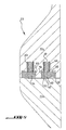
- the figure 1 illustrates, by way of example of an application of the invention, the use of a rotary joint system according to the invention in an offshore station for the transfer of liquefied natural gas from a moored vessel to this station and a storage station remote from the offshore station.
- the offshore station has a column 2 which rests on the seabed and whose head 3 is likely to rotate about the axis of the column.
- This head carries a boom 4 at the free end of which is suspended a gas transfer hose liquefied natural gas and another gas return hose whose other ends are likely to be connected to the manifold of the transport vessel.
- a gas transfer hose liquefied natural gas
- another gas return hose whose other ends are likely to be connected to the manifold of the transport vessel.
- the figure 1 we see in 6 a mooring ring of the ship via a hawser 10 which is integral with the rotating head 3.
- the figure 1 shows a circular defense surrounding the column.
- a rotary joint system according to the invention, designated by the reference A. This seal system is mounted in the transfer piping liquefied natural gas 8 and the conduit 9 of the gas return.
- the rotary joint system A comprises a central conduit 12 for the passage of liquefied natural gas, which is connected up and down to the transfer piping provided inside the column 2 of the offshore station 1.
- the connection of the seal system piping 8 is up and down with screws 14, as seen in particular on Figures 3 and 4 , with the interposition of an annular seal 15 between the end flanges 13a, 13b, 15a, 15b of the seal system and the pipes.
- the central duct 12 comprises a lower duct section 12a which is fixedly mounted inside the column and an upper section 12b which is rotatably mounted relative to the fixed lower section 12b. Between the two end faces opposite respectively 20 and 21 of the fixed 12a and rotary 12b sections is provided a suitable seal 23 which allows a significant relative annular movement of the two sections 12a and 12b.
- a suitable seal 23 which allows a significant relative annular movement of the two sections 12a and 12b.
- Around the central duct 12 is provided, coaxially with the latter, an annular space 25, which is delimited radially internally by the central duct 12 and radially externally by a wall 29.
- the wall 29 extends between the two flanges 13a, 13b.
- the space 25 which is thus closed at the top and at the bottom constitutes the gas return duct which enters the space 25 via an inlet lateral connection piece 27 and leaves this space via an outlet lateral connection piece 28.
- the gas return duct, formed by the space 25, comprises a lower part 25a which coaxially surrounds the fixed lower section 12a of the central duct 12, being integral with it, and an upper part 25b which coaxially surrounds the rotary upper section. 12b of the central duct 12 being integral with this section. Therefore, the upper part 25b is rotatable relative to the lower part 25a of the gas return space-conduit 25. Between the two parts 25a and 25b, in the outer wall 29 is provided, between the facing end faces 34 and a seal 37 which will be described in more detail later
- the two seals 23 and 37 respectively belonging to the central conduit 12 for passing liquefied natural gas and to the gas return conduit 25 are in parallel planes but axially offset.
- the assembly formed by the central duct 12 and the wall 29 surrounding it coaxially forming the ducted space 25 is surrounded by an outer jacket 39 which extends coaxially between the upper and lower flanges 13b 13a and is divided in two portions, a fixed lower portion 39a and an upper rotary portion 39b.
- the facing free ends 41, 42, in the form of flanges, of the sleeve 39 carry a rotational guiding device in the form of a roller orientation ring, such as for example a rotational bearing 44 which is arranged by example in the P2 plane of the seal 37 of the space-conduit 25 of gas return.
- the rolling bearing which forms a device for mechanically guiding the two parts of the seal system A, can be of any suitable known nature, for example with pebbles or balls.
- revolution members are disposed between a bearing portion 45 fixed by screws 46 to the flange-shaped end 41 of the fixed lower liner portion 39a and a portion 48 retained by screws 49 at the free end 42 of the upper rotating sleeve portion 39b.
- each partial space 50a and 50b is for example filled with a block made of a thermally insulating material 52a, 52b, the two opposite faces of the two blocks being adapted to slide on one another during an angular movement of the mobile part of the seal relative to the fixed part.
- the faces in contact have a stepped profile.
- the single rotation bearing which equips the rotary joint system according to the invention is at the outer periphery and can therefore work at a temperature close to ambient temperature, and therefore not cryogenic.
- the seals 23, 37 are configured to be able to absorb large radial and axial movements and can be made as shown in FIG. figure 5 .
- the seal shown by way of example comprises two ring 54, 55 of a suitable material such as, for example, Teflon, which are each received in a groove 57, 58 formed in the end face 21 of the central pipe section 12b.
- the grooves 57, 58 are concentric.
- Each sealing ring 54, 55 has on its face facing the front face 20 of the central pipe section 12a a protruding portion 60 whose front face is clamped against the face 20 under the effect of a spring 63 which is interposed between the rear face 65 of the ring and the bottom 67 of the groove 57, 58 for receiving the sealing ring.
- cylindrical inlet and outlet connector ends 27, 28 of the gas return duct pass through circular openings 69 formed in the outer casing 39.
- the structure of the rotary joint 1 according to the invention is made of stainless steel of the AISI 316 L type and can be arranged with a vertical or horizontal axis of rotation.
- the rotary joint system according to the invention therefore has the advantages of a common wall of the coaxial joint devices, made possible by a merged architecture in the form of a single homogeneous module comprising a single "hot” mechanism and thus "standard” which is reliable over time and can withstand the efforts of the pipes.
- the common wall makes it possible not to place thermal insulation between the liquefied natural gas and the vapor gas and this neither in gas circuit nor in vapor circuit.
Landscapes
- Engineering & Computer Science (AREA)
- General Engineering & Computer Science (AREA)
- Mechanical Engineering (AREA)
- Joints Allowing Movement (AREA)
- Filling Or Discharging Of Gas Storage Vessels (AREA)
- Quick-Acting Or Multi-Walled Pipe Joints (AREA)
- Thermal Insulation (AREA)
- Radiation-Therapy Devices (AREA)
- Nonmetallic Welding Materials (AREA)
Claims (7)
- Drehverbindungssystem, dazu ausgelegt, in einer Linie zur Übertragung einer cryogenen Flüssigkeit wie z.B. verflüssigtem Erdgas und zur Rückführung von kaltem Gas, verbunden mit der Übertragung der cryogenen Flüssigkeit, montiert zu sein, des Typs umfassend eine Drehverbindungsvorrichtung für den Durchgang der cryogenen Flüssigkeit und eine Drehverbindungsvorrichtung für die Rückführung des kalten Gases, wobei jede Vorrichtung einen Kanal umfasst, der mit einem festen Kanalteil und einem drehenden Kanalteil mit Bezug auf den festen Kanalteil und Mitteln zur drehenden Führung versehen ist, die zwischen den zwei Kanalteilen angebracht sind, dadurch gekennzeichnet, dass die Drehverbindungsvorrichtung für den Durchgang der Rückführung des Gases in die Drehverbindungsvorrichtung für den Durchgang der cryogenen Flüssigkeit integriert ist, und dadurch, dass sie eine einzige und gleiche Vorrichtung zur drehenden Führung umfasst, wie z.B. ein Wälzlager (44) für die zwei Vorrichtungen.
- System nach Anspruch 1, dadurch gekennzeichnet, dass es einen zentralen Kanal (12) zum Durchgang der cryogenen Flüssigkeit und einen ringförmigen Kanal zur Rückführung des kalten Gases (25) umfasst, koaxial umgebend den zentralen Kanal (12) und eine äußere Umhüllung (39), koaxial zum zentralen Kanal, zwischen zwei Endflanschen (13a, 13b), und dadurch, dass der zentrale (12) und der ringförmige (29) Kanal und die äußere Umhüllung (39) in zwei axial ausgerichteten Stücken durchgeführt sind, die in Bezug aufeinander drehbar sind, und dadurch, dass das Wälzlager (44) zwischen den zwei Seiten gegenüber den zwei Teilen der Umhüllung angebracht ist, während eine Dichtung (23, 37) zwischen den Seiten gegenüber den zwei Stücken des zentralen und des ringförmigen Kanals angebracht sind, wobei das Wälzlager und die Dichtungen auf mindestens parallelen Ebenen (P1, P2) angebracht sind.
- System nach Anspruch 2, dadurch gekennzeichnet, dass der ringförmige Raum (50), der zwischen dem ringförmigen Kanal (29) und der äußeren Umhüllung (39) begrenzt ist, mit einem thermisch isolierenden Material gefüllt ist, vorteilhafterweise konfiguriert in zwei Blöcken (52a, 52b), die jeweils in einem der zwei oben angegebenen festen und drehenden Teile der Verbindung angebracht sind, wobei die zwei Blöcke (52a, 52b) eine Drehbewegung des einen mit Bezug auf den anderen ermöglichen.
- System nach einem der Ansprüche 1 bis 3, dadurch gekennzeichnet, dass die radiale Innenwand des ringförmigen Kanals (29) zur Rückführung des kalten Gases durch die Wand des zentralen Kanals (12) des Durchgangs der cryogenen Flüssigkeit gebildet ist.
- System nach Anspruch 4, dadurch gekennzeichnet, dass es zwei Dichtungen (23, 37) umfasst, wobei die eine (23) im zentralen Kanal (12) und die andere (27) in der Außenwand (29) zur Begrenzung des ringförmigen Kanals angebracht ist.
- System nach Anspruch 5, dadurch gekennzeichnet, dass eine Dichtung (23, 37) zwei Ringe aus einem Dichtungsmaterial wie z.B. Teflon umfasst, die konzentrisch in einer der Seiten gegenüber den entsprechenden Teilen des Kanals angebracht sind und gegen die andere Seite unter der Einwirkung eines Organs wie z.B. einer Feder gedrückt werden.
- System nach einem der Ansprüche 3 bis 6, dadurch gekennzeichnet, dass der zentrale Kanal (12) und der ringförmige Kanal (29), die koaxial sind, eine gemeinsame Wand aufweisen.
Applications Claiming Priority (3)
| Application Number | Priority Date | Filing Date | Title |
|---|---|---|---|
| FR0212694A FR2845753B1 (fr) | 2002-10-11 | 2002-10-11 | Systeme de joint tournant destine a etre monte dans une ligne de transfert d'un liquide cryogenique, tel que du gaz naturel liquefie, et du retour de gaz froid lie au transfert du liquide cryogenique |
| FR0212694 | 2002-10-11 | ||
| PCT/FR2003/003005 WO2004033950A1 (fr) | 2002-10-11 | 2003-10-10 | Systeme de joint tournant |
Publications (2)
| Publication Number | Publication Date |
|---|---|
| EP1549874A1 EP1549874A1 (de) | 2005-07-06 |
| EP1549874B1 true EP1549874B1 (de) | 2012-07-04 |
Family
ID=32039665
Family Applications (1)
| Application Number | Title | Priority Date | Filing Date |
|---|---|---|---|
| EP03780212A Expired - Lifetime EP1549874B1 (de) | 2002-10-11 | 2003-10-10 | Drehverbindungssystem |
Country Status (11)
| Country | Link |
|---|---|
| US (1) | US7338091B2 (de) |
| EP (1) | EP1549874B1 (de) |
| JP (1) | JP4405394B2 (de) |
| KR (1) | KR100998564B1 (de) |
| CN (1) | CN100480566C (de) |
| AU (1) | AU2003288311B2 (de) |
| CA (1) | CA2501866C (de) |
| ES (1) | ES2393879T3 (de) |
| FR (1) | FR2845753B1 (de) |
| NO (1) | NO338246B1 (de) |
| WO (1) | WO2004033950A1 (de) |
Cited By (1)
| Publication number | Priority date | Publication date | Assignee | Title |
|---|---|---|---|---|
| EP4491927A1 (de) * | 2023-07-12 | 2025-01-15 | ETI Group | Flüssigkeitsübertragungssystem, drehdichtungsvorrichtung mit solch einem system, stapel von drehdichtungsvorrichtungen und flüssigkeitsbetriebsanlage |
Families Citing this family (12)
| Publication number | Priority date | Publication date | Assignee | Title |
|---|---|---|---|---|
| CN101297148B (zh) * | 2005-10-25 | 2013-05-22 | 单浮系泊公司 | 低温转环 |
| JP4934682B2 (ja) * | 2006-02-08 | 2012-05-16 | アルファ ラバル タンク イクィップメント エイ/エス | クリーニングヘッド |
| FR2903653B1 (fr) * | 2006-07-13 | 2009-04-10 | Eurodim Sa | Systeme de transfert d'un fluide tel que du gaz naturel liquefie entre un navire tel qu'un methanier navette et une unite flottante ou fixe. |
| FR2903753B1 (fr) * | 2006-07-13 | 2012-01-20 | Eurodim Sa | Dispositif de connexion de l'extremite d'une conduite deformable d'acheminement d'un fluide a une tuyauterie fixe telle que le manifold d'un navire. |
| US8608208B2 (en) * | 2010-08-31 | 2013-12-17 | Heliofocus Ltd. | Pipe coupling assembly |
| CN102359680B (zh) * | 2011-10-21 | 2013-02-13 | 中国瑞林工程技术有限公司 | 回转式管接头 |
| CN103388719B (zh) * | 2013-08-13 | 2015-08-19 | 青岛迪玛尔海洋工程有限公司 | 单点系泊系统的二路四通旋转接头 |
| CN103407552B (zh) * | 2013-08-13 | 2016-05-25 | 青岛迪玛尔海洋工程有限公司 | 单点系泊系统的配重锚链 |
| DE102013016855B4 (de) * | 2013-10-10 | 2019-07-11 | Voss Automotive Gmbh | Mehrteilige Leitung |
| CN106641522B (zh) * | 2016-10-31 | 2020-01-31 | 武汉船用机械有限责任公司 | 一种单点系泊系统的旋转接头 |
| NL2031473B1 (en) * | 2022-04-01 | 2023-10-24 | Kanon Loading Equipment B V | Fluid loading coupling for rotatable coupling of fluid conduits for cryogenic fluids |
| CN115773417B (zh) * | 2022-12-01 | 2025-07-04 | 中海石油气电集团有限责任公司 | 一种超低温介质输送用旋转接头装置 |
Family Cites Families (15)
| Publication number | Priority date | Publication date | Assignee | Title |
|---|---|---|---|---|
| US803648A (en) * | 1902-01-06 | 1905-11-07 | Herbert H Williams | Coupling device. |
| US2450895A (en) * | 1946-05-22 | 1948-10-12 | Oil Well Supply Co | Stuffing box |
| US2834465A (en) * | 1955-04-25 | 1958-05-13 | Allen T Chase | Swivel hose assembly |
| US3371946A (en) * | 1965-10-02 | 1968-03-05 | Gustave A. Bleyle Jr. | Cryogenic coupling |
| US3414918A (en) * | 1965-10-20 | 1968-12-10 | Mcdermott & Co Inc J Ray | Apparatus for transferring fluent materials |
| US3775989A (en) * | 1971-03-31 | 1973-12-04 | Amtek Inc | Rotary cryogenic couplings |
| US4262712A (en) * | 1978-11-08 | 1981-04-21 | Exxon Research & Engineering Co. | Magnetically latchable liquid dispensing nozzle |
| FR2539481B1 (fr) * | 1983-01-13 | 1986-03-14 | Emh | Dispositif formant joint tournant pour fluide cryogenique, tel que gaz naturel liquefie |
| FR2575533B1 (fr) * | 1984-12-31 | 1987-03-20 | Emh | Dispositif formant joint tournant pour liquide cryogenique |
| US4999939A (en) * | 1987-12-31 | 1991-03-19 | Springfield Armory, Inc. | Breech load pistol and conversion |
| US4900039A (en) * | 1988-07-27 | 1990-02-13 | The Pullman Company | Twin face seal |
| US5110162A (en) * | 1991-02-28 | 1992-05-05 | The Johnson Corporation | Anti-corrosive rotary joint |
| NO305217B1 (no) * | 1996-08-27 | 1999-04-19 | Norske Stats Oljeselskap | Svivelanordning |
| US6082419A (en) * | 1998-04-01 | 2000-07-04 | Electro-Pro, Inc. | Control method and apparatus to detect the presence of a first object and monitor a relative position of the first or subsequent objects such as container identification and product fill control |
| EP0947464A1 (de) * | 1998-04-01 | 1999-10-06 | Single Buoy Moorings Inc. | Ladeausleger für Flüssigkeiten mit koaxialen Flüssigkeitsleitungen |
-
2002
- 2002-10-11 FR FR0212694A patent/FR2845753B1/fr not_active Expired - Fee Related
-
2003
- 2003-10-10 KR KR1020057006234A patent/KR100998564B1/ko not_active Expired - Fee Related
- 2003-10-10 WO PCT/FR2003/003005 patent/WO2004033950A1/fr not_active Ceased
- 2003-10-10 ES ES03780212T patent/ES2393879T3/es not_active Expired - Lifetime
- 2003-10-10 CA CA2501866A patent/CA2501866C/fr not_active Expired - Fee Related
- 2003-10-10 EP EP03780212A patent/EP1549874B1/de not_active Expired - Lifetime
- 2003-10-10 CN CNB2003801029810A patent/CN100480566C/zh not_active Expired - Fee Related
- 2003-10-10 US US10/530,711 patent/US7338091B2/en not_active Expired - Lifetime
- 2003-10-10 JP JP2004542588A patent/JP4405394B2/ja not_active Expired - Fee Related
- 2003-10-10 AU AU2003288311A patent/AU2003288311B2/en not_active Ceased
-
2005
- 2005-05-09 NO NO20052248A patent/NO338246B1/no not_active IP Right Cessation
Cited By (2)
| Publication number | Priority date | Publication date | Assignee | Title |
|---|---|---|---|---|
| EP4491927A1 (de) * | 2023-07-12 | 2025-01-15 | ETI Group | Flüssigkeitsübertragungssystem, drehdichtungsvorrichtung mit solch einem system, stapel von drehdichtungsvorrichtungen und flüssigkeitsbetriebsanlage |
| FR3151074A1 (fr) * | 2023-07-12 | 2025-01-17 | Eti Group | Système de transfert de fluide, dispositif joint tournant comportant un tel système, empilement de dispositifs joint tournant et installation d’exploitation de fluides |
Also Published As
| Publication number | Publication date |
|---|---|
| AU2003288311A1 (en) | 2004-05-04 |
| US20060108799A1 (en) | 2006-05-25 |
| NO20052248L (no) | 2005-06-30 |
| CA2501866A1 (fr) | 2004-04-22 |
| US7338091B2 (en) | 2008-03-04 |
| CN1711440A (zh) | 2005-12-21 |
| FR2845753B1 (fr) | 2005-08-05 |
| ES2393879T3 (es) | 2012-12-28 |
| NO338246B1 (no) | 2016-08-08 |
| JP4405394B2 (ja) | 2010-01-27 |
| CN100480566C (zh) | 2009-04-22 |
| KR20050060092A (ko) | 2005-06-21 |
| EP1549874A1 (de) | 2005-07-06 |
| FR2845753A1 (fr) | 2004-04-16 |
| WO2004033950A1 (fr) | 2004-04-22 |
| AU2003288311B2 (en) | 2009-09-24 |
| NO20052248D0 (no) | 2005-05-09 |
| KR100998564B1 (ko) | 2010-12-07 |
| JP2006502356A (ja) | 2006-01-19 |
| CA2501866C (fr) | 2012-02-07 |
Similar Documents
| Publication | Publication Date | Title |
|---|---|---|
| EP1549874B1 (de) | Drehverbindungssystem | |
| EP2043910B1 (de) | System zur übertragung einer flüssigkeit, wie verflüssigtes erdgas aus einem schiff als flüssigerdgasträger und schwimmende oder feste einheit | |
| EP3472509B1 (de) | Gaskuppelstruktur für ein abgedichtetes, wärmeisoliertes gefäss | |
| EP3361138B1 (de) | Gaskuppelstruktur für einen dichten und wärmeisolierten tank | |
| EP0432013B1 (de) | Rohrverbindung mit einer Vorrichtung zur Ableitung von Lecken | |
| EP3749889A1 (de) | Anlage zur lagerung und zum transport eines flüssiggases | |
| FR2984454A1 (fr) | Paroi de cuve comportant une conduite | |
| FR2578024A1 (fr) | Appareil de couplage sans pivot pour coupler en milieu marin un conduit fixe a un support mobile | |
| EP1399597B1 (de) | Vorrichtung zum beschicken eines schachtofens | |
| FR2487464A1 (fr) | Unite hydrodynamique pour la transmission d'un couple mecanique, et notamment frein hydrodynamique | |
| FR2493954A1 (de) | ||
| EP0748976B1 (de) | Rohrleitungssystem zum Füllen unterirdischer Behälter mit Kraftstoff und zum Fördern dieses Kraftstoffs zu einer Kraftstoffausgabeeinrichtung | |
| FR2595129A1 (fr) | Joint tournant pour tuyaux de fluide | |
| EP1840034A2 (de) | Vorrichtung zum Einspritzen einer Flüssigkeit in sich in Bewegung befindlichen Behältern | |
| WO2021254999A1 (fr) | Dôme liquide d'une cuve de stockage pour gaz liquéfié | |
| EP0188161B1 (de) | Drehkupplung für Flüssiggas | |
| CA1337637C (fr) | Conduite tubulaire flexible en particulier pour le transport d'hydrocarbures | |
| FR2991736A1 (fr) | Dispositif d'etancheite d'une pompe | |
| EP4491927B1 (de) | Flüssigkeitsübertragungssystem, drehdichtungsvorrichtung mit solch einem system, stapel von drehdichtungsvorrichtungen und flüssigkeitsbetriebsanlage | |
| EP4306836B1 (de) | Drehgelenkanordnung einer anlage zum betrieb von fluiden, insbesondere auf einer offshore-plattform, und eine solche anlage | |
| FR2611848A1 (fr) | Robinet a obturateur rotatif | |
| FR2651295A1 (fr) | Robinet a element spherique tournant utilisable plus particulierement pour le transport de fluides inflammables tels que les hydrocarbures. | |
| EP3209962B1 (de) | Vorrichtung zum kühlen der lagerzapfen des verteilerschachtes eines schachtofens | |
| FR2539481A1 (fr) | Dispositif formant joint tournant pour fluide cryogenique, tel que gaz naturel liquefie | |
| FR2862741A1 (fr) | Conduite pour le transport de gaz naturel liquefie |
Legal Events
| Date | Code | Title | Description |
|---|---|---|---|
| PUAI | Public reference made under article 153(3) epc to a published international application that has entered the european phase |
Free format text: ORIGINAL CODE: 0009012 |
|
| 17P | Request for examination filed |
Effective date: 20050429 |
|
| AK | Designated contracting states |
Kind code of ref document: A1 Designated state(s): AT BE BG CH CY CZ DE DK EE ES FI FR GB GR HU IE IT LI LU MC NL PT RO SE SI SK TR |
|
| AX | Request for extension of the european patent |
Extension state: AL LT LV MK |
|
| DAX | Request for extension of the european patent (deleted) | ||
| 17Q | First examination report despatched |
Effective date: 20081119 |
|
| GRAP | Despatch of communication of intention to grant a patent |
Free format text: ORIGINAL CODE: EPIDOSNIGR1 |
|
| GRAS | Grant fee paid |
Free format text: ORIGINAL CODE: EPIDOSNIGR3 |
|
| GRAA | (expected) grant |
Free format text: ORIGINAL CODE: 0009210 |
|
| AK | Designated contracting states |
Kind code of ref document: B1 Designated state(s): AT BE BG CH CY CZ DE DK EE ES FI FR GB GR HU IE IT LI LU MC NL PT RO SE SI SK TR |
|
| REG | Reference to a national code |
Ref country code: GB Ref legal event code: FG4D Free format text: NOT ENGLISH |
|
| REG | Reference to a national code |
Ref country code: CH Ref legal event code: EP |
|
| REG | Reference to a national code |
Ref country code: AT Ref legal event code: REF Ref document number: 565314 Country of ref document: AT Kind code of ref document: T Effective date: 20120715 |
|
| REG | Reference to a national code |
Ref country code: IE Ref legal event code: FG4D Free format text: LANGUAGE OF EP DOCUMENT: FRENCH |
|
| REG | Reference to a national code |
Ref country code: DE Ref legal event code: R096 Ref document number: 60341461 Country of ref document: DE Effective date: 20120830 |
|
| REG | Reference to a national code |
Ref country code: AT Ref legal event code: MK05 Ref document number: 565314 Country of ref document: AT Kind code of ref document: T Effective date: 20120704 |
|
| REG | Reference to a national code |
Ref country code: NL Ref legal event code: VDEP Effective date: 20120704 |
|
| PG25 | Lapsed in a contracting state [announced via postgrant information from national office to epo] |
Ref country code: SI Free format text: LAPSE BECAUSE OF FAILURE TO SUBMIT A TRANSLATION OF THE DESCRIPTION OR TO PAY THE FEE WITHIN THE PRESCRIBED TIME-LIMIT Effective date: 20120704 |
|
| REG | Reference to a national code |
Ref country code: ES Ref legal event code: FG2A Ref document number: 2393879 Country of ref document: ES Kind code of ref document: T3 Effective date: 20121228 |
|
| PG25 | Lapsed in a contracting state [announced via postgrant information from national office to epo] |
Ref country code: FI Free format text: LAPSE BECAUSE OF FAILURE TO SUBMIT A TRANSLATION OF THE DESCRIPTION OR TO PAY THE FEE WITHIN THE PRESCRIBED TIME-LIMIT Effective date: 20120704 Ref country code: CY Free format text: LAPSE BECAUSE OF FAILURE TO SUBMIT A TRANSLATION OF THE DESCRIPTION OR TO PAY THE FEE WITHIN THE PRESCRIBED TIME-LIMIT Effective date: 20120704 Ref country code: AT Free format text: LAPSE BECAUSE OF FAILURE TO SUBMIT A TRANSLATION OF THE DESCRIPTION OR TO PAY THE FEE WITHIN THE PRESCRIBED TIME-LIMIT Effective date: 20120704 |
|
| PG25 | Lapsed in a contracting state [announced via postgrant information from national office to epo] |
Ref country code: PT Free format text: LAPSE BECAUSE OF FAILURE TO SUBMIT A TRANSLATION OF THE DESCRIPTION OR TO PAY THE FEE WITHIN THE PRESCRIBED TIME-LIMIT Effective date: 20121105 Ref country code: GR Free format text: LAPSE BECAUSE OF FAILURE TO SUBMIT A TRANSLATION OF THE DESCRIPTION OR TO PAY THE FEE WITHIN THE PRESCRIBED TIME-LIMIT Effective date: 20121005 Ref country code: SE Free format text: LAPSE BECAUSE OF FAILURE TO SUBMIT A TRANSLATION OF THE DESCRIPTION OR TO PAY THE FEE WITHIN THE PRESCRIBED TIME-LIMIT Effective date: 20120704 |
|
| PG25 | Lapsed in a contracting state [announced via postgrant information from national office to epo] |
Ref country code: NL Free format text: LAPSE BECAUSE OF FAILURE TO SUBMIT A TRANSLATION OF THE DESCRIPTION OR TO PAY THE FEE WITHIN THE PRESCRIBED TIME-LIMIT Effective date: 20120704 |
|
| PG25 | Lapsed in a contracting state [announced via postgrant information from national office to epo] |
Ref country code: CZ Free format text: LAPSE BECAUSE OF FAILURE TO SUBMIT A TRANSLATION OF THE DESCRIPTION OR TO PAY THE FEE WITHIN THE PRESCRIBED TIME-LIMIT Effective date: 20120704 Ref country code: EE Free format text: LAPSE BECAUSE OF FAILURE TO SUBMIT A TRANSLATION OF THE DESCRIPTION OR TO PAY THE FEE WITHIN THE PRESCRIBED TIME-LIMIT Effective date: 20120704 Ref country code: DK Free format text: LAPSE BECAUSE OF FAILURE TO SUBMIT A TRANSLATION OF THE DESCRIPTION OR TO PAY THE FEE WITHIN THE PRESCRIBED TIME-LIMIT Effective date: 20120704 Ref country code: RO Free format text: LAPSE BECAUSE OF FAILURE TO SUBMIT A TRANSLATION OF THE DESCRIPTION OR TO PAY THE FEE WITHIN THE PRESCRIBED TIME-LIMIT Effective date: 20120704 |
|
| PLBE | No opposition filed within time limit |
Free format text: ORIGINAL CODE: 0009261 |
|
| STAA | Information on the status of an ep patent application or granted ep patent |
Free format text: STATUS: NO OPPOSITION FILED WITHIN TIME LIMIT |
|
| PG25 | Lapsed in a contracting state [announced via postgrant information from national office to epo] |
Ref country code: SK Free format text: LAPSE BECAUSE OF FAILURE TO SUBMIT A TRANSLATION OF THE DESCRIPTION OR TO PAY THE FEE WITHIN THE PRESCRIBED TIME-LIMIT Effective date: 20120704 Ref country code: MC Free format text: LAPSE BECAUSE OF NON-PAYMENT OF DUE FEES Effective date: 20121031 |
|
| REG | Reference to a national code |
Ref country code: CH Ref legal event code: PL |
|
| 26N | No opposition filed |
Effective date: 20130405 |
|
| REG | Reference to a national code |
Ref country code: IE Ref legal event code: MM4A |
|
| PG25 | Lapsed in a contracting state [announced via postgrant information from national office to epo] |
Ref country code: LI Free format text: LAPSE BECAUSE OF NON-PAYMENT OF DUE FEES Effective date: 20121031 Ref country code: IE Free format text: LAPSE BECAUSE OF NON-PAYMENT OF DUE FEES Effective date: 20121010 Ref country code: BG Free format text: LAPSE BECAUSE OF FAILURE TO SUBMIT A TRANSLATION OF THE DESCRIPTION OR TO PAY THE FEE WITHIN THE PRESCRIBED TIME-LIMIT Effective date: 20121004 Ref country code: CH Free format text: LAPSE BECAUSE OF NON-PAYMENT OF DUE FEES Effective date: 20121031 |
|
| REG | Reference to a national code |
Ref country code: DE Ref legal event code: R097 Ref document number: 60341461 Country of ref document: DE Effective date: 20130405 |
|
| PG25 | Lapsed in a contracting state [announced via postgrant information from national office to epo] |
Ref country code: TR Free format text: LAPSE BECAUSE OF FAILURE TO SUBMIT A TRANSLATION OF THE DESCRIPTION OR TO PAY THE FEE WITHIN THE PRESCRIBED TIME-LIMIT Effective date: 20120704 |
|
| PG25 | Lapsed in a contracting state [announced via postgrant information from national office to epo] |
Ref country code: LU Free format text: LAPSE BECAUSE OF NON-PAYMENT OF DUE FEES Effective date: 20121010 |
|
| PG25 | Lapsed in a contracting state [announced via postgrant information from national office to epo] |
Ref country code: HU Free format text: LAPSE BECAUSE OF FAILURE TO SUBMIT A TRANSLATION OF THE DESCRIPTION OR TO PAY THE FEE WITHIN THE PRESCRIBED TIME-LIMIT Effective date: 20031010 |
|
| REG | Reference to a national code |
Ref country code: FR Ref legal event code: PLFP Year of fee payment: 13 |
|
| REG | Reference to a national code |
Ref country code: FR Ref legal event code: PLFP Year of fee payment: 14 |
|
| REG | Reference to a national code |
Ref country code: FR Ref legal event code: PLFP Year of fee payment: 15 |
|
| REG | Reference to a national code |
Ref country code: FR Ref legal event code: PLFP Year of fee payment: 16 |
|
| PGFP | Annual fee paid to national office [announced via postgrant information from national office to epo] |
Ref country code: IT Payment date: 20191024 Year of fee payment: 17 Ref country code: FR Payment date: 20191023 Year of fee payment: 17 Ref country code: ES Payment date: 20191125 Year of fee payment: 17 Ref country code: BE Payment date: 20191025 Year of fee payment: 17 |
|
| PGFP | Annual fee paid to national office [announced via postgrant information from national office to epo] |
Ref country code: DE Payment date: 20191227 Year of fee payment: 17 Ref country code: GB Payment date: 20191029 Year of fee payment: 17 |
|
| REG | Reference to a national code |
Ref country code: DE Ref legal event code: R119 Ref document number: 60341461 Country of ref document: DE |
|
| GBPC | Gb: european patent ceased through non-payment of renewal fee |
Effective date: 20201010 |
|
| REG | Reference to a national code |
Ref country code: BE Ref legal event code: MM Effective date: 20201031 |
|
| PG25 | Lapsed in a contracting state [announced via postgrant information from national office to epo] |
Ref country code: DE Free format text: LAPSE BECAUSE OF NON-PAYMENT OF DUE FEES Effective date: 20210501 Ref country code: FR Free format text: LAPSE BECAUSE OF NON-PAYMENT OF DUE FEES Effective date: 20201031 |
|
| PG25 | Lapsed in a contracting state [announced via postgrant information from national office to epo] |
Ref country code: GB Free format text: LAPSE BECAUSE OF NON-PAYMENT OF DUE FEES Effective date: 20201010 Ref country code: BE Free format text: LAPSE BECAUSE OF NON-PAYMENT OF DUE FEES Effective date: 20201031 |
|
| PG25 | Lapsed in a contracting state [announced via postgrant information from national office to epo] |
Ref country code: IT Free format text: LAPSE BECAUSE OF NON-PAYMENT OF DUE FEES Effective date: 20201010 |
|
| REG | Reference to a national code |
Ref country code: ES Ref legal event code: FD2A Effective date: 20220121 |
|
| PG25 | Lapsed in a contracting state [announced via postgrant information from national office to epo] |
Ref country code: ES Free format text: LAPSE BECAUSE OF NON-PAYMENT OF DUE FEES Effective date: 20201011 |