EP1549823B1 - Bouchon inferieur pour la formation d'un tubage de puits de forage de diametre unique - Google Patents
Bouchon inferieur pour la formation d'un tubage de puits de forage de diametre unique Download PDFInfo
- Publication number
- EP1549823B1 EP1549823B1 EP03752486A EP03752486A EP1549823B1 EP 1549823 B1 EP1549823 B1 EP 1549823B1 EP 03752486 A EP03752486 A EP 03752486A EP 03752486 A EP03752486 A EP 03752486A EP 1549823 B1 EP1549823 B1 EP 1549823B1
- Authority
- EP
- European Patent Office
- Prior art keywords
- tubular member
- expandable tubular
- expansion device
- filed
- expandable
- Prior art date
- Legal status (The legal status is an assumption and is not a legal conclusion. Google has not performed a legal analysis and makes no representation as to the accuracy of the status listed.)
- Expired - Lifetime
Links
Images


Classifications
-
- E—FIXED CONSTRUCTIONS
- E21—EARTH DRILLING; MINING
- E21B—EARTH DRILLING, e.g. DEEP DRILLING; OBTAINING OIL, GAS, WATER, SOLUBLE OR MELTABLE MATERIALS OR A SLURRY OF MINERALS FROM WELLS
- E21B43/00—Methods or apparatus for obtaining oil, gas, water, soluble or meltable materials or a slurry of minerals from wells
- E21B43/02—Subsoil filtering
- E21B43/10—Setting of casings, screens, liners or the like in wells
- E21B43/103—Setting of casings, screens, liners or the like in wells of expandable casings, screens, liners, or the like
- E21B43/105—Expanding tools specially adapted therefor
-
- E—FIXED CONSTRUCTIONS
- E21—EARTH DRILLING; MINING
- E21B—EARTH DRILLING, e.g. DEEP DRILLING; OBTAINING OIL, GAS, WATER, SOLUBLE OR MELTABLE MATERIALS OR A SLURRY OF MINERALS FROM WELLS
- E21B43/00—Methods or apparatus for obtaining oil, gas, water, soluble or meltable materials or a slurry of minerals from wells
- E21B43/02—Subsoil filtering
- E21B43/10—Setting of casings, screens, liners or the like in wells
- E21B43/103—Setting of casings, screens, liners or the like in wells of expandable casings, screens, liners, or the like
Definitions
- U.S. patent application serial no. 09/454,139 attorney docket no. 25791.03.02, filed on 12/3/1999
- U.S. patent application serial no. 09/510,913 attorney docket no. 25791.7.02, filed on 2/23/2000
- U.S. patent application serial no. 09/502,350 attorney docket no. 25791.8.02, filed on 2/10/2000
- U.S. patent no. 6,328,113 (5) U.S. patent application serial no. 09/523,460 , attorney docket no. 25791.11.02, filed on 3/10/2000
- provisional patent application serial no. 60/237,334 attorney docket no. 25791.48, filed on 10/2/2000, (22) U.S. provisional patent application serial no. 60/270,007 , attorney docket no. 25791.50, filed on 2/20/2001, (23) U.S. provisional patent application serial no. 60/262,434 , attorney docket no. 25791.51, filed on 1/17/2001, (24) U.S. provisional patent application serial no. 60/259,486 , attorney docket no. 25791.52, filed on 1/3/2001, (25) U.S. provisional patent application serial no. 60/303,740 , attorney docket no. 25791.61, filed on 7/6/2001, (26) U.S.
- provisional patent application serial no. 60/313,453 attorney docket no. 25791.59, filed on 8/20/2001
- U.S. provisional patent application serial no. 60/317,985 attorney docket no. 25791.67, filed on 9/6/2001
- U.S. provisional patent application serial no. 60/3318,386 attorney docket no. 25791.67.02, filed on 9/10/2001
- U.S. utility patent application serial no. 09/969,922 attorney docket no. 25791.69, filed on 10/312001,
- U.S. utility patent application serial no. 10/016,467 attorney docket no.
- provisional patent application serial no, 60/405,610 attorney docket no. 25791.119, filed on 8/23/2002, (41) U.S. provisional patent application serial no. 60/405,394 , attorney docket no. 25791.120, filed on 8/23/2002, (42) U.S. provisional patent application serial no. 60/412,177 , attorney docket no. 25791.117, filed on 9/20/2002, (43) U.S. provisional patent application serial no. 60/412,653 , attorney docket no. 25791.118, filed on 9/20/2002, (44) U.S. provisional patent application serial no. 60/412,544 , attorney docket no.
- This invention relates generally to oil and gas exploration, and in particular to forming and repairing wellbore casings to facilitate oil and gas exploration.
- a relatively large borehole diameter is required at the upper part of the wellbore.
- Such a large borehole diameter involves increased costs due to heavy casing handling equipment, large drill bits and increased volumes of drilling fluid and drill cuttings.
- increased drilling rig time is involved due to required cement pumping, cement hardening, required equipment changes due to large variations in hole diameters drilled in the course of the well, and the large volume of cuttings drilled and removed.
- WO 01/18354 discloses an apparatus for, and method of, anchoring a first conduit to a second conduit.
- the first conduit is anchored to the second conduit by expanding a lower portion of the first conduit into engagement with the second conduit using an inflatable device.
- the first conduit is then expanded by displacing an expander device upwardly through the first conduit.
- the present invention is directed to overcoming one or more of the limitations of the existing procedures for forming and/or repairing wellbore casings.
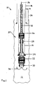
- Fig. 1 is a schematic side view of a wellbore with an expandable tubular member running into the wellbore supported at an end of a drill pipe by an expanding tool according to the invention.
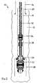
- Fig. 2 is a schematic side view of a wellbore with a portion of the expandable tubular member expanded by the expanding tool of Fig. 1 to create a launcher section.
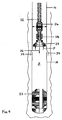
- Fig. 3 is a schematic side view of a wellbore with a bottom packer set in the launcher portion of the expandable tubular member and with the bottom packer released from the expander tool of Fig. 1.
- Fig. 4 is a schematic side view of a wellbore with a bottom packer set in the launcher portion of the expandable tubular member and with the bottom packer released from the expander tool of Fig. 1 and with the expandable tubular member expanded with the expander tool activated by hydraulic pressure created between the bottom packer and an expansion cone of the expander tool of Fig. 1.
- Fig. 5 is a schematic depiction of the engagement of a an anchor tool and the activation of a force multiplier in combination with the hydraulic pressure the cone to expand a bell at an overlapping portion between a previously expanded expandable member and the newly expanded expandable tubular member.
- Figs. 1-5 illustrate a bottom packer 22 used as part of an apparatus 10 and in connection with a method for forming a mono diameter wellbore casing 18 according several illustrative embodiments of the invention.
- the bottom packer 22 is used in connection with an expander tool 20 for expanding an expandable tubular member 14 in a wellbore 12.
- the invention is implemented using the methods and/or apparatus disclosed in one or more of the following: (1) U.S. patent application serial no. 09/454 , 139 , attorney docket no. 25791.03.02, filed on 12/3/1999, (2) U.S. patent application serial no. 09/510,913 , attorney docket no.
- provisional patent application serial no. 60/262,434 attorney docket no. 25791.51, filed on 1/17/2001, (24) U.S. provisional patent application serial no. 60/259,486 , attorney docket no. 25791.52, filed on 1/3/2001, (25) U.S. provisional patent application serial no. 60/303,740 , attorney docket no. 25791.61, filed on 7/6/2001, (26) U.S. provisional patent application serial no. 60/313,453 , attorney docket no. 25791.59, filed on 8/20/2001, (27) U.S. provisional patent application serial no. 60/317,985 , attorney docket no. 25791.67, filed on 9/6/2001, (28) U.S.
- provisional patent application serial no. 60/3318,386 attorney docket no. 25791.67.02, filed on 9/10/2001, (29)
- U.S. utility patent application serial no. 09/969,922 attorney docket no. 25791.69, filed on 10/3/2001,
- U.S. utility patent application serial no. 10/016,467 attorney docket no. 25791.70, filed on 12/10/2001,
- U.S. provisional patent application serial no. 60/343,674 attorney docket no. 25791.68, filed on 12/27/2001
- provisional patent application serial no. 60/412,177 attorney docket no. 25791.117, filed on 9/20/2002, (43)
- U.S. provisional patent application serial no. 60/412,653 attorney docket no. 25791.118, filed on 9/20/2002, (44)
- U.S. provisional patent application serial no. 60/412,544 attorney docket no. 25791.121, filed on 9/20/2002, (45)
- U.S. provisional patent application serial no. 60/412,187 attorney docket no. 25791.128, filed on 9/20/2002, (46)
- U.S. provisional patent application serial no. 60/412,187 attorney docket no.
- FIG. 1 an expansion apparatus 10 is shown run-in a wellbore 12.
- the expansion apparatus carries a tubular member 14 to be expanded, in the wellbore 12, below a previously expanded tubular member 16 that forms part of an existing casing 18.
- the expansion apparatus 10 includes an expander tool 20 and a bottom packer 22 (sometimes referred to as a bottom plug).
- the expander tool 20, an anchor 26 (sometimes referred to as a gripping tool), a force multiplier 28 (sometimes referred to as a hydraulic actuator), the bottom packer 22, and a float shoe valve 30 all carried on a drill pipe 32.
- the float shoe valve 30 may be incorporated into the bottom packer 22.
- the expansion cone 24 is a conventional expansion cone, or in the alternative is implemented using the methods and/or apparatus disclosed in one or more of the following: U.S. patent application serial no. 09/454,139 , attorney docket no. 25791.03.02, filed on 12/3/1999; U.S. patent application serial no. 09/510,913 , attorney docket no. 25791.7.02, filed on 2/23/2000; U.S. provisional patent application serial no. 60/380,147 , attorney docket no. 25791.104, filed on 5/6/2002; and/or U.S. provisional patent application serial no. 60/387,961 , attorney docket no. 25791.108, filed on 6/12/2002.
- the anchor 26 is a conventional anchor or conventional gripping tool, or in the alternative is implemented using the methods and/or apparatus disclosed in one or more of the following: U.S. provisional patent application serial no. 60/380,147 , attorney docket no. 25791.104, filed on 5/6/2002, and/or U.S. provisional patent application serial no. 60/387,961 , attorney docket no. 25791.108, filed on 6/12/2002.
- the force multiplier 28 or a conventional actuator such as a hydraulic actuator is implemented using the methods and/or apparatus disclosed in one or more of the following: U.S. provisional patent application serial no. 60/380,147 , attorney docket no. 25791.104, filed on 5/6/2002, and/or U.S. provisional patent application serial no. 60/387,961 , attorney docket no. 25791.108, filed on 6/12/2002.
- the wellbore 12 is drilled to a depth, below the previously expanded tubular member 16.
- the additional depth of the wellbore is estimated, based upon the length of the tubular member 14, to provide an overlap portion 34 between the previously expanded tubular member 16, or the existing casing 18, and the expandable tubular member 14 to be expanded.
- the expandable tubular member 14 is inserted, or run-in, to the a position that results in the overlap at overlapping portion 34.
- the expandable tubular member 14 will typically be cemented into the wellbore 12 by injecting fluid cement 36 through the drill pipe 32 and out through the float shoe valve 30 and into the wellbore below and around the bottom packer 22.
- the anchor 26 is activated, in a conventional manner or as disclosed in on or more of U.S. provisional patent application serial no. 60/380 , 147 , attorney docket no. 25791.104, filed on 5/6/2002, and/or U.S. provisional patent application serial no. 60/387,961 , attorney docket no.
- the force multiplier 28 is then stroked closed to move the expansion cone 24 firmly against the tubular member 14.
- the flow of fluidic material out of the float shoe 30 is stopped, for example, a valve in the float shoe may be closed by bumping the plug into the expansion cone assembly 24.
- Pressure builds in the force multiplier 28 to force the expansion cone 24 into the expandable tubular member 14 to pre-expand a lower section thereof and to thereby create a launcher section 38.
- the formed launcher section 38 is shown having an expanded inside diameter corresponding to the outside diameter of the expansion cone 24.
- Fig. 3 the displacement of the force multiplier 28 and expansion cone 24 releases the locked anchor 26.
- the force multiplier 28 is fully closed the pressure will rise. Fluid is pumped to increase pressure within the apparatus 10 and to thereby set the bottom packer 22 in the launcher section 38.
- a conventional packer setting tool 40 or a conventional packer setting mechanism is used to expand and sealing set the bottom packer 22 in the launcher section 38. For example, as shown in a partial cross section through the bottom packer 22 in Fig.
- such a setting tool 40 may be actuated conventionally by fluid pressure to progressively move together opposed conical wedge potions 42a and 42b of the bottom packer 22 and to progressively shear off shear pins 44a and 44b so that a flexible sealing ring 46 is compressed and expanded radially outward against the internal surface 48 of the launcher section 38.
- opposed external gripping elements 50a and 50b are forced by the conical wedge portions 42a and 42b, radially outward to engage the internal surface 48 of the launcher section 38 so that the bottom packer 22 is set in a sealed position.
- a conventional release mechanism 52 is activated to release the bottom packer 22 from the expansion cone 24.
- the release mechanism 52 may be activated by a shear out release device or by a rotation release device 52.
- the bottom packer 22 is thus set and effectively acts as a shoe by sealing off the expandable tubular member 14 from the wellbore 12. Additional fluid 36 is pumped through the drill pipe 32 to below the expansion cone 24, causing a hydraulic pressure P to increase between the expansion cone 24 and the sealed bottom packer 22.
- the anchor 26 is released and the cone 24 is forced upward through the expandable tubular member 14 by the force F on the expansion cone 24 created by the hydraulic pressure P.
- Fig. 4 shows that additional force may be required to move the expansion cone to expand the tubular member 14 at the overlap portion 30.
- the cone 24 is effectively expanding both of the two overlapping tubular members 14 and 16 at the same time.
- the anchor 26 can be engaged and the force multiplier 28 can be actuated to provide additional force for moving the expansion cone 24 through the overlap portion 34.
- a bell 54 is formed in the existing previously expanded tubular member 16 to accommodate the outside diameter of the simultaneously expanded new expandable tubular member 14.
- Fig. 5 shows one alternative operation of the expansion cone 24 run-in, after expansion of the expandable tubular member 14, to retrieve the bottom packer 22.
- a conventional oil tool retrieval mechanisms 56 may be used for this purpose.
- the bottom packer 22 is a drillable packer so that after expansion of the tubular member 14, the remainder of the expander tool 20, with the expansion cone 22, the anchor 26 and the force multiplier 28 attached, is tripped out of the wellbore leaving the expanded expandable tubular member 14, as part of the formed mono diameter casing 18, and the bottom packer 22 in place.
- the drillable bottom packer 22 is drilled out of the casing 18 and the next portion of the wellbore 12 is drilled to a next desired depth.
- Another apparatus 10 is provided with another expandable tubular member carried on the expander tool and it is run-in and positioned in the wellbore overlapping the previously expanded expandable tubular member and is expanded as described above. The process may be repeated until the total desired depth of the wellbore with a mono diameter casing is formed.
- a bottom plug for use in connection with an apparatus for forming a mono diameter wellbore casing the apparatus of the type using an expandable tubular member carried into the wellbore on a tubular support and expanded with an expansion cone connected to the tubular support has been disclosed.
- the bottom plug includes an expandable packer attached below the expansion cone, a packer setting mechanism coupled between the expansion cone and the expandable packer for expanding the expandable packer and sealingly setting it in an expanded portion of the expandable tubular member and a release mechanism coupled between the expansion cone and the expandable packer for releasing the expandable bottom packer from the expansion cone such that fluid pumped into the expandable tubular member between the expansion cone and the sealed and set expandable bottom packer will force the expansion cone into and through the expandable tubular member to expand the expandable tubular member.
- the bottom plug further includes a closable valve for selectively passing fluidic materials through the expandable packer into the wellbore.
- the expandable packer is a drillable packer.
- the expandable packer is a retrievable packer.
- an apparatus connectable to a drill pipe for forming a mono diameter wellbore casing that includes an expansion cone connected to the drill pipe, an expandable bottom packer coupled to and below the expansion cone, an expandable tubular member supported by the drill pipe above the expansion cone for insertion into the wellbore, an anchor device supported by the drill pipe within the expandable tubular member for releasably gripping the expandable tubular member, an actuator coupled between the anchor and the expansion cone for moving the cone partially into the expandable tubular member to form a first expanded portion of the expandable tubular member, a packer setting mechanism coupled between the expansion cone and the expandable bottom packer for expanding the expandable bottom packer and sealingly setting the expanded expandable bottom packer in the first expanded portion of the expandable tubular member, and a release mechanism coupled between the expansion cone and the expandable bottom packer for releasing the expandable bottom packer from the expansion cone so that fluid pumped into the expandable tubular member between the expansion cone and the expandable bottom packer forces the expansion cone through the expandable tubular member
- the apparatus for forming a mono diameter wellbore casing further includes a closable valve for selectively passing fluidic materials through the expandable bottom packer into the wellbore.
- the apparatus for forming a mono diameter wellbore casing the expandable bottom packer is a drillable packer.
- the apparatus for forming a mono diameter wellbore casing the expandable bottom packer is a retrievable packer.
- the bottom plug for use in connection with an apparatus for forming a mono diameter wellbore casing, the apparatus of the type using an expandable tubular member carried into the wellbore on a tubular support and expanded with an expansion device connected to the tubular support, the bottom plug includes an expandable packer attached below the expansion device, a packer setting mechanism coupled between the expansion device and the expandable packer for expanding the expandable packer and sealingly setting the expandable packer in an expanded portion of the expandable tubular member, and a release mechanism coupled between the expansion device and the expandable packer for releasing the expandable bottom packer from the expansion device so that fluid pumped into the expandable tubular member between the expansion device and the sealed and set expandable bottom packer will facilitate forcing the expansion device into and through the expandable tubular member to expand the expandable tubular member.
- the bottom plug is used with an adjustable diameter expansion cone.
- the bottom plug is used with a rotary expansion device.
- the bottom plug is used with an adjustable diameter expansion rotary expansion device.
- the bottom plug is used with a compliant expansion device.
- the bottom plug is used with an adjustable diameter expansion compliant expansion device.
- the bottom plug is used with a hydroforming expansion device.
- the bottom plug is used with an adjustable expansion diameter hydroforming device.
- a method for forming a mono diameter wellbore casing including connecting an expansion cone to a tubular support, coupling an expandable bottom packer to and below the expansion cone, supporting an expandable tubular member with the tubular support at position above the expansion cone, inserting the expandable tubular member into the wellbore, expanding a first portion of the expandable tubular member with the expansion cone, sealingly setting the expanded expandable bottom packer in the first expanded portion of the expandable tubular member, releasing the expandable bottom packer from the expansion cone, and pumping fluid into the expandable tubular member between the expansion cone and the set and expanded expandable bottom packer will force the expansion cone through the expandable tubular member to expand a second portion of the expandable tubular member.
- expanding the first portion of the expandable tubular member with the expansion cone further also includes releasably gripping the expandable tubular with an anchor device supported by the drill pipe within the expandable tubular member, coupling an actuator between the anchor and the expansion cone for moving the expansion cone with the actuator partially into the expandable tubular member to form a first expanded portion of the expandable tubular member.
- a method for forming a mono diameter wellbore casing including connecting an expansion device to a tubular support, coupling an expandable bottom packer to and below the expansion device, supporting an expandable tubular member with the tubular support at position above the expansion device, inserting the expandable tubular member into the wellbore, expanding a first portion of the expandable tubular member with the expansion device, sealingly setting the expanded expandable bottom packer in the first expanded portion of the expandable tubular member, and releasing the expandable bottom packer from the expansion device, and pumping fluid into the expandable tubular member between the expansion device and the set and expanded expandable bottom packer to facilitate forcing the expansion device through the expandable tubular member to expand a second portion of the expandable tubular member.
- expanding the first portion of the expandable tubular member with the expansion device includes gripping the expandable tubular member with an anchor device supported by the drill pipe, coupling an actuator between the anchor and the expansion cone, and moving the expansion device with the actuator partially into the expandable tubular member to form the first expanded portion of the expandable tubular member.
- expanding the first portion of the expandable tubular member with the expansion device further comprises expanding using an adjustable expansion device.
- Another embodiment of the method for forming a mono diameter wellbore casing is disclosed wherein expanding the first portion of the expandable tubular member with the expansion device further includes expanding using a rotary expansion device.
- Another embodiment of the method for forming a mono diameter wellbore casing is disclosed wherein expanding the first portion of the expandable tubular member with the expansion device further includes expanding using a compliant expansion device.
- expanding the first portion of the expandable tubular member with the expansion device further comprises expanding using a hydroforming expansion device.
- a conventional rotary expansion device may be used instead of, or in combination with, the expansion cone 24.
- a conventional compliant expansion device may be used instead of, or in combination with, the expansion cone 24.
- a conventional hydroforming expansion device may be used instead of, or in combination with, the expansion cone 24.
- one or more of the conventional commercially available expansion devices available from Weatherford International, Baker Hughes, Halliburton Energy Services, Schlumberger, and/or Enventure Global Technology may be used instead of, or in combination with, the expansion cone assembly 24.
Landscapes
- Geology (AREA)
- Life Sciences & Earth Sciences (AREA)
- Engineering & Computer Science (AREA)
- Mining & Mineral Resources (AREA)
- Environmental & Geological Engineering (AREA)
- Fluid Mechanics (AREA)
- Physics & Mathematics (AREA)
- General Life Sciences & Earth Sciences (AREA)
- Geochemistry & Mineralogy (AREA)
- Earth Drilling (AREA)
- Consolidation Of Soil By Introduction Of Solidifying Substances Into Soil (AREA)
- Pens And Brushes (AREA)
- Structures Of Non-Positive Displacement Pumps (AREA)
- Absorbent Articles And Supports Therefor (AREA)
- Soil Working Implements (AREA)
Claims (14)
- Procédé de formation d'un tubage de puits de forage à diamètre unique, comprenant les étapes consistant àmonter un dispositif d'expansion (24) sur un support tubulaire (32) ;coupler un packer de fond extensible (22) à et sous le dispositif d'expansion (24) ;supporter un élément tubulaire extensible (14) avec le support tubulaire (32) ;insérer l'élément tubulaire extensible (14) dans un puits de forage (12) ;développer ensuite une première partie (38) de l'élément tubulaire extensible (14) avec le dispositif d'expansion (24) ;régler de manière étanche le packer de fond extensible étendu (22) dans la première partie développée (38) de l'élément tubulaire extensible (14) ;libérer le packer de fond extensible du dispositif d'expansion ;puis pomper du fluide (36) dans l'élément tubulaire extensible (14) entre le dispositif d'expansion (24) et le packer de fond extensible étendu et réglé pour forcer le dispositif d'expansion (24) à travers l'élément tubulaire extensible (14) à développer une deuxième partie de l'élément tubulaire extensible (14).
- Procédé selon la revendication 1, dans lequel le développement de la première partie (38) de l'élément tubulaire extensible (14) avec le dispositif d'expansion (24) comprend les opérations consistant à :saisir l'élément tubulaire extensible (14) avec un dispositif d'ancrage (26) supporté par le support tubulaire (32) ;coupler un actionneur (28) entre le dispositif d'ancrage (26) et le dispositif d'expansion (24) ; etdéplacer le dispositif d'expansion (24) avec l'actionneur (28) partiellement dans l'élément tubulaire extensible (14) pour former la première partie (38) de l'élément tubulaire extensible (14).
- Procédé selon la revendication 1, dans lequel le développement de la première partie (38) de l'élément tubulaire extensible (14) avec le dispositif d'expansion (24) comprend le fait de développer à l'aide d'un dispositif d'expansion réglable (24).
- Procédé selon la revendication 1, dans lequel le développement de la première partie (38) de l'élément tubulaire extensible (14) avec le dispositif d'expansion (24) comprend le fait de développer à l'aide d'un dispositif d'expansion rotatif (24).
- Procédé selon la revendication 1, dans lequel le développement de la première partie (38) de l'élément tubulaire extensible (14) avec le dispositif d'expansion (24) comprend le fait de développer à l'aide d'un dispositif d'expansion souple (24).
- Procédé selon la revendication 1, dans lequel le développement de la première partie (38) de l'élément tubulaire extensible (14) avec le dispositif d'expansion (24) comprend le fait de développer à l'aide d'un dispositif d'expansion à hydroformage (24).
- Procédé selon la revendication 1, dans lequel le développement de la première partie (38) de l'élément tubulaire extensible (14) avec le dispositif d'expansion (24) comprend le fait de déplacer le dispositif d'expansion (24) en utilisant un actionneur hydraulique (28).
- Procédé selon la revendication 7, dans lequel l'actionneur hydraulique (28) comprend un multiplicateur d'effort (28).
- Procédé selon la revendication 1, dans lequel l'obturation de la première partie développée (38) de l'élément tubulaire extensible (14) comprend le fait d'obturer la première partie développée (38) de l'élément tubulaire extensible (14) en employant un packer (22).
- Procédé selon la revendication 9, dans lequel le packer (22) comprend un packer forable (22).
- Procédé selon la revendication 9, dans lequel le packer (22) comprend un packer récupérable (22).
- Procédé selon la revendication 1, dans lequel l'insertion de l'élément tubulaire extensible (14) dans le puits de forage (12) comprend le fait d'insérer l'élément tubulaire extensible (14) dans le puits de forage (12) jusqu'à une position dans laquelle il chevauche un tubage existant (18) positionné à l'intérieur du puits de forage (12).
- Procédé selon la revendication 12, dans lequel le développement de la deuxième partie de l'élément tubulaire extensible (14) comprend le fait de développer une partie (30) du tubage existant (18) qui chevauche l'élément tubulaire extensible (14).
- Procédé selon la revendication 1, dans lequel le support d'un élément tubulaire extensible (14) au moyen du support tubulaire (32) comprend le fait de supporter l'élément tubulaire extensible (14) avec le support tubulaire (32) en une position située au-dessus du dispositif d'expansion (24).
Applications Claiming Priority (3)
| Application Number | Priority Date | Filing Date | Title |
|---|---|---|---|
| US41248802P | 2002-09-20 | 2002-09-20 | |
| US412488P | 2002-09-20 | ||
| PCT/US2003/029460 WO2004027200A2 (fr) | 2002-09-20 | 2003-09-22 | Bouchon inferieur pour la formation d'un tubage de puits de forage de diametre unique |
Publications (3)
| Publication Number | Publication Date |
|---|---|
| EP1549823A2 EP1549823A2 (fr) | 2005-07-06 |
| EP1549823A4 EP1549823A4 (fr) | 2006-03-22 |
| EP1549823B1 true EP1549823B1 (fr) | 2007-07-25 |
Family
ID=32030886
Family Applications (1)
| Application Number | Title | Priority Date | Filing Date |
|---|---|---|---|
| EP03752486A Expired - Lifetime EP1549823B1 (fr) | 2002-09-20 | 2003-09-22 | Bouchon inferieur pour la formation d'un tubage de puits de forage de diametre unique |
Country Status (10)
| Country | Link |
|---|---|
| US (1) | US7513313B2 (fr) |
| EP (1) | EP1549823B1 (fr) |
| AT (1) | ATE368169T1 (fr) |
| AU (1) | AU2003270774A1 (fr) |
| BR (1) | BR0314627A (fr) |
| CA (1) | CA2499007C (fr) |
| DE (1) | DE60315172T2 (fr) |
| MX (1) | MXPA05003116A (fr) |
| NO (1) | NO336661B1 (fr) |
| WO (1) | WO2004027200A2 (fr) |
Families Citing this family (44)
| Publication number | Priority date | Publication date | Assignee | Title |
|---|---|---|---|---|
| US7357188B1 (en) | 1998-12-07 | 2008-04-15 | Shell Oil Company | Mono-diameter wellbore casing |
| CA2407983C (fr) * | 1998-11-16 | 2010-01-12 | Robert Lance Cook | Dilatation radiale d'elements tubulaires |
| US7363984B2 (en) * | 1998-12-07 | 2008-04-29 | Enventure Global Technology, Llc | System for radially expanding a tubular member |
| AU770359B2 (en) * | 1999-02-26 | 2004-02-19 | Shell Internationale Research Maatschappij B.V. | Liner hanger |
| US20050123639A1 (en) * | 1999-10-12 | 2005-06-09 | Enventure Global Technology L.L.C. | Lubricant coating for expandable tubular members |
| US7100685B2 (en) * | 2000-10-02 | 2006-09-05 | Enventure Global Technology | Mono-diameter wellbore casing |
| US7775290B2 (en) | 2003-04-17 | 2010-08-17 | Enventure Global Technology, Llc | Apparatus for radially expanding and plastically deforming a tubular member |
| AU2002319813A1 (en) * | 2001-09-07 | 2003-03-24 | Enventure Global Technology | Adjustable expansion cone assembly |
| US7793721B2 (en) | 2003-03-11 | 2010-09-14 | Eventure Global Technology, Llc | Apparatus for radially expanding and plastically deforming a tubular member |
| NL1019368C2 (nl) | 2001-11-14 | 2003-05-20 | Nutricia Nv | Preparaat voor het verbeteren van receptorwerking. |
| CA2482743C (fr) | 2002-04-12 | 2011-05-24 | Enventure Global Technology | Manchon de protection a elements de raccordement filetes pour suspension de la colonne perdue |
| CA2482278A1 (fr) | 2002-04-15 | 2003-10-30 | Enventure Global Technology | Manchon protecteur destine aux connexions filetees d'un dispositif de suspension pour colonne de tubage perdue expansible |
| CA2493086A1 (fr) * | 2002-07-19 | 2004-01-29 | Enventure Global Technology | Manchon de protection pour raccords filetes de suspension de colonne perdue expansible |
| AU2003261451A1 (en) * | 2002-08-30 | 2004-03-19 | Enventure Global Technology | Method of manufacturing an insulated pipeline |
| MXPA05003115A (es) | 2002-09-20 | 2005-08-03 | Eventure Global Technology | Evaluacion de formabilidad de un tubo para miembros tubulares expandibles. |
| US7886831B2 (en) | 2003-01-22 | 2011-02-15 | Enventure Global Technology, L.L.C. | Apparatus for radially expanding and plastically deforming a tubular member |
| GB2415215B (en) * | 2003-01-27 | 2007-05-23 | Enventure Global Technology | Lubrication system for radially expanding tubular members |
| GB2433757B (en) * | 2003-03-11 | 2007-10-31 | Enventure Global Technology | Apparatus for radially expanding and plastically deforming a tubular member |
| GB0412131D0 (en) | 2004-05-29 | 2004-06-30 | Weatherford Lamb | Coupling and seating tubulars in a bore |
| US20050166387A1 (en) * | 2003-06-13 | 2005-08-04 | Cook Robert L. | Method and apparatus for forming a mono-diameter wellbore casing |
| US7712522B2 (en) | 2003-09-05 | 2010-05-11 | Enventure Global Technology, Llc | Expansion cone and system |
| WO2005024171A2 (fr) * | 2003-09-05 | 2005-03-17 | Enventure Global Technology, Llc | Element tubulaire expansible |
| CA2577083A1 (fr) | 2004-08-13 | 2006-02-23 | Mark Shuster | Dispositif d'expansion d'elements tubulaires |
| US8069916B2 (en) * | 2007-01-03 | 2011-12-06 | Weatherford/Lamb, Inc. | System and methods for tubular expansion |
| US7779910B2 (en) * | 2008-02-07 | 2010-08-24 | Halliburton Energy Services, Inc. | Expansion cone for expandable liner hanger |
| CA2749593C (fr) * | 2008-04-23 | 2012-03-20 | Weatherford/Lamb, Inc. | Agencement a alesage unique avec doubles dispositifs d'expansion |
| US7854266B2 (en) * | 2008-09-26 | 2010-12-21 | Halliburton Energy Services, Inc. | Smooth bore latch for tie back receptacle extension |
| BRPI0921309A2 (pt) * | 2008-11-18 | 2017-05-30 | Shell Int Research | método para expandir um tubular em um furo de sondagem |
| US20100132958A1 (en) * | 2008-12-02 | 2010-06-03 | Odenthal Robert S | Expandable tubular installation systems, methods, and apparatus |
| US8100186B2 (en) * | 2009-07-15 | 2012-01-24 | Enventure Global Technology, L.L.C. | Expansion system for expandable tubulars and method of expanding thereof |
| US8261842B2 (en) | 2009-12-08 | 2012-09-11 | Halliburton Energy Services, Inc. | Expandable wellbore liner system |
| US8230926B2 (en) | 2010-03-11 | 2012-07-31 | Halliburton Energy Services Inc. | Multiple stage cementing tool with expandable sealing element |
| US8826990B2 (en) | 2010-07-15 | 2014-09-09 | Deep Sea Innovations, Llc | Apparatuses and methods for closing and reopening a pipe |
| EP2593638B1 (fr) | 2010-07-15 | 2019-01-09 | Deep Sea Innovations, LLC | Appareils et procédés d'obturation et de réouverture d'une conduite |
| GB201108724D0 (en) * | 2011-05-24 | 2011-07-06 | Coretrax Technology Ltd | Support device for use in a wellbore and a method for displaying a barrier in a wellbore |
| US8820419B2 (en) * | 2012-05-23 | 2014-09-02 | Baker Hughes Incorporated | Washover tieback method |
| GB2540511B (en) | 2014-06-25 | 2020-11-25 | Shell Int Research | Assembly and method for expanding a tubular element |
| GB2543214B (en) | 2014-08-13 | 2017-10-04 | Shell Int Research | Assembly and method for creating an expanded tubular element in a borehole |
| US9874062B2 (en) | 2014-10-15 | 2018-01-23 | Halliburton Energy Services, Inc. | Expandable latch coupling assembly |
| WO2016091967A1 (fr) * | 2014-12-12 | 2016-06-16 | Shell Internationale Research Maatschappij B.V. | Procédé et système d'installation d'un élément tubulaire dans un puits de forage |
| BR112017010455A2 (pt) | 2014-12-12 | 2017-12-26 | Shell Int Research | sistema e método para expandir radialmente um elemento tubular |
| WO2017001386A1 (fr) * | 2015-07-01 | 2017-01-05 | Shell Internationale Research Maatschappij B.V. | Procédé et système pour améliorer les performances d'un ensemble de dilatation tubulaire de puits |
| EP3255240A1 (fr) * | 2016-06-10 | 2017-12-13 | Welltec A/S | Système de chevauchement de fond de trou |
| US11352858B2 (en) | 2017-02-09 | 2022-06-07 | Enventure Global Technology Inc. | Liner hanger for use with an expansion tool having an adjustable cone |
Family Cites Families (187)
| Publication number | Priority date | Publication date | Assignee | Title |
|---|---|---|---|---|
| US331940A (en) | 1885-12-08 | Half to ralph bagaley | ||
| US332184A (en) | 1885-12-08 | William a | ||
| US2735485A (en) | 1956-02-21 | metcalf | ||
| US46818A (en) | 1865-03-14 | Improvement in tubes for caves in oil or other wells | ||
| US519805A (en) | 1894-05-15 | Charles s | ||
| US341237A (en) | 1886-05-04 | Bicycle | ||
| US2734580A (en) | 1956-02-14 | layne | ||
| US802880A (en) | 1905-03-15 | 1905-10-24 | Thomas W Phillips Jr | Oil-well packer. |
| US806156A (en) | 1905-03-28 | 1905-12-05 | Dale Marshall | Lock for nuts and bolts and the like. |
| US984449A (en) | 1909-08-10 | 1911-02-14 | John S Stewart | Casing mechanism. |
| US958517A (en) | 1909-09-01 | 1910-05-17 | John Charles Mettler | Well-casing-repairing tool. |
| US1166040A (en) | 1915-03-28 | 1915-12-28 | William Burlingham | Apparatus for lining tubes. |
| US1233888A (en) | 1916-09-01 | 1917-07-17 | Frank W A Finley | Art of well-producing or earth-boring. |
| US1358818A (en) | 1920-04-07 | 1920-11-16 | Bering Robert Ellis | Casing-cutter |
| US1494128A (en) | 1921-06-11 | 1924-05-13 | Power Specialty Co | Method and apparatus for expanding tubes |
| US1597212A (en) | 1924-10-13 | 1926-08-24 | Arthur F Spengler | Casing roller |
| US1590357A (en) | 1925-01-14 | 1926-06-29 | John F Penrose | Pipe joint |
| US1739932A (en) | 1925-05-18 | 1929-12-17 | Ventresca Ercole | Inside casing cutter |
| US1589781A (en) | 1925-11-09 | 1926-06-22 | Joseph M Anderson | Rotary tool joint |
| US1613461A (en) | 1926-06-01 | 1927-01-04 | Edwin A Johnson | Connection between well-pipe sections of different materials |
| US1756531A (en) | 1928-05-12 | 1930-04-29 | Fyrac Mfg Co | Post light |
| US1880218A (en) | 1930-10-01 | 1932-10-04 | Richard P Simmons | Method of lining oil wells and means therefor |
| US1952652A (en) | 1932-11-05 | 1934-03-27 | Robert D Brannon | Well pipe cutter |
| US1981525A (en) | 1933-12-05 | 1934-11-20 | Bailey E Price | Method of and apparatus for drilling oil wells |
| US2046870A (en) | 1934-05-08 | 1936-07-07 | Clasen Anthony | Method of repairing wells having corroded sand points |
| US2122757A (en) | 1935-07-05 | 1938-07-05 | Hughes Tool Co | Drill stem coupling |
| US2145168A (en) | 1935-10-21 | 1939-01-24 | Flagg Ray | Method of making pipe joint connections |
| US2134311A (en) | 1936-05-22 | 1938-10-25 | Regan Forge & Engineering Comp | Method and apparatus for suspending and sealing well casings |
| US2110913A (en) | 1936-08-22 | 1938-03-15 | Hall And Lowrey Inc | Pipe cutting apparatus |
| US2087185A (en) | 1936-08-24 | 1937-07-13 | Stephen V Dillon | Well string |
| US2187275A (en) | 1937-01-12 | 1940-01-16 | Amos N Mclennan | Means for locating and cementing off leaks in well casings |
| US2226804A (en) | 1937-02-05 | 1940-12-31 | Johns Manville | Liner for wells |
| US2160263A (en) | 1937-03-18 | 1939-05-30 | Hughes Tool Co | Pipe joint and method of making same |
| US2211173A (en) | 1938-06-06 | 1940-08-13 | Ernest J Shaffer | Pipe coupling |
| US2204586A (en) | 1938-06-15 | 1940-06-18 | Byron Jackson Co | Safety tool joint |
| US2246038A (en) | 1939-02-23 | 1941-06-17 | Jones & Laughlin Steel Corp | Integral joint drill pipe |
| US2214226A (en) | 1939-03-29 | 1940-09-10 | English Aaron | Method and apparatus useful in drilling and producing wells |
| US2301495A (en) | 1939-04-08 | 1942-11-10 | Abegg & Reinhold Co | Method and means of renewing the shoulders of tool joints |
| US2273017A (en) | 1939-06-30 | 1942-02-17 | Boynton Alexander | Right and left drill pipe |
| US2371840A (en) | 1940-12-03 | 1945-03-20 | Herbert C Otis | Well device |
| US2305282A (en) | 1941-03-22 | 1942-12-15 | Guiberson Corp | Swab cup construction and method of making same |
| US2383214A (en) | 1943-05-18 | 1945-08-21 | Bessie Pugsley | Well casing expander |
| US2447629A (en) | 1944-05-23 | 1948-08-24 | Richfield Oil Corp | Apparatus for forming a section of casing below casing already in position in a well hole |
| US2407552A (en) | 1944-07-01 | 1946-09-10 | Anthony F Hoesel | Pipe thread gasket |
| US2481637A (en) | 1945-02-23 | 1949-09-13 | A 1 Bit & Tool Company | Combined milling tool and pipe puller |
| US2500276A (en) | 1945-12-22 | 1950-03-14 | Walter L Church | Safety joint |
| US2546295A (en) | 1946-02-08 | 1951-03-27 | Reed Roller Bit Co | Tool joint wear collar |
| US2609258A (en) | 1947-02-06 | 1952-09-02 | Guiberson Corp | Well fluid holding device |
| US2583316A (en) | 1947-12-09 | 1952-01-22 | Clyde E Bannister | Method and apparatus for setting a casing structure in a well hole or the like |
| US2664952A (en) | 1948-03-15 | 1954-01-05 | Guiberson Corp | Casing packer cup |
| US2647847A (en) | 1950-02-28 | 1953-08-04 | Fluid Packed Pump Company | Method for interfitting machined parts |
| US2627891A (en) | 1950-11-28 | 1953-02-10 | Paul B Clark | Well pipe expander |
| US2691418A (en) | 1951-06-23 | 1954-10-12 | John A Connolly | Combination packing cup and slips |
| US2723721A (en) | 1952-07-14 | 1955-11-15 | Seanay Inc | Packer construction |
| US3018547A (en) | 1952-07-30 | 1962-01-30 | Babcock & Wilcox Co | Method of making a pressure-tight mechanical joint for operation at elevated temperatures |
| US2695449A (en) | 1952-10-28 | 1954-11-30 | Willie L Chauvin | Subsurface pipe cutter for drill pipes |
| US2877822A (en) | 1953-08-24 | 1959-03-17 | Phillips Petroleum Co | Hydraulically operable reciprocating motor driven swage for restoring collapsed pipe |
| US2796134A (en) | 1954-07-19 | 1957-06-18 | Exxon Research Engineering Co | Apparatus for preventing lost circulation in well drilling operations |
| US2812025A (en) | 1955-01-24 | 1957-11-05 | James U Teague | Expansible liner |
| US2919741A (en) | 1955-09-22 | 1960-01-05 | Blaw Knox Co | Cold pipe expanding apparatus |
| US2907589A (en) | 1956-11-05 | 1959-10-06 | Hydril Co | Sealed joint for tubing |
| US2929741A (en) | 1957-11-04 | 1960-03-22 | Morris A Steinberg | Method for coating graphite with metallic carbides |
| US3067819A (en) | 1958-06-02 | 1962-12-11 | George L Gore | Casing interliner |
| US3068563A (en) | 1958-11-05 | 1962-12-18 | Westinghouse Electric Corp | Metal joining method |
| US3067801A (en) | 1958-11-13 | 1962-12-11 | Fmc Corp | Method and apparatus for installing a well liner |
| US3015362A (en) | 1958-12-15 | 1962-01-02 | Johnston Testers Inc | Well apparatus |
| US3015500A (en) | 1959-01-08 | 1962-01-02 | Dresser Ind | Drill string joint |
| US3039530A (en) | 1959-08-26 | 1962-06-19 | Elmo L Condra | Combination scraper and tube reforming device and method of using same |
| US3104703A (en) | 1960-08-31 | 1963-09-24 | Jersey Prod Res Co | Borehole lining or casing |
| US3209546A (en) | 1960-09-21 | 1965-10-05 | Lawton Lawrence | Method and apparatus for forming concrete piles |
| US3111991A (en) | 1961-05-12 | 1963-11-26 | Pan American Petroleum Corp | Apparatus for repairing well casing |
| US3175618A (en) | 1961-11-06 | 1965-03-30 | Pan American Petroleum Corp | Apparatus for placing a liner in a vessel |
| US3191680A (en) | 1962-03-14 | 1965-06-29 | Pan American Petroleum Corp | Method of setting metallic liners in wells |
| US3167122A (en) | 1962-05-04 | 1965-01-26 | Pan American Petroleum Corp | Method and apparatus for repairing casing |
| US3203451A (en) | 1962-08-09 | 1965-08-31 | Pan American Petroleum Corp | Corrugated tube for lining wells |
| US3179168A (en) | 1962-08-09 | 1965-04-20 | Pan American Petroleum Corp | Metallic casing liner |
| US3203483A (en) | 1962-08-09 | 1965-08-31 | Pan American Petroleum Corp | Apparatus for forming metallic casing liner |
| US3188816A (en) | 1962-09-17 | 1965-06-15 | Koch & Sons Inc H | Pile forming method |
| US3233315A (en) | 1962-12-04 | 1966-02-08 | Plastic Materials Inc | Pipe aligning and joining apparatus |
| US3245471A (en) | 1963-04-15 | 1966-04-12 | Pan American Petroleum Corp | Setting casing in wells |
| US3191677A (en) | 1963-04-29 | 1965-06-29 | Myron M Kinley | Method and apparatus for setting liners in tubing |
| US3343252A (en) | 1964-03-03 | 1967-09-26 | Reynolds Metals Co | Conduit system and method for making the same or the like |
| US3270817A (en) | 1964-03-26 | 1966-09-06 | Gulf Research Development Co | Method and apparatus for installing a permeable well liner |
| US3354955A (en) | 1964-04-24 | 1967-11-28 | William B Berry | Method and apparatus for closing and sealing openings in a well casing |
| US3364993A (en) | 1964-06-26 | 1968-01-23 | Wilson Supply Company | Method of well casing repair |
| US3326293A (en) | 1964-06-26 | 1967-06-20 | Wilson Supply Company | Well casing repair |
| US3297092A (en) | 1964-07-15 | 1967-01-10 | Pan American Petroleum Corp | Casing patch |
| US3210102A (en) | 1964-07-22 | 1965-10-05 | Joslin Alvin Earl | Pipe coupling having a deformed inner lock |
| US3353599A (en) | 1964-08-04 | 1967-11-21 | Gulf Oil Corp | Method and apparatus for stabilizing formations |
| US3358769A (en) | 1965-05-28 | 1967-12-19 | William B Berry | Transporter for well casing interliner or boot |
| US3371717A (en) | 1965-09-21 | 1968-03-05 | Baker Oil Tools Inc | Multiple zone well production apparatus |
| US3358760A (en) | 1965-10-14 | 1967-12-19 | Schlumberger Technology Corp | Method and apparatus for lining wells |
| US3389752A (en) | 1965-10-23 | 1968-06-25 | Schlumberger Technology Corp | Zone protection |
| FR1489013A (fr) * | 1965-11-05 | 1967-07-21 | Vallourec | Joint d'assemblage pour tubes métalliques |
| US3427707A (en) | 1965-12-16 | 1969-02-18 | Connecticut Research & Mfg Cor | Method of joining a pipe and fitting |
| US3422902A (en) | 1966-02-21 | 1969-01-21 | Herschede Hall Clock Co The | Well pack-off unit |
| US3397745A (en) | 1966-03-08 | 1968-08-20 | Carl Owens | Vacuum-insulated steam-injection system for oil wells |
| US3412565A (en) | 1966-10-03 | 1968-11-26 | Continental Oil Co | Method of strengthening foundation piling |
| US3424244A (en) | 1967-09-14 | 1969-01-28 | Kinley Co J C | Collapsible support and assembly for casing or tubing liner or patch |
| US3463228A (en) | 1967-12-29 | 1969-08-26 | Halliburton Co | Torque resistant coupling for well tool |
| US3489220A (en) * | 1968-08-02 | 1970-01-13 | J C Kinley | Method and apparatus for repairing pipe in wells |
| US3631926A (en) * | 1969-12-31 | 1972-01-04 | Schlumberger Technology Corp | Well packer |
| US3711123A (en) * | 1971-01-15 | 1973-01-16 | Hydro Tech Services Inc | Apparatus for pressure testing annular seals in an oversliding connector |
| US3709306A (en) * | 1971-02-16 | 1973-01-09 | Baker Oil Tools Inc | Threaded connector for impact devices |
| US3785193A (en) * | 1971-04-10 | 1974-01-15 | Kinley J | Liner expanding apparatus |
| US3712376A (en) * | 1971-07-26 | 1973-01-23 | Gearhart Owen Industries | Conduit liner for wellbore and method and apparatus for setting same |
| US3781966A (en) * | 1972-12-04 | 1974-01-01 | Whittaker Corp | Method of explosively expanding sleeves in eroded tubes |
| US3866954A (en) * | 1973-06-18 | 1975-02-18 | Bowen Tools Inc | Joint locking device |
| FR2234448B1 (fr) * | 1973-06-25 | 1977-12-23 | Petroles Cie Francaise | |
| BR7600832A (pt) * | 1975-05-01 | 1976-11-09 | Caterpillar Tractor Co | Montagem de tubo junta preparada para um ajustador e metodo para juntar mecanicamente um ajustador a extremidade de um comprimento de tubo metalico |
| US4069573A (en) * | 1976-03-26 | 1978-01-24 | Combustion Engineering, Inc. | Method of securing a sleeve within a tube |
| US4190108A (en) * | 1978-07-19 | 1980-02-26 | Webber Jack C | Swab |
| SE427764B (sv) * | 1979-03-09 | 1983-05-02 | Atlas Copco Ab | Bergbultningsforfarande jemte rorformig bergbult |
| US4635333A (en) * | 1980-06-05 | 1987-01-13 | The Babcock & Wilcox Company | Tube expanding method |
| US4423889A (en) * | 1980-07-29 | 1984-01-03 | Dresser Industries, Inc. | Well-tubing expansion joint |
| NO159201C (no) * | 1980-09-08 | 1988-12-07 | Atlas Copco Ab | Fremgangsmaate ved bolting i fjell og kombinert ekspansjonsbolt og installasjonsanordning for samme. |
| US4368571A (en) * | 1980-09-09 | 1983-01-18 | Westinghouse Electric Corp. | Sleeving method |
| US4366971A (en) * | 1980-09-17 | 1983-01-04 | Allegheny Ludlum Steel Corporation | Corrosion resistant tube assembly |
| US4424865A (en) * | 1981-09-08 | 1984-01-10 | Sperry Corporation | Thermally energized packer cup |
| US4429741A (en) * | 1981-10-13 | 1984-02-07 | Christensen, Inc. | Self powered downhole tool anchor |
| JPS58107292A (ja) * | 1981-12-21 | 1983-06-25 | Kawasaki Heavy Ind Ltd | 管の溶接継手部処理方法及び装置 |
| US4501327A (en) * | 1982-07-19 | 1985-02-26 | Philip Retz | Split casing block-off for gas or water in oil drilling |
| US4495073A (en) * | 1983-10-21 | 1985-01-22 | Baker Oil Tools, Inc. | Retrievable screen device for drill pipe and the like |
| US4637436A (en) * | 1983-11-15 | 1987-01-20 | Raychem Corporation | Annular tube-like driver |
| US4796668A (en) * | 1984-01-09 | 1989-01-10 | Vallourec | Device for protecting threadings and butt-type joint bearing surfaces of metallic tubes |
| JPS63167108A (ja) * | 1986-12-26 | 1988-07-11 | 三菱電機株式会社 | 固着装置 |
| JPS63293384A (ja) * | 1987-05-27 | 1988-11-30 | 住友金属工業株式会社 | ねじ継手付frp管 |
| US4892337A (en) * | 1988-06-16 | 1990-01-09 | Exxon Production Research Company | Fatigue-resistant threaded connector |
| SE466690B (sv) * | 1988-09-06 | 1992-03-23 | Exploweld Ab | Foerfarande foer explosionssvetsning av roer |
| WO1990005833A1 (fr) * | 1988-11-22 | 1990-05-31 | Tatarsky Gosudarstvenny Nauchno-Issledovatelsky I Proektny Institut Neftyanoi Promyshlennosti | Dispositif pour obturer une zone de complications dans un puits |
| DE8902572U1 (fr) * | 1989-03-03 | 1990-07-05 | Siemens Ag, 1000 Berlin Und 8000 Muenchen, De | |
| US4995464A (en) * | 1989-08-25 | 1991-02-26 | Dril-Quip, Inc. | Well apparatus and method |
| MY106026A (en) * | 1989-08-31 | 1995-02-28 | Union Oil Company Of California | Well casing flotation device and method |
| BR9102789A (pt) * | 1991-07-02 | 1993-02-09 | Petroleo Brasileiro Sa | Processo para aumentar a recuperacao de petroleo em reservatorios |
| US5282652A (en) * | 1991-10-22 | 1994-02-01 | Werner Pipe Service, Inc. | Lined pipe joint and seal |
| US5297629A (en) * | 1992-01-23 | 1994-03-29 | Halliburton Company | Drill stem testing with tubing conveyed perforation |
| US5286393A (en) * | 1992-04-15 | 1994-02-15 | Jet-Lube, Inc. | Coating and bonding composition |
| US5390735A (en) * | 1992-08-24 | 1995-02-21 | Halliburton Company | Full bore lock system |
| US5275242A (en) * | 1992-08-31 | 1994-01-04 | Union Oil Company Of California | Repositioned running method for well tubulars |
| US5361843A (en) * | 1992-09-24 | 1994-11-08 | Halliburton Company | Dedicated perforatable nipple with integral isolation sleeve |
| US5492173A (en) * | 1993-03-10 | 1996-02-20 | Halliburton Company | Plug or lock for use in oil field tubular members and an operating system therefor |
| FR2703102B1 (fr) * | 1993-03-25 | 1999-04-23 | Drillflex | Procédé de cimentation d'un tubage déformable à l'intérieur d'un puits de forage ou d'une canalisation. |
| US5388648A (en) * | 1993-10-08 | 1995-02-14 | Baker Hughes Incorporated | Method and apparatus for sealing the juncture between a vertical well and one or more horizontal wells using deformable sealing means |
| FR2717855B1 (fr) * | 1994-03-23 | 1996-06-28 | Drifflex | Procédé pour rendre étanche la liaison entre un chemisage intérieur d'une part, et un puits de forage, un tubage ou une canalisation extérieure d'autre part. |
| AT404386B (de) * | 1994-05-25 | 1998-11-25 | Johann Dipl Ing Springer | Doppelwandiger thermisch isolierter tubingstrang |
| US6027145A (en) * | 1994-10-04 | 2000-02-22 | Nippon Steel Corporation | Joint for steel pipe having high galling resistance and surface treatment method thereof |
| ZA96241B (en) * | 1995-01-16 | 1996-08-14 | Shell Int Research | Method of creating a casing in a borehole |
| UA67719C2 (en) * | 1995-11-08 | 2004-07-15 | Shell Int Research | Deformable well filter and method for its installation |
| US5697449A (en) * | 1995-11-22 | 1997-12-16 | Baker Hughes Incorporated | Apparatus and method for temporary subsurface well sealing and equipment anchoring |
| GB9524109D0 (en) * | 1995-11-24 | 1996-01-24 | Petroline Wireline Services | Downhole apparatus |
| US6564867B2 (en) * | 1996-03-13 | 2003-05-20 | Schlumberger Technology Corporation | Method and apparatus for cementing branch wells from a parent well |
| WO1998009049A1 (fr) * | 1996-08-30 | 1998-03-05 | Camco International, Inc. | Procede et appareil permettant d'etancheifier un raccord entre un trou de forage principal et un trou de forage lateral |
| US5857524A (en) * | 1997-02-27 | 1999-01-12 | Harris; Monty E. | Liner hanging, sealing and cementing tool |
| EP0863191A3 (fr) * | 1997-03-05 | 1999-01-27 | Nippon Paint Co., Ltd. | Film de peinture résistante à la contamination par la pluie, composition de revêtement, procédé de formation d'un film et produits revêtus |
| US6012874A (en) * | 1997-03-14 | 2000-01-11 | Dbm Contractors, Inc. | Micropile casing and method |
| US6672759B2 (en) * | 1997-07-11 | 2004-01-06 | International Business Machines Corporation | Method for accounting for clamp expansion in a coefficient of thermal expansion measurement |
| US6029748A (en) * | 1997-10-03 | 2000-02-29 | Baker Hughes Incorporated | Method and apparatus for top to bottom expansion of tubulars |
| US6021850A (en) * | 1997-10-03 | 2000-02-08 | Baker Hughes Incorporated | Downhole pipe expansion apparatus and method |
| US6260617B1 (en) * | 1997-11-21 | 2001-07-17 | Superior Energy Services, L.L.C. | Skate apparatus for injecting tubing down pipelines |
| US6017168A (en) * | 1997-12-22 | 2000-01-25 | Abb Vetco Gray Inc. | Fluid assist bearing for telescopic joint of a RISER system |
| US6012521A (en) * | 1998-02-09 | 2000-01-11 | Etrema Products, Inc. | Downhole pressure wave generator and method for use thereof |
| US6167970B1 (en) * | 1998-04-30 | 2001-01-02 | B J Services Company | Isolation tool release mechanism |
| US6135208A (en) * | 1998-05-28 | 2000-10-24 | Halliburton Energy Services, Inc. | Expandable wellbore junction |
| US6182775B1 (en) * | 1998-06-10 | 2001-02-06 | Baker Hughes Incorporated | Downhole jar apparatus for use in oil and gas wells |
| US6009611A (en) * | 1998-09-24 | 2000-01-04 | Oil & Gas Rental Services, Inc. | Method for detecting wear at connections between pin and box joints |
| US6823937B1 (en) * | 1998-12-07 | 2004-11-30 | Shell Oil Company | Wellhead |
| GB2344606B (en) * | 1998-12-07 | 2003-08-13 | Shell Int Research | Forming a wellbore casing by expansion of a tubular member |
| FR2791293B1 (fr) * | 1999-03-23 | 2001-05-18 | Sonats Soc Des Nouvelles Appli | Dispositifs de traitement de surface par impacts |
| US6345373B1 (en) * | 1999-03-29 | 2002-02-05 | The University Of California | System and method for testing high speed VLSI devices using slower testers |
| US6679328B2 (en) * | 1999-07-27 | 2004-01-20 | Baker Hughes Incorporated | Reverse section milling method and apparatus |
| GB9920935D0 (en) * | 1999-09-06 | 1999-11-10 | E2 Tech Ltd | Apparatus for and a method of anchoring a first conduit to a second conduit |
| JP2001137978A (ja) * | 1999-11-08 | 2001-05-22 | Daido Steel Co Ltd | 金属管拡管用工具 |
| US6513600B2 (en) * | 1999-12-22 | 2003-02-04 | Richard Ross | Apparatus and method for packing or anchoring an inner tubular within a casing |
| US6478091B1 (en) * | 2000-05-04 | 2002-11-12 | Halliburton Energy Services, Inc. | Expandable liner and associated methods of regulating fluid flow in a well |
| US6640895B2 (en) * | 2000-07-07 | 2003-11-04 | Baker Hughes Incorporated | Expandable tubing joint and through-tubing multilateral completion method |
| AU2001283026B2 (en) * | 2000-07-28 | 2006-02-16 | Enventure Global Technology | Liner hanger with standoffs |
| US20040011534A1 (en) * | 2002-07-16 | 2004-01-22 | Simonds Floyd Randolph | Apparatus and method for completing an interval of a wellbore while drilling |
| GB0111413D0 (en) * | 2001-05-09 | 2001-07-04 | E Tech Ltd | Apparatus and method |
| US6607220B2 (en) * | 2001-10-09 | 2003-08-19 | Hydril Company | Radially expandable tubular connection |
| CA2472284C (fr) * | 2002-01-07 | 2011-10-11 | Enventure Global Technology | Manchon protecteur pour raccords filetes d'une suspension extensible de colonne perdue |
| US6681862B2 (en) * | 2002-01-30 | 2004-01-27 | Halliburton Energy Services, Inc. | System and method for reducing the pressure drop in fluids produced through production tubing |
| US20050143933A1 (en) * | 2002-04-23 | 2005-06-30 | James Minor | Analyzing and correcting biological assay data using a signal allocation model |
| US6843322B2 (en) * | 2002-05-31 | 2005-01-18 | Baker Hughes Incorporated | Monobore shoe |
| GB2410520B (en) * | 2002-11-26 | 2006-06-21 | Shell Int Research | Method of installing a tubular assembly in a wellbore |
| US6843319B2 (en) * | 2002-12-12 | 2005-01-18 | Weatherford/Lamb, Inc. | Expansion assembly for a tubular expander tool, and method of tubular expansion |
| WO2005083536A1 (fr) * | 2004-02-10 | 2005-09-09 | Carl Zeiss Smt Ag | Procede de production de donnees de commande numerique commande par programme, avec donnees de correction |
| NO325291B1 (no) * | 2004-03-08 | 2008-03-17 | Reelwell As | Fremgangsmate og anordning for etablering av en undergrunns bronn. |
-
2003
- 2003-09-22 AT AT03752486T patent/ATE368169T1/de not_active IP Right Cessation
- 2003-09-22 CA CA2499007A patent/CA2499007C/fr not_active Expired - Fee Related
- 2003-09-22 BR BR0314627-8A patent/BR0314627A/pt not_active IP Right Cessation
- 2003-09-22 US US10/528,497 patent/US7513313B2/en not_active Expired - Lifetime
- 2003-09-22 EP EP03752486A patent/EP1549823B1/fr not_active Expired - Lifetime
- 2003-09-22 WO PCT/US2003/029460 patent/WO2004027200A2/fr active IP Right Grant
- 2003-09-22 DE DE60315172T patent/DE60315172T2/de not_active Expired - Fee Related
- 2003-09-22 AU AU2003270774A patent/AU2003270774A1/en not_active Abandoned
- 2003-09-22 MX MXPA05003116A patent/MXPA05003116A/es active IP Right Grant
-
2005
- 2005-04-19 NO NO20051897A patent/NO336661B1/no not_active IP Right Cessation
Also Published As
| Publication number | Publication date |
|---|---|
| WO2004027200A3 (fr) | 2004-07-29 |
| WO2004027200B1 (fr) | 2004-09-30 |
| DE60315172T2 (de) | 2008-04-10 |
| WO2004027200A2 (fr) | 2004-04-01 |
| EP1549823A4 (fr) | 2006-03-22 |
| DE60315172D1 (de) | 2007-09-06 |
| US7513313B2 (en) | 2009-04-07 |
| EP1549823A2 (fr) | 2005-07-06 |
| NO20051897L (no) | 2005-06-20 |
| MXPA05003116A (es) | 2005-08-03 |
| US20060065403A1 (en) | 2006-03-30 |
| NO336661B1 (no) | 2015-10-12 |
| AU2003270774A8 (en) | 2004-04-08 |
| BR0314627A (pt) | 2005-07-26 |
| CA2499007C (fr) | 2012-08-07 |
| ATE368169T1 (de) | 2007-08-15 |
| CA2499007A1 (fr) | 2004-04-01 |
| AU2003270774A1 (en) | 2004-04-08 |
Similar Documents
| Publication | Publication Date | Title |
|---|---|---|
| EP1549823B1 (fr) | Bouchon inferieur pour la formation d'un tubage de puits de forage de diametre unique | |
| US7410001B2 (en) | Coupling and sealing tubulars in a bore | |
| CA2551067C (fr) | Expansion tubulaire axiale augmentee par compression | |
| US7603758B2 (en) | Method of coupling a tubular member | |
| CA2501190C (fr) | Dispositif et methode de completion d'un puits de forage | |
| US6585053B2 (en) | Method for creating a polished bore receptacle | |
| US7168496B2 (en) | Liner hanger | |
| US7552776B2 (en) | Anchor hangers | |
| US20060054330A1 (en) | Mono diameter wellbore casing | |
| AU780123B2 (en) | Expanding a tubular member | |
| US8201635B2 (en) | Apparatus and methods for expanding tubular elements | |
| RU2320844C2 (ru) | Способ установки трубного узла в скважину | |
| US20070034383A1 (en) | Apparatus and method for radially expanding a wellbore casing using an expansion mandrel and a rotary expansion tool | |
| GB2397262A (en) | Expanding a tubular member |
Legal Events
| Date | Code | Title | Description |
|---|---|---|---|
| PUAI | Public reference made under article 153(3) epc to a published international application that has entered the european phase |
Free format text: ORIGINAL CODE: 0009012 |
|
| 17P | Request for examination filed |
Effective date: 20050420 |
|
| AK | Designated contracting states |
Kind code of ref document: A2 Designated state(s): AT BE BG CH CY CZ DE DK EE ES FI FR GB GR HU IE IT LI LU MC NL PT RO SE SI SK TR |
|
| AX | Request for extension of the european patent |
Extension state: AL LT LV MK |
|
| DAX | Request for extension of the european patent (deleted) | ||
| A4 | Supplementary search report drawn up and despatched |
Effective date: 20060208 |
|
| 17Q | First examination report despatched |
Effective date: 20060628 |
|
| GRAP | Despatch of communication of intention to grant a patent |
Free format text: ORIGINAL CODE: EPIDOSNIGR1 |
|
| GRAS | Grant fee paid |
Free format text: ORIGINAL CODE: EPIDOSNIGR3 |
|
| GRAA | (expected) grant |
Free format text: ORIGINAL CODE: 0009210 |
|
| RAP1 | Party data changed (applicant data changed or rights of an application transferred) |
Owner name: ENVENTURE GLOBAL TECHNOLOGY |
|
| AK | Designated contracting states |
Kind code of ref document: B1 Designated state(s): AT BE BG CH CY CZ DE DK EE ES FI FR GB GR HU IE IT LI LU MC NL PT RO SE SI SK TR |
|
| REG | Reference to a national code |
Ref country code: GB Ref legal event code: FG4D |
|
| REG | Reference to a national code |
Ref country code: CH Ref legal event code: EP |
|
| REG | Reference to a national code |
Ref country code: IE Ref legal event code: FG4D |
|
| REF | Corresponds to: |
Ref document number: 60315172 Country of ref document: DE Date of ref document: 20070906 Kind code of ref document: P |
|
| PG25 | Lapsed in a contracting state [announced via postgrant information from national office to epo] |
Ref country code: NL Free format text: LAPSE BECAUSE OF FAILURE TO SUBMIT A TRANSLATION OF THE DESCRIPTION OR TO PAY THE FEE WITHIN THE PRESCRIBED TIME-LIMIT Effective date: 20070725 Ref country code: ES Free format text: LAPSE BECAUSE OF FAILURE TO SUBMIT A TRANSLATION OF THE DESCRIPTION OR TO PAY THE FEE WITHIN THE PRESCRIBED TIME-LIMIT Effective date: 20071105 Ref country code: PT Free format text: LAPSE BECAUSE OF FAILURE TO SUBMIT A TRANSLATION OF THE DESCRIPTION OR TO PAY THE FEE WITHIN THE PRESCRIBED TIME-LIMIT Effective date: 20071226 Ref country code: FI Free format text: LAPSE BECAUSE OF FAILURE TO SUBMIT A TRANSLATION OF THE DESCRIPTION OR TO PAY THE FEE WITHIN THE PRESCRIBED TIME-LIMIT Effective date: 20070725 Ref country code: BG Free format text: LAPSE BECAUSE OF FAILURE TO SUBMIT A TRANSLATION OF THE DESCRIPTION OR TO PAY THE FEE WITHIN THE PRESCRIBED TIME-LIMIT Effective date: 20071025 |
|
| PGFP | Annual fee paid to national office [announced via postgrant information from national office to epo] |
Ref country code: DE Payment date: 20071031 Year of fee payment: 5 |
|
| REG | Reference to a national code |
Ref country code: CH Ref legal event code: PL |
|
| NLV1 | Nl: lapsed or annulled due to failure to fulfill the requirements of art. 29p and 29m of the patents act | ||
| PG25 | Lapsed in a contracting state [announced via postgrant information from national office to epo] |
Ref country code: LI Free format text: LAPSE BECAUSE OF FAILURE TO SUBMIT A TRANSLATION OF THE DESCRIPTION OR TO PAY THE FEE WITHIN THE PRESCRIBED TIME-LIMIT Effective date: 20070725 Ref country code: AT Free format text: LAPSE BECAUSE OF FAILURE TO SUBMIT A TRANSLATION OF THE DESCRIPTION OR TO PAY THE FEE WITHIN THE PRESCRIBED TIME-LIMIT Effective date: 20070725 Ref country code: CH Free format text: LAPSE BECAUSE OF FAILURE TO SUBMIT A TRANSLATION OF THE DESCRIPTION OR TO PAY THE FEE WITHIN THE PRESCRIBED TIME-LIMIT Effective date: 20070725 |
|
| EN | Fr: translation not filed | ||
| PG25 | Lapsed in a contracting state [announced via postgrant information from national office to epo] |
Ref country code: BE Free format text: LAPSE BECAUSE OF FAILURE TO SUBMIT A TRANSLATION OF THE DESCRIPTION OR TO PAY THE FEE WITHIN THE PRESCRIBED TIME-LIMIT Effective date: 20070725 |
|
| PG25 | Lapsed in a contracting state [announced via postgrant information from national office to epo] |
Ref country code: GR Free format text: LAPSE BECAUSE OF FAILURE TO SUBMIT A TRANSLATION OF THE DESCRIPTION OR TO PAY THE FEE WITHIN THE PRESCRIBED TIME-LIMIT Effective date: 20071026 Ref country code: DK Free format text: LAPSE BECAUSE OF FAILURE TO SUBMIT A TRANSLATION OF THE DESCRIPTION OR TO PAY THE FEE WITHIN THE PRESCRIBED TIME-LIMIT Effective date: 20070725 Ref country code: MC Free format text: LAPSE BECAUSE OF NON-PAYMENT OF DUE FEES Effective date: 20070930 |
|
| PG25 | Lapsed in a contracting state [announced via postgrant information from national office to epo] |
Ref country code: CZ Free format text: LAPSE BECAUSE OF FAILURE TO SUBMIT A TRANSLATION OF THE DESCRIPTION OR TO PAY THE FEE WITHIN THE PRESCRIBED TIME-LIMIT Effective date: 20070725 Ref country code: SK Free format text: LAPSE BECAUSE OF FAILURE TO SUBMIT A TRANSLATION OF THE DESCRIPTION OR TO PAY THE FEE WITHIN THE PRESCRIBED TIME-LIMIT Effective date: 20070725 |
|
| PLBE | No opposition filed within time limit |
Free format text: ORIGINAL CODE: 0009261 |
|
| STAA | Information on the status of an ep patent application or granted ep patent |
Free format text: STATUS: NO OPPOSITION FILED WITHIN TIME LIMIT |
|
| PG25 | Lapsed in a contracting state [announced via postgrant information from national office to epo] |
Ref country code: RO Free format text: LAPSE BECAUSE OF FAILURE TO SUBMIT A TRANSLATION OF THE DESCRIPTION OR TO PAY THE FEE WITHIN THE PRESCRIBED TIME-LIMIT Effective date: 20070725 Ref country code: SE Free format text: LAPSE BECAUSE OF FAILURE TO SUBMIT A TRANSLATION OF THE DESCRIPTION OR TO PAY THE FEE WITHIN THE PRESCRIBED TIME-LIMIT Effective date: 20071025 |
|
| 26N | No opposition filed |
Effective date: 20080428 |
|
| PG25 | Lapsed in a contracting state [announced via postgrant information from national office to epo] |
Ref country code: FR Free format text: LAPSE BECAUSE OF FAILURE TO SUBMIT A TRANSLATION OF THE DESCRIPTION OR TO PAY THE FEE WITHIN THE PRESCRIBED TIME-LIMIT Effective date: 20080321 |
|
| PG25 | Lapsed in a contracting state [announced via postgrant information from national office to epo] |
Ref country code: IE Free format text: LAPSE BECAUSE OF NON-PAYMENT OF DUE FEES Effective date: 20070924 |
|
| PG25 | Lapsed in a contracting state [announced via postgrant information from national office to epo] |
Ref country code: EE Free format text: LAPSE BECAUSE OF FAILURE TO SUBMIT A TRANSLATION OF THE DESCRIPTION OR TO PAY THE FEE WITHIN THE PRESCRIBED TIME-LIMIT Effective date: 20070725 |
|
| PG25 | Lapsed in a contracting state [announced via postgrant information from national office to epo] |
Ref country code: SI Free format text: LAPSE BECAUSE OF FAILURE TO SUBMIT A TRANSLATION OF THE DESCRIPTION OR TO PAY THE FEE WITHIN THE PRESCRIBED TIME-LIMIT Effective date: 20070725 |
|
| PG25 | Lapsed in a contracting state [announced via postgrant information from national office to epo] |
Ref country code: CY Free format text: LAPSE BECAUSE OF FAILURE TO SUBMIT A TRANSLATION OF THE DESCRIPTION OR TO PAY THE FEE WITHIN THE PRESCRIBED TIME-LIMIT Effective date: 20070725 |
|
| PG25 | Lapsed in a contracting state [announced via postgrant information from national office to epo] |
Ref country code: LU Free format text: LAPSE BECAUSE OF NON-PAYMENT OF DUE FEES Effective date: 20070922 Ref country code: DE Free format text: LAPSE BECAUSE OF NON-PAYMENT OF DUE FEES Effective date: 20090401 |
|
| PG25 | Lapsed in a contracting state [announced via postgrant information from national office to epo] |
Ref country code: TR Free format text: LAPSE BECAUSE OF FAILURE TO SUBMIT A TRANSLATION OF THE DESCRIPTION OR TO PAY THE FEE WITHIN THE PRESCRIBED TIME-LIMIT Effective date: 20070725 Ref country code: HU Free format text: LAPSE BECAUSE OF FAILURE TO SUBMIT A TRANSLATION OF THE DESCRIPTION OR TO PAY THE FEE WITHIN THE PRESCRIBED TIME-LIMIT Effective date: 20080126 |
|
| PG25 | Lapsed in a contracting state [announced via postgrant information from national office to epo] |
Ref country code: IT Free format text: LAPSE BECAUSE OF NON-PAYMENT OF DUE FEES Effective date: 20070930 |
|
| PGFP | Annual fee paid to national office [announced via postgrant information from national office to epo] |
Ref country code: GB Payment date: 20220927 Year of fee payment: 20 |
|
| REG | Reference to a national code |
Ref country code: GB Ref legal event code: PE20 Expiry date: 20230921 |
|
| PG25 | Lapsed in a contracting state [announced via postgrant information from national office to epo] |
Ref country code: GB Free format text: LAPSE BECAUSE OF EXPIRATION OF PROTECTION Effective date: 20230921 |