EP1549196B1 - Dish washing machine - Google Patents
Dish washing machine Download PDFInfo
- Publication number
- EP1549196B1 EP1549196B1 EP03791537A EP03791537A EP1549196B1 EP 1549196 B1 EP1549196 B1 EP 1549196B1 EP 03791537 A EP03791537 A EP 03791537A EP 03791537 A EP03791537 A EP 03791537A EP 1549196 B1 EP1549196 B1 EP 1549196B1
- Authority
- EP
- European Patent Office
- Prior art keywords
- flushing
- intensive
- arm
- dishes
- liquid
- Prior art date
- Legal status (The legal status is an assumption and is not a legal conclusion. Google has not performed a legal analysis and makes no representation as to the accuracy of the status listed.)
- Expired - Lifetime
Links
- 238000004851 dishwashing Methods 0.000 title description 6
- 238000011010 flushing procedure Methods 0.000 claims abstract description 79
- 238000005406 washing Methods 0.000 claims abstract description 30
- 239000007788 liquid Substances 0.000 claims abstract description 21
- 238000003860 storage Methods 0.000 abstract description 3
- XLYOFNOQVPJJNP-UHFFFAOYSA-N water Substances O XLYOFNOQVPJJNP-UHFFFAOYSA-N 0.000 description 14
- 239000012530 fluid Substances 0.000 description 4
- 239000002184 metal Substances 0.000 description 2
- 229910000831 Steel Inorganic materials 0.000 description 1
- 230000000903 blocking effect Effects 0.000 description 1
- 238000004140 cleaning Methods 0.000 description 1
- 239000003599 detergent Substances 0.000 description 1
- 238000009826 distribution Methods 0.000 description 1
- 230000000694 effects Effects 0.000 description 1
- 238000005265 energy consumption Methods 0.000 description 1
- 239000000463 material Substances 0.000 description 1
- 238000000034 method Methods 0.000 description 1
- 230000008092 positive effect Effects 0.000 description 1
- 238000005507 spraying Methods 0.000 description 1
- 238000003892 spreading Methods 0.000 description 1
- 239000010959 steel Substances 0.000 description 1
Images


Classifications
-
- A—HUMAN NECESSITIES
- A47—FURNITURE; DOMESTIC ARTICLES OR APPLIANCES; COFFEE MILLS; SPICE MILLS; SUCTION CLEANERS IN GENERAL
- A47L—DOMESTIC WASHING OR CLEANING; SUCTION CLEANERS IN GENERAL
- A47L15/00—Washing or rinsing machines for crockery or tableware
- A47L15/14—Washing or rinsing machines for crockery or tableware with stationary crockery baskets and spraying devices within the cleaning chamber
- A47L15/18—Washing or rinsing machines for crockery or tableware with stationary crockery baskets and spraying devices within the cleaning chamber with movably-mounted spraying devices
- A47L15/22—Rotary spraying devices
- A47L15/23—Rotary spraying devices moved by means of the sprays
Definitions
- the present invention relates to a dishwasher according to the preamble of appended claim 1.
- the invention relates to a type of dishwasher intended for household use, with dishes being washed batchwise in a washing area.
- Water is supplied to a certain level in the washing area, and is then circulated in a circulation system which comprises one or two flushing arms which are rotatably fixed in the machine for an even covering of the dishes to be washed, which are distributed across the area usually placed in baskets in two layers.
- An upper arm is arranged between the two baskets, while a lower flushing arm is arranged below the lower basket.
- the flushing arms exhibit nozzles for flushing of a washing liquid consisting mainly of water, and in a known manner the arms are brought into slow rotation for distribution of the washing liquid.
- the dishes can be soiled to various degrees, i.e.
- the purpose of the present invention is to obtain a lower energy consumption when washing dishes which are highly soiled and which are to be washed together with dishes which are less soiled, without exposing the lesser soiled dishes to exaggerated dishwashing, at the same time as the walls and the bottom of the dishwashing space are kept free from extra attachments.
- a directed local and intensive flushing is obtained in a chosen limited zone of the dishwasher where highly soiled dishes are placed, without any arrangements in the bottom or the wall of the dishwashing area.
- the dishwasher according to the invention is, as can be seen from Fig. 1 , designed with a housing 1 which is closed in the operating state, and has a hatch 2 which can be opened for filling and emptying of the dishes which are placed in the baskets 3, 4 (see the dotted lines in Fig. 4 ) which are arranged in a lower layer and an upper layer.
- the baskets 3,4 can be moved into and out of a washing area 5 through the opened hatch 2, which is done by means of not shown horizontal guides which are arranged along opposing side walls of the washing area 5.
- the baskets 3, 4 are open, i.e. provided with large openings so that flushing from the flushing nozzles can take place through the baskets 3, 4 which, for example, are designed by means of networks of plastic ribbons or wire meshes.
- the dishwasher is in a conventional manner connected to a pressurized water system via a water intake 6, with a water intake valve 7 being adjustable between an open and a closed position for the supply of water in some positions and no supply during the ongoing washing cycle.
- a water intake valve 7 being adjustable between an open and a closed position for the supply of water in some positions and no supply during the ongoing washing cycle.
- an outlet conduit 8 Via an outlet conduit 8 , used water or washing liquid is removed, containing both detergent and pollutions.
- a schematically shown outlet pump 9 which is automatically started after a finished cycle.
- the water or the washing liquid is circulated in the washing area 5 in a closed system.
- a fluid basin which is formed by a lower container part of the machine for the collection of washing fluid, see the fluid level 10 shown with dotted lines in Fig. 4 .
- a circulation well 12 from which the outlet conduit 8 thus leads.
- a coarse sieve and a fine sieve cover the well opening upwards.
- the outlet conduit8 is closed either by means of a not shown separate outlet valve, or by means of the outlet pump 9 blocking the outlet conduits in the inactive position
- the circulation pump 13 with an electric engine 14 which is arranged to be active during the washing cycles, to circulate the washing liquid under pressure and to be controlled by a not shown control unit for the various process steps of the dishwasher.
- the central canal 15 which extends in the flushing arm tower 16 which supports the rotatable flushing arm 17.
- said can be of a conventional type, and is rotatably attached about a vertical axis 25
- the flushing arm 12 exhibits a plurality of oblique nozzles, both upper nozzles 18 and also nozzles 19 directed downwards.
- the arm 12 is driven around for rotation during the operating cycles when the water is pressurized by the circulation pump 13. Via a U-shaped flushing pipe 20, the water or the washing liquid is led to an upper rotatable flushing arm 21, see Figs.
- the upper arm 21 is also rotatably fixed and supported by the upper end of the flushing pipe 20 which terminates in an upper flushing arm tower 23 which both leads the water from the flushing pipe 20 to the inside of the flushing arm 21 and also supports the flushing arm's bearing about its axis 25. Water is also led to a cutlery flushing nozzle 24 which is arranged on the upper flushing arm tower 23 and is from above directed towards the cutlery basket for special flushing of cutlery etc.
- a stiff unattached flushing arm 26 leads, which consists of a stiff unattached flushing conduit 27 which at its inner end 28 is attached to the lower flushing arm tower 16, and at its outer end supports an intense flushing nozzle 30 which is directed upwards towards the second dish basket 3.
- the nozzle 30 is arranged at a relatively limited distance from the bottom of the basket 3 which within a chosen zone forms the storing surface 34 for the dishes which are represented by a pot or pan 31 which is turned upside down. The direction and influence of the nozzle 30 is thus limited to a smaller zone of the entire closed washing area 5, as can best be seen in its entirety in Fig. 1 .
- the flushing conduit 27 thus does not exhibit nozzles distributed across the length of the conduit, but is intended to move the flushing point or flushing zone to a location at a distance from the centre of the dishwasher where the cutlery basket is usually placed.
- the flushing arm 26 with the flushing conduit 27 is furthermore designed in a stiff material, usually a plastic pipe or a metal pipe , in order to freely support the intensive flushing nozzle 30 at a distance from the bottom or the side walls of the washing area 5 by means of which no mechanical attachments in the wall surfaces of the dishwasher are necessary ; rather the attachment is done directly in the flushing arm tower 16 by means of the conduit 21 protruding into an attachment detail 32 which is arranged on the flushing arm tower 16.
- the flushing arm 26 is directed obliquely inwards backwards into the washing area as seen from above, in order to form a zone in essentially one of four quadrants which the bottom of the washing area 5 can be considered to be divided into.
- the intensive flushing nozzle 30 can advantageously be designed in plastic, possibly with a nozzle opening which is covered by a metal pipe , with the nozzle being screwed onto the flushing conduit 27 by means of a locking screw 23.
- the pipe 22 as such is thus enclosed in its casing surface, but is open at both its ends for the intake of flushing water from the central canal 15 in the flushing tower 16 and for the outlet of the water to the nozzle 30.
- the intensive flushing nozzle 30 is in an advantageous example designed so that it emits a beam which diverges from the nozzle 30, so that a normal sized dish 31 positioned directly in front of the beam is hit over a large part of its bottom surface and possibly also to a certain extent its walls.
- the angle of spread, and thus to a certain extent the amount of flow also influences the intensity of the beam for which reason a suitable angle is chosen after a normal case. Examples of a possible angle range for the spreading angle is between 45° and 135°, however preferably below 75°.
- the optimal angle also depends on the distance of the nozzle 20 to the dishes 31, i.e. the storage level of the dish basket 3 in question, i.e. its storing surface 34. Examples of distances are 5-10 cm.
- it is possible that an evenly distributed beam is replaced by a plume with the shape of a conical casing, but also a highly concentrated rotating beam is possible which thus generates the shape of a conical casing surface.
- the free flushing arm 26 is positioned below the rotatable lower flushing arm 17, which in practice is not a problem since the arm 17 passes during such a short part of the flushing time. On the contrary, it can have a positive effect for the cleaning in that a stationary spraying pattern momentarily and recurringly is interrupted and deflected, since at the passage of the lower flushing arm 12, the beam 35 from the flushing nozzle 30 is directed to other areas in the dish 31.
- the dishwasher can be provided with an alternating valve which, for example, is arranged in the lower flushing tower 16 and which is electrically controlled to alternatingly direct the flow of liquid from the circulating pump 13 to the lower and upper flushing arm 17, 21 respectively.
- This alternation can be done cyclically at relatively short intervals to obtain maximum liquid pressure in the various flushing nozzles with the use of a certain flow of liquid.
- the extra flushing nozzles 24, 30 can also be part of this alternation.
- an alternating valve can be arranged to, as a choice, connect for example the intencive flushing nozzle 30 in case of the presence of extra soiled dishes 31, but can be turned off when there are no such dishes 31.
- the alternation can also be given a relatively high frequency, so that the beams of liquid accomplish a pulsating effect which gives the liquid an extra dynamic force.
- the non-attached flushing arm 26 be adjustable either by means of the inner attachment 32 making the arm 26 pivotable and/or letting the arm 26 be extendible.
- the nozzle 30 can also be made rotatable about the longitudinal axis of the arm 26 for adjustment of the direction of the beam 35. It is however essential that the arm 26 has such a stiffness that it can freely support the nozze 30, i.e. freely without any contact with the bottom or side walls, which would lead to the gathering of pollutions.
Landscapes
- Washing And Drying Of Tableware (AREA)
- Centrifugal Separators (AREA)
- Massaging Devices (AREA)
Abstract
Description
- The present invention relates to a dishwasher according to the preamble of appended
claim 1. - The invention relates to a type of dishwasher intended for household use, with dishes being washed batchwise in a washing area. Water is supplied to a certain level in the washing area, and is then circulated in a circulation system which comprises one or two flushing arms which are rotatably fixed in the machine for an even covering of the dishes to be washed, which are distributed across the area usually placed in baskets in two layers. An upper arm is arranged between the two baskets, while a lower flushing arm is arranged below the lower basket. The flushing arms exhibit nozzles for flushing of a washing liquid consisting mainly of water, and in a known manner the arms are brought into slow rotation for distribution of the washing liquid. The dishes can be soiled to various degrees, i.e. certain dishes such as pans and pots can require a longer time in order for all of the dirt to be removed. For this purpose, there are special pot programs with a higher number of washing cycles or a higher temperature than that which is used for, for example, delicate dishes. This is energy and time consuming, meaning that even dishes which are lightly soiled will be exposed to the same treatment, i.e. unnecessarily long dishwashing or an unnecessarily high temperature which causes unnecessary wear of the dishes.
- Through
SE 304 584 B US 3,288,155 andDE 195 24 891 11 disclose similar dishwashars. - The purpose of the present invention is to obtain a lower energy consumption when washing dishes which are highly soiled and which are to be washed together with dishes which are less soiled, without exposing the lesser soiled dishes to exaggerated dishwashing, at the same time as the walls and the bottom of the dishwashing space are kept free from extra attachments.
- The said objective is obtained by means of the dishwasher according to the present invention, the characteristics of which will become evident from appended
claim 1. - According to the invention, a directed local and intensive flushing is obtained in a chosen limited zone of the dishwasher where highly soiled dishes are placed, without any arrangements in the bottom or the wall of the dishwashing area.
- The invention will in the following be described in more detail by means of an example of an embodiment with reference to the appended drawings, where
- Fig. 1.
- is a partially opened perspective view of a household dishwasher,
- Figs. 2 and 3
- are perspective views in a larger scale of the inside of the dishwasher according to the invention,
- Fig. 4
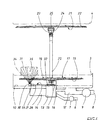
- is a front view of the flushing system of the dishwasher, with certain parts of the flushing system being schematically shown, and
- Fig. 5
- is a side view of the flushing system, with the rotatable flushing arms being rotated 90° relative to the position of
Fig. 4 . - The dishwasher according to the invention is, as can be seen from
Fig. 1 , designed with ahousing 1 which is closed in the operating state, and has ahatch 2 which can be opened for filling and emptying of the dishes which are placed in thebaskets 3, 4 (see the dotted lines inFig. 4 ) which are arranged in a lower layer and an upper layer. Thebaskets washing area 5 through the openedhatch 2, which is done by means of not shown horizontal guides which are arranged along opposing side walls of thewashing area 5. Thebaskets baskets - As is schematically shown in
Fig. 4 , the dishwasher is in a conventional manner connected to a pressurized water system via awater intake 6, with awater intake valve 7 being adjustable between an open and a closed position for the supply of water in some positions and no supply during the ongoing washing cycle. Via anoutlet conduit 8 , used water or washing liquid is removed, containing both detergent and pollutions. This is done by means of a schematically shownoutlet pump 9 which is automatically started after a finished cycle. During an ongoing washing/flushing cycle, the water or the washing liquid is circulated in thewashing area 5 in a closed system. In the closed system or circulation system, there is comprised a fluid basin which is formed by a lower container part of the machine for the collection of washing fluid, see thefluid level 10 shown with dotted lines inFig. 4 . - At the bottom of the fluid basin there is arranged a circulation well 12, from which the
outlet conduit 8 thus leads. A coarse sieve and a fine sieve cover the well opening upwards. During the washing cycles, the outlet conduit8 is closed either by means of a not shown separate outlet valve, or by means of theoutlet pump 9 blocking the outlet conduits in the inactive position - One of the other parts of the closed system or circulatory system is the
circulation pump 13 with anelectric engine 14 which is arranged to be active during the washing cycles, to circulate the washing liquid under pressure and to be controlled by a not shown control unit for the various process steps of the dishwasher. In the circulation circuit, there is comprised thecentral canal 15 which extends in the flushingarm tower 16 which supports therotatable flushing arm 17. said can be of a conventional type, and is rotatably attached about avertical axis 25 The flushingarm 12 exhibits a plurality of oblique nozzles, bothupper nozzles 18 and alsonozzles 19 directed downwards. By means of the nozzles being oblique, thearm 12 is driven around for rotation during the operating cycles when the water is pressurized by thecirculation pump 13. Via a U-shapedflushing pipe 20, the water or the washing liquid is led to an upperrotatable flushing arm 21, seeFigs. 1 ,2 ,4 and5 , which can be found in most dishwashers for floor mounting in order to, by means of upwardly and also downwardly directednozzles 22, flush the dishes in the upper basket , but to also flush the dishes in thelower basket 3 and also in a not shown cutlery 3 basket which is usually placed in thelower basket 3 Theupper arm 21 is also rotatably fixed and supported by the upper end of the flushingpipe 20 which terminates in an upper flushingarm tower 23 which both leads the water from the flushingpipe 20 to the inside of the flushingarm 21 and also supports the flushing arm's bearing about itsaxis 25. Water is also led to a cutlery flushingnozzle 24 which is arranged on the upper flushingarm tower 23 and is from above directed towards the cutlery basket for special flushing of cutlery etc. - According to the invention, there is arranged an intensive zone with a
storing surface 34 for particularly soiled dishes. To the zone, a stiff unattached flushingarm 26 leads, which consists of a stiff unattached flushingconduit 27 which at itsinner end 28 is attached to the lower flushingarm tower 16, and at its outer end supports an intense flushingnozzle 30 which is directed upwards towards thesecond dish basket 3. Thenozzle 30 is arranged at a relatively limited distance from the bottom of thebasket 3 which within a chosen zone forms thestoring surface 34 for the dishes which are represented by a pot orpan 31 which is turned upside down. The direction and influence of thenozzle 30 is thus limited to a smaller zone of the entire closedwashing area 5, as can best be seen in its entirety inFig. 1 . The flushingconduit 27 thus does not exhibit nozzles distributed across the length of the conduit, but is intended to move the flushing point or flushing zone to a location at a distance from the centre of the dishwasher where the cutlery basket is usually placed. - The flushing
arm 26 with the flushingconduit 27 is furthermore designed in a stiff material, usually a plastic pipe or a metal pipe , in order to freely support theintensive flushing nozzle 30 at a distance from the bottom or the side walls of thewashing area 5 by means of which no mechanical attachments in the wall surfaces of the dishwasher are necessary ; rather the attachment is done directly in the flushingarm tower 16 by means of theconduit 21 protruding into anattachment detail 32 which is arranged on the flushingarm tower 16. In the example shown, the flushingarm 26 is directed obliquely inwards backwards into the washing area as seen from above, in order to form a zone in essentially one of four quadrants which the bottom of thewashing area 5 can be considered to be divided into. Theintensive flushing nozzle 30 can advantageously be designed in plastic, possibly with a nozzle opening which is covered by a metal pipe , with the nozzle being screwed onto the flushingconduit 27 by means of alocking screw 23. Thepipe 22 as such is thus enclosed in its casing surface, but is open at both its ends for the intake of flushing water from thecentral canal 15 in theflushing tower 16 and for the outlet of the water to thenozzle 30. - The
intensive flushing nozzle 30 is in an advantageous example designed so that it emits a beam which diverges from thenozzle 30, so that a normal sizeddish 31 positioned directly in front of the beam is hit over a large part of its bottom surface and possibly also to a certain extent its walls. The angle of spread, and thus to a certain extent the amount of flow , also influences the intensity of the beam for which reason a suitable angle is chosen after a normal case. Examples of a possible angle range for the spreading angle is between 45° and 135°, however preferably below 75°. The optimal angle also depends on the distance of thenozzle 20 to thedishes 31, i.e. the storage level of thedish basket 3 in question, i.e. itsstoring surface 34. Examples of distances are 5-10 cm. Alternatively, it is possible that an evenly distributed beam is replaced by a plume with the shape of a conical casing, but also a highly concentrated rotating beam is possible which thus generates the shape of a conical casing surface. - In the example shown, the
free flushing arm 26 is positioned below the rotatablelower flushing arm 17, which in practice is not a problem since thearm 17 passes during such a short part of the flushing time. On the contrary, it can have a positive effect for the cleaning in that a stationary spraying pattern momentarily and recurringly is interrupted and deflected, since at the passage of thelower flushing arm 12, thebeam 35 from the flushingnozzle 30 is directed to other areas in thedish 31. - In an advantageous embodiment, the dishwasher can be provided with an alternating valve which, for example, is arranged in the
lower flushing tower 16 and which is electrically controlled to alternatingly direct the flow of liquid from the circulatingpump 13 to the lower and upper flushingarm nozzles intencive flushing nozzle 30 in case of the presence of extra soileddishes 31, but can be turned off when there are nosuch dishes 31. The alternation can also be given a relatively high frequency, so that the beams of liquid accomplish a pulsating effect which gives the liquid an extra dynamic force. - The invention is not limited to the above described examples of embodiments which have also been shown in the drawings but can be freely varied within the scope of the appended claims. It is for example possible to let the
non-attached flushing arm 26 be adjustable either by means of theinner attachment 32 making thearm 26 pivotable and/or letting thearm 26 be extendible. Thenozzle 30 can also be made rotatable about the longitudinal axis of thearm 26 for adjustment of the direction of thebeam 35. It is however essential that thearm 26 has such a stiffness that it can freely support thenozze 30, i.e. freely without any contact with the bottom or side walls, which would lead to the gathering of pollutions.
Claims (5)
- A dishwasher for batchwise washing of dishes in a washing area (5) by means of flushing of the dishes with a washing liquid by means of flushing nozzles (18, 19, 22, 24, 30) which are connected to a liquid circulation system in order to circulate the liquid by means of a circulation pump (13), and to cyclically let in and let out the circulating washing liquid, with a number of the nozzles (18,19,22) being arranged in one or several flushing arms (17, 21) rotatable about an axis (25), characterized in that the washing area (5) exhibits an intensive zone with a storing surface (34) for particularly soiled dishes (31), and an intensive flushing nozzle (30) which is arranged to direct a local beam (35) towards the intensive zone and its corresponding storing surface (34) at a distance from said flushing arm axis (25), and in that said intensive flushing nozzle (30) is fixed and attached to a stiff freely supporting flushing arm (26) which both mechanically and regarding the liquid is attached to the circulation conduit at a central canal (15) at the rotatable flushing arm (17), and in that the stiff flushing arm (26) contains a liquid conduit which connects the intensive flushing nozzle (30) with the central canal (15), so that the local beam (35) adapts a certain position and a certain direction .
- A dishwasher according to claim 1, characterized in that the flushing arm (26) of the intensive flushing nozzle (30) with its inner end (28) is attached to a flushing arm tower (16) which supports the refatable flushing arm (17) and contains the central canal (15) which communicates with the circulation pump (13).
- A dishwasher according to claim 2, characterized in that the intensive flushing nozzle (30) is arranged below the rotatable flushing arm (17).
- A dishwasher according to claim 3, characterized in that the rotatable flushing arm (17) is arranged to periodically interrupt and redirect the beam (35) from the intensive flushing nozzle (30).
- A dishwasher according to claim 1, characterized in that the storing surface (34) for particularly soiled dishes (31) consists of a chosen place in an open dish basket (3) for inlet of the beam (35) from the intensive flushing nozzle (30).
Applications Claiming Priority (3)
| Application Number | Priority Date | Filing Date | Title |
|---|---|---|---|
| SE0202590 | 2002-08-30 | ||
| SE0202590A SE524021C2 (en) | 2002-08-30 | 2002-08-30 | Dishwasher with intensive zone |
| PCT/SE2003/001347 WO2004019747A1 (en) | 2002-08-30 | 2003-08-29 | Dish washing machine |
Publications (2)
| Publication Number | Publication Date |
|---|---|
| EP1549196A1 EP1549196A1 (en) | 2005-07-06 |
| EP1549196B1 true EP1549196B1 (en) | 2011-11-02 |
Family
ID=20288867
Family Applications (1)
| Application Number | Title | Priority Date | Filing Date |
|---|---|---|---|
| EP03791537A Expired - Lifetime EP1549196B1 (en) | 2002-08-30 | 2003-08-29 | Dish washing machine |
Country Status (6)
| Country | Link |
|---|---|
| EP (1) | EP1549196B1 (en) |
| AT (1) | ATE531308T1 (en) |
| AU (1) | AU2003257746A1 (en) |
| DK (1) | DK1549196T3 (en) |
| SE (1) | SE524021C2 (en) |
| WO (1) | WO2004019747A1 (en) |
Cited By (2)
| Publication number | Priority date | Publication date | Assignee | Title |
|---|---|---|---|---|
| KR20140066857A (en) * | 2012-11-12 | 2014-06-03 | 삼성전자주식회사 | Dish washer |
| DE102018222849A1 (en) * | 2018-12-21 | 2020-06-25 | BSH Hausgeräte GmbH | Household dishwasher |
Families Citing this family (14)
| Publication number | Priority date | Publication date | Assignee | Title |
|---|---|---|---|---|
| US8691315B2 (en) | 2005-10-19 | 2014-04-08 | Hill's Pet Nutrition, Inc. | Process for preparing a food composition |
| SE531890C2 (en) | 2007-01-26 | 2009-09-01 | Gs Dev Ab | Dishwasher |
| US8007598B2 (en) | 2008-10-27 | 2011-08-30 | Whirlpool Corporation | Dishwasher having multiple spray zones |
| US8349089B2 (en) | 2008-11-07 | 2013-01-08 | Whirlpool Corporation | Dishwasher having dedicated sprayer for silverware basket |
| KR101300919B1 (en) * | 2011-07-21 | 2013-08-27 | 엘지전자 주식회사 | Dish washer |
| PL2687141T3 (en) * | 2012-07-16 | 2024-03-18 | Candy S.P.A. | A dishwasher |
| EP3030131B1 (en) | 2013-08-06 | 2020-10-07 | Arçelik Anonim Sirketi | A dishwasher with improved washing effectiveness |
| WO2015049237A1 (en) | 2013-10-03 | 2015-04-09 | Arcelik Anonim Sirketi | A dishwasher with improved washing effectiveness |
| WO2015096921A1 (en) | 2013-12-24 | 2015-07-02 | Arcelik Anonim Sirketi | A dishwasher with improved washing effectiveness |
| US11297997B2 (en) * | 2018-04-04 | 2022-04-12 | K.D.W. Company Limited | Dish washing machine with heat exchangers |
| EP3791768B1 (en) | 2019-09-16 | 2023-07-12 | Arçelik Anonim Sirketi | A dishwasher with improved washing effectiveness |
| WO2023247029A1 (en) | 2022-06-22 | 2023-12-28 | Gorenje D.O.O. | A dishwasher with improved spraying means |
| DE102022207320A1 (en) * | 2022-07-18 | 2024-01-18 | BSH Hausgeräte GmbH | Dishwasher and washware holder with expansion option |
| EP4364633A1 (en) | 2022-11-07 | 2024-05-08 | Arçelik Anonim Sirketi | A dishwasher with improved washing effectiveness |
Family Cites Families (3)
| Publication number | Priority date | Publication date | Assignee | Title |
|---|---|---|---|---|
| US3288155A (en) | 1964-09-28 | 1966-11-29 | Gen Electric | Silverware washing system |
| US3915182A (en) * | 1973-11-08 | 1975-10-28 | Tappan Co | Spray deflector for dishwashers |
| DE29607515U1 (en) * | 1996-04-25 | 1997-08-21 | AEG Hausgeräte GmbH, 90429 Nürnberg | Dishwasher with a washing compartment for arranging items to be cleaned |
-
2002
- 2002-08-30 SE SE0202590A patent/SE524021C2/en not_active IP Right Cessation
-
2003
- 2003-08-29 WO PCT/SE2003/001347 patent/WO2004019747A1/en not_active Application Discontinuation
- 2003-08-29 AT AT03791537T patent/ATE531308T1/en active
- 2003-08-29 AU AU2003257746A patent/AU2003257746A1/en not_active Abandoned
- 2003-08-29 EP EP03791537A patent/EP1549196B1/en not_active Expired - Lifetime
- 2003-08-29 DK DK03791537.8T patent/DK1549196T3/en active
Cited By (2)
| Publication number | Priority date | Publication date | Assignee | Title |
|---|---|---|---|---|
| KR20140066857A (en) * | 2012-11-12 | 2014-06-03 | 삼성전자주식회사 | Dish washer |
| DE102018222849A1 (en) * | 2018-12-21 | 2020-06-25 | BSH Hausgeräte GmbH | Household dishwasher |
Also Published As
| Publication number | Publication date |
|---|---|
| SE0202590L (en) | 2004-03-01 |
| AU2003257746A1 (en) | 2004-03-19 |
| DK1549196T3 (en) | 2012-01-30 |
| ATE531308T1 (en) | 2011-11-15 |
| WO2004019747A1 (en) | 2004-03-11 |
| EP1549196A1 (en) | 2005-07-06 |
| SE524021C2 (en) | 2004-06-15 |
| SE0202590D0 (en) | 2002-08-30 |
Similar Documents
| Publication | Publication Date | Title |
|---|---|---|
| EP1549196B1 (en) | Dish washing machine | |
| CN104224073B (en) | For cleaning rotation spray arm and the application thereof of device | |
| US8721804B2 (en) | Dishwasher with auxiliary washing agent dispensing system | |
| US20090101185A1 (en) | Low-water-consumption rinsing and/or washing device, and dishwashing machine featuring such a device | |
| US20080116294A1 (en) | Spray devices and nozzles | |
| US11612298B2 (en) | Dishwasher with high-velocity sprayer | |
| US20040255992A1 (en) | Dishwasher | |
| EP1568304B1 (en) | Dishwasher | |
| TWI254624B (en) | Dish washing machine | |
| KR102493157B1 (en) | Dish Washer | |
| CN213189404U (en) | T-shaped rotary spraying arm and dish washing machine | |
| CN205359391U (en) | Basin formula cleaning device's clean system of circulation | |
| AU2017437705B2 (en) | Dishwasher spray arm assembly | |
| KR20060013790A (en) | A dish washer equipped with concentrating injection function | |
| KR20220056415A (en) | Dish washer | |
| EP0727182B1 (en) | Dishwasher with superposed baskets | |
| KR950009984B1 (en) | Washing or ringing machines for crockery with stationary crockery baskets and spraying devices within the cleaning chamber | |
| JP4146771B2 (en) | Dishwasher | |
| GB2033737A (en) | Dish washing machine | |
| JP3011014B2 (en) | Dishwashing equipment | |
| CN211796290U (en) | Cleaning machine | |
| JPS6041903Y2 (en) | tableware rinsing device | |
| KR940007663Y1 (en) | Apparatus for controlling waterflow of tableware washing machine | |
| JP3031163B2 (en) | Dishwashing equipment | |
| CN117752272A (en) | Waterway system of dish washing machine and dish washing machine |
Legal Events
| Date | Code | Title | Description |
|---|---|---|---|
| PUAI | Public reference made under article 153(3) epc to a published international application that has entered the european phase |
Free format text: ORIGINAL CODE: 0009012 |
|
| 17P | Request for examination filed |
Effective date: 20050318 |
|
| AK | Designated contracting states |
Kind code of ref document: A1 Designated state(s): AT BE BG CH CY CZ DE DK EE ES FI FR GB GR HU IE IT LI LU MC NL PT RO SE SI SK TR |
|
| AX | Request for extension of the european patent |
Extension state: AL LT LV MK |
|
| DAX | Request for extension of the european patent (deleted) | ||
| 17Q | First examination report despatched |
Effective date: 20100209 |
|
| GRAP | Despatch of communication of intention to grant a patent |
Free format text: ORIGINAL CODE: EPIDOSNIGR1 |
|
| GRAS | Grant fee paid |
Free format text: ORIGINAL CODE: EPIDOSNIGR3 |
|
| GRAA | (expected) grant |
Free format text: ORIGINAL CODE: 0009210 |
|
| AK | Designated contracting states |
Kind code of ref document: B1 Designated state(s): AT BE BG CH CY CZ DE DK EE ES FI FR GB GR HU IE IT LI LU MC NL PT RO SE SI SK TR |
|
| REG | Reference to a national code |
Ref country code: GB Ref legal event code: FG4D |
|
| REG | Reference to a national code |
Ref country code: CH Ref legal event code: EP |
|
| REG | Reference to a national code |
Ref country code: IE Ref legal event code: FG4D |
|
| REG | Reference to a national code |
Ref country code: DE Ref legal event code: R096 Ref document number: 60339007 Country of ref document: DE Effective date: 20111229 |
|
| REG | Reference to a national code |
Ref country code: NL Ref legal event code: T3 |
|
| REG | Reference to a national code |
Ref country code: DK Ref legal event code: T3 |
|
| PG25 | Lapsed in a contracting state [announced via postgrant information from national office to epo] |
Ref country code: PT Free format text: LAPSE BECAUSE OF FAILURE TO SUBMIT A TRANSLATION OF THE DESCRIPTION OR TO PAY THE FEE WITHIN THE PRESCRIBED TIME-LIMIT Effective date: 20120302 Ref country code: SE Free format text: LAPSE BECAUSE OF FAILURE TO SUBMIT A TRANSLATION OF THE DESCRIPTION OR TO PAY THE FEE WITHIN THE PRESCRIBED TIME-LIMIT Effective date: 20111102 Ref country code: GR Free format text: LAPSE BECAUSE OF FAILURE TO SUBMIT A TRANSLATION OF THE DESCRIPTION OR TO PAY THE FEE WITHIN THE PRESCRIBED TIME-LIMIT Effective date: 20120203 Ref country code: SI Free format text: LAPSE BECAUSE OF FAILURE TO SUBMIT A TRANSLATION OF THE DESCRIPTION OR TO PAY THE FEE WITHIN THE PRESCRIBED TIME-LIMIT Effective date: 20111102 Ref country code: BE Free format text: LAPSE BECAUSE OF FAILURE TO SUBMIT A TRANSLATION OF THE DESCRIPTION OR TO PAY THE FEE WITHIN THE PRESCRIBED TIME-LIMIT Effective date: 20111102 |
|
| PG25 | Lapsed in a contracting state [announced via postgrant information from national office to epo] |
Ref country code: CY Free format text: LAPSE BECAUSE OF FAILURE TO SUBMIT A TRANSLATION OF THE DESCRIPTION OR TO PAY THE FEE WITHIN THE PRESCRIBED TIME-LIMIT Effective date: 20111102 |
|
| PG25 | Lapsed in a contracting state [announced via postgrant information from national office to epo] |
Ref country code: EE Free format text: LAPSE BECAUSE OF FAILURE TO SUBMIT A TRANSLATION OF THE DESCRIPTION OR TO PAY THE FEE WITHIN THE PRESCRIBED TIME-LIMIT Effective date: 20111102 Ref country code: CZ Free format text: LAPSE BECAUSE OF FAILURE TO SUBMIT A TRANSLATION OF THE DESCRIPTION OR TO PAY THE FEE WITHIN THE PRESCRIBED TIME-LIMIT Effective date: 20111102 Ref country code: BG Free format text: LAPSE BECAUSE OF FAILURE TO SUBMIT A TRANSLATION OF THE DESCRIPTION OR TO PAY THE FEE WITHIN THE PRESCRIBED TIME-LIMIT Effective date: 20120202 Ref country code: SK Free format text: LAPSE BECAUSE OF FAILURE TO SUBMIT A TRANSLATION OF THE DESCRIPTION OR TO PAY THE FEE WITHIN THE PRESCRIBED TIME-LIMIT Effective date: 20111102 |
|
| PG25 | Lapsed in a contracting state [announced via postgrant information from national office to epo] |
Ref country code: IT Free format text: LAPSE BECAUSE OF FAILURE TO SUBMIT A TRANSLATION OF THE DESCRIPTION OR TO PAY THE FEE WITHIN THE PRESCRIBED TIME-LIMIT Effective date: 20111102 Ref country code: RO Free format text: LAPSE BECAUSE OF FAILURE TO SUBMIT A TRANSLATION OF THE DESCRIPTION OR TO PAY THE FEE WITHIN THE PRESCRIBED TIME-LIMIT Effective date: 20111102 |
|
| PLBE | No opposition filed within time limit |
Free format text: ORIGINAL CODE: 0009261 |
|
| STAA | Information on the status of an ep patent application or granted ep patent |
Free format text: STATUS: NO OPPOSITION FILED WITHIN TIME LIMIT |
|
| REG | Reference to a national code |
Ref country code: AT Ref legal event code: MK05 Ref document number: 531308 Country of ref document: AT Kind code of ref document: T Effective date: 20111102 |
|
| 26N | No opposition filed |
Effective date: 20120803 |
|
| REG | Reference to a national code |
Ref country code: DE Ref legal event code: R097 Ref document number: 60339007 Country of ref document: DE Effective date: 20120803 |
|
| PG25 | Lapsed in a contracting state [announced via postgrant information from national office to epo] |
Ref country code: AT Free format text: LAPSE BECAUSE OF FAILURE TO SUBMIT A TRANSLATION OF THE DESCRIPTION OR TO PAY THE FEE WITHIN THE PRESCRIBED TIME-LIMIT Effective date: 20111102 |
|
| REG | Reference to a national code |
Ref country code: CH Ref legal event code: PL |
|
| PG25 | Lapsed in a contracting state [announced via postgrant information from national office to epo] |
Ref country code: MC Free format text: LAPSE BECAUSE OF NON-PAYMENT OF DUE FEES Effective date: 20120831 |
|
| GBPC | Gb: european patent ceased through non-payment of renewal fee |
Effective date: 20120829 |
|
| PG25 | Lapsed in a contracting state [announced via postgrant information from national office to epo] |
Ref country code: ES Free format text: LAPSE BECAUSE OF FAILURE TO SUBMIT A TRANSLATION OF THE DESCRIPTION OR TO PAY THE FEE WITHIN THE PRESCRIBED TIME-LIMIT Effective date: 20120213 Ref country code: CH Free format text: LAPSE BECAUSE OF NON-PAYMENT OF DUE FEES Effective date: 20120831 Ref country code: LI Free format text: LAPSE BECAUSE OF NON-PAYMENT OF DUE FEES Effective date: 20120831 |
|
| REG | Reference to a national code |
Ref country code: FR Ref legal event code: ST Effective date: 20130430 |
|
| REG | Reference to a national code |
Ref country code: IE Ref legal event code: MM4A |
|
| PG25 | Lapsed in a contracting state [announced via postgrant information from national office to epo] |
Ref country code: DE Free format text: LAPSE BECAUSE OF NON-PAYMENT OF DUE FEES Effective date: 20130301 Ref country code: GB Free format text: LAPSE BECAUSE OF NON-PAYMENT OF DUE FEES Effective date: 20120829 Ref country code: IE Free format text: LAPSE BECAUSE OF NON-PAYMENT OF DUE FEES Effective date: 20120829 |
|
| PG25 | Lapsed in a contracting state [announced via postgrant information from national office to epo] |
Ref country code: FR Free format text: LAPSE BECAUSE OF NON-PAYMENT OF DUE FEES Effective date: 20120831 |
|
| REG | Reference to a national code |
Ref country code: DE Ref legal event code: R119 Ref document number: 60339007 Country of ref document: DE Effective date: 20130301 |
|
| PG25 | Lapsed in a contracting state [announced via postgrant information from national office to epo] |
Ref country code: TR Free format text: LAPSE BECAUSE OF FAILURE TO SUBMIT A TRANSLATION OF THE DESCRIPTION OR TO PAY THE FEE WITHIN THE PRESCRIBED TIME-LIMIT Effective date: 20111102 |
|
| PG25 | Lapsed in a contracting state [announced via postgrant information from national office to epo] |
Ref country code: LU Free format text: LAPSE BECAUSE OF NON-PAYMENT OF DUE FEES Effective date: 20120829 |
|
| PG25 | Lapsed in a contracting state [announced via postgrant information from national office to epo] |
Ref country code: HU Free format text: LAPSE BECAUSE OF FAILURE TO SUBMIT A TRANSLATION OF THE DESCRIPTION OR TO PAY THE FEE WITHIN THE PRESCRIBED TIME-LIMIT Effective date: 20030829 |
|
| PGFP | Annual fee paid to national office [announced via postgrant information from national office to epo] |
Ref country code: NL Payment date: 20190826 Year of fee payment: 17 |
|
| PGFP | Annual fee paid to national office [announced via postgrant information from national office to epo] |
Ref country code: FI Payment date: 20190826 Year of fee payment: 17 Ref country code: DK Payment date: 20190827 Year of fee payment: 17 |
|
| REG | Reference to a national code |
Ref country code: FI Ref legal event code: MAE |
|
| REG | Reference to a national code |
Ref country code: DK Ref legal event code: EBP Effective date: 20200831 |
|
| REG | Reference to a national code |
Ref country code: NL Ref legal event code: MM Effective date: 20200901 |
|
| PG25 | Lapsed in a contracting state [announced via postgrant information from national office to epo] |
Ref country code: FI Free format text: LAPSE BECAUSE OF NON-PAYMENT OF DUE FEES Effective date: 20200829 |
|
| PG25 | Lapsed in a contracting state [announced via postgrant information from national office to epo] |
Ref country code: DK Free format text: LAPSE BECAUSE OF NON-PAYMENT OF DUE FEES Effective date: 20200831 |
|
| PG25 | Lapsed in a contracting state [announced via postgrant information from national office to epo] |
Ref country code: NL Free format text: LAPSE BECAUSE OF NON-PAYMENT OF DUE FEES Effective date: 20200901 |