EP1549129B1 - Zuführvorrichtung für einen baumernter - Google Patents
Zuführvorrichtung für einen baumernter Download PDFInfo
- Publication number
- EP1549129B1 EP1549129B1 EP03798941A EP03798941A EP1549129B1 EP 1549129 B1 EP1549129 B1 EP 1549129B1 EP 03798941 A EP03798941 A EP 03798941A EP 03798941 A EP03798941 A EP 03798941A EP 1549129 B1 EP1549129 B1 EP 1549129B1
- Authority
- EP
- European Patent Office
- Prior art keywords
- feeder device
- links
- rollers
- rolling
- timber harvester
- Prior art date
- Legal status (The legal status is an assumption and is not a legal conclusion. Google has not performed a legal analysis and makes no representation as to the accuracy of the status listed.)
- Expired - Lifetime
Links
Images
Classifications
-
- B—PERFORMING OPERATIONS; TRANSPORTING
- B27—WORKING OR PRESERVING WOOD OR SIMILAR MATERIAL; NAILING OR STAPLING MACHINES IN GENERAL
- B27B—SAWS FOR WOOD OR SIMILAR MATERIAL; COMPONENTS OR ACCESSORIES THEREFOR
- B27B25/00—Feeding devices for timber in saw mills or sawing machines; Feeding devices for trees
- B27B25/04—Feeding devices for timber in saw mills or sawing machines; Feeding devices for trees with feed chains or belts
-
- A—HUMAN NECESSITIES
- A01—AGRICULTURE; FORESTRY; ANIMAL HUSBANDRY; HUNTING; TRAPPING; FISHING
- A01G—HORTICULTURE; CULTIVATION OF VEGETABLES, FLOWERS, RICE, FRUIT, VINES, HOPS OR SEAWEED; FORESTRY; WATERING
- A01G23/00—Forestry
- A01G23/02—Transplanting, uprooting, felling or delimbing trees
- A01G23/08—Felling trees
- A01G23/083—Feller-delimbers
Definitions
- the present invention relates to a feeder device for a timber harvester, which feeder device includes a 3-row roller chain arranged to be rotated around a drive sprocket, a turnover member and rolling guides, which extend over a great length of the gripping side between the drive sprocket and the turnover member, and in which roller chain there are rows of links staggered relative to each other by transverse pins, comprising a middle row of links and outer rows of links, each row of links including rollers rolling in the corresponding rolling guides and set in bearings in the transverse pins, and in which the drive sprocket is arranged to drive by its teeth the middle row of links of the roller chain through its rollers.
- the term 'timber harvester' must be understood quite broadly as encompassing very different kinds of devices for handling fibre and log timber.
- a timber harvester feeder device is known from the applicant's previous publications WO 85/05589 and WO 99/25526 , which correspond to US-A -4 753 338 and to US- B1-6 202 719 respectively.
- a timber harvester usually has two feed tracks jointed oppositely to each other, stripping blades, and a cutting device.
- the frame of the feed track is installed on articulated arms.
- the roller chain is fitted around a drive sprocket, driving the middle row of links, and a turnover member, generally a pair of idler wheels.
- the dimensions of the roller chain are adapted to the dimension of the toothing of the drive sprocket, which has limited the diameter of the rollers.
- a track feed has obvious advantages over drive rollers.
- the first publication deals with a situation, in which rolling bases and roller chains are used. This substantially improves the durability of the track feed, as the solution allows the loading to be transferred directly to the sliding base, thus avoiding loading peaks in the track.
- the latter publication discloses a curved rolling base, so that the track-feed device imitates a large drive roller, the length of the grip with the timber being much longer than in any real drive roller, the diameter of which remains much smaller for practical reasons. Due to the curved rolling base, the mechanism is simplified, as one joint of the feed device can be eliminated.
- a crawler track is a special roller chain, in which the rollers and pins wear in use. In order to reduce friction, the rollers are equipped with bushings.
- the rolling bases wear in use and, like the crawler track, are preferably made to be replaceable. In known rolling bases, grooves must be machined between the rollers, to prevent the links from coming in contact with the base.
- the present invention is intended to create an improved feeder device for a timber harvester, which will have a long operating life and excellent reliability.
- the feeder device is an essential component in a timber harvester and has a significant effect on the total weight of the entire machine.
- the invention is intended to reduce the size of and weight of the track feeder device, without impairing its durability.
- the row in the middle of the track generally does not wear, even though it is subjected to the stress of the drive sprocket driving the track. Therefore the outer rows of links can, in fact, be equipped with larger rollers, provided that the rolling base is also adapted to rollers of different sizes.
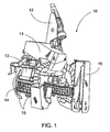
- Figure 1 shows one timber harvester 10, which includes a frame 11, a suspension device 12, two feed tracks 14 jointed oppositely to each other, stripping blades 15, and a cutting device 16 (a saw).
- the feed tracks 14 and the stripping blades 15 are operated with the aid of hydraulic cylinders (not shown) and they press the tree being processed into their throat.
- the feed tracks 14 pull the tree through the throat.
- the frame of the feed track 14 is installed on articulated arms 13.
- the feed track 14 is a 3-row roller chain fitted around a drive sprocket, a turnover member, and rolling guides, which extend over a great length of the gripping side, between the drive sprocket and the turnover member.
- the weight of the timber harvester can be reduced by making smaller crawler-track feeder devices.
- the pressure, on the surface of the timber, of a crawler track rolling even on a curved base is not too great, even though the contact surface between the track and the timber is shorter than in a feeder device equipped with a straight rolling base.
- the reduction in weight is therefore limited only by the surface pressure between the crawler track and its base and subsequently by the wear of their components that roll mutually relative to each other.
- the crawler track is a 3-row track.
- the chain can be a traditional 3-row roller chain, in which the links are next to each other, they are preferably staggered relative to each other ( WO 85/05589 ), in order to equalize the loading.
- the drive sprocket is located at the middle row, so that the dimensions of the construction of this row is based on the drive event.
- Both the outer rows of the crawler track are, in turn, equipped with rollers of the greater possible diameter. This creates a 3-row crawler track, in which the diameter of the rollers of the inner row is a maximum of 80 % of their spacing and usually less.
- the rollers of the outer rows have a diameter that is at least 85 % of the spacing of the elements of the crawler track.
- the roller diameter of the inner row of the roller chains is about 70 % of the spacing.
- a diameter that is 85 - 95 % of the spacing can be preferably used.
- the outer rollers 33.1 have a diameter 10 - 25% greater than that of the middle rollers 34.1.
- at least the outer rollers 33.1 are equipped with bushings 33.3.
- the rolling base (except for the middle row) can also be advantageously made in the form of plates, without separate rails. As the rollers of the outer rows are large, the outer surface of the roller is pushed outside of the outer surface of the side plates. No space is then required on the rolling base for the side plates of the outer rows.
- a rolling base of this kind can be manufactured effectively using large blades, even though more material must be removed than in a base equipped with grooves.
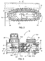
- FIG. 2 shows one construction of feeder device 14 (cross-section B - B, Figure 3).
- the feeder device which is seen in part cross-section from the side, is equipped with a curved rolling base 22.
- the tree being processed is marked with the reference number 1.
- the crawler track is marked generally with the reference number 17 and is driven by a drive sprocket 24. At the opposite end, it travels around two idlers 25, which are, however, narrow in the area of the outer rollers and preferably have truncated teeth.
- the idler can, however, also be smooth, or be replaced entirely with a rolling guide.
- the teeth 24.1 of the drive sprocket 24 transmit power to the middle row of links of the crawler track 17.
- the need for these teeth 24.1 to fit between the opposing rollers limits the size of the rollers relative to their spacing. This limitation does not apply to the outer rows of links, and in them the diameter of the rollers can approach the dimension of their spacing.
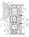
- Figure 3 shows a top view of the feeder device 14, with the crawler track 17 nearly entirely removed and partly cut open.
- the figure shows the rolling base 22, the drive sprocket 24, the hydraulic motor 19 that rotates it, the suspension arm 13.2 of the feeder device, the suspension joint 19, and the idlers 25.
- the crawler track 17 fills the space between the side plates 14.2 of the frame with a small tolerance.
- the crawler track 17 is staggered according to the figure.
- the pin 17.4 locked to the side plates 17.3 of the crawler track 17 secures the links 33.2 and 34.2 in such a way that the links 34.2 of the middle row 17.2 are 'in the same phase' as side plates 33.2, while the links 33.2 of the outer rows of links 17.1 are staggered relative to them.
- the detachable rolling base 22 is substantially narrower than the crawler track 17, so that at least the side plates 17.3 have plenty of space to move.
- Figure 4 shows a cross-section of the feeder device, at the point A - A in Figure 2.
- the components 33.2 and 34.2 show the links of a 3-row chain.
- Component 17.3 is the side plate on both sides of the crawler track 17, i.e. the pin 17.4 is attached to them at both ends.
- the links 33.3 and 34.3 are formed in a known manner from U-shaped pieces, with grip studs welded to the web.
- the links can also be made from separate side plates, with a web plate welded across their ends.
- the gripping members can be a stud welded onto the web plate, or a plate-like piece.
- roller 33.1 in the links 33.2 is larger than the roller 34.1 in the link 34.2. These correspond to the rolling bands 22.1 and 22.2 of the rolling base.
- the rolling base 22 is otherwise uniform, but is thicker under the middle row, to raise the rolling band 22.2 to correspond to the smaller roller 34.1.
- the rolling base can also be partial and divided (not shown). In this case, bolts 22.3 are used to make it detachable, but a welded joint can also be used.
- the rolling guides are preferably curved, with their curvature corresponding to a radius of about 1 metre, usually 0,8 - 1,3 m. The durability, mechanical operation, and adhesion properties will then be optimal.
- Carbon tempering increases the low surface carbon content of steel to the level 0,65 - 0,9 %, in order to improve its hardenability and achieve a high surface hardness.
- the thickness of the carbonization layer is preferably in the range of 1 2,5 mm.
- the basic construction of the timber harvester can even deviate greatly from the example shown.
- the term timber harvester refers to a single-grab harvester, in which there are two opposing feeder devices, the basic construction of which is shown in the said PCT publication WO 99/25526 .
Landscapes
- Life Sciences & Earth Sciences (AREA)
- Forests & Forestry (AREA)
- Biodiversity & Conservation Biology (AREA)
- Ecology (AREA)
- Environmental Sciences (AREA)
- Engineering & Computer Science (AREA)
- Mechanical Engineering (AREA)
- Wood Science & Technology (AREA)
- Rollers For Roller Conveyors For Transfer (AREA)
- Paper (AREA)
- Harvesting Machines For Root Crops (AREA)
- Organic Low-Molecular-Weight Compounds And Preparation Thereof (AREA)
- Fertilizers (AREA)
- Inorganic Insulating Materials (AREA)
- Constituent Portions Of Griding Lathes, Driving, Sensing And Control (AREA)
- Chain Conveyers (AREA)
- Debarking, Splitting, And Disintegration Of Timber (AREA)
Claims (9)
- Für eine Holzerntemaschine bestimmte Vorschubvorrichtung, die einen Rahmen (21) und eine Dreifachrollenkette (17) umfasst, die, von einem Antriebsrad (24) gezogen, über ein Wendeglied (25) und über Wälzführungen (22.1, 22.2), die sich eingriffseitig über eine große Länge zwischen Antriebsrad (24) und Wendeglied (25) erstrecken, läuft, wobei die Rollenkette (17) gegeneinander versetzte, durch Querbolzen (17.4) aneinander gebundene Gliederreihen bestehend aus einer mittleren Gliederreihe (17.2) und aus äußeren Gliederreihen (17.1) umfasst, und jede Gliederreihe auf der entsprechenden Wälzführung (22.1, 22.2) rollende, an den Querbolzen gelagerte Rollen (33.1, 34.1) hat, und das Antriebsrad (24) mit seinen Zähnen (24.1) die mittlere Gliederreihe (17.2) der Rollenkette (17) über deren Rollen (34.1) antreibt, dadurch gekennzeichnet, dass die äußeren Gliederreihen (17.1) der Rollenkette (17) mit Rollen (33.1) von größerem Durchmesser als die Rollen (34.1) der mittleren Gliederreihe (17.2) bestückt sind, wobei die mittlere Wälzführung (22.2) im Vergleich zu den äußeren Wälzführungen (22.1) entsprechend erhöht ist.
- Für eine Holzerntemaschine bestimmte Vorschubvorrichtung (14) nach Anspruch 1, dadurch gekennzeichnet, dass die äußeren Rollen (33.1) einen um 10-25 % größeren Durchmesser als die mittleren Rollen (34.1) haben.
- Für eine Holzerntemaschine bestimmte Vorschubvorrichtung (14) nach Anspruch 1 oder 2, dadurch gekennzeichnet, dass der Durchmesser der äußeren Rollen (33.1) 85-95 % der Teilung beträgt.
- Für eine Holzerntemaschine bestimmte Vorschubvorrichtung (14) nach irgendeinem der Ansprüche 1 bis 3, dadurch gekennzeichnet, dass zumindest die äußeren Rollen (33.1 mit Buchsen (33.3) versehen sind.
- Für eine Holzerntemaschine bestimmte Vorschubvorrichtung (14) nach irgendeinem der Ansprüche 1 bis 4, dadurch gekennzeichnet, dass die äußeren Wälzführungen (22.1) sich seitlich betrachtet wesentlich in den Bereich des Antriebsrades erstrecken.
- Für eine Holzerntemaschine bestimmte Vorschubvorrichtung (14) nach irgendeinem der Ansprüche 1 bis 5, dadurch gekennzeichnet, dass die Wälzführungen (22.1, 22.2) einen gemeinsamen Verschleißkörper (22) bilden, der demontierbar am Rahmen (14.1) der Vorschubvorrichtung befestigt ist.
- Für eine Holzerntemaschine bestimmte Vorschubvorrichtung (14) nach Anspruch 6, dadurch gekennzeichnet, dass der die Wälzführungen (22.1, 22.2) bildende Verschleißkörper (22) zumindest an den Verschleißflächen einsatzgehärtet ist.
- Für eine Holzerntemaschine bestimmte Vorschubvorrichtung (14) nach Anspruch 6 oder 7, dadurch gekennzeichnet, dass die Gesamtbreite der Wälzführungen (22.1, 22.2) geringer ist als die von den Laschen (17.3) der Raupenkette (17) eingeschlossene Breite.
- Für eine Holzerntemaschine bestimmte Vorschubvorrichtung (14) nach irgendeinem der Ansprüche 1 bis 8, dadurch gekennzeichnet, dass die Wälzführungen (22.1, 22.2) gekrümmt sind und ihre Krümmung einem Radius von 0,8 bis 1,3 m entspricht.
Applications Claiming Priority (3)
| Application Number | Priority Date | Filing Date | Title |
|---|---|---|---|
| FI20021770A FI20021770A7 (fi) | 2002-10-04 | 2002-10-04 | Syöttölaite puunkorjuukoneessa |
| FI20021770 | 2002-10-04 | ||
| PCT/FI2003/000680 WO2004030443A1 (en) | 2002-10-04 | 2003-09-18 | Feeder device in a timber harvester |
Publications (2)
| Publication Number | Publication Date |
|---|---|
| EP1549129A1 EP1549129A1 (de) | 2005-07-06 |
| EP1549129B1 true EP1549129B1 (de) | 2007-10-24 |
Family
ID=8564701
Family Applications (1)
| Application Number | Title | Priority Date | Filing Date |
|---|---|---|---|
| EP03798941A Expired - Lifetime EP1549129B1 (de) | 2002-10-04 | 2003-09-18 | Zuführvorrichtung für einen baumernter |
Country Status (9)
| Country | Link |
|---|---|
| US (1) | US7185686B2 (de) |
| EP (1) | EP1549129B1 (de) |
| JP (1) | JP4339794B2 (de) |
| AT (1) | ATE376353T1 (de) |
| AU (1) | AU2003262604A1 (de) |
| CA (1) | CA2497342C (de) |
| DE (1) | DE60317086T2 (de) |
| FI (1) | FI20021770A7 (de) |
| WO (1) | WO2004030443A1 (de) |
Families Citing this family (3)
| Publication number | Priority date | Publication date | Assignee | Title |
|---|---|---|---|---|
| US7677279B2 (en) * | 2007-01-31 | 2010-03-16 | Deere & Company | Delimb knife mounting arrangement for tree harvester head |
| US11785902B2 (en) * | 2016-10-21 | 2023-10-17 | Lauri Ketonen | Feeding apparatus for a tree harvester |
| JP7584362B2 (ja) * | 2021-06-30 | 2024-11-15 | イワフジ工業株式会社 | 樹木処理装置 |
Family Cites Families (4)
| Publication number | Priority date | Publication date | Assignee | Title |
|---|---|---|---|---|
| FI69233C (fi) * | 1984-05-29 | 1986-01-10 | Lauri Ketonen | Mataranordning foer skoerdare |
| SE467102B (sv) * | 1988-04-13 | 1992-05-25 | Jan Eriksson | Drivanordning |
| SE510677C2 (sv) * | 1995-07-17 | 1999-06-14 | Plustech Oy | Trädmatningsanordning för en trädhanteringsmaskin |
| FI103010B (fi) * | 1997-11-14 | 1999-04-15 | Ketonen Lauri | Puunkorjuukone ja siinä käytettävä syöttötela |
-
2002
- 2002-10-04 FI FI20021770A patent/FI20021770A7/fi unknown
-
2003
- 2003-09-18 AU AU2003262604A patent/AU2003262604A1/en not_active Abandoned
- 2003-09-18 EP EP03798941A patent/EP1549129B1/de not_active Expired - Lifetime
- 2003-09-18 JP JP2004540833A patent/JP4339794B2/ja not_active Expired - Lifetime
- 2003-09-18 WO PCT/FI2003/000680 patent/WO2004030443A1/en not_active Ceased
- 2003-09-18 AT AT03798941T patent/ATE376353T1/de active
- 2003-09-18 US US10/526,101 patent/US7185686B2/en not_active Expired - Lifetime
- 2003-09-18 DE DE60317086T patent/DE60317086T2/de not_active Expired - Lifetime
- 2003-09-18 CA CA2497342A patent/CA2497342C/en not_active Expired - Lifetime
Also Published As
| Publication number | Publication date |
|---|---|
| US7185686B2 (en) | 2007-03-06 |
| JP2006500939A (ja) | 2006-01-12 |
| ATE376353T1 (de) | 2007-11-15 |
| EP1549129A1 (de) | 2005-07-06 |
| DE60317086T2 (de) | 2008-07-31 |
| FI20021770A7 (fi) | 2002-10-04 |
| WO2004030443A1 (en) | 2004-04-15 |
| CA2497342A1 (en) | 2004-04-15 |
| JP4339794B2 (ja) | 2009-10-07 |
| AU2003262604A1 (en) | 2004-04-23 |
| DE60317086D1 (de) | 2007-12-06 |
| CA2497342C (en) | 2011-11-29 |
| US20060086414A1 (en) | 2006-04-27 |
Similar Documents
| Publication | Publication Date | Title |
|---|---|---|
| EP2081741B1 (de) | Kettensägenverbindung mit versetztem ansatz | |
| US20080284245A1 (en) | Machine track system and machine track segment | |
| US9409310B2 (en) | Combined feed roller and conveyor sprocket/pulley for a tree chipper | |
| US9446805B2 (en) | Track assembly having arcuate crawler shoes | |
| WO2016028721A1 (en) | Track assembly having dual-sprocket drive wheel | |
| EP1549129B1 (de) | Zuführvorrichtung für einen baumernter | |
| US4753338A (en) | Feeder apparatus for timber harvesters | |
| US5735325A (en) | Tree feeding device of a tree handling machine | |
| EP1037730B1 (de) | Baumernter und seine baumzuführvorrichtung | |
| FI102051B (fi) | Terälaippa konekäyttöisiä ketjusahoja varten | |
| JP7584362B2 (ja) | 樹木処理装置 | |
| CA2262230C (en) | Feed roller | |
| US20240301523A1 (en) | Ultra-deep induction hardening for track pads | |
| US20240270331A1 (en) | Composite track pad | |
| FI97111C (fi) | Liikkuvan puunkäsittelykoneen puunsyöttölaite | |
| WO2025226705A1 (en) | Cast infeed conveyor chain | |
| CA1168182A (en) | Log feed conveyor | |
| SU898076A1 (ru) | Исполнительный орган камнерезной машины М.С.Григор на | |
| AU1680597A (en) | Chainsaw guide bar |
Legal Events
| Date | Code | Title | Description |
|---|---|---|---|
| PUAI | Public reference made under article 153(3) epc to a published international application that has entered the european phase |
Free format text: ORIGINAL CODE: 0009012 |
|
| 17P | Request for examination filed |
Effective date: 20050420 |
|
| AK | Designated contracting states |
Kind code of ref document: A1 Designated state(s): AT BE BG CH CY CZ DE DK EE ES FI FR GB GR HU IE IT LI LU MC NL PT RO SE SI SK TR |
|
| AX | Request for extension of the european patent |
Extension state: AL LT LV MK |
|
| DAX | Request for extension of the european patent (deleted) | ||
| RTI1 | Title (correction) |
Free format text: FEEDER DEVICE FOR A TIMBER HARVESTER |
|
| GRAP | Despatch of communication of intention to grant a patent |
Free format text: ORIGINAL CODE: EPIDOSNIGR1 |
|
| RAP1 | Party data changed (applicant data changed or rights of an application transferred) |
Owner name: KETONEN, LAURI |
|
| RIN1 | Information on inventor provided before grant (corrected) |
Inventor name: KETONEN, LAURI |
|
| GRAS | Grant fee paid |
Free format text: ORIGINAL CODE: EPIDOSNIGR3 |
|
| GRAA | (expected) grant |
Free format text: ORIGINAL CODE: 0009210 |
|
| AK | Designated contracting states |
Kind code of ref document: B1 Designated state(s): AT BE BG CH CY CZ DE DK EE ES FI FR GB GR HU IE IT LI LU MC NL PT RO SE SI SK TR |
|
| REG | Reference to a national code |
Ref country code: GB Ref legal event code: FG4D |
|
| REG | Reference to a national code |
Ref country code: CH Ref legal event code: EP |
|
| REG | Reference to a national code |
Ref country code: IE Ref legal event code: FG4D |
|
| REF | Corresponds to: |
Ref document number: 60317086 Country of ref document: DE Date of ref document: 20071206 Kind code of ref document: P |
|
| REG | Reference to a national code |
Ref country code: SE Ref legal event code: TRGR |
|
| NLV1 | Nl: lapsed or annulled due to failure to fulfill the requirements of art. 29p and 29m of the patents act | ||
| PG25 | Lapsed in a contracting state [announced via postgrant information from national office to epo] |
Ref country code: CH Free format text: LAPSE BECAUSE OF FAILURE TO SUBMIT A TRANSLATION OF THE DESCRIPTION OR TO PAY THE FEE WITHIN THE PRESCRIBED TIME-LIMIT Effective date: 20071024 Ref country code: NL Free format text: LAPSE BECAUSE OF FAILURE TO SUBMIT A TRANSLATION OF THE DESCRIPTION OR TO PAY THE FEE WITHIN THE PRESCRIBED TIME-LIMIT Effective date: 20071024 Ref country code: LI Free format text: LAPSE BECAUSE OF FAILURE TO SUBMIT A TRANSLATION OF THE DESCRIPTION OR TO PAY THE FEE WITHIN THE PRESCRIBED TIME-LIMIT Effective date: 20071024 Ref country code: ES Free format text: LAPSE BECAUSE OF FAILURE TO SUBMIT A TRANSLATION OF THE DESCRIPTION OR TO PAY THE FEE WITHIN THE PRESCRIBED TIME-LIMIT Effective date: 20080204 |
|
| REG | Reference to a national code |
Ref country code: CH Ref legal event code: PL |
|
| ET | Fr: translation filed | ||
| PG25 | Lapsed in a contracting state [announced via postgrant information from national office to epo] |
Ref country code: BG Free format text: LAPSE BECAUSE OF FAILURE TO SUBMIT A TRANSLATION OF THE DESCRIPTION OR TO PAY THE FEE WITHIN THE PRESCRIBED TIME-LIMIT Effective date: 20080124 Ref country code: PT Free format text: LAPSE BECAUSE OF FAILURE TO SUBMIT A TRANSLATION OF THE DESCRIPTION OR TO PAY THE FEE WITHIN THE PRESCRIBED TIME-LIMIT Effective date: 20080324 Ref country code: SI Free format text: LAPSE BECAUSE OF FAILURE TO SUBMIT A TRANSLATION OF THE DESCRIPTION OR TO PAY THE FEE WITHIN THE PRESCRIBED TIME-LIMIT Effective date: 20071024 |
|
| PG25 | Lapsed in a contracting state [announced via postgrant information from national office to epo] |
Ref country code: DK Free format text: LAPSE BECAUSE OF FAILURE TO SUBMIT A TRANSLATION OF THE DESCRIPTION OR TO PAY THE FEE WITHIN THE PRESCRIBED TIME-LIMIT Effective date: 20071024 |
|
| PG25 | Lapsed in a contracting state [announced via postgrant information from national office to epo] |
Ref country code: BE Free format text: LAPSE BECAUSE OF FAILURE TO SUBMIT A TRANSLATION OF THE DESCRIPTION OR TO PAY THE FEE WITHIN THE PRESCRIBED TIME-LIMIT Effective date: 20071024 Ref country code: RO Free format text: LAPSE BECAUSE OF FAILURE TO SUBMIT A TRANSLATION OF THE DESCRIPTION OR TO PAY THE FEE WITHIN THE PRESCRIBED TIME-LIMIT Effective date: 20071024 Ref country code: SK Free format text: LAPSE BECAUSE OF FAILURE TO SUBMIT A TRANSLATION OF THE DESCRIPTION OR TO PAY THE FEE WITHIN THE PRESCRIBED TIME-LIMIT Effective date: 20071024 |
|
| PLBE | No opposition filed within time limit |
Free format text: ORIGINAL CODE: 0009261 |
|
| STAA | Information on the status of an ep patent application or granted ep patent |
Free format text: STATUS: NO OPPOSITION FILED WITHIN TIME LIMIT |
|
| 26N | No opposition filed |
Effective date: 20080725 |
|
| PGFP | Annual fee paid to national office [announced via postgrant information from national office to epo] |
Ref country code: CZ Payment date: 20080905 Year of fee payment: 6 |
|
| PG25 | Lapsed in a contracting state [announced via postgrant information from national office to epo] |
Ref country code: GR Free format text: LAPSE BECAUSE OF FAILURE TO SUBMIT A TRANSLATION OF THE DESCRIPTION OR TO PAY THE FEE WITHIN THE PRESCRIBED TIME-LIMIT Effective date: 20080125 |
|
| PG25 | Lapsed in a contracting state [announced via postgrant information from national office to epo] |
Ref country code: EE Free format text: LAPSE BECAUSE OF FAILURE TO SUBMIT A TRANSLATION OF THE DESCRIPTION OR TO PAY THE FEE WITHIN THE PRESCRIBED TIME-LIMIT Effective date: 20071024 Ref country code: MC Free format text: LAPSE BECAUSE OF NON-PAYMENT OF DUE FEES Effective date: 20080930 |
|
| PG25 | Lapsed in a contracting state [announced via postgrant information from national office to epo] |
Ref country code: CY Free format text: LAPSE BECAUSE OF FAILURE TO SUBMIT A TRANSLATION OF THE DESCRIPTION OR TO PAY THE FEE WITHIN THE PRESCRIBED TIME-LIMIT Effective date: 20071024 Ref country code: IE Free format text: LAPSE BECAUSE OF NON-PAYMENT OF DUE FEES Effective date: 20080918 |
|
| PGFP | Annual fee paid to national office [announced via postgrant information from national office to epo] |
Ref country code: GB Payment date: 20090903 Year of fee payment: 7 |
|
| PG25 | Lapsed in a contracting state [announced via postgrant information from national office to epo] |
Ref country code: CZ Free format text: LAPSE BECAUSE OF NON-PAYMENT OF DUE FEES Effective date: 20090918 |
|
| PG25 | Lapsed in a contracting state [announced via postgrant information from national office to epo] |
Ref country code: HU Free format text: LAPSE BECAUSE OF FAILURE TO SUBMIT A TRANSLATION OF THE DESCRIPTION OR TO PAY THE FEE WITHIN THE PRESCRIBED TIME-LIMIT Effective date: 20080425 Ref country code: LU Free format text: LAPSE BECAUSE OF NON-PAYMENT OF DUE FEES Effective date: 20080918 |
|
| PG25 | Lapsed in a contracting state [announced via postgrant information from national office to epo] |
Ref country code: TR Free format text: LAPSE BECAUSE OF FAILURE TO SUBMIT A TRANSLATION OF THE DESCRIPTION OR TO PAY THE FEE WITHIN THE PRESCRIBED TIME-LIMIT Effective date: 20071024 |
|
| PG25 | Lapsed in a contracting state [announced via postgrant information from national office to epo] |
Ref country code: IT Free format text: LAPSE BECAUSE OF NON-PAYMENT OF DUE FEES Effective date: 20080930 |
|
| GBPC | Gb: european patent ceased through non-payment of renewal fee |
Effective date: 20100918 |
|
| PG25 | Lapsed in a contracting state [announced via postgrant information from national office to epo] |
Ref country code: GB Free format text: LAPSE BECAUSE OF NON-PAYMENT OF DUE FEES Effective date: 20100918 |
|
| PGFP | Annual fee paid to national office [announced via postgrant information from national office to epo] |
Ref country code: AT Payment date: 20120917 Year of fee payment: 10 |
|
| REG | Reference to a national code |
Ref country code: AT Ref legal event code: MM01 Ref document number: 376353 Country of ref document: AT Kind code of ref document: T Effective date: 20130918 |
|
| PG25 | Lapsed in a contracting state [announced via postgrant information from national office to epo] |
Ref country code: AT Free format text: LAPSE BECAUSE OF NON-PAYMENT OF DUE FEES Effective date: 20130918 |
|
| PGFP | Annual fee paid to national office [announced via postgrant information from national office to epo] |
Ref country code: DE Payment date: 20140922 Year of fee payment: 12 |
|
| REG | Reference to a national code |
Ref country code: FR Ref legal event code: PLFP Year of fee payment: 13 |
|
| PGFP | Annual fee paid to national office [announced via postgrant information from national office to epo] |
Ref country code: FR Payment date: 20150922 Year of fee payment: 13 |
|
| REG | Reference to a national code |
Ref country code: DE Ref legal event code: R119 Ref document number: 60317086 Country of ref document: DE |
|
| PG25 | Lapsed in a contracting state [announced via postgrant information from national office to epo] |
Ref country code: DE Free format text: LAPSE BECAUSE OF NON-PAYMENT OF DUE FEES Effective date: 20160401 |
|
| REG | Reference to a national code |
Ref country code: FR Ref legal event code: ST Effective date: 20170531 |
|
| PG25 | Lapsed in a contracting state [announced via postgrant information from national office to epo] |
Ref country code: FR Free format text: LAPSE BECAUSE OF NON-PAYMENT OF DUE FEES Effective date: 20160930 |
|
| PGFP | Annual fee paid to national office [announced via postgrant information from national office to epo] |
Ref country code: FI Payment date: 20190906 Year of fee payment: 17 |
|
| PG25 | Lapsed in a contracting state [announced via postgrant information from national office to epo] |
Ref country code: SE Free format text: LAPSE BECAUSE OF NON-PAYMENT OF DUE FEES Effective date: 20190919 |
|
| REG | Reference to a national code |
Ref country code: SE Ref legal event code: EUG |
|
| REG | Reference to a national code |
Ref country code: FI Ref legal event code: MAE |
|
| PG25 | Lapsed in a contracting state [announced via postgrant information from national office to epo] |
Ref country code: FI Free format text: LAPSE BECAUSE OF NON-PAYMENT OF DUE FEES Effective date: 20200918 |