EP1548918B1 - Linear oscillating actuator system - Google Patents
Linear oscillating actuator system Download PDFInfo
- Publication number
- EP1548918B1 EP1548918B1 EP04029572A EP04029572A EP1548918B1 EP 1548918 B1 EP1548918 B1 EP 1548918B1 EP 04029572 A EP04029572 A EP 04029572A EP 04029572 A EP04029572 A EP 04029572A EP 1548918 B1 EP1548918 B1 EP 1548918B1
- Authority
- EP
- European Patent Office
- Prior art keywords
- oscillator
- balancer
- output shaft
- actuator system
- stator assembly
- Prior art date
- Legal status (The legal status is an assumption and is not a legal conclusion. Google has not performed a legal analysis and makes no representation as to the accuracy of the status listed.)
- Active
Links
- 210000004209 hair Anatomy 0.000 claims description 8
- 230000033001 locomotion Effects 0.000 description 3
- 238000005452 bending Methods 0.000 description 2
- 239000000463 material Substances 0.000 description 2
- 230000007246 mechanism Effects 0.000 description 2
- 230000005540 biological transmission Effects 0.000 description 1
- 239000003550 marker Substances 0.000 description 1
- 239000002184 metal Substances 0.000 description 1
Images

Classifications
-
- H—ELECTRICITY
- H02—GENERATION; CONVERSION OR DISTRIBUTION OF ELECTRIC POWER
- H02K—DYNAMO-ELECTRIC MACHINES
- H02K33/00—Motors with reciprocating, oscillating or vibrating magnet, armature or coil system
- H02K33/16—Motors with reciprocating, oscillating or vibrating magnet, armature or coil system with polarised armatures moving in alternate directions by reversal or energisation of a single coil system
-
- B—PERFORMING OPERATIONS; TRANSPORTING
- B26—HAND CUTTING TOOLS; CUTTING; SEVERING
- B26B—HAND-HELD CUTTING TOOLS NOT OTHERWISE PROVIDED FOR
- B26B19/00—Clippers or shavers operating with a plurality of cutting edges, e.g. hair clippers, dry shavers
- B26B19/28—Drive layout for hair clippers or dry shavers, e.g. providing for electromotive drive
- B26B19/282—Motors without a rotating central drive shaft, e.g. linear motors
-
- B—PERFORMING OPERATIONS; TRANSPORTING
- B26—HAND CUTTING TOOLS; CUTTING; SEVERING
- B26B—HAND-HELD CUTTING TOOLS NOT OTHERWISE PROVIDED FOR
- B26B19/00—Clippers or shavers operating with a plurality of cutting edges, e.g. hair clippers, dry shavers
- B26B19/28—Drive layout for hair clippers or dry shavers, e.g. providing for electromotive drive
- B26B19/288—Balance by opposing oscillation
-
- H—ELECTRICITY
- H02—GENERATION; CONVERSION OR DISTRIBUTION OF ELECTRIC POWER
- H02K—DYNAMO-ELECTRIC MACHINES
- H02K33/00—Motors with reciprocating, oscillating or vibrating magnet, armature or coil system
- H02K33/02—Motors with reciprocating, oscillating or vibrating magnet, armature or coil system with armatures moved one way by energisation of a single coil system and returned by mechanical force, e.g. by springs
- H02K33/04—Motors with reciprocating, oscillating or vibrating magnet, armature or coil system with armatures moved one way by energisation of a single coil system and returned by mechanical force, e.g. by springs wherein the frequency of operation is determined by the frequency of uninterrupted AC energisation
- H02K33/06—Motors with reciprocating, oscillating or vibrating magnet, armature or coil system with armatures moved one way by energisation of a single coil system and returned by mechanical force, e.g. by springs wherein the frequency of operation is determined by the frequency of uninterrupted AC energisation with polarised armatures
-
- H—ELECTRICITY
- H02—GENERATION; CONVERSION OR DISTRIBUTION OF ELECTRIC POWER
- H02K—DYNAMO-ELECTRIC MACHINES
- H02K7/00—Arrangements for handling mechanical energy structurally associated with dynamo-electric machines, e.g. structural association with mechanical driving motors or auxiliary dynamo-electric machines
- H02K7/04—Balancing means
Definitions
- the present invention is directed to a linear oscillating actuator system provided with a balancer for driving a load with reduced stator vibrations.
- an oscillating actuator system having a single output for imparting a reciprocating motion to a load, i.e., the inner cutter of a dry shaver.
- the actuator includes a stator assembly including an electromagnet and an oscillator held in a closely spaced relation with the stator assembly.
- the oscillator includes a permanent magnet that is magnetically coupled to the electromagnet for driving the oscillator in response to an alternating current supplied to the electromagnet. While driving the oscillator, the stator assembly is subject to counter vibrations, causing unpleasant stator vibrations felt by a user and eventually lessening the output power of the actuator.
- a linear oscillating actuator system according to the preamble of independent claim 1 is known from United States patent US 5,921,134 .
- This document discloses plate-shaped spring members and connection springs for interconnecting an oscillator and a balancer. However, the spring members and the connection springs are secured to the oscillator at different locations, and are further secured to the balancer at different locations.
- a similar connection mechanism between two oscillators each carrying a razor blade is described in United States patent US 6,559,563 B1 .
- Claims 2 to 5 relate to preferred embodiments of the present invention.
- Claim 6 is related to a haircutter incorporating a linear oscillator actuating system as defined in claims 1 to 5.
- the linear oscillating actuator system in accordance with the present invention includes an oscillator carrying a permanent magnet as well as an output shaft which is adapted to be connected for driving the load.
- a stator assembly is incorporated within a housing and is configured to movably support the oscillator and to carry an electromagnet.
- the electromagnet generates a magnetic field which interacts with the permanent magnet to reciprocate the oscillator relative to the stator assembly in a linear path.
- the system includes a balancer which is supported to the stator assembly.
- the balancer includes a permanent magnet which interacts with the magnetic field for reciprocating the balancer along the linear path in an opposite phase relation with the oscillator.
- the balancer is configured to have a mass generally equal to that of the oscillator and to be devoid of any output member used for driving an external member.
- the stator assembly includes mounting members for supporting the oscillator and the balancer, and the oscillator and the balancer are interconnected by way of coupler springs.
- the mounting member and the coupler springs are secured to the oscillator at the same spots, and are also secured to the balancer at the same spots.
- the output shaft is designed to project from the oscillator at a center of its thickness extending perpendicular to the linear path.
- a rotation moment about the output shaft is minimized to thereby minimize a torsion being applied to any mounting member responsible for movably supporting the oscillator to the stator assembly.
- the said oscillator and said balancer are preferably configured to have their respective mass centers aligned around the output shaft for the purpose of minimizing vibrations in the thickness direction.
- the oscillator may be shaped from a plastic mold into which a magnetic yoke is entrapped in contact with the permanent magnet.
- the output shaft is secured to the magnetic yoke and is reinforced thereby to be given increased rigidity sufficient for minimizing the distortion of the output shaft.
- the oscillator and the balancer are preferably interconnected by a mechanical link for assisting the reverse phase relation therebetween.
- the mechanical link may be connected to the oscillator at a point spaced upwardly of the permanent magnet along a length of the output shaft, thereby reducing a possibility of bending the output shaft in its length with an attendant increase of energy transmission efficiency to the load.
- the actuator system can be used as a driving source of a hair cutter to have the output shaft connected to a movable cutter for reciprocation thereof relative to a stationary cutter.
- FIG. 1 there is shown a hair cutter as one typical example which utilizes a linear oscillating actuator system of the present invention.
- the hair cutter includes a housing 10 composed of halves 11 and 12 to accommodate an actuator 30 , and a cutter block 20 composed of a movable cutter 21 and a stationary cutter 22 fixed to the housing 10 .
- the actuator 30 has an output shaft 66 which is connected to the movable cutter 21 for reciprocating it relative to the stationary cutter 22 for cutting hairs therebetween.
- the actuator 30 is basically composed of a stator assembly 40 carrying an electromagnet 50 , and an oscillator 60 carrying a permanent magnet 70 as well as the output shaft 66 .
- the electromagnet 50 includes an E-shaped stator 51 having a center core 52 and a pair of side cores 53 .
- a coil 54 is wound around the center core 52 to magnetize pole ends at the respective upper ends of the center and side cores to opposite polarity upon being energized by a current.
- the stator assembly 40 includes a generally U-shaped frame 90 secured to and project on the upper end of the electromagnet 50 for suspending the oscillator 60 as well as a balancer 100 in a closely adjacent relation to the upper end of the electromagnet 50 by means of hangers 80 .
- Each of hangers 80 include a header 81 fixed to the upper end of the frame 90 and three spring links 82 and 83 depending commonly from the header 81 for connection at their lower ends respectively with the oscillator 60 and the balancer 100 .
- the balancer 100 is molded from a plastic material and shaped into a generally U-shaped configuration with parallel crosspieces 102 between which the oscillator 60 is positioned.
- Each of the crosspieces 102 is formed at its opposite ends with studs 105 for welded connection respectively into holes 85 at the lower ends of the associated spring links 83 .
- a permanent magnet 110 is exposed on the bottom of each crosspiece 102 and is backed-up by a magnetic yoke 112 secured to the lower end of each crosspiece 102 .
- the electromagnet 50 Upon being supplied with an alternating current, the electromagnet 50 generates an alternating magnetic field which interacts with the permanent magnets 70 and 110 for reciprocating the oscillator 60 as well as the balancer 100 respectively in linear paths.
- the permanent magnets 70 and 110 each in the form of a horizontally extending flat bar, are magnetized to opposite directions so that the oscillator 60 and the balancer 100 are driven in a counter reciprocating manner, i.e., in a reveres phase relation with each other.
- the balancer 100 is configured to have a mass which is generally equal to that of the oscillator 60 inclusive of the output shaft 66 , and to be devoid of any output member driving an external member, thereby canceling out the stator vibrations which would otherwise develop on the side of the stator assembly 40 to lower the output efficiency as well as be felt by the user grasping the housing 10 .
- the oscillator 60 can be free from receiving a rotation movement about the output shaft 66 while driving the load, thereby minimizing a torsion being applied to the spring links 82 or the mounting member for supporting the oscillator 60 to the stator assembly 40 .
- the balancer 100 is configured to align its mass center with that of the oscillator 60 around the output shaft 66 in order to keep the oscillator 60 free from undesired lateral vibrations.
- the base 62 of the oscillator 60 is formed with a collar 67 which surrounds the lower end of the output shaft 66 and is shaped to receive a weight for adjusting the mass of the oscillator 60 in match with the balancer 100 .
- the base 62 is also formed with a slit 68 for mounting a marker (not shown) by which the position of the oscillator 60 is monitored for feedback control of its movement.
- the mechanical link 120 is formed in its top with an axle 121 rotatably supported to the upper end of the frame 90 , and is also formed on its bottom with two pins 125 and 126 one of which fits into a bore 65 in the upper end of the base 62 at a portion offset from the output shaft 66 and the other of which fits into a bore 106 in the upper end of the crosspiece 102 .
- the mechanical link 120 interconnects the oscillator 60 to the balancer 100 sufficiently upwardly of the gap G between the permanent magnets and the electromagnet 50 where the oscillator 60 receives a thrust from the electromagnet.
- the distance D1 between the top end of the output shaft 66 is made considerably shorter than distance D2 between the top end of the output shaft 66 to the gap, which gives sufficient resistance against the bending of the output shaft 66 when driving to reciprocate the load connected to the top end of the output shaft.
- the oscillator 60 and the balancer 100 are interconnected by a plurality of coupler springs 140 also for assisting the reverse phase relation.
- the coupler springs 140 are configured to resiliently deform, in response to the balancer 100 moving in one direction, so as to add a resulting bias to the oscillator 60 moving in the opposite direction for driving the load at an optimum output efficiency.
- the two coupler springs 140 are positioned on each longitudinal end of the oscillator 60 for interconnecting the oscillator 60 to the one crosspiece 102 of the balancer 100 . The interconnection is made simultaneously at the connection of the spring links 82 and 83 to the oscillator 60 and the balancer 100 .
- each coupler spring 140 is formed at its upper end with mount holes 144 and 145 receiving the studs 64 and 105 of the oscillator 60 and the balancer 100 .
- Each coupler spring 140 includes a spring leg 142 which is bent in a vertical plane and is disposed in an overlapping relation to each opposite side of the stator assembly 40.
Description
- The present invention is directed to a linear oscillating actuator system provided with a balancer for driving a load with reduced stator vibrations.
- In the prior art there is known an oscillating actuator system having a single output for imparting a reciprocating motion to a load, i.e., the inner cutter of a dry shaver. The actuator includes a stator assembly including an electromagnet and an oscillator held in a closely spaced relation with the stator assembly. The oscillator includes a permanent magnet that is magnetically coupled to the electromagnet for driving the oscillator in response to an alternating current supplied to the electromagnet. While driving the oscillator, the stator assembly is subject to counter vibrations, causing unpleasant stator vibrations felt by a user and eventually lessening the output power of the actuator.
- A linear oscillating actuator system according to the preamble of independent claim 1 is known from United States patent
US 5,921,134 . This document discloses plate-shaped spring members and connection springs for interconnecting an oscillator and a balancer. However, the spring members and the connection springs are secured to the oscillator at different locations, and are further secured to the balancer at different locations. A similar connection mechanism between two oscillators each carrying a razor blade is described in United States patentUS 6,559,563 B1 . - A linear actuator system in which a plurality of movable components are supported on a stationary component by means of leaf springs is described in German patent publication
DE 1 151 307 . - An electric razor with two vibrating mechanisms driven by respective eccentric shafts whose phases are shifted by an angle of 180° with respect to each other is disclosed in United States patent
US 5,678,312 . - In view of the cited prior art, it is the objective of the present invention to provide a linear oscillating actuator system that is more compact and can be manufactured easily and swiftly.
- This objective is achieved by a linear oscillating actuator system according to claim 1. Claims 2 to 5 relate to preferred embodiments of the present invention. Claim 6 is related to a haircutter incorporating a linear oscillator actuating system as defined in claims 1 to 5.
- The linear oscillating actuator system in accordance with the present invention includes an oscillator carrying a permanent magnet as well as an output shaft which is adapted to be connected for driving the load. A stator assembly is incorporated within a housing and is configured to movably support the oscillator and to carry an electromagnet. The electromagnet generates a magnetic field which interacts with the permanent magnet to reciprocate the oscillator relative to the stator assembly in a linear path. The system includes a balancer which is supported to the stator assembly. The balancer includes a permanent magnet which interacts with the magnetic field for reciprocating the balancer along the linear path in an opposite phase relation with the oscillator. The balancer is configured to have a mass generally equal to that of the oscillator and to be devoid of any output member used for driving an external member. Thus, the oscillator and the balancer are driven in a counter reciprocating manner, thereby keeping the stator assembly free from counter-vibrations and therefore driving the output shaft with a maximum output power. The stator assembly includes mounting members for supporting the oscillator and the balancer, and the oscillator and the balancer are interconnected by way of coupler springs. The mounting member and the coupler springs are secured to the oscillator at the same spots, and are also secured to the balancer at the same spots. Thus, the oscillator and the balancer can be fabricated together with the stator assembly with a minimum number of fastening steps or parts.
- Preferably, the output shaft is designed to project from the oscillator at a center of its thickness extending perpendicular to the linear path. Thus, a rotation moment about the output shaft is minimized to thereby minimize a torsion being applied to any mounting member responsible for movably supporting the oscillator to the stator assembly.
- Also, the said oscillator and said balancer are preferably configured to have their respective mass centers aligned around the output shaft for the purpose of minimizing vibrations in the thickness direction.
- The oscillator may be shaped from a plastic mold into which a magnetic yoke is entrapped in contact with the permanent magnet. In this case, the output shaft is secured to the magnetic yoke and is reinforced thereby to be given increased rigidity sufficient for minimizing the distortion of the output shaft.
- The oscillator and the balancer are preferably interconnected by a mechanical link for assisting the reverse phase relation therebetween. The mechanical link may be connected to the oscillator at a point spaced upwardly of the permanent magnet along a length of the output shaft, thereby reducing a possibility of bending the output shaft in its length with an attendant increase of energy transmission efficiency to the load.
- The actuator system can be used as a driving source of a hair cutter to have the output shaft connected to a movable cutter for reciprocation thereof relative to a stationary cutter.
- These and still other advantageous features of the present invention will become more apparent from the following description of the preferred embodiments when taken in conjunction with the attached drawings.
-
-
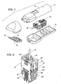
FIG. 1 is an exploded perspective view of a hair cutter utilizing a linear oscillating actuator system in accordance with a preferred embodiment of the present invention; -
FIG. 2 is a perspective view of an actuator of the above system; -
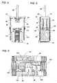
FIG. 3 is a front view of the actuator; -
FIG. 4 is a side view of the actuator; -
FIG. 5 is a top view of the actuator shown with a portion thereof removed; -
FIG. 6 is an exploded perspective view of the actuator system shown with a portion removed; -
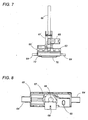
FIG. 7 is a front view of an oscillator employed in the actuator system; and -
FIG. 8 is a top view of the oscillator; and -
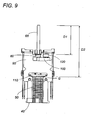
FIG. 9 is a front view of the actuator shown with a portion thereof cut away. - Now referring to
FIG. 1 , there is shown a hair cutter as one typical example which utilizes a linear oscillating actuator system of the present invention. The hair cutter includes ahousing 10 composed ofhalves actuator 30, and acutter block 20 composed of amovable cutter 21 and astationary cutter 22 fixed to thehousing 10. Theactuator 30 has anoutput shaft 66 which is connected to themovable cutter 21 for reciprocating it relative to thestationary cutter 22 for cutting hairs therebetween. - As best shown in
FIGS. 2 to 6 , theactuator 30 is basically composed of astator assembly 40 carrying anelectromagnet 50, and anoscillator 60 carrying apermanent magnet 70 as well as theoutput shaft 66. Theelectromagnet 50 includes anE-shaped stator 51 having acenter core 52 and a pair ofside cores 53. Acoil 54 is wound around thecenter core 52 to magnetize pole ends at the respective upper ends of the center and side cores to opposite polarity upon being energized by a current. Thestator assembly 40 includes a generallyU-shaped frame 90 secured to and project on the upper end of theelectromagnet 50 for suspending theoscillator 60 as well as abalancer 100 in a closely adjacent relation to the upper end of theelectromagnet 50 by means ofhangers 80. Each ofhangers 80 include aheader 81 fixed to the upper end of theframe 90 and threespring links header 81 for connection at their lower ends respectively with theoscillator 60 and thebalancer 100. - The
oscillator 60 is molded from a plastic material into a horizontallyelongated base 62 withstuds 64 on its opposite ends for welded connection intoholes 84 at the lower ends of the associatedspring links 82. Thepermanent magnet 70 is exposed on the bottom of thebase 62 and is backed-up by amagnetic yoke 72 secured to the lower end of the base 61. Theoutput shaft 66 projects upwardly from a center of thebase 62 with respect to the length and width thereof. Theoutput shaft 66 is made of a metal and extends through thebase 62 with its lower end anchored to themagnetic yoke 72, as best shown inFIG. 7 . Likewise, thebalancer 100 is molded from a plastic material and shaped into a generally U-shaped configuration withparallel crosspieces 102 between which theoscillator 60 is positioned. Each of thecrosspieces 102 is formed at its opposite ends withstuds 105 for welded connection respectively intoholes 85 at the lower ends of the associatedspring links 83. Apermanent magnet 110 is exposed on the bottom of eachcrosspiece 102 and is backed-up by amagnetic yoke 112 secured to the lower end of eachcrosspiece 102. - Upon being supplied with an alternating current, the
electromagnet 50 generates an alternating magnetic field which interacts with thepermanent magnets oscillator 60 as well as thebalancer 100 respectively in linear paths. Thepermanent magnets oscillator 60 and thebalancer 100 are driven in a counter reciprocating manner, i.e., in a reveres phase relation with each other. - The
balancer 100 is configured to have a mass which is generally equal to that of theoscillator 60 inclusive of theoutput shaft 66, and to be devoid of any output member driving an external member, thereby canceling out the stator vibrations which would otherwise develop on the side of thestator assembly 40 to lower the output efficiency as well as be felt by the user grasping thehousing 10. In this connection, since theoutput shaft 66 projects from the center of theoscillator 60 particularly with respect to the horizontal thickness thereof, theoscillator 60 can be free from receiving a rotation movement about theoutput shaft 66 while driving the load, thereby minimizing a torsion being applied to the spring links 82 or the mounting member for supporting theoscillator 60 to thestator assembly 40. Also, thebalancer 100 is configured to align its mass center with that of theoscillator 60 around theoutput shaft 66 in order to keep theoscillator 60 free from undesired lateral vibrations. Thebase 62 of theoscillator 60 is formed with acollar 67 which surrounds the lower end of theoutput shaft 66 and is shaped to receive a weight for adjusting the mass of theoscillator 60 in match with thebalancer 100. Further, thebase 62 is also formed with aslit 68 for mounting a marker (not shown) by which the position of theoscillator 60 is monitored for feedback control of its movement. - In order to assist the reverse phase relation between the
oscillator 60 and thebalancer 100, they are interconnected by amechanical link 120 at a level upwardly of thepermanent magnet 70 along the height of theoutput shaft 66, as shown inFIGS. 6 and9 . Themechanical link 120 is formed in its top with an axle 121 rotatably supported to the upper end of theframe 90, and is also formed on its bottom with twopins bore 65 in the upper end of the base 62 at a portion offset from theoutput shaft 66 and the other of which fits into abore 106 in the upper end of thecrosspiece 102. - As shown in
FIG. 9 , themechanical link 120 interconnects theoscillator 60 to thebalancer 100 sufficiently upwardly of the gap G between the permanent magnets and theelectromagnet 50 where theoscillator 60 receives a thrust from the electromagnet. Thus, the distance D1 between the top end of theoutput shaft 66 is made considerably shorter than distance D2 between the top end of theoutput shaft 66 to the gap, which gives sufficient resistance against the bending of theoutput shaft 66 when driving to reciprocate the load connected to the top end of the output shaft. - Further, the
oscillator 60 and thebalancer 100 are interconnected by a plurality of coupler springs 140 also for assisting the reverse phase relation. The coupler springs 140 are configured to resiliently deform, in response to thebalancer 100 moving in one direction, so as to add a resulting bias to theoscillator 60 moving in the opposite direction for driving the load at an optimum output efficiency. The two coupler springs 140 are positioned on each longitudinal end of theoscillator 60 for interconnecting theoscillator 60 to the onecrosspiece 102 of thebalancer 100. The interconnection is made simultaneously at the connection of the spring links 82 and 83 to theoscillator 60 and thebalancer 100. For this purpose, eachcoupler spring 140 is formed at its upper end withmount holes studs oscillator 60 and thebalancer 100. Eachcoupler spring 140 includes aspring leg 142 which is bent in a vertical plane and is disposed in an overlapping relation to each opposite side of thestator assembly 40.
Claims (6)
- A linear oscillating actuator system comprising:a housing (10);an oscillator (60) carrying a permanent magnet (70) as well as an output shaft (66) which is adapted to be connected to drive a load; and,a stator assembly (40) incorporated in said housing (10), said stator assembly (40) configured to movably support said oscillator (60) and to carry an electromagnet (50),said electromagnet (50) generating a magnetic field which interacts with said permanent magnet (70) to reciprocate said oscillator (60) relative to said stator assembly (40) in a linear path,whereina balancer (100) is supported to said stator assembly (40), said balancer (100) including a permanent magnet (110) which interacts with said magnetic field for reciprocating said balancer (100) along said linear path in an opposite phase relation with said oscillator (60),said balancer (100) being configured to have a mass generally equal to that of said oscillator (60) and to be devoid of any output member,wherein said stator assembly (40) includes mounting members (80) for supporting said oscillator (60) and said balancer (100); and characterized in that said oscillator (60) and said balancer (100) are interconnected by way of coupler springs (140),said mounting member (80) and said coupler springs (140) are secured to said oscillator (60) at the same spots (64); andsaid mounting member (80) and said coupler springs (140) are secured to said balancer (100) at the same spots (105).
- The linear oscillating actuator system as set forth in claim 1, wherein
said oscillator (60) has a thickness perpendicular to said linear path, and said output shaft (66) projects from a center of the thickness of said oscillator (60). - The linear oscillating actuator system as set forth in claim 1, wherein
said oscillator (60) and said balancer (100) have their respective mass centers aligned around said output shaft (66). - The linear oscillating actuator system as set forth in claim 1, wherein
said oscillator (60) is shaped from a plastic mold into which a magnetic yoke (72) is entrapped in contact with said permanent magnet (70), said output shaft (66) being secured to said magnetic yoke (72). - The linear oscillating actuator system as set forth in claim 1, wherein
said oscillator (60) and said balancer (100) are interconnected by a mechanical link (120) for assisting said reverse phase relation therebetween,
said mechanical link (120) being connected to said oscillator (60) at a point spaced upwardly of said permanent magnet (70) along a length of said output shaft (66). - A hair cutter incorporating the linear oscillating actuator system as set forth in any of the preceding claims, wherein
said hair cutter includes a movable cutter (21) movable relative to a stationary cutter (22),
said movable cutter (21) being connected to said output shaft (66) to be driven thereby to reciprocate for cutting hair.
Applications Claiming Priority (2)
| Application Number | Priority Date | Filing Date | Title |
|---|---|---|---|
| JP2003425860 | 2003-12-22 | ||
| JP2003425860A JP2005185067A (en) | 2003-12-22 | 2003-12-22 | Vibration-type linear actuator and hair cutter provided with the same |
Publications (3)
| Publication Number | Publication Date |
|---|---|
| EP1548918A2 EP1548918A2 (en) | 2005-06-29 |
| EP1548918A3 EP1548918A3 (en) | 2007-12-26 |
| EP1548918B1 true EP1548918B1 (en) | 2012-08-01 |
Family
ID=34544955
Family Applications (1)
| Application Number | Title | Priority Date | Filing Date |
|---|---|---|---|
| EP04029572A Active EP1548918B1 (en) | 2003-12-22 | 2004-12-14 | Linear oscillating actuator system |
Country Status (5)
| Country | Link |
|---|---|
| US (1) | US7053507B2 (en) |
| EP (1) | EP1548918B1 (en) |
| JP (1) | JP2005185067A (en) |
| KR (1) | KR100667961B1 (en) |
| CN (2) | CN2764042Y (en) |
Families Citing this family (23)
| Publication number | Priority date | Publication date | Assignee | Title |
|---|---|---|---|---|
| JP4400463B2 (en) * | 2005-01-19 | 2010-01-20 | パナソニック電工株式会社 | Vibration type linear actuator and electric toothbrush using the same |
| JP5174808B2 (en) * | 2006-05-01 | 2013-04-03 | コーニンクレッカ フィリップス エレクトロニクス エヌ ヴィ | Cutting device and hair cutting instrument |
| JP4497227B2 (en) * | 2008-04-24 | 2010-07-07 | パナソニック電工株式会社 | Vibration type linear actuator |
| KR101156780B1 (en) * | 2009-07-22 | 2012-06-18 | 삼성전기주식회사 | Horizontal Linear vibrator |
| US9553497B2 (en) | 2009-07-22 | 2017-01-24 | Mplus Co., Ltd. | Horizontal linear vibrator |
| KR101070377B1 (en) * | 2009-09-29 | 2011-10-06 | 삼성전기주식회사 | vibration motor |
| CN102684445B (en) * | 2011-03-07 | 2016-08-10 | 德昌电机(深圳)有限公司 | Electric shearing tool and driver thereof |
| JP5945814B2 (en) * | 2011-12-05 | 2016-07-05 | パナソニックIpマネジメント株式会社 | Linear actuator and oral hygiene device including the same |
| JP5995083B2 (en) * | 2012-12-27 | 2016-09-21 | パナソニックIpマネジメント株式会社 | Electric linear actuator and output shaft vibration type electric apparatus having the electric linear actuator |
| JP6152968B2 (en) * | 2012-12-27 | 2017-06-28 | パナソニックIpマネジメント株式会社 | Electric linear actuator and output shaft vibration type electric apparatus having the electric linear actuator |
| US10821617B2 (en) * | 2016-01-14 | 2020-11-03 | Nathan Hitson | Animal shears/clippers |
| EP3300848B1 (en) * | 2016-09-28 | 2019-10-23 | Braun GmbH | Electric shaver |
| KR101875817B1 (en) * | 2016-10-06 | 2018-07-06 | 박보현 | Vibratory linear actuator system clippers |
| JP6715465B2 (en) | 2017-04-19 | 2020-07-01 | パナソニックIpマネジメント株式会社 | Vibration type linear actuator, hair treatment machine and method of manufacturing vibration type linear actuator |
| JP6793367B2 (en) | 2017-04-19 | 2020-12-02 | パナソニックIpマネジメント株式会社 | Vibration type linear actuator and cutting device |
| JP6765079B2 (en) | 2017-04-19 | 2020-10-07 | パナソニックIpマネジメント株式会社 | Vibration type linear actuator and hair treatment machine |
| JP6793366B2 (en) * | 2017-04-19 | 2020-12-02 | パナソニックIpマネジメント株式会社 | Vibration type linear actuator and cutting device |
| EP3396828B1 (en) * | 2017-04-27 | 2021-08-18 | Braun GmbH | Electric appliance for personal care |
| EP3396827B1 (en) * | 2017-04-27 | 2023-06-28 | Braun GmbH | Electric appliance for personal care |
| EP3396826B1 (en) | 2017-04-27 | 2022-10-19 | Braun GmbH | Electric appliance for personal care |
| EP3396821B1 (en) | 2017-04-27 | 2023-06-14 | Braun GmbH | Electric shaver |
| CN108258874B (en) * | 2017-12-27 | 2019-11-01 | 广州赤力科技有限公司 | Rotary actuator and electric device |
| JPWO2022185818A1 (en) * | 2021-03-02 | 2022-09-09 |
Family Cites Families (7)
| Publication number | Priority date | Publication date | Assignee | Title |
|---|---|---|---|---|
| NL264048A (en) | 1960-09-29 | |||
| JPS5342235B2 (en) | 1972-11-29 | 1978-11-09 | ||
| US5678312A (en) | 1994-10-31 | 1997-10-21 | Sanyo Electric Co., Ltd. | Electric shaver with reduced vibration |
| JP3266757B2 (en) * | 1995-05-26 | 2002-03-18 | 松下電工株式会社 | Vibration type linear actuator |
| JP3736282B2 (en) | 2000-04-25 | 2006-01-18 | 松下電工株式会社 | Vibration type linear actuator |
| EP1162721B1 (en) | 2000-06-07 | 2005-12-21 | Matsushita Electric Works, Ltd. | Linear oscillating actuator |
| JP3736296B2 (en) | 2000-06-07 | 2006-01-18 | 松下電工株式会社 | Vibration type linear actuator |
-
2003
- 2003-12-22 JP JP2003425860A patent/JP2005185067A/en active Pending
-
2004
- 2004-12-14 EP EP04029572A patent/EP1548918B1/en active Active
- 2004-12-17 US US11/013,331 patent/US7053507B2/en active Active
- 2004-12-22 CN CNU2004201210460U patent/CN2764042Y/en not_active Expired - Fee Related
- 2004-12-22 CN CNB2004100820242A patent/CN100392951C/en active Active
- 2004-12-22 KR KR1020040110309A patent/KR100667961B1/en active IP Right Grant
Also Published As
| Publication number | Publication date |
|---|---|
| CN1638237A (en) | 2005-07-13 |
| US20050134123A1 (en) | 2005-06-23 |
| EP1548918A3 (en) | 2007-12-26 |
| CN2764042Y (en) | 2006-03-08 |
| CN100392951C (en) | 2008-06-04 |
| US7053507B2 (en) | 2006-05-30 |
| EP1548918A2 (en) | 2005-06-29 |
| KR20050063734A (en) | 2005-06-28 |
| KR100667961B1 (en) | 2007-01-11 |
| JP2005185067A (en) | 2005-07-07 |
Similar Documents
| Publication | Publication Date | Title |
|---|---|---|
| EP1548918B1 (en) | Linear oscillating actuator system | |
| US8680723B2 (en) | Linear actuator | |
| EP1332843B1 (en) | Electric hair clipper | |
| US7015602B2 (en) | Small electric appliance with a drive mechanism for generating an oscillatory motion | |
| US5444313A (en) | Electromagnetic actuator having two opposite phase movable parts | |
| EP1548917B1 (en) | Linear oscillating actuator | |
| EP3252935A1 (en) | Implement for personal cleaning and care | |
| US7504751B2 (en) | Small electric appliance with a drive mechanism for generating an oscillatory motion | |
| EP2112754B1 (en) | Vibratory linear actuator | |
| JP2004023909A (en) | Vibration-type linear actuator | |
| EP1091477B1 (en) | Vibration generator | |
| US20070113409A1 (en) | Electric shaving apparatus with a pivotal shaving head | |
| KR100881796B1 (en) | Hair clipper | |
| JP5260927B2 (en) | Vibration type linear actuator | |
| JP3915607B2 (en) | Vibrating linear actuator and electric shaver using the same | |
| JP3841021B2 (en) | Vibration type linear actuator | |
| JP3736282B2 (en) | Vibration type linear actuator | |
| JP2005537897A (en) | Drive mechanism for generating oscillating motion in small appliances | |
| JP2002177665A (en) | Reciprocating electric razor | |
| JPH11285226A (en) | Oscillation type linear actuator | |
| CN219960373U (en) | Linear motor device | |
| JP3433571B2 (en) | Reciprocating electric razor | |
| JP3382062B2 (en) | Linear vibration motor | |
| JP3884569B2 (en) | Vibration type linear actuator | |
| JP3382057B2 (en) | Linear actuator |
Legal Events
| Date | Code | Title | Description |
|---|---|---|---|
| PUAI | Public reference made under article 153(3) epc to a published international application that has entered the european phase |
Free format text: ORIGINAL CODE: 0009012 |
|
| AK | Designated contracting states |
Kind code of ref document: A2 Designated state(s): AT BE BG CH CY CZ DE DK EE ES FI FR GB GR HU IE IS IT LI LT LU MC NL PL PT RO SE SI SK TR |
|
| AX | Request for extension of the european patent |
Extension state: AL BA HR LV MK YU |
|
| PUAL | Search report despatched |
Free format text: ORIGINAL CODE: 0009013 |
|
| AK | Designated contracting states |
Kind code of ref document: A3 Designated state(s): AT BE BG CH CY CZ DE DK EE ES FI FR GB GR HU IE IS IT LI LT LU MC NL PL PT RO SE SI SK TR |
|
| AX | Request for extension of the european patent |
Extension state: AL BA HR LV MK YU |
|
| 17P | Request for examination filed |
Effective date: 20080617 |
|
| AKX | Designation fees paid |
Designated state(s): AT BE BG CH CY CZ DE DK EE ES FI FR GB GR HU IE IS IT LI LT LU MC NL PL PT RO SE SI SK TR |
|
| RAP1 | Party data changed (applicant data changed or rights of an application transferred) |
Owner name: PANASONIC ELECTRIC WORKS CO., LTD. |
|
| 17Q | First examination report despatched |
Effective date: 20091030 |
|
| REG | Reference to a national code |
Ref country code: DE Ref legal event code: R079 Ref document number: 602004038705 Country of ref document: DE Free format text: PREVIOUS MAIN CLASS: H02K0033160000 Ipc: B26B0019280000 |
|
| RIC1 | Information provided on ipc code assigned before grant |
Ipc: H02K 33/16 20060101ALI20111117BHEP Ipc: B26B 19/28 20060101AFI20111117BHEP Ipc: H02K 33/06 20060101ALI20111117BHEP |
|
| GRAP | Despatch of communication of intention to grant a patent |
Free format text: ORIGINAL CODE: EPIDOSNIGR1 |
|
| RAP1 | Party data changed (applicant data changed or rights of an application transferred) |
Owner name: PANASONIC CORPORATION |
|
| GRAS | Grant fee paid |
Free format text: ORIGINAL CODE: EPIDOSNIGR3 |
|
| GRAA | (expected) grant |
Free format text: ORIGINAL CODE: 0009210 |
|
| AK | Designated contracting states |
Kind code of ref document: B1 Designated state(s): AT BE BG CH CY CZ DE DK EE ES FI FR GB GR HU IE IS IT LI LT LU MC NL PL PT RO SE SI SK TR |
|
| REG | Reference to a national code |
Ref country code: GB Ref legal event code: FG4D |
|
| REG | Reference to a national code |
Ref country code: CH Ref legal event code: EP Ref country code: AT Ref legal event code: REF Ref document number: 568414 Country of ref document: AT Kind code of ref document: T Effective date: 20120815 |
|
| REG | Reference to a national code |
Ref country code: IE Ref legal event code: FG4D |
|
| RIN2 | Information on inventor provided after grant (corrected) |
Inventor name: MOTOHASHI, RYO Inventor name: NISHINAKA, TAKAHIRO Inventor name: YABUUCHI, HIDEKAZU Inventor name: KOBAYASHI, NOBORU Inventor name: MORIGUCHI, MASASHI |
|
| REG | Reference to a national code |
Ref country code: DE Ref legal event code: R096 Ref document number: 602004038705 Country of ref document: DE Effective date: 20120927 |
|
| REG | Reference to a national code |
Ref country code: NL Ref legal event code: VDEP Effective date: 20120801 |
|
| REG | Reference to a national code |
Ref country code: AT Ref legal event code: MK05 Ref document number: 568414 Country of ref document: AT Kind code of ref document: T Effective date: 20120801 |
|
| RIN2 | Information on inventor provided after grant (corrected) |
Inventor name: MORIGUCHI, MASASHI Inventor name: YABUUCHI, HIDEKAZU Inventor name: MOTOHASHI, RYO Inventor name: NISHINAKA, TAKAHIRO Inventor name: KOBAYASHI, NOBORU |
|
| RIN2 | Information on inventor provided after grant (corrected) |
Inventor name: MOTOHASHI, RYO Inventor name: NISHINAKA, TAKAHIRO Inventor name: KOBAYASHI, NOBORU Inventor name: YABUUCHI, HIDEKAZU Inventor name: MORIGUCHI, MASASHI |
|
| REG | Reference to a national code |
Ref country code: LT Ref legal event code: MG4D Effective date: 20120801 |
|
| PG25 | Lapsed in a contracting state [announced via postgrant information from national office to epo] |
Ref country code: CY Free format text: LAPSE BECAUSE OF FAILURE TO SUBMIT A TRANSLATION OF THE DESCRIPTION OR TO PAY THE FEE WITHIN THE PRESCRIBED TIME-LIMIT Effective date: 20120801 Ref country code: LT Free format text: LAPSE BECAUSE OF FAILURE TO SUBMIT A TRANSLATION OF THE DESCRIPTION OR TO PAY THE FEE WITHIN THE PRESCRIBED TIME-LIMIT Effective date: 20120801 Ref country code: AT Free format text: LAPSE BECAUSE OF FAILURE TO SUBMIT A TRANSLATION OF THE DESCRIPTION OR TO PAY THE FEE WITHIN THE PRESCRIBED TIME-LIMIT Effective date: 20120801 Ref country code: IS Free format text: LAPSE BECAUSE OF FAILURE TO SUBMIT A TRANSLATION OF THE DESCRIPTION OR TO PAY THE FEE WITHIN THE PRESCRIBED TIME-LIMIT Effective date: 20121201 Ref country code: FI Free format text: LAPSE BECAUSE OF FAILURE TO SUBMIT A TRANSLATION OF THE DESCRIPTION OR TO PAY THE FEE WITHIN THE PRESCRIBED TIME-LIMIT Effective date: 20120801 |
|
| PG25 | Lapsed in a contracting state [announced via postgrant information from national office to epo] |
Ref country code: PT Free format text: LAPSE BECAUSE OF FAILURE TO SUBMIT A TRANSLATION OF THE DESCRIPTION OR TO PAY THE FEE WITHIN THE PRESCRIBED TIME-LIMIT Effective date: 20121203 Ref country code: SI Free format text: LAPSE BECAUSE OF FAILURE TO SUBMIT A TRANSLATION OF THE DESCRIPTION OR TO PAY THE FEE WITHIN THE PRESCRIBED TIME-LIMIT Effective date: 20120801 Ref country code: BE Free format text: LAPSE BECAUSE OF FAILURE TO SUBMIT A TRANSLATION OF THE DESCRIPTION OR TO PAY THE FEE WITHIN THE PRESCRIBED TIME-LIMIT Effective date: 20120801 Ref country code: GR Free format text: LAPSE BECAUSE OF FAILURE TO SUBMIT A TRANSLATION OF THE DESCRIPTION OR TO PAY THE FEE WITHIN THE PRESCRIBED TIME-LIMIT Effective date: 20121102 Ref country code: PL Free format text: LAPSE BECAUSE OF FAILURE TO SUBMIT A TRANSLATION OF THE DESCRIPTION OR TO PAY THE FEE WITHIN THE PRESCRIBED TIME-LIMIT Effective date: 20120801 Ref country code: SE Free format text: LAPSE BECAUSE OF FAILURE TO SUBMIT A TRANSLATION OF THE DESCRIPTION OR TO PAY THE FEE WITHIN THE PRESCRIBED TIME-LIMIT Effective date: 20120801 |
|
| PG25 | Lapsed in a contracting state [announced via postgrant information from national office to epo] |
Ref country code: NL Free format text: LAPSE BECAUSE OF FAILURE TO SUBMIT A TRANSLATION OF THE DESCRIPTION OR TO PAY THE FEE WITHIN THE PRESCRIBED TIME-LIMIT Effective date: 20120801 |
|
| PG25 | Lapsed in a contracting state [announced via postgrant information from national office to epo] |
Ref country code: ES Free format text: LAPSE BECAUSE OF FAILURE TO SUBMIT A TRANSLATION OF THE DESCRIPTION OR TO PAY THE FEE WITHIN THE PRESCRIBED TIME-LIMIT Effective date: 20121112 Ref country code: DK Free format text: LAPSE BECAUSE OF FAILURE TO SUBMIT A TRANSLATION OF THE DESCRIPTION OR TO PAY THE FEE WITHIN THE PRESCRIBED TIME-LIMIT Effective date: 20120801 Ref country code: EE Free format text: LAPSE BECAUSE OF FAILURE TO SUBMIT A TRANSLATION OF THE DESCRIPTION OR TO PAY THE FEE WITHIN THE PRESCRIBED TIME-LIMIT Effective date: 20120801 Ref country code: CZ Free format text: LAPSE BECAUSE OF FAILURE TO SUBMIT A TRANSLATION OF THE DESCRIPTION OR TO PAY THE FEE WITHIN THE PRESCRIBED TIME-LIMIT Effective date: 20120801 Ref country code: RO Free format text: LAPSE BECAUSE OF FAILURE TO SUBMIT A TRANSLATION OF THE DESCRIPTION OR TO PAY THE FEE WITHIN THE PRESCRIBED TIME-LIMIT Effective date: 20120801 |
|
| PG25 | Lapsed in a contracting state [announced via postgrant information from national office to epo] |
Ref country code: SK Free format text: LAPSE BECAUSE OF FAILURE TO SUBMIT A TRANSLATION OF THE DESCRIPTION OR TO PAY THE FEE WITHIN THE PRESCRIBED TIME-LIMIT Effective date: 20120801 |
|
| PLBE | No opposition filed within time limit |
Free format text: ORIGINAL CODE: 0009261 |
|
| STAA | Information on the status of an ep patent application or granted ep patent |
Free format text: STATUS: NO OPPOSITION FILED WITHIN TIME LIMIT |
|
| 26N | No opposition filed |
Effective date: 20130503 |
|
| PG25 | Lapsed in a contracting state [announced via postgrant information from national office to epo] |
Ref country code: BG Free format text: LAPSE BECAUSE OF FAILURE TO SUBMIT A TRANSLATION OF THE DESCRIPTION OR TO PAY THE FEE WITHIN THE PRESCRIBED TIME-LIMIT Effective date: 20121101 Ref country code: MC Free format text: LAPSE BECAUSE OF NON-PAYMENT OF DUE FEES Effective date: 20121231 |
|
| REG | Reference to a national code |
Ref country code: CH Ref legal event code: PL |
|
| GBPC | Gb: european patent ceased through non-payment of renewal fee |
Effective date: 20121214 |
|
| REG | Reference to a national code |
Ref country code: DE Ref legal event code: R097 Ref document number: 602004038705 Country of ref document: DE Effective date: 20130503 |
|
| REG | Reference to a national code |
Ref country code: IE Ref legal event code: MM4A |
|
| PG25 | Lapsed in a contracting state [announced via postgrant information from national office to epo] |
Ref country code: IE Free format text: LAPSE BECAUSE OF NON-PAYMENT OF DUE FEES Effective date: 20121214 Ref country code: CH Free format text: LAPSE BECAUSE OF NON-PAYMENT OF DUE FEES Effective date: 20121231 Ref country code: LI Free format text: LAPSE BECAUSE OF NON-PAYMENT OF DUE FEES Effective date: 20121231 |
|
| PG25 | Lapsed in a contracting state [announced via postgrant information from national office to epo] |
Ref country code: GB Free format text: LAPSE BECAUSE OF NON-PAYMENT OF DUE FEES Effective date: 20121214 |
|
| PGFP | Annual fee paid to national office [announced via postgrant information from national office to epo] |
Ref country code: IT Payment date: 20131213 Year of fee payment: 10 |
|
| PG25 | Lapsed in a contracting state [announced via postgrant information from national office to epo] |
Ref country code: TR Free format text: LAPSE BECAUSE OF FAILURE TO SUBMIT A TRANSLATION OF THE DESCRIPTION OR TO PAY THE FEE WITHIN THE PRESCRIBED TIME-LIMIT Effective date: 20120801 |
|
| PG25 | Lapsed in a contracting state [announced via postgrant information from national office to epo] |
Ref country code: LU Free format text: LAPSE BECAUSE OF NON-PAYMENT OF DUE FEES Effective date: 20121214 |
|
| PGFP | Annual fee paid to national office [announced via postgrant information from national office to epo] |
Ref country code: FR Payment date: 20131220 Year of fee payment: 10 |
|
| PG25 | Lapsed in a contracting state [announced via postgrant information from national office to epo] |
Ref country code: HU Free format text: LAPSE BECAUSE OF FAILURE TO SUBMIT A TRANSLATION OF THE DESCRIPTION OR TO PAY THE FEE WITHIN THE PRESCRIBED TIME-LIMIT Effective date: 20041214 |
|
| REG | Reference to a national code |
Ref country code: FR Ref legal event code: ST Effective date: 20150831 |
|
| PG25 | Lapsed in a contracting state [announced via postgrant information from national office to epo] |
Ref country code: FR Free format text: LAPSE BECAUSE OF NON-PAYMENT OF DUE FEES Effective date: 20141231 |
|
| PG25 | Lapsed in a contracting state [announced via postgrant information from national office to epo] |
Ref country code: IT Free format text: LAPSE BECAUSE OF NON-PAYMENT OF DUE FEES Effective date: 20141214 |
|
| PGFP | Annual fee paid to national office [announced via postgrant information from national office to epo] |
Ref country code: DE Payment date: 20231214 Year of fee payment: 20 |