TECHNICAL FIELD
-
The present invention relates to a precision processing
stage apparatus and, more specifically, to a precision
processing stage apparatus used in precision processing, wiring
works, or inspections performed afterwards, etc. during a
process of manufacturing semiconductors such as IC and LSI.
BACKGROUND ART
-
Conventionally, in the semiconductor industry and the
like, generally used is a processing stage apparatus which
comprises a movable table capable of precise movement in order
to set and hold a workpiece in a position for precision
processing or for an inspection, etc. in a manufacturing process
of IC, LSI and the like.
-
In this case, in order to precisely move the movable table
to an arbitrary position on an X-Y plane, generally used is a
type of apparatus comprising a moving-body holding mechanism
in a double structure, in which, first, the entire movable table
is moved by an X-direction moving mechanism in the X direction
and subsequently (or simultaneously) the entire movable table
and the X-direction moving mechanism are moved by a Y-direction
moving mechanism in the Y direction.
-
Further, most of the processing stage apparatus of this
kind comprises a mechanical braking mechanism which drives at
a relatively slow speed for controlling the movement of the
movable table in the X direction and Y direction.
-
However, the conventional stage apparatus comprises: the
moving-body holding mechanism in a double structure in which,
as described above, the X-direction moving mechanism for
movements in the X direction and the Y-direction moving
mechanism for movements in the Y direction intersect with each
other; and the in-contact moving section which especially
requires the precision has a running-in structure. Therefore,
it is time-consuming to perform processing and also requires
a skill to perform precise adjustment at the time of assembling,
thereby causing inconvenience. Thus, the productivity is
deteriorated so that the price of the whole apparatus is
increased in many cases.
-
Furthermore, for automating the system in connection with
moving the table, it requires a large space for connecting the
double-structures driving mechanism and mounting a positioning
sensor and the like. Thus, the whole apparatus becomes
large-scaled.
-
Moreover, in most of the conventional stage apparatuses,
a return spring for returning to the original position is
provided to the movable table. In this case, a slight
reciprocal movement is likely to be generated in the movable
table at a stop position due to the acceleration or deceleration
of the driving force applied to the movable table at the time
of stopping the movable table. Thus, a mechanical braking
device utilizing friction is essential for making a stop at a
prescribed position.
-
In the meantime, this type of mechanical friction braking
is likely to generate small oscillation at the time of operation,
so that the movement when making a stop becomes unstable when
performing precision movement by micron unit. Also, the whole
apparatus becomes large-scaled since the mechanical braking
mechanism is provided, so that there always faces the
shortcomings that the portability is bad and the maintenance
characteristic is also deteriorated.
-
An object of the present invention is to provide a
precision processing stage apparatus comprising a function of
smoothly carrying out a precise moving of a precision processing
movable table on the same plane in prescribed directions, which
is capable of a dramatic improvement in assembling work,
reduction of the size and weight of the whole apparatus and,
further, of suppressing the reciprocal movement and small
oscillation or the like at the time of stopping the movable table,
thereby achieving fast and smooth precision movement of the
movable table.
DISCLOSURE OF THE INVENTION
-
In order to achieve the foregoing objects, a precise
processing stage apparatus according to the present invention
comprises:
- a movable table installed in a main body part for
supporting a work piece;
- a table holding mechanism installed in the main body part
for allowing a movement of the movable table in arbitrary
directions within a same plane;
- an electromagnetic driving means installed in the main
body part for supplying a feed to the movable table within the
same plane; and
- an electromagnetic braking mechanism for generating a
braking force to stop the movable table at an arbitrary position
on the same plane, wherein:
- the electromagnetic driving means comprises: as a pair,
a plurality of driven magnets and a driving coil for generating
a magnetic force working on a magnetic force of the driven
magnets according to an energizing direction so as to supply
a feed to the movable table through a mutual magnetic effect
between the driven magnets and the driving coil;
- either the driven magnet or the driving coil is fixed at
a prescribed position while the other is disposed to be
integrally movable with the movable table;
- the electromagnetic braking mechanism includes braking
magnets which face with each other and relatively move by
synchronizing with the movement of the movable table and a
nonmagnetic/conductive braking plate; and
- either the braking magnets or the braking plate is fixed
at a prescribed position and the other is disposed to be movable
by synchronizing with the movement of the movable table, and
a pair of the braking magnets and the braking plate is for
generating a braking force based on a mutual magnetic effect
between a magnetic force by an eddy current generated in the
braking plate in accordance with the movement of the movable
table and a magnetic force of the braking magnets.
-
-
In the present invention, when the electromagnetic
driving means is started, first, a mutual magnetic effect is
generated between the driving coils and the driven magnets of
the electromagnetic driving means and a feed in a prescribed
direction is supplied to the movable table by the mutual
magnetic effect. In this case, the movable table is allowed
to move within the same plane by the table holding mechanism
so that it can be smoothly moved in a prescribed direction
without a vertical movement. Especially, when an original
position returning force is given to the movable table, it is
moved to a position (that is, a prescribed moving stop position)
in balance between the original position returning force and
the magnetic force of the electromagnetic driving means.
-
The movable table, when being moved, is suddenly
accelerated in many cases by the electromagnetic driving means
or the original position returning force applied to the movable
table. When the moving range of the movable table is in micron
unit, it is suddenly decelerated to be stopped while being
suddenly accelerated. Therefore, when the movable table is
stopped, it is likely to generate a slight reciprocal action
at the time of stopping the movable table due to inertia of the
movable table and the original position returning force of the
table holding mechanism.
-
In the present invention, when the movable table makes
a sudden movement, the braking magnets and the non-magnetic and
conductive braking plate of the electromagnetic braking
mechanism are relatively displaced by synchronizing with the
movement of the movable table. As for the electromagnetic
braking mechanism, an eddy current in a magnitude proportional
to the moving speed of the movable table is generated in the
braking plate so that the braking force is generated based on
the mutual magnetic effect between the magnetic force by the
eddy current generated in the braking plate and the magnetic
force of the braking magnets. By receiving the braking force
of the electromagnetic braking mechanism, the slight reciprocal
action of the movable table is converged within a short time.
-
Therefore, the stopping time required for stopping the
movable table at a desired position is shortened. Moreover,
the overall time required for moving the movable table within
the same plane is shortened so that the working efficiency can
be improved.
-
In the embodiment, the electromagnetic braking mechanism
may apply braking to the movable table or to the movable table
and the table holding mechanism.
-
Therefore, by applying the braking force of the
electromagnetic braking mechanism to the movable table, it is
possible to shorten the braking time of the movable table as
described above. Further, by applying the braking force of the
electromagnetic braking mechanism to both the movable table and
the table holding mechanism, it is possible to further shorten
the braking time of the movable table.
-
Further, in the present invention, the electromagnetic
braking mechanism has a simple configuration, comprising
braking magnets which face with each other and relatively move
by synchronizing with the movement of the movable table, and
the non-magnetic and conductive braking plate.
-
Accordingly, the size and weight of the entire apparatus
can be reduced. Therefore, inertia of the movable table is not
increased and the movement of the movable table is not to be
interfered. Also, special skills are not required for the
assembling work, so that the workability becomes excellent. In
this respect, the productivity can be largely improved compared
to the conventional case comprising the double-structured
moving mechanism.
-
Further, as for the braking magnets of the
electromagnetic braking mechanism, it is possible to use the
driven magnets forming the electromagnetic driving means or to
form separately from the driven magnets.
-
Therefore, in the case where the braking magnets of the
electromagnetic braking mechanism are formed with the driven
magnets, the braking plate forms a circuit equivalent to a
secondary circuit of transformer, since the part formed with
the driving coils of the electromagnetic driving means linking
a magnetic flux functions similarly with respect to the coils.
At the same time, the secondary circuit constitutes a form being
short-circuit at all times through an electric resistance
component (generates eddy current loss) of the braking plate.
-
As a result, an eddy current is flown to the braking plate
forming the secondary circuit in this case for canceling the
magnetic flux generated by the driving coils, so that there is
only the magnetic flux of the original driving magnets. Thus,
the driving force can be generated without distortion. Further,
the braking plate exhibits the same effect as that of a short
ring of a voice coil motor. Thus, impedance of a primary circuit
from the electric power point of view is small and it is possible
to energize a relatively large magnitude of current without
phase delay compared to the case where the secondary circuit
is in the open state (the case without the braking plate) . As
a result, it is possible to output a relatively large magnitude
of the electromagnetic force between with the driven magnets
without phase delay compared to the case without the braking
plate.
-
Moreover, the braking plate also functions as a radiator
plate. In this respect, the flown current can be set in a
constant level for a long time by effectively suppressing an
increase in the resistance under high temperatures and decrease
in the flown current value (that is, deterioration of the
electromagnetic driving force) caused in accordance with the
continuous operation of the driving coils. Thus, it enables
to continue, in the stable state, the current control from
outside for the driving force by the magnetic force outputted
from the electromagnetic driving means, so that change by aging
(dielectric breakdown by heat) can be suppressed. Therefore,
the durability of the entire apparatus and, moreover, the
reliability of the entire apparatus can be improved.
-
Further, it is desirable to mount the electromagnetic
braking mechanism in the center of the movable table. With this,
the braking force by the electromagnetic braking mechanism can
be uniformly and non-eccentrically applied to the movable table
so that the reciprocal action at the time of stopping the movable
table can be suppressed to a short time.
-
Further, the braking plate of the electromagnetic braking
mechanism may be formed as a single plate for a plurality of
the braking magnets. Thereby, it is possible to shorten the
time required for mounting the braking plate, and the efficiency
of the assembling work can be improved.
-
Furthermore, the movable table may be held by the table
holding mechanism directly or through an auxiliary table which
is connected in parallel and integrally with the movable table.
-
As described above, the manner of holding the movable
table by the table holding mechanism can be selected
appropriately, and it can be installed in a condition which can
effectively utilize the braking force of the electromagnetic
braking mechanism using the movable table and the auxiliary
table.
-
Moreover, as for the table holding mechanism, it is
possible to employ a condition, comprising: at least one set
of three rod-type elastic members provided in parallel on a same
circumferential of a peripheral edge of the movable table with
a prescribed space in between, whose one end being planted to
the movable table;
at least another set of three rod-type elastic members
in same length provided in parallel on a same circumferential
with a prescribed space in between on an outer side of the one
set of each rod-type elastic member by corresponding to the each
rod-type elastic member, whose one end being held by the main
body; and
an intermediate member for integrally holding other ends
of the one and the another sets of each rod-type elastic member
while maintaining the parallel state, wherein
each of the three pairs of rod-type elastic members of
the table holding mechanism is formed with a rod-type elastic
member such as a piano wire in same strength and same length.
-
As described, by forming the table holding mechanism as
a link mechanism, the movable table can be precisely moved when
being moved by a micron unit without moving the movable table
vertically on the same plane.
-
As described above, when the table holding mechanism is
formed as the link mechanism, it is desirable that one be
provided to be integrally movable with the movable table and
the other be provided to the main body part.
-
Further, as for the braking magnets or the braking plate
of the electromagnetic braking mechanism, one may be provided
to be integrally movable with the movable table and the other
may be provided to the main body part and, further, as for the
braking magnets or the braking plate of the electromagnetic
braking mechanism, one may be provided to be integrally movable
with the intermediate member and the other may be provided to
the main body part.
-
As described, by appropriately providing the
electromagnetic braking mechanism to the movable table and the
intermediate member of the table holding mechanism, the braking
force of the electromagnetic braking mechanism can be
effectively applied to the movable table.
-
Further, the braking magnets of the electromagnetic
braking mechanism can be formed with the driven magnets, or can
be formed separately from the driven magnets. Thereby, the set
position of the electromagnetic braking mechanism can be
appropriately selected so that the electromagnetic braking
mechanism can be set in a position where the braking force by
the electromagnetic braking mechanism can be effectively
utilized.
-
Further, the braking magnets of the electromagnetic
braking mechanism can be formed with either permanent magnets
or electromagnets. Thereby, the configuration of the driven
magnets of the electromagnetic driving means can be variously
modified. Moreover, by forming the driven magnets using the
electromagnets, the drive-control of the movable table can be
variously changed. For example, for
acceleration/deceleration at the time of moving the movable
table, the movable table can be moved by drive-controlling both
the driving coils and the electromagnets so that the moving
direction of the movable table can be promptly changed.
-
Furthermore, the table holding mechanism may comprise
an original position returning force for returning the movable
table to an original position. Thereby, the configuration of
the apparatus can be formed compact compared to the case where
the original position returning mechanism is provided
separately from the table holding mechanism.
-
Moreover, it is desirable that the driven magnets be
disposed, respectively, on a plurality of axes, which are
obtained by being equally divided in a circumferential
direction with a reference being a single axis passing through
an origin set within a plane where the movable table moves. In
this case, a plurality of the axes are set as a plurality of
axes which are orthogonal to each other, passing through the
origin set within the plane where the movable table moves, or
a plurality of the axes are set as a plurality of axes which
extend towards radial directions with the center being the
origin set within the plane where the movable table moves.
-
Furthermore, it is desirable that the original position
of the movable table returned by the table holding mechanism
may coincide with the origin which is the reference of the axes
set within the plane where the movable table moves.
-
Thereby, the returned position of the movable table by
the table holding mechanism coincides with the position as a
starting point for moving the movable table. Thus, the movable
table can be precisely positioned for being moved.
-
Further, it is desirable that a plurality of driven
magnets forming the electromagnetic driving means be disposed
on each axes at positions at equivalent distances from the
origin and a plurality of driving coils forming the
electromagnetic driving means be disposed by corresponding to
a plurality of the driven magnets.
-
Since the driven magnets and the driving coils forming
the electromagnetic driving means are disposed on the axes, it
enables to eliminate an excessive rotational force applied to
the movable table and an accurate positioning control of the
movable table can be achieved. By disposing a plurality of the
driven magnets on the axes at linear-symmetrical positions, it
is possible to surely eliminate a force which interferes with
the movement of the movable table.
-
It is desirable that the electromagnetic braking
mechanism be disposed on the axes. However, the pair of the
driven magnets and the driving coils may be disposed in
positions shifted from the axes. In the case where the set
positions of the pair of the driven magnets and the driving coils
are changed at will, it is also possible to stop the movable
table in a prescribed position using the braking force of the
electromagnetic braking mechanism. Thereby, it enables to
provide a stage apparatus with an extremely wide applicability.
-
Further, the driven magnets of the electromagnetic
driving means may be formed with permanent magnets or
electromagnets.
-
By forming the electromagnetic driving means using the
permanent magnets, an energizing circuit becomes unnecessary
unlike the case of using the electromagnets. For this, it
enables to avoid complication of work at the time of assembling
and maintenance inspection.
-
In the case where the driven magnets of the
electromagnetic driving means are formed with the
electromagnets, energization to the driven magnets is
selectively controlled either in a forward direction or reverse
direction by synchronizing with the energization to the driving
coils. Thereby, it is possible to apply various changes in the
drive-control of the movable table. Further, by individually
controlling the energization to a plurality of the driving coils,
extent of the feed supplied to the movable table by the
electromagnetic force can be modified at will.
-
Moreover, the driving coils comprise coil sides for
generating a magnetic force working on a magnetic force of the
driven magnets. In this case, it is desirable that the coil
side of the driving coil be formed in cross shape or linear shape,
or be positioned in a state to be along the axes where the driven
magnets are disposed. Thereby, the mutual magnetic effect can
be surely generated between the coil sides of the driving coil
and the driven magnets. Further, by selectively forming the
coil sides in cross shape or linear shape, the direction of the
mutual magnetic effect generated between with the driven
magnets can be arbitrarily selected. Thus, various changes can
be applied to the movement of the movable table.
-
Moreover, the driving coils can be formed with a plurality
of coils in different sizes being arranged on inner and outer
sides. Thereby, the mutual magnetic force generated between
the driving coils and the driven magnets can be doubled.
Therefore, the feeding force to the movable table can be
improved and the portability by the movable table can be
doubled.
-
In this case, it is desirable that the linear-shape coil
sides of the driving coil be disposed in a state to be along
or crossing with respect to the axes where the driven magnets
are disposed. Thereby, the mutual magnetic force generated
between the driving coils and the driven magnets can be
arbitrarily selected and the driving force for the movable table
can be variously modified.
-
Further, the driving coils can be formed by combining a
plurality of small coils which can be individually energized,
and the cross-shape or linear shape coil sides can be formed
in the area where the small coils abut with each other. Thereby,
the coil sides can be formed in the driving coils easily.
-
In this case, the small coils are formed in an angular
shape. Especially, it is desirable to be in a quadrangular,
triangular, pentagonal or fan shape. The angular shape of the
driving coil is so determined that the coil sides are easily
formed. Thus, it is not limited to the quadrangular, triangular,
pentagonal or fan shape.
-
Furthermore, it is desirable that an outer dimension of
the driving coil be set larger than that of the driven magnet.
Thereby, the electromagnetic driving force generated between
a plurality of the driving coils and the driven magnets can be
generated in the outward direction from the starting position
of the movable table at all times. Thus, the resultant force
of these electromagnetic driving forces can be also generated
in the outward direction from the starting position of the
movable table at all times.
-
Moreover, the electromagnetic driving means may comprise
an operation control system for linearly moving or linearly and
rotationally moving the movable table through controlling
energization to the driving coil. Thereby, it is possible to
apply changes in the movement of the movable table.
-
Further, it is possible to form the operation control
system, comprising: a coil driving control means for
energize-controlling the driving coils of the electromagnetic
driving means according to a control mode; a program storage
to which a plurality of control programs for a plurality of
control modes specifying the moving directions, rotation
directions, the amount of operation and the like of the movable
table are stored; a data storage to which prescribed coordinate
data and the like are stored to be used at the time of executing
each of the control programs; and an operation command input
section for giving a command to the coil driving control means
for performing a prescribed control operation on the driving
coils.
-
In this case, control codes of the operation control
system comprise: a first to a fourth control modes for moving
the movable table in positive and negative directions of each
axis with an intersection point of the two orthogonal axes being
an origin; a fifth to an eighth control modes for moving the
movable table in directions within each quadrant being
sectioned by the two orthogonal axes; and a ninth and a tenth
control modes for rotating the movable table in a clockwise
direction or counterclockwise direction within a plane formed
by the two orthogonal axes.
-
In the above-described configuration, the coil driving
control means is started according the a command from the
operation command input section and information of the moving
target position and a prescribed control mode for moving are
fetched from the program storage and the data storage. Based
on this, the driving coils of the electromagnetic driving means
are drive-controlled, thereby moving the movable table in a
prescribed direction.
-
Therefore, it is possible to drive-control the driving
coils based on the control mode for the driving coils stored
beforehand, so that it enables to promptly correspond to a
command from the operation command input section.
-
Further, as for the operation control system, in addition
to the above-described configuration, it is possible to employ
a configuration, comprising: a plurality of position detecting
sensors for detecting moving information of the movable table
to be outputted outside; and an positional information
arithmetic circuit for specifying the moving direction of the
movable table and amount of change and the like through
performing a prescribed arithmetic calculation based on
information detected by the position detecting sensors so as
to output it outside as positional information.
-
Therefore, moving information of the movable table and
the positional information after being moved can be outputted
outside in real-time, so that operators can easily obtain from
outside the moving direction of the movable table and the
position shift after being moved. Thus, it is possible to
highly precisely and promptly perform the moving work of the
movable table.
-
Further, as for the electromagnetic driving means, it may
employ a configuration, comprising an operation control system
which is started according to a command from outside for moving
the movable table in a prescribed moving direction through
individually controlling the driving coils and the driven
magnets of the electromagnetic driving means.
-
Thereby, it is possible to selectively activate one, two
or more of the driven magnets which effectively function towards
the moving direction of the movable table. Thus, it is possible
to surely move the movable table in a prescribed direction.
-
Moreover, it is possible that the operation control
system comprises: an energizing direction setting function for
setting and maintaining an energizing direction of the driving
coils in one direction; a driving coil energizing control
function for variably setting magnitude of the energizing
direction of the driving coils; a magnetic pole variably setting
function which operates according to the energizing direction
of the driving coils for individually setting and maintaining
the magnetic poles of the driven magnets; a magnetic force
magnitude setting function for individually and variably
setting the magnitude of the magnetic force of each driven
magnet according to a command from outside; and a table action
control function for adjusting the transporting direction and
transporting force for the movable table by appropriately
actuating the various functions.
-
Thereby, it is possible to specifically and surely move
the movable table in a prescribed direction.
BRIEF DESCRIPTION OF THE DRAWINGS
-
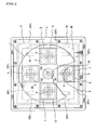
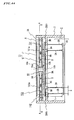
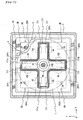
- FIG. 1 is a schematic cross section showing a first
embodiment of the present invention, in which a part is being
omitted;
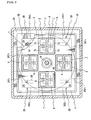
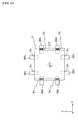
- FIG. 2 is a fragmentary sectional plan view of FIG. 1;
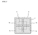
- FIG. 3 is a schematic cross section taken along a line
A-A of FIG. 1;
- FIG. 4 is a fragmentary sectional bottom view viewed from
the bottom side of FIG. 1;
- FIG. 5 is an explanatory illustration showing the
positional relation of the cross-in-square shape driving coil,
the driven magnets and the braking plate disclosed in FIG. 1;
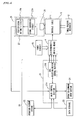
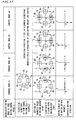
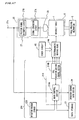
- FIG. 6 is a block diagram showing the relation of each
structural part shown in FIG. 1 and the operation control
system;
- FIGS. 7 are illustrations showing an operation example
of the auxiliary table (movable table) which is operated by the
operation control system disclosed in FIG. 6, in which FIG. 7 (A)
is an explanatory illustration showing the case where the
movable table is two-dimensionally moved in the upper right
direction at 45 °while FIG. (B) is an explanatory illustration
showing the case where the auxiliary table (movable table) is
rotated by an angle of ;
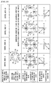
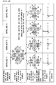
- FIG. 8 is a diagram showing four energizing patterns (the
energizing programs are stored in the program storage
beforehand) for energizing four small angular coils of the
driving coil disclosed in FIG. 1 to FIG. 4 and their functions;
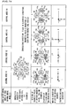
- FIGS. 9 are illustrations for showing the control mode
and the operating direction of the auxiliary table (movable
table) in the case were the operation control system disclosed
in FIG. 6 drive-controls the four driving coils, in which FIG.
9 (A) is an explanatory illustration showing a first control mode
and the operation of the auxiliary table (movable table) in the
X-axis (positive) direction while FIG. 9(B) is an explanatory
illustration for showing the relation between the magnitude of
the driving force and the point of action of this case;
- FIGS. 10 are illustrations for showing the control mode
and the operating direction of the auxiliary table (movable
table) in the case were the operation control system disclosed
in FIG. 6 drive-controls the four driving coils, in which FIG.
10(A) is an explanatory illustration showing a third control
mode and the operation of the auxiliary table (movable table)
in the Y-axis (positive) direction while FIG. 10(B) is an
explanatory illustration for showing the relation between the
magnitude of the driving force and the point of action of this
case;
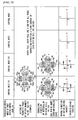
- FIGS. 11 are illustrations for showing the control mode
and the operating direction of the auxiliary table (movable
table) in the case were the operation control system disclosed
in FIG. 6 drive-controls the four driving coils, in which FIG.
11(A) is an explanatory illustration showing a fifth control
mode and the operation of the auxiliary table (movable table)
in the first quadrant direction on the X-Y coordinates while
FIG. 10(B) is an explanatory illustration for showing the
relation between the magnitude of the driving force and the
point of action of this case;
- FIGS. 12 are illustrations for showing the control mode
and the operating direction of the auxiliary table (movable
table) in the case where the operation control system disclosed
in FIG. 6 drive-controls the four driving coils, in which FIG.
12 (A) is an explanatory illustration showing a seventh control
mode and the operation of the auxiliary table (movable table)
in the second quadrant direction on the X-Y coordinates while
FIG. 12(B) is an explanatory illustration for showing the
relation between the magnitude of the driving force and the
point of action of this case;
- FIGS. 13 are illustrations for showing the control mode
and the operating direction of the auxiliary table (movable
table) in the case were the operation control system disclosed
in FIG. 6 drive-controls the four driving coils, in which FIG.
13(A) is an explanatory illustration showing a ninth control
mode and the rotation of the auxiliary table (movable table)
with the center being the origin on the X-Y coordinates while
FIG. 13(B) is an explanatory illustration for showing the
relation between the magnitude of the driving force and the
point of action of this case;
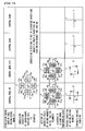
- FIGS. 14 are illustrations showing the positional
relation of the braking plate, the four driving coils and the
driven magnets disclosed in FIG. 1, in which FIG. 14(A) is a
fragmentary cross section showing the configuration including
the braking plate part while FIG. 14 (B) is a plan view viewed
along a line A-A of FIG. 14(A);
- FIGS. 15 are illustrations showing the principle of
generating the braking force of the braking plate disclosed in
FIG. 1, in which FIG. 15(A) is a partly enlarged cross section
showing the braking plate part of FIG. 1 while FIG. 15(B) is
an explanatory illustration showing the generating state of an
eddy current braking generated in the braking plate viewed along
the line A-A of FIG. 14(A) of this case;
- FIGS. 16 are illustrations showing the electrical
relation between the driving coils and the dumping plate
disclosed in FIG. 1, in which FIG. 16(A) is an equivalent circuit
showing the state where the both are connected while FIG. 16(B)
is an equivalent circuit showing the state of the driving coils
without the dumping plate;
- FIG. 17 is an explanatory illustration showing an example
of an overall operation of the first embodiment disclosed in
FIG. 1;
- FIG. 18 is an explanatory illustration showing an example
when the operation example of FIG. 17 is viewed
two-dimensionally;
- FIG. 19 is a fragmentary schematic cross section of a
second embodiment of the present invention, in which a part is
being omitted;
- FIG. 20 is a fragmentary plan view of FIG. 19;
- FIGS. 21 are illustrations showing a third embodiment of
the present invention, in which FIG. 21(A) is a fragmentary
schematic cross section while FIG. 21(B) is a plan view taken
along the line A-A of FIG. 21(A), in which a part is being
omitted;
- FIG. 22 is a schematic cross section showing a fourth
embodiment of the present invention, in which a part is being
omitted;
- FIG. 23 is a schematic cross section showing a fifth
embodiment of the present invention, in which a part is being
omitted;
- FIG. 24 is a schematic cross section showing a sixth
embodiment of the present invention, in which a part is being
omitted;
- FIG. 25 is an illustration showing another positioning
example of the four driving coils disclosed in each embodiment
of the present invention on the fixing plate and the relation
between with the driven magnets;
- FIGS. 26 are illustrations showing another example of the
electromagnetic driving means of the present invention, in
which FIG. 26(A) is an explanatory illustration showing an
example of the case comprising a single square-shape driving
coil and four driven magnets, while FIG. 26(B) is an explanatory
illustration showing an example of the case comprising four
driving coils and eight driven magnets;
- FIGS. 27 are illustrations showing another example of the
electromagnetic driving means of the present invention, in
which FIG. 27(A) is an explanatory illustration showing an
example of the case comprising a single driving coil and four
driven magnets, while FIG. 27(B) is an explanatory illustration
showing an example of the case comprising a cross-shape frame
driving coil formed in cross-shape frame type and eight driven
magnets;
- FIG. 28 is a schematic cross section showing an eighth
embodiment of the present invention, in which a part is being
omitted;
- FIG. 29 is an illustration showing another example of the
driving coils disclosed in each embodiment of the present
invention, which is the case of using driving coils in a diamond
shape;
- FIG. 30 is an illustration showing another example of the
cross-in-square shape driving coils disclosed in each
embodiment of the present invention, which is the case of using
driving coils in a circular shape;
- FIG. 31 is an illustration showing another example of the
driving coils disclosed in each embodiment of the present
invention, which is the case of using driving coils in an
octagonal shape;
- FIG. 32 is a longitudinal cross section showing a tenth
embodiment of the present invention;
- FIG. 33 is a fragmentary plan view of the tenth embodiment
shown in FIG. 32;
- FIG. 34 is a schematic lateral cross section taken along
the line A-A of FIG. 32;
- FIG. 35 is a block diagram showing the entire apparatus
including the operation control system according to the tenth
embodiment disclosed in FIG. 32;
- FIG. 36 is an explanatory illustration showing the
relation between the operation of the auxiliary table disclosed
in FIG. 32 and a capacity detection electrode for detecting
positional information;
- FIG. 37 is a diagram showing the control contents of a
plurality of energizing control modes A1-A4 executed by the
table driving control means of the tenth embodiment disclosed
in FIG. 35 and the moving directions (transporting directions
of the movable table) of the entire driven magnets;
- FIG. 38 is a diagram showing the control contents of a
plurality of energizing control modes A5-A8 executed by the
table driving control means of the tenth embodiment disclosed
in FIG. 35 and the moving directions (transporting directions
of the movable table) of the entire driven magnets;
- FIGS. 39 are illustrations showing the braking plate
disclosed in FIG. 32, in which FIG. 39(A) is an explanatory
illustration showing the configuration while FIG. 39(B) is an
explanatory illustration showing the operation principle;
- FIG. 40 is an explanatory illustration showing an example
of the overall operation of the tenth embodiment disclosed in
FIG. 32;
- FIG. 41 is an explanatory illustration showing the state
where the capacity detection electrode detects the change in
the moving amount of the auxiliary table generated in the
operation example of the embodiment shown in FIG. 40;
- FIG. 42 is an explanatory illustration showing another
example of the braking plate disclosed in FIG. 32;
- FIGS. 43 are illustrations showing another example of the
driving coil disclosed in FIG. 32, in which FIG. 43(A) is an
explanatory illustration showing the case of using a triangular
driving coil, FIG. 43(B) is an explanatory illustration showing
the case of using a circular driving coil, FIG. 43(C) is an
explanatory illustration showing the case of using a hexagonal
driving coil, and FIG. 43(D) is an explanatory illustration
showing the case of using an octagonal driving coil;
- FIG. 44 is a longitudinal cross section showing an
eleventh embodiment of the present invention;
- FIG. 45 is a schematic lateral cross section taken along
the line A-A of FIG. 44;
- FIG. 46 is a block diagram showing the entire apparatus
including the operation system according to the eleventh
embodiment disclosed in FIG. 44;
- FIG. 47 is a diagram showing the control contents of a
plurality of energizing control modes B1-B4 executed by the
table driving control means of the embodiment disclosed in FIG.
46 and the moving directions (transporting directions of the
movable table) of the entire driven magnets;
- FIG. 48 is a diagram showing the control contents of a
plurality of energizing control modes B5-B8 executed by the
table driving control means of the embodiment disclosed in FIG.
46 and the moving directions (transporting directions of the
movable table) of the entire driven magnets;
- FIG. 49 is a longitudinal cross section showing an
embodiment of the present invention;
- FIG. 50 is a schematic lateral cross section taken along
the line A-A of FIG. 49;
- FIG. 51 is a block diagram showing the entire apparatus
including the operation system according to the embodiment
disclosed in FIG. 44;
- FIG. 52 is a diagram showing the control contents of a
plurality of energizing control modes C1-C4 executed by the
table driving control means of the embodiment disclosed in FIG.
49 and the moving directions (transporting directions of the
movable table) of the entire driven magnets;
- FIG. 53 is a diagram showing the control contents of a
plurality of energizing control modes C5-C8 executed by the
table driving control means of the embodiment disclosed in FIG.
49 and the moving directions (transporting directions of the
movable table) of the entire driven magnets;
- FIG. 54 is a longitudinal cross section showing a
thirteenth embodiment of the present invention;
- FIG. 55 is a schematic lateral cross section taken along
the line A-A of FIG. 54;
- FIG. 56 is a block diagram showing the entire apparatus
including the operation system according to the embodiment
disclosed in FIG. 54;
- FIG. 57 is a diagram showing the control contents of a
plurality of energizing control modes D1-D4 executed by the
table driving control means of the embodiment disclosed in FIG.
54 and the moving directions (transporting directions of the
movable table) of the entire driven magnets;
- FIG. 58 is a diagram showing the control contents of a
plurality of energizing control modes D5-D8 executed by the
table driving control means of the embodiment disclosed in FIG.
54 and the moving directions (transporting directions of the
movable table) of the entire driven magnets;
- FIG. 59 is a longitudinal cross section showing a
fourteenth embodiment of the present invention;
- FIG. 60 is a schematic lateral cross section taken along
the line A-A of FIG. 59;
- FIG. 61 is a block diagram showing the entire apparatus
including the operation system according to the embodiment
disclosed in FIG. 59;
- FIG. 62 is a diagram showing the control contents of a
plurality of energizing control modes E1-E4 executed by the
table driving control means of the embodiment disclosed in FIG.
59 and the moving directions (transporting directions of the
movable table) of the entire driven magnets;
- FIG. 63 is a diagram showing the control contents of a
plurality of energizing control modes E5-E8 executed by the
table driving control means of the embodiment disclosed in FIG.
59 and the moving directions (transporting directions of the
movable table) of the entire driven magnets;
- FIG. 64 is a diagram showing the control contents of a
plurality of energizing control modes E9-E10 (rotating action)
executed by the table driving control means of the tenth
embodiment disclosed in FIG. 59 and the moving directions
(transporting directions of the movable table) of the entire
driven magnets;
- FIG. 65 is a longitudinal cross section showing a
fifteenth embodiment of the present invention;
- FIG. 66 is a schematic lateral cross section taken along
the line A-A of FIG. 65;
- FIG. 67 is a block diagram showing the entire apparatus
including the operation system according to the embodiment
disclosed in FIG. 65;
- FIG. 68 is a diagram showing the control contents of a
plurality of energizing control modes F1-F4 executed by the
table driving control means of the embodiment disclosed in FIG.
65 and the moving directions (transporting directions of the
movable table) of the entire driven magnets;
- FIG. 69 is a diagram showing the control contents of a
plurality of energizing control modes F5-F8 executed by the
table driving control means of the embodiment disclosed in FIG.
65 and the moving directions (transporting directions of the
movable table) of the entire driven magnets;
- FIG. 70 is a diagram showing the control contents of a
plurality of energizing control modes F9-F10 (rotating action)
executed by the table driving control means of the embodiment
disclosed in FIG. 65 and the moving directions (transporting
directions of the movable table) of the entire driven magnets;
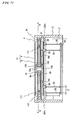
- FIG. 71 is a longitudinal cross section showing a
sixteenth embodiment of the present invention;
- FIG. 72 is a schematic lateral cross section taken along
the line A-A of FIG. 71;
- FIG. 73 is a block diagram showing the entire apparatus
including the operation system according to the embodiment
disclosed in FIG. 71;
- FIG. 74 is a diagram showing the control contents of a
plurality of energizing control modes K1-K4 executed by the
table driving control means of the embodiment disclosed in FIG.
71 and the moving directions (transporting directions of the
movable table) of the entire driven magnets;
- FIG. 75 is a diagram showing the control contents of a
plurality of energizing control modes K5-K8 executed by the
table driving control means of the embodiment disclosed in FIG.
71 and the moving directions (transporting directions of the
movable table) of the entire driven magnets;
- FIG. 76 is a diagram showing the control contents of a
plurality of energizing control modes K9-K10 (rotating action)
executed by the table driving control means of the embodiment
disclosed in FIG. 71 and the moving directions (transporting
directions of the movable table) of the entire driven magnets;
- FIG. 77 is an illustration of a seventeenth embodiment
of the present invention, which is the case where the
electromagnetic braking mechanism is mounted to both the
movable table and the table holding mechanism;
- FIG. 78 is an illustration showing a positioning example
of the braking magnets in the electromagnetic braking mechanism
in the state where the bottom part of the main body is removed
from the main body and the braking plate is also removed; and
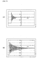
- FIGS. 79 are characteristic diagrams showing the results
of comparison between the braking characteristic of the
seventeenth embodiment and that of a conventional case.
-
BEST MODE FOR CARRYING OUT THE INVENTION
-
In the followings, embodiments of the present invention
will be described by referring to accompanying drawings.
[First Embodiment]
-
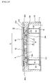
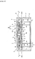
A first embodiment of the present invention is shown in
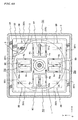
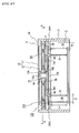
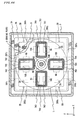
FIG. 1 to FIG. 18. In FIG. 1 to FIG. 18, numeral reference 1
is a movable table and numeral reference 2 is a table holding
mechanism. The table holding mechanism 2, as shown in FIG. 1,
is disposed in the lower part of a case main body (main body
part) 3. The table holding mechanism 2 is configured to allow
the movable table 1 to move in an arbitrary direction on a same
plane, while holding the movable table 1 in the state where
original position returning force is applied to the movable
table 1.
-
The table holding mechanism 2 is supported by the case
main body 3 which is the main body part.
-
The case main body 3 according to the embodiment is formed
in a box shape with the top and bottom being opened as shown
in FIG. 1.
-
Numeral reference 4 is an electromagnetic driving means.
The electromagnetic driving means 4 has a function of applying
a moving force (feed) to the movable table 1, with the main part
being held by the case main body 3 side. Numeral reference 3A
is a main-body protrusion which is provided in the periphery
of the inner wall of the case main body 3 by being protruded
in the inward direction.
-
The electromagnetic driving means 4 according to the
embodiment is disposed between the movable table 1 and an
auxiliary table 5 which will be described later.
-
The auxiliary table 5 is made of a magnetic material, and
is mounted by being connected to the movable table 1 by facing
and also being in parallel with respect to the movable table
1 with a prescribed space in between. Further, the table
holding mechanism 2 is mounted to the auxiliary table 5 side
so as to hold the movable table 1 through the auxiliary table
5.
-
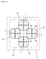
The electromagnetic driving means 4 comprises: four
driven magnets 6 in a square shape being fixed to prescribed
positions of the auxiliary table 5; cross-in-square-shape
driving coils 7 having a cross-shape coil side being disposed
by facing each driven magnet 6, which applies a prescribed
moving force (feed) to the movable table 1 by the magnetic force
along a prescribed moving direction by associating with each
driven magnet 6; and a fixing plate 8 which is mounted to the
auxiliary table 5 on the movable table 1 side for holding the
cross-in-square-shape driving coil 7 at a fixed position. This
fixing plate 8 is formed with magnetic member. Although the
driving coil 7 is illustrated as a closed circuit for clearly
showing the shape of the rolled end part, the driving coil 7
is wound in solenoid form having two terminals on both ends for
energization so as to generate the magnetic force by the
energization. This manner of illustrating the driving coil
applies also to each embodiment as will be described
hereinafter.
-
Further, a plurality of the cross-in-square-shape
driving coils 7 described above comprise a braking plate 9 made
of nonmagnetic metallic member (for example, a copper member
with less electric resistance), respectively, on the end faces
facing the driven magnets 6. The braking plate 9 is adjacent
to the pole face of the facing driven magnet 6. The braking
plates 9 are fixed to the fixing plate 8 side
-
This will be described in more detail.
[Movable Table and Auxiliary Table]
-
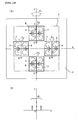
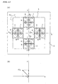
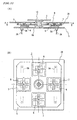
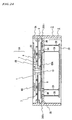
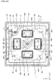
In FIG. 1 to FIG. 4, the movable table 1 is formed in a
circular shape and the auxiliary table 5 is formed in a square
shape. The auxiliary tale 5 is disposed by facing and in
parallel with respect to the movable table 1 with a prescribed
space in between, and the center is integrally connected to the
movable table 1 through a connecting brace 10. Thus, the
movable table 1 can integrally move and integrally rotate with
the auxiliary table 5 while maintaining the parallel state
therebetween.
-
The connecting brace 10 is a connecting member for
connecting the movable table 1 and the auxiliary table 5, and
is formed to have an H-letter shaped cross section with flange
parts 10A, 10B provided on both ends. In the center of both
ends on the outer side, provided are protrusions 10a, 10b for
engaging with positioning holes 1a, 5a formed in each center
of the movable table 1 and the auxiliary table 5.
-
The movable table 1 and the auxiliary table 5 are
integrated by being positioned through the protrusions 10a, 10b
and the flange parts 10A, 10B and fixed to the connecting brace
10. For this integration, adhesive is used in this embodiment.
However, they may be joined partially by welding or the
protrusions 10a, 10b may be press-fitted into the positioning
holes 1a, 5a and other parts may be integrated by adhesive,
welding or the like. Further, either the movable table 1 or
the auxiliary table 5 may be fixed to the flange part 10A or
10B of the connecting brace 10 through a screw to be removable.
In this case, after being fixed by a screw, a number of knock
pins may be engaged and driven in between both tables for
positioning fixation (not shown). Thereby, the movable table
1 and the auxiliary table 5 can be surely integrated.
[Table Holding Mechanism]
-
The table holding mechanism 2 according to the embodiment
has a function of, while holding the movable table 1, moving
it in any directions at will on the same plane without changing
the height position. This is carried out through the auxiliary
table 5.
-
The table holding mechanism 2 is obtained by applying a
link mechanism three-dimensionally. Four pairs of two piano
wires placed with a prescribed space in between are prepared
beforehand by corresponding to the corner parts on the periphery
of the edge portion of the auxiliary table 5. Each pair of the
four pairs of piano wires is provided facing upward direction
in each of the four-corner parts of an intermediate plate 2G
in a quadrangular shape. The table holding mechanism 2 holds
the auxiliary table 5 from the bottom side through the four piano
wires 2A placed on the inner side and suspends the intermediate
plate 2G to be swingable from the main body part 3 through the
four piano wires 2B placed on the outer side. The two piano
wires may be any other members as long as they are rod-type
elastic wire materials with a sufficient and appropriate
rigidity for supporting the movable table 1 and the auxiliary
table 5.
-
Thereby, the auxiliary table 5 (that is, the movable table
1) is held stably in the air by the intermediate plate 2G and
each of the four piano wires 2A, 2B. Thus, it is movable in
any directions at will in the horizontal plane while maintaining
the same height position as will be described later. The
auxiliary table 5 (that is, the movable table 1) can be rotated
on the same plane in substantially the same manner.
-
This will be described in more detail.
-
The table holding mechanism 2 comprises: the four
table-side piano wires 2A planted in each of the four corner
parts on the peripheral edges of the auxiliary table 5 towards
the downward direction in FIG. 1; the intermediate plate 2G
mounted to the lower end part of each table-side piano wire 2A
in FIG. 1; and the main-body-side piano wires 2B being mounted
on the outer side of the table-side piano wires 2A, which are
configured to suspend the intermediate plate 2G from the main
body part 3 side.
-
As for the four table-side piano wires 2A, the upper end
parts in FIG. 1 are fixed to the auxiliary table 5 and the lower
end parts are fixed to the intermediate plate 2G. Numeral
references 5A, 5B are lower protrusions provided in two areas
on the lower side of the auxiliary table 5. The fixing positions
of the table-side piano wires 2A are set by the lower protrusions
5A, 5B.
-
On the outer side of each of the four table-side piano
wires 2A, the main-body-side piano wires 2B are provided
individually and in parallel with each other with a prescribed
space S in between. As for the main-body-side piano wires 2B,
the lower end parts are fixed to the intermediate plate 2G in
the same manner as the case of the table-side piano wires 2A,
and the upper end parts are fixed to main-body-side protrusions
3B provided in the inner wall of the case main body 3.
-
Each of these piano wires 2A, 2B is formed with a rod-type
elastic wire material with a sufficient and appropriate
rigidity for supporting the movable table 1 and the auxiliary
table 5.
-
Thereby, the movable table 1, together with the auxiliary
table 5, is supported by the four table-side piano wires 2A on
the inner side on the intermediate plate 2G, and is allowed to
move in parallel and to rotate within the plane within the limit
of elasticity of the four table-side piano wires 2A according
to a principle of the link mechanism.
-
In the meantime, the intermediate plate 2G is suspended
from the main-body-side protrusions 3B by the four table-side
piano wires 2B placed on the outer side on the intermediate plate
2G. Thus, it is also allowed to move in parallel with respect
to the case main body 3 and to rotate within the plane in the
same manner.
-
Therefore, when the auxiliary table 5 (that is, the
movable table 1) moves or rotates within the plane upon
receiving the external force, each of the piano wires 2A, 2B
on the table side and case main body side is elastically deformed
simultaneously as shown in FIG. 17 which will be described later,
and the intermediate plate 2G moves vertically while
maintaining the parallel state. Thus, when the auxiliary table
5 (that is, the movable table 1) moves or rotates within the
plane upon receiving the external force, changes in the height
position are absorbed since the height of the intermediate plate
2G changes vertically.
-
Thereby, the movable table 1 can move in any directions
within the limit of elasticity of each piano wire 2A, 2B while
maintaining the same height, when moved by receiving the
external force.
-
Each of the piano wires 2A, 2B on the table side and the
case main body side has the same diameter and same elasticity,
and each of the effective lengths L is set to be completely the
same. Further, although each of the piano wires 2A, 2B is
provided along the lateral direction as shown in FIG. 1 and FIG.
3, for example, they may be provided in positions other than
the positions shown in FIG. 2 as long as they are disposed on
the X-Y plane in the positions to be in line-symmetrical to each
other with respect to the X-axis and Y-axis.
-
There is elastic stress generated uniformly in each of
the piano wires 2A, 2B for moving the movable table 1. Thus,
it is advantageous in respect that the movable table 1 can be
smoothly moved including the return of the movable table 1 to
the original position.
-
As described above, in the table holding mechanism 2, all
the piano wires 2A, 2B in each pair are identically deformed
when, for example, the entire auxiliary table 5 is slide-moved
in the same direction. In this case, the main-body-side piano
wire 2B is elastically deformed while the end part is being held
so that, by the deformation of the table-side piano wire 2A which
is elastically deformed in the same manner, the height position
of the auxiliary table 5 becomes unchanged. Instead, the height
position of the intermediate plate 2G which is commonly
supported by the both piano wires 2A, 2B changes.
-
In other words, the intermediate plate 2G absorbs the
change in the height position caused by the deformation of the
both piano wires 2A, 2B. Thereby, the auxiliary table 5 (that
is, the movable table 1) is slide-moved within the same plane
without changing the height as a whole. In this case, when the
auxiliary table 5 is released from the external force, the
auxiliary table 5 is returned straight to the original position
by the spring action (restoring force) of each piano wire 2A,
2B.
-
Moreover, when the auxiliary table 5 (that is, the movable
table 1) is rotationally driven on the same plane, the auxiliary
table 5 (that is, the movable table 1) rotates within the same
plane while maintaining substantially the same heights as a
whole due to the same reasons. In this case, when the auxiliary
table 5 is released from the external force, the auxiliary table
5 is also returned straight to the original position by the
spring action (restoring force) of each piano wire 2A, 2B.
[Electromagnetic Driving Means]
-
Between the movable table 1 and the auxiliary table 5,
as described above, an electromagnetic driving means 4 is
mounted which supplies a prescribed moving force to the movable
table 1 through the auxiliary table 5 (see FIG. 1).
-
The electromagnetic driving means 4 according to the
embodiment comprises: four driven magnets (permanent magnets
are used in this embodiment) 6 mounted on the auxiliary table
5; four cross-in-square-shape driving coils 7 for generating
a prescribed electromagnetic force to the movable table 1
towards a prescribed moving direction through each driven
magnet 6; and a fixing plate 8 for holding each
cross-in-square-shape driving coil 7.
-
As shown in FIG. 1, the fixing plate 8 is mounted to the
auxiliary table 5 on the movable table 1 side (between the
auxiliary table 5 and the movable table 1) and its periphery
is fixed to the case main body 3 to be mounted thereto. As for
the fixing plate 8, only the both end parts on the left and right
sides in FIG. 1 may be fixed to the case main body 3 to be mounted.
In the center of the fixing plate 8, formed is a through-hole
8A for allowing the parallel movement within a prescribed range
of the connecting brace 10. Although the through-hole 8A
according to the embodiment is formed in a circular shape, it
may be in a quadrangular-shape or other shapes. In short, the
through-hole 8A of the fixing plate 8 may be in any shapes as
long as it is the shape which allows the movement of the
connecting brace 10.
-
As described above, the entire periphery of the fixing
plate 8 is held by the main-body-side protrusion 3. In this
case, for strong integration, the fixing plate 8 and the
main-body-side protrusions 3A may be integrated by knock pins
or the like after being screwed, or may be integrated by welding
or the like. With this, it is possible to smoothly correspond
to the displacement or movement of the movable table 1 by micron
(µ) unit without generating a position shift of the fixing plate
8 with respect to the case main body 3.
-
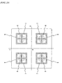
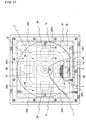
As shown in FIG. 2 and FIG. 3, the four driven magnets
6 according to the embodiment are formed with permanent magnet
whose surface facing the driving coil 7 is formed in a square
shape.
-
Here, in order to control the position shift of the movable
table 1, a plurality of axes are set by being equally divided
in the circumferential direction with the reference being an
axis passing through the origin which is set on the same plane
where the movable table 1 moves. In the case of this embodiment,
the origin is set to coincide with the center of the fixing plate
8.
-
In the embodiment shown in FIG. 2 and FIG. 3, four axes
are set by being divided equally into four in the
circumferential direction with the reference being an axis
passing through the origin which is set on the same plane where
the movable table 1 moves. A pair of two axes which pass through
the origin and extend in the opposite direction from each other
are referred to as the X axis and Y axis, respectively, and the
directions consistent with the X axis and Y axis are supposed
to be the X direction and Y direction. Therefore, the X
direction and Y direction cross at right angles at the origin.
-
Further, the position of the movable table 1 as the
starting point of the movement is set as the center position
of the connecting brace 10 when the movable table 1 is on the
main body part 3 under a free state without receiving an external
force, that is, the center position of the movable table 1. The
center position of the fixing plate 8 and the origin at which
the X-Y directions cross each other are made to coincide with
each other.
-
As shown in FIG. 2 and FIG. 3, the four driven magnets
6 are respectively disposed and fixed on the auxiliary table
5 at the positions in the X-Y directions (on the four axes) being
away from the origin by the same distance.
-
In the positions opposing the four driven magnets 6, the
cross-in-square-shape driving coils 7 are fixed and mounted to
prescribed positions on the fixing plate 8 by individually
corresponding to the four driven magnets 6. The
cross-in-square-shape driving coil 7 has a cross-shape coil
side in its center along the X-Y axes, and supplies a moving
force (feed) to the movable table 1 along a prescribed moving
direction by the mutual magnetic effect between the magnetic
force generated by energization and the magnetic force of each
driven magnet 6.
-
In this case, as for the facing direction of the four
driven magnets 6 according to the embodiment, the magnetic pole
on the side facing the cross-in-square-shape driving coil 7 on
the X axis is set as the north pole and the one on the Y axis
as the south pole, respectively (see FIG. 2 and FIG. 3).
-
Thus, the magnetic force generated between the magnetic
force which is generated in the cross-shape coil side of the
driving coil 7 in the longitudinal direction or the lateral
direction and the magnetic force of the driven magnet 6 are
always set to be in the X or Y direction, and the resultant force
always becomes the maximum value. Thereby, the generated
magnetic force can be effectively outputted as the driving force
of the movable table 1.
-
As for the cross-in-square-shape driving coil 7, the size
is set so that the cross-shape coil side provided inside allows
the driven magnets 6 to move in the maximum moving range.
-
Therefore, the electromagnetic force of the
cross-in-square-shape driving coil 7 generated between the four
driven magnets 6 can be surely outputted to the auxiliary table
5 as a moving force in a prescribed direction through the driven
magnet 6, since the cross-in-square-shape driving coils 7 are
fixed in the prescribed positions on the fixing plate 8.
[Driving Coil in Cross-in-Square Shape]
-
The cross-in-square-shape driving coil 7 forming the
main part of the electromagnetic driving means 4 is formed with,
as shown in FIG. 5 for example, four small angular coils 7a,
7b, 7c, 7d, which can be individually energized. The coil parts
on the inner side of the four small angular coils 7a, 7b, 7c,
7d, which abut with each other in cross-shape form the
cross-shape coil sides described above.
-
Thereby, by controlling the switching of the energizing
directions of each small angular coils 7a-7d by an operation
control system from outside, which will be described later, the
electric current flowing in the cross-shape part inside the
cross-in-square-shape driving coil 7, for example, can be
energized by specifying in either the longitudinal direction
or lateral direction of the figure (including the positive
direction or the reverse direction). Thereby, it is possible
to output the electromagnetic force (reaction force) to the
driven magnets 6 disposed in correspondence for pressing them
to a prescribed direction according to Fleming's left-hand
rule.
-
By combining the directions of the electromagnetic force
generated in the four small angular coils 7a-7d, the cross-shape
coil side parts positioned on the inner sides of the
cross-in-square-shape driving coils 7 are energized in either
the longitudinal direction or the lateral direction, etc.
Thereby, the electromagnetic driving force is outputted to the
corresponding driven magnets 6 in a prescribed direction. Thus,
by the resultant force of the electromagnetic driving forces
generated in the four driven magnets 6, the moving force is
supplied to the auxiliary table 5 towards any directions
including rotating action on the X-Y axes.
-
A series of energizing control methods for the four small
angular coils 7a-7d will be described in detail in the
description of a program storage 22 (FIG. 6, FIG. 8) which will
be described later.
-
Further, the four small angular coils 7a-7d may be hollow
coils or may be the ones having conductive magnetic materials
such as ferrite being filled inside. In FIG. 5, the part on
the inner side of the coil, which is filled with slash lines,
shows a flux linkage region.
-
Numeral reference 9 is a braking plate mounted to the
cross-in-square-shape driving coil 7 side by adjacently facing
the driven magnet 6.
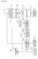
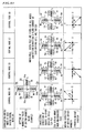
[Position Detecting Sensor Mechanism]
-
The moving state of the auxiliary table 5 (that is, the
movable table 1) driven by the electromagnetic driving means
4 is detected by a position detecting sensor mechanism 25.
-
The position detecting sensor mechanism 25 shown in FIG.
6 has a configuration, comprising: a capacity sensor group 26
having a plurality of capacitance detection electrodes (eight
electrodes in the embodiment); and a positional information
arithmetic circuit 27 which converts a plurality of capacity
change components detected by the capacity sensor group 26 into
voltage and transmits the voltage to a table driving control
means 21 (which will be described later) as a positional change
information after carrying out a prescribed arithmetic
operation.
-
The positional information arithmetic circuit 27
comprises: a signal conversion circuit 27A for individually
converting a plurality of the capacity change components
detected by the capacity sensor group 26 into the voltage; and
a position signal arithmetic circuit 27B which converts the
voltage signals of a plurality of the capacity change components
converted by the signal conversion circuit 27 to a position
signal VX in the X direction and a position signal VY in the
Y direction for indicating the position on the X-Y coordinates
by carrying out a prescribed arithmetic operation, and also
outputs a rotation angle signal by carrying out the arithmetic
operation.
-
As shown in FIG. 1 to FIG. 4, the group 26 of a plurality
of capacity sensors comprises: eight angular capacity detection
electrodes 26X1, 26X2, 26X3, 26X4, 26Y1, 26Y2, 26Y3, 26Y4
provided with a prescribed space in between on the top face of
the main-body-side protrusions 3B by facing the bottom face part
of the periphery of the auxiliary table 5; and a common electrode
(not shown) with a relatively wide width being provided to the
bottom face part of the periphery of the auxiliary table 5 by
corresponding thereto.
-
Among each of the above-described capacity detection
electrodes 26X1, 26X2, 26X3, 26X4, 26Y1, 26Y2, 26Y3, 26Y4, the
capacity detection electrodes 26X1, 26X2 are mounted vertically
in the right-end part of FIG. 2 and FIG. 3 with a prescribed
space in between, while the capacity detection electrodes 26X3,
26X4 are mounted vertically in the left-end part of FIG. 2 and
FIG. 3 with a prescribed space in between.
-
Among each of the above-described capacity detection
electrodes 26X1, 26X2, 26X3, 26X4, 26Y1, 26Y2, 26Y3, 26Y4, the
capacity detection electrodes 26Y1, 26Y2 are mounted laterally
in the upper-end part of FIG. 2 and FIG. 3 with a prescribed
space in between, while the capacity detection electrodes 26Y3,
26Y4 are mounted laterally in the lower-end part of FIG. 2 and
FIG. 3 with a prescribed space in between.
-
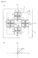
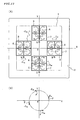
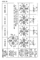
For example, when the auxiliary table 5 (that is, the
movable table 1) is moved in a direction of arrow F (in the
upper-right direction in the figure) as shown in FIG. 7(A) by
a feeding force from the electromagnetic driving means 4, in
the embodiment, the capacity change components detected by the
capacity detection electrodes 26X1, 26X2 (26Y1, 26Y2) on one
side and the capacity detection electrodes 26X3, 26X4 (26Y3,
26Y4) on the other side positioned on both sides (and in vertical
direction) of the auxiliary table 5 are transmitted to the
position signal arithmetic circuit 27B after being converted
to voltage by the signal conversion circuit 27A. Then, each
of the converted voltage is inputted by the position signal
arithmetic circuit 27B for differentially outputting it as the
position signal VX in the X direction and the position signal
VY in the Y direction.
-
When the auxiliary table 5 is rotated in an arrow direction
as shown in FIG. 7(B) by a feeding force from the electromagnetic
driving means 4, in the embodiment, each section operates and
functions in the same manner as that of the above-described case
for differentially outputting a prescribed rotation angle
signal by converting the change components into the voltage.
-
Therefore, in the embodiment, noise added simultaneously
to each capacity detection electrode on the left and right sides
(and top and bottom) in FIG. 3 can be cancelled by the
differential output (for example, obtaining the difference in
the capacity change detected by the capacity detection
electrodes disposed in one end and the other end in the X-axis
direction: external noise eliminating function). At the same
time, after converting the measured value to the voltage, the
change amount is added to be outputted (that is, the reduced
amount is subtracted as a minus component, e.g., A - (-A) = 2A).
Therefore, it is advantageous in respect that the positional
information of the auxiliary table 5 (movable table 1) can be
outputted in highly sensitive manner.
[Operation Control System]
-
In the embodiment, provided to the electromagnetic
driving means 4 is an operation control system 20 which
restricts the movement or the rotation of the movable table 1
by individually drive-controlling a plurality of the
cross-in-square-shape driving coils 7 (see FIG. 6).
-
As shown in FIG. 6, the operation control system 20
comprises: a table driving control means 21 which individually
drives each of a plurality of the cross-in-square-shape driving
coils 7 of the electromagnetic driving means 4 according to a
prescribed control mode for controlling the movement of the
movable table 1 in a prescribed direction; a program storage
22 being provided along with the table driving control means
21, to which a plurality of control programs for a plurality
of control modes are provided and in which the moving direction,
rotation direction, the operation amount and the like of the
movable table 1 are specified; and a data storage 23 to which
prescribed data and the like are stored to be used at the time
of executing each control program.
-
In the table driving control means 21, provided is an
operation command input section 24 for giving a command of a
prescribed control operation to each of a plurality of the
cross-in-square-shape driving coils 7. The positional
information of the movable table 1 during the movement and after
the movement is detected by the position detecting sensor
mechanism 25 and arithmetic-processed in a highly sensitive
manner to be transmitted to the table driving control means 21
as will be described later.
-
The table driving control means 21 according to the
embodiment comprises a main control section 21A and a coil
driving control section 21B. The main control section 21A
operates according to the command from the operation command
input section 24 and has a function of selecting a prescribed
control mode from the program storage 22 and controlling to
energize a prescribed electric current to each of a plurality
of the cross-in-square-shape driving coils 7. The coil driving
control section 21B has a function of controlling to drive
prescribed four cross-in-square-shape driving coils 7, 7 ---
simultaneously and individually according to the control mode
set by the main control section 21A.
-
The main control section 21A, in addition to the
above-described function, also has a function of calculating
the position of the movable table 1 according to the input
information from the position detecting sensor mechanism 25 for
detecting the table position or carrying out other various
arithmetic operations.
-
Numeral reference 4G is a power circuit for supplying a
prescribed current to each of a plurality of cross-in-square
driving coils 7 of the electromagnetic driving means 4.
-
The table driving control means 21 comprises: a position
shift calculating function which is for carrying out a
prescribed arithmetic operation through inputting the
information from the position detecting sensor mechanism 25 and,
based on this, calculating the difference between with the
reference position information of the target position set by
the operation command input section 24 beforehand; and a table
position correcting function which controls to transport the
movable table 1 to the reference position of the target position
which is set beforehand by driving the electromagnetic driving
means 4 based on the calculated position shift information.
-
Thus, in the embodiment, when the moving direction of the
movable table 1 is shifted by disturbance or the like, the
movable table 1 is controlled to be transported in a prescribed
direction by correcting the position shift. Thereby, the
movable table 1 is transported to the target position set
beforehand promptly and in highly precise manner.
[Program Storage]
-
The table driving control means 21 is configured to
individually drive-control the four cross-in-square-shape
driving coils 7 of the electromagnetic driving means 4
individually according to a prescribed control program (a
prescribed control mode which is a combination of a prescribed
energizing pattern and the selection), which is stored in the
program storage 22 beforehand.
-
That is, in the embodiment, stored in the program storage
22 is the program for executing the basic four energizing
patterns for each of the four cross-in-square-shape driving
coils 7, 7 --- (see FIG. 6, FIG. 8).
-
FIG. 8 shows, respectively, four types of energizing
patterns A, B, C, D for the four small angular coils 7a, 7b,
7c, 7d of the cross-in-square-shape driving coil 7 (on a stator
side), the direction of the electric current generated at this
time in the cross-shape side part of each cross-in-square-shape
driving coil, and the direction of the electromagnetic driving
force (thrust) correspondingly generated in the driven magnet
(permanent magnet) 6 on a needle side.
-
In FIG. 8, in the case of the energizing pattern A, a
counterclockwise electric current is supplied to the small
angular coils 7a, 7b on one side and a clockwise electric current
is supplied to the small angular coils 7c, 7d on the other side,
respectively. Thereby, in the cross-shape coil side part
positioned in the center, the magnetic fluxes to be outputted
outside are collectively added or offset. As a result, it
becomes to be under the state similar to the case where only
an electric current IA in the positive direction of the X axis
is supplied.
-
In the energizing pattern B, as shown in the figure, each
of the small angular coils 7a-7c is individually energized.
Thereby, it becomes to be under the state similar to the case
where only an electric current IB in the negative direction of
the X axis is supplied. In the energizing pattern C, as shown
in the figure, each of the small angular coils 7a-7c is
individually energized. Thereby, it becomes to be under the
state similar to the case where only an electric current IC in
the positive direction of the Y axis is supplied. Similarly,
in the energizing pattern D, as shown in the figure, each of
the small angular coils 7a-7c is individually energized.
Thereby, it becomes to be under the state similar to the case
where only an electric current ID in the negative direction of
the Y axis is supplied.
-
The four energizing patterns A, B, C, D are executed
according to a prescribed control program stored beforehand in
the program storage 22.
-
The white arrows shown in FIG. 8 respectively show the
direction of the electromagnetic driving force (thrust)
generated between with the driven magnet (permanent magnet) 6
on the needle side by corresponding to the energizing patterns
A, B, C, D.
-
In this case, each corresponding electromagnetic force
is generated in the energizing coil side part of the
cross-in-square-shape driving coil 7 according to Fleming's
left-hand rule. However, since the cross-in-square-shape
driving coil 7 is fixed on the fixing plate 8, the reaction force
is generated as the electromagnetic driving force (thrust)
towards the driven magnet (permanent magnet) 6 side.
-
The white arrows shown in FIG. 8 show the reaction force
(electromagnetic driving force). The direction of the
reaction force (the electromagnetic driving force) is reversed
according to the types of the magnetic poles, that is, north
or south, of the driven magnet 6.
-
In the program storage 22, stored is each operation
program for the first to fourth control modes for moving the
movable table 1 in both the positive and negative directions
of the X axis and both the positive and negative directions of
the Y axis on the X-Y plane supposed with the origin being the
center of the fixing plate 8, for the fifth to eighth control
modes for moving the movable table 1 in a prescribed direction
within each quadrant set on the X-Y plane, and for the ninth
and tenth control modes for rotating the movable table 1 at a
prescribed position in the clockwise direction or the
counterclockwise direction.
-
FIG. 9 to FIG. 13 show, respectively, the function of each
cross-in-square-shape driving coil 7 and the operation state
of the auxiliary table (the movable table 1) at the time of
executing the operation program for each of the first to tenth
control modes.
-
FIGS. 9(A), (B) show the state of executing the first
control mode. As shown in the figures, in the first control
mode, the two cross-in-shape driving coils 7, 7 on the X axis
are energized by the method of the current pattern D,
respectively, while the two cross-in-shape driving coils 7, 7
on the Y axis are energized by the method of the current pattern
C. In FIG. 9(A), numeral references N, S indicate the type of
the magnetic poles of each driven magnet (permanent magnet) 6.
-
As a result, in the first control mode, the
electromagnetic driving force is generated in each driven
magnet (permanent magnet) 6 in the directions of arrows FX1,
FX2, FX3, FX4. Thereby, the auxiliary table 5 is driven towards
the positive direction (an arrow +FX) on the X axis.
-
FIG. 9(B) shows an example of the direction on the X-Y
coordinates in the case where the same electromagnetic driving
force is generated in each of the cross-in-square-shape driving
coils 7, 7 ---. According to this, it is important, especially,
to generate the same magnitude of the driving force to each of
the cross-in-square-shape driving coils 7, 7 on the Y axis when
transporting the auxiliary table 5 in the positive direction
on the X axis.
-
The case of the second control mode is for transporting
the auxiliary table 5 in the negative direction (not shown) on
the X axis, so that the current pattern to be supplied to each
of the cross-in-square-shape driving coils 7, 7 --- may be set
completely inversely with respect to the case of the first
control mode.
-
That is, in the second control mode, the two
cross-in-square-shape driving coils 7, 7 on the X axis are
energized by the method of the current pattern C, respectively,
and the two cross-in-square-shape driving coils 7, 7 on the Y
axis are energized by the method of the current pattern D,
respectively. Thereby, the auxiliary table 5 is smoothly
transported to the negative direction on the X axis (not shown) .
-
FIGS. 10(A), (B) show the state where the third control
mode is executed. As show in the figures, in the third control
mode, the two cross-in-square-shape driving coils 7, 7 on the
X axis are energized by the method of the current pattern A,
respectively, and the two cross-in-square-shape driving coils
7, 7 on the Y axis are energized by the method of the current
pattern B, respectively.
-
As a result, by the third control mode, the
electromagnetic driving force is generated in each of the driven
magnet (permanent magnet) 6 in the directions of arrows FY1,
FY2, FY3, FY4. Thereby, the auxiliary table 5 is driven towards
the positive direction (arrow + FY) on the Y axis.
-
FIG. 10(B) shows an example of the direction of the
resultant force on the X-Y coordinates in the case where the
same electromagnetic driving force is generated in each of the
cross-in-square-shape driving coils 7, 7 ---. According to
this, it is important, especially, to generate the same
magnitude of the driving force in each of the
cross-in-square-shape driving coils 7, 7 on the X axis when
transporting the auxiliary table 5 in the positive direction
on the Y axis.
-
The case of the fourth control mode is for transporting
the auxiliary table 5 in the negative direction (not shown) on
the Y axis, so that the electric current pattern to be supplied
to each of the cross-in-square-shape driving coils 7, 7 --- may
be set completely inversely with respect to the case of the third
control mode.
-
That is, in the fourth control mode, the two
cross-in-square-shape driving coils 7, 7 on the X axis are
energized by the method of the current pattern B, respectively,
and the two cross-in-square-shape driving coils 7, 7 on the Y
axis are energized by the method of the current pattern A,
respectively. Thereby, the auxiliary table 5 is smoothly
transported in the negative direction on the Y axis (not shown) .
-
FIGS. 11(A) , (B) show the state where the fifth control
mode is executed. As show in the figures, in the fifth control
mode, the two cross-in-square-shape driving coils 7, 7 on the
X axis are energized by the method of the current pattern D,
respectively, and the two cross-in-square-shape driving coils
7, 7 on the Y axis are energized by the method of the current
pattern B, respectively.
-
As a result, by the fifth control mode, the
electromagnetic driving force is generated to the two driven
magnets (permanent magnets) 6 on the X axis in the directions
of arrows FX1, FX3, and the electromagnetic driving force is
generated to the two driven magnets (permanent magnets) 6 on
the Y axis in the directions of arrows FY2, FY4. Thereby, the
auxiliary table 5 is driven towards the first quadrant direction
(arrow FXY) from the center point on the X-Y axes.
-
FIG. 11(B) shows an example of the direction of the
resultant force on the X-Y coordinates in the case where the
same electromagnetic driving force is generated in each of the
cross-in-square-shape driving coils 7, 7 ---. According to
this, when driving the auxiliary table 5 in the direction (arrow
FXY) towards the first quadrant direction from the center point
on the X-Y axes, it is possible to change the moving direction
by appropriately setting the magnitude of the current value
supplied to each of the cross-in-shape driving coils 7, 7 ---.
The magnitude of the electric current to be supplied is set and
controlled by the main control section 21A.
-
The case of the sixth control mode is for transporting
the auxiliary table 5 towards the third quadrant direction (not
shown) from the center point on the X-Y axes, so that the current
pattern to be supplied to each of the cross-in-square-shape
driving coils 7, 7 --- may be set completely inversely with
respect to the case of the fifth control mode.
-
That is, in the sixth control mode, the two
cross-in-square-shape driving coils 7, 7 on the X axis are
energized by the method of the current pattern C, respectively,
and the two cross-in-square-shape driving coils 7, 7 on the Y
axis are energized by the method of the current pattern B,
respectively. Thereby, the auxiliary table 5 is smoothly
transported towards the third quadrant direction from the
center point on the X-Y axes (not shown).
-
FIGS. 12(A), (B) show the state where the seventh control
mode is executed. As show in the figures, in the seventh control
mode, the two cross-in-square-shape driving coils 7, 7 on the
X axis are energized by the method of the current pattern C,
respectively, and the two cross-in-square-shape driving coils
7, 7 on the Y axis are energized by the method of the current
pattern B, respectively.
-
As a result, in the seventh control mode, the
electromagnetic driving force is generated to the two driven
magnets (permanent magnets) 6 on the X axis in the directions
of arrows -FX1, -FX3, and the electromagnetic driving force is
generated to the two driven magnets (permanent magnets) 6 on
the Y axis in the directions of arrows FY2, FY4. Thereby, the
auxiliary table 5 is driven towards the second quadrant
direction (arrow FYX) from the center point on the X-Y axes.
-
FIG. 12(B) shows an example of the direction of the
resultant force on the X-Y coordinates in the case where the
same electromagnetic driving force is generated in each of the
cross-in-square-shape driving coils 7, 7 ---. According to
this, when driving the auxiliary table 5 in the direction (arrow
FYX) towards the second quadrant direction from the center point
on the X-Y axes, it is possible to change the moving direction
by appropriately setting the magnitude of the current value
supplied to each of the cross-in-shape driving coils 7, 7 ---.
The magnitude of the electric current to be supplied is set and
controlled by the main control section 21A.
-
The case of the eighth control mode is for transporting
the auxiliary table 5 towards the fourth quadrant direction (not
shown) from the center point on the X-Y axes, so that the current
pattern to be supplied to each of the cross-in-square-shape
driving coils 7, 7 --- may be set completely inversely with
respect to the case of the seventh control mode.
-
That is, in the eighth control mode, the two
cross-in-square-shape driving coils 7, 7 on the X axis are
energized by the method of the current pattern D, respectively,
and the two cross-in-square-shape driving coils 7, 7 on the Y
axis are energized by the method of the current pattern A,
respectively. Thereby, the auxiliary table 5 is smoothly
transported towards the fourth quadrant direction from the
center point on the X-Y axes (not shown).
-
FIGS. 13(A), (B) show the state where the ninth control
mode is executed. As show in the figures, the ninth control
mode is for rotating the auxiliary table 5 (that is, the movable
table 1) by a prescribed angle . This control operation allows
the auxiliary table 5 with no center shaft to perform
counterclockwise rotary motions within a prescribed allowable
range and to stop at a prescribed position.
-
That is, in the ninth control mode as shown in FIG. 13,
the cross-in-square-shape coil 7 on the positive axis of the
X axis is energized by the method of the current pattern A, the
cross-in-square-shape coil 7 on the negative axis of the X axis
by the method of the current pattern B, the
cross-in-square-shape coil 7 on the positive axis of the Y axis
by the method of the current pattern D, and the
cross-in-square-shape coil 7 on the negative axis of the Y axis
by the method of the current pattern C, respectively.
-
As a result, in the ninth control mode, the
electromagnetic driving force is generated to each of the driven
magnet (permanent magnet) 6 corresponding to each of the
cross-in-square- shape driving coil 7, 7 ---towards the
directions FY1, -FX2, -FY3, or FX4, which cross at right angles
with each axis, respectively, along the counterclockwise
direction as shown in FIG. 11.
-
Therefore, as shown in FIG. 13(A), by setting the
magnitude of each electromagnetic driving force generated in
each driven magnet (permanent magnet) 6 to be in the same
magnitude P, the auxiliary table 5 without the center shaft can
perform counterclockwise rotary motion within the allowable
range and stop at a prescribed position.
-
In this case, the stop position after the rotary motion
is a balanced point (position after being rotated by a
prescribed angle ) between the entire electromagnetic driving
force and the original position returning force by a spring
action of the table holding mechanism 2. The position is
experimentally specified beforehand as the relation between the
set rotation angle and the electromagnetic driving force, and
is put into a diagram (a map) to be retrievable and stored in
the data storage 23.
-
FIG. 13(B) shows an example of the direction on the X-Y
coordinates in the case where the same electromagnetic driving
force is generated in each of the cross-in-square-shape driving
coils 7, 7 ---. According to this, the auxiliary table 5 (that
is, the movable table 1) is rotated counterclockwise by a
prescribed angle with a center point O on the X-Y axes being
the rotation center and stopped.
-
In this case, the degree of the rotation angle for
setting the stop position after the rotation can be determined
by appropriately setting the magnitude of the same current value
which is supplied to each of the cross-in-square-shape driving
coils 7, 7. The magnitude of the current to be supplied is set
by the main control section 21A.
-
The case of the tenth control mode is for rotating the
auxiliary table 5 (that is, the movable table 1) clockwise.
Thus, in the tenth control mode, the directions of the same
current supplied to each of the cross-in-square-shape driving
coils 7, 7 --- may be set inversely.
-
That is, the cross-in-square-shape driving coil 7 on the
positive axis of the X axis is energized by the method of the
current pattern B, the cross-in-square-shape driving coil 7 on
the negative axis of the X axis by the method of the current
pattern A, the cross-in-square-shape driving coil 7 on the
positive axis of the Y axis by the method of the current pattern
C, and the cross-in-square-shape driving coil 7 on the negative
axis of the Y axis by the method of the current pattern D,
respectively.
-
Thereby, the auxiliary table 5 is smoothly rotated
clockwise by a prescribed angle (not shown).
-
The operation programs for each energizing pattern and
each control operation are stored in the operation program
storage 22 to be outputted, which is provided along the table
driving control means 21. The table driving control means 21
selects one of each operation program according to a command
from the operation command input section 24 and drive-controls
the electromagnetic driving means 4 based thereupon.
[Electromagnetic Braking Mechanism]
-
The electromagnetic braking mechanism comprises braking
magnets and a non-magnetic/conductive braking plate 9, which
face each other and move relatively by synchronizing with the
movement of the movable table 1. Either the braking magnet or
the braking plate 9 is fixed to a prescribed position, while
the other is provided movable by synchronizing with the movement
of the movable table 1, thereby enabling to generate the braking
force based on the magnetic effect between the magnetic force
by eddy current which is generated in the braking plate 9 due
to the movement of the movable table 1 and the magnetic force
of the braking magnet.
-
As the braking magnets of the electromagnetic braking
mechanism according to the embodiment, the driven magnets 6 are
used. In the end face part of the each of the four
cross-in-square-shape driving coils 7 facing the driven magnets
6, as shown in FIG. 14, the metal braking plates 9 made of a
non-magnetic member are fixed adjacent from each other to be
mounted thereto by facing the pole faces of the driven magnets
6, respectively, in the state being isolated from the
peripherals.
-
The electromagnetic braking mechanism comprises a
function of slowly moving the auxiliary table 5 (the movable
table 1) by suppressing a sudden moving action of the auxiliary
tale 5 (the movable table 1).
-
FIG. 14(A) is a fragmentary sectional view of FIG. 1
showing the braking plate 9. Also, FIG. 14(B) is a plan view
taken along the arrow line of A-A in FIG. 14(A).
-
When the auxiliary table 5 to which the four driven magnets
6 are mounted or the movable table 1 rapidly makes a moving action,
electromagnetic braking (eddy-current brake) works between
each driven magnet 6 and each corresponding braking plate 9.
Thereby, the auxiliary table 5 (that is, the movable table 1)
is gradually moved by suppressing the sudden moving action.
-
Generation of the electromagnetic braking (eddy-current
brake) is shown in FIGS. 15(A), (B).
-
In the figures, the braking plate 9 is fixed to the end
part of the cross-in-square-shape driving coil 7 by facing the
north pole of the driven magnet 6.
-
When the auxiliary table 5 rapidly moves at a speed v1
in the right direction of the figure, relatively, the metallic
braking plate 9 (since it is fixed) rapidly moves at the same
speed v2 (= v1) in the left direction of the figure. Thereby,
the electromotive force EV in the magnitude in proportion to
that of the speed v2 is generated inside the braking plate 9
in the direction (upward direction in the figure) shown in FIG.
15(B) according to Fleming's right-hand rule. Thereby, eddy
current which is in bilateral symmetry flows in the directions
of the same arrows.
-
Next, since there is magnetic flux from the north pole
in the region where the electromotive force EV is generated,
a prescribed moving force f1 is generated inside the braking
plate 9 (towards the right direction in the figure) between the
magnetic flux of the driven magnet 6 and the eddy current (in
the direction of the electromotive force EV) inside the braking
plate 9 according to Fleming's left-hand rule.
-
In the meantime, since the braking plate 9 is fixed on
the fixing plate 8, the reaction force f2 of the moving force
f1 is generated on the driven magnet 6 as the braking force,
thereby reversing the direction from that of the moving force
f1. Specifically, the braking force f2 is in the reverse
direction from that of the initial rapid-movement of the driven
magnet 6 (that is, the auxiliary table 5) and, in addition, the
magnitude is proportional to the moving speed of the auxiliary
table 5. Therefore, the rapid movement of the auxiliary table
5 is suppressed by an appropriate magnitude of braking force
f2 to be smoothly moved under the stable state.
-
A prescribed braking force f2 is also generated in the
areas of other braking plates 9 in completely the same manner.
-
Thus, in the auxiliary table 5 comprising the driven
magnets 6, a reciprocal movement is likely to be caused at a
stop position at the time of, for example, making a sudden stop.
However, it is appropriately suppressed for achieving a smooth
and slow movement. Therefore, as a whole, each braking plate
9 effectively functions for enabling to move the auxiliary table
5 (the movable table 1) under the stable state. Further, in
the case where the auxiliary table 5 is reciprocally and
slightly oscillated by oscillation applied from the outside,
it also functions in the same manner for effectively suppressing
the reciprocal and slight oscillation.
-
Each of the metallic braking plate 9 made of a non-magnetic
member, which is mounted to the end face part of each
cross-in-square-shape driving coil 7, as shown in FIG. 16,
constitutes a transformer secondary circuit in the relation
between with each cross-in-square-shape driving coil 7, while
being in a form which is short-circuit through a prescribed low
resistance r (generates eddy current loss).
-
In FIG. 16, K1 is a primary-side winding representing the
cross-in-square-shape driving coil 7 and K2 is a secondary-side
winding corresponding to the braking plate 9. FIG. 16(A) shows
the state where the secondary-side winding part is
short-circuit through the electric resistance component (low
resistance r: generates eddy current loss) inside the braking
plate 9. In this case, inside the braking plate 9, the similar
current (that is, the eddy current in proportion to the
magnitude of the magnetic flux of the driving coil 7) as the
short-circuit state of the secondary-side winding is flown.
The areas to which other braking plates 9 are placed are to be
in completely the same state as well. Moreover, FIG. 16(B)
shows the state without the braking plate 9 (the state where
the secondary-side winding part is open).
-
Therefore, each cross-in-square-shape driving coil 7
constituting the primary-side circuit in this case can
effectively reduce, through the secondary-side short-circuit,
the affect of a large resistance generated by the inductance
component of the coil at the time of start-up (transient). In
this respect, a relatively large current can be supplied from
the starting time so that the electromagnetic driving force can
be quickly outputted between with the driven magnet compared
to the case where there is no braking plate 9.
-
Each braking plate 9 comprises a function of releasing
the heat generated at the time of driving each
cross-in-square-shape driving coil 7. In this respect, it is
possible to set the supplied current in substantially the
constant level for a long time through effectively suppressing
an increase in the resistance and a decrease in the supplied
current value (that is, a decrease in the electromagnetic
driving force) at a high temperature caused by a continuous
operation of the driving coil. Thus, the current control from
outside for the electromagnetic driving force outputted from
the electromagnetic driving means can be continued under the
stable state and the secular change (dielectric breakdown by
the heat) can be effectively suppressed. Thereby, the
durability of the entire apparatus and, moreover, the
reliability of the entire apparatus can be improved.
-
In the embodiment, the braking plate 9 is described by
referring to the case where the braking plates are respectively
mounted to each cross-in-square-shape driving coil 7. However,
the braking plate 9 may be formed as a single braking plate which
commonly works for two or more of the cross-in-square-shape
driving coils 7 and a plurality of the cross-in-square-shape
driving coils 7 may be placed by facing the single braking plate.
[Overall Action of the Embodiment]
-
Next, the overall action of the first embodiment will be
described.
-
In FIG. 6, first, when an operation command for moving
the movable table 1 to a prescribed position is inputted from
the operation command input section 24, the main control section
21A of the table driving control means 21 is immediately started
and the reference positional information of the target position
is selected from the data storage 23 according to the operation
command. At the same time, the control program for a
corresponding prescribed control mode is selected from the
program storage 22. Subsequently, the coil selection driving
control section 21B is started for drive-controlling the four
cross-in-square-shape driving coils 7 of the electromagnetic
driving means 4 according to a prescribed control mode.
-
FIG. 17 and FIG. 18 show the state where the entire
apparatus is operated according to the command to move the
movable table 1 to a prescribed position in the positive
direction of the X-axis, which is inputted from the operation
command input section 24.
-
In this example, the first control mode shown in FIG. 9
is selected as the control mode and, accordingly, the energizing
patterns are selected in the state shown in FIG. 9, respectively,
to each of the four cross-in-square-shape driving coils 7 to
be in operation.
-
In this case, in the stage holding mechanism 2, when a
feed is supplied to the auxiliary table 5 by the electromagnetic
driving means 4 in the right direction of the figure, the
auxiliary table 5 is moved against the elastic force (original
position returning force) of each of the piano wires 2A, 2B.
Then, the auxiliary table 5 (that is, the movable table 1) makes
a stop at a balanced point (target moved position) between the
elastic returning force of each of the piano wires 2A, 2B and
the electromagnetic driving force of the electromagnetic
driving means 4, which is supplied to the auxiliary table 5.
-
In FIG. 17 and FIG. 18, numeral reference T shows the moved
distance.
-
In FIG. 18, the portion with slashed lines shows the
capacity detection electrodes 26X3, 26X4 on one side where the
capacity component is reduced due to the movement of the
auxiliary table 5, while the portion with cross-over slashed
lines shows the capacity detection electrodes 26X1, 26X2 on the
other side where the capacity component is increased due to the
movement of the auxiliary table 5. In FIG. 18, shown is a case
where there is no position shift in the Y direction.
-
During the operation, when the moved position of the
auxiliary table 5 is shifted from the target position due to
disturbance or the like, the actual position after being moved
is detected based on the information on increase/decrease of
the capacity component of the capacity detection electrodes
26X1, 26X2, 26X3, 26X4, and the feedback control for preventing
the position shift is to be carried out.
-
In the meantime, when the electromagnetic driving force
applied to the auxiliary table 5 is released from such a state,
the auxiliary table 5 returns to the original position by the
elastic returning force of the piano wires 2A, 2B.
-
In a series of the operation, in general, the moving action
of the auxiliary table 5 is carried out rapidly in both cases
of the supply control or release control of the electromagnetic
driving force. Therefore, in the auxiliary table 5 (or the
movable table 1), when being stopped at the moved position and
at the stopping position when returned to the original position,
repeating action (reciprocal action) is caused by the inertia
and spring force.
-
However, in the embodiment, the repeating action
(reciprocal action) is suppressed by the electromagnetic
braking current brake generated between the braking plate and
the driven magnet for achieving a smooth movement towards a
prescribed position and achieving a stop-control under the
stable state.
-
In the case where an operation command for moving the
movable table 1 to another prescribed position is inputted from
the operation command input section 24, the main control section
21A of the table driving control means 21 is immediately started
as well, and the reference positional information of the target
position is selected from the data storage 23 according to the
operation command. At the same time, the control program for
a corresponding prescribed control mode is selected from the
program storage 22. Subsequently, the coil selection driving
control section 21B is started for drive-controlling the four
cross-in-square-shape driving coils 7 of the electromagnetic
driving means 4 according to a prescribed control mode.
-
Also in this case, the same control operation and the
braking operation by the braking plate are executed so that the
auxiliary table 5 (movable table 1) is smoothly moved towards
a prescribed position and stopped under the stable state.
-
As described, in the first embodiment, without using a
holding mechanism for moving in X-Y axes in a heavy double
structure which is essential in the case of the related art,
the auxiliary table 5 can be smoothly moved in any directions
on the X-Y plane from the center position (within a prescribed
range) while maintaining the same height position, or can be
rotated on the same plane.
-
Therefore, with the first embodiment, it is possible to
reduce the size and weight of the entire apparatus due to the
simple structure. In this respect, not only enabling to
remarkably improve the portability, but the number of the parts
can be reduced compared to the case of the related art. Moreover,
due to the reduced number of parts, the durability can be
remarkably improved and a skill is not required for adjustment
at the time of assembling, thereby improving the productivity.
-
Even if action of the auxiliary table 5 (movable table
1) to which driven magnets 6 are mounted rapidly changes, the
electromagnetic braking (eddy current brake) force in the
magnitude in proportion to the rapid change works between the
driven magnet 6 and the braking plate 9 made of non-magnetic
metal material, thereby suppressing the rapid action of the
movable table 1 to be smoothly moved in a prescribed direction
under the stable state.
-
As for the braking plates 9, they are simply mounted to
the cross-in-square-shape driving coil 7 by respectively facing
each driven magnet 6. The electromagnetic driving means 4 for
generating the electromagnetic driving force also has a simple
structure comprising the driving magnets 6 mounted to the
auxiliary table 5, and the cross-in-square-shape driving coils
7 mounted to the fixing table 8 facing the driven magnets. Thus,
it enables to reduce the size and weight of the entire apparatus,
thereby achieving the excellent portability. Moreover, the
workability becomes also excellent since there is no special
skill required at the time of assembling.
-
Further, the metallic braking plate 9 made of
non-magnetic member mounted to the end face part of the driving
coil 7 on the driven magnet 6 side, constitutes a circuit similar
to a transformer secondary circuit in the relation between with
the driving coil 7, while being in a form which is short-circuit
through an electric resistance component (generates eddy
current loss) of the braking plate 9.
-
Therefore, in the cross-in-square-shape driving coil 7
constituting the primary circuit, a relatively large current
can be flown compared to the case where the secondary circuit
is in the open state. Thereby, it enables to output a relatively
large electromagnetic force between with the driven magnet
compared to the case without the braking plate 9.
-
Moreover, the braking plate 9 also functions as a
radiation plate so that the secular change (dielectric
breakdown by the heat) due to the continuous operation of the
cross-in-square-shape driving coil 7 can be effectively
suppressed. Thereby, the durability of the entire apparatus,
and the reliability of the entire apparatus can be improved as
a result.
-
The first embodiment has been described by referring to
the case where the driven magnets 6 are mounted on the auxiliary
tale 5. However, the driven magnets 6 may be mounted to the
movable table 1 side and each cross-in-square-shape driving
coil 7 may be provided to prescribed positions on the fixing
table 8 correspondingly. In this case, each
cross-in-square-shape driving coil 7 may be mounted by piercing
through fixing table 8 and the driven magnets 6 may be mounted
on both the movable table 1 side and the auxiliary table 5 side
by facing each cross-in-square-shape driving coil 7.
-
Moreover, the first embodiment has been described by
referring to the case where the cross-in-square-shape driving
coils 7 are mounted as the driving coils. However, in the
present invention, the driving coils are not necessarily
limited to the cross-in-square-shape driving coils but driving
coils in any other form may be used as long as they can perform
the similar functions.
[Second Embodiment]
-
FIG. 19 and FIG. 20 show a second embodiment. The second
embodiment shown in FIG. 19 and FIG. 20 is distinctive in respect
that: a auxiliary table 5 which is mounted in the first
embodiment is omitted; a movable table 31 is directly held by
a table holding mechanism 2; and the movable table 31 is directly
driven by the electromagnetic driving means 4.
-
In FIG. 19 and FIG. 21, numeral reference 31 is a
square-shape movable table. The movable table 31 comprises a
flat circular working plane 31A on its top face.
-
Numeral reference 2 is the same table holding mechanism
as that of the table holding mechanism according to the first
embodiment. The table holding mechanism 2 is disposed in the
lower part of FIG. 19 in the same manner as that of the first
embodiment. The table holding mechanism 2 is configured to
allow the movable table 31 to move in an arbitrary direction
on a same plane, while holding the movable table 31 in the state
where original position returning force can be applied to the
movable table 31.
-
That is, in the second embodiment, the movable table 31
is installed in a case main body 33 through the table holding
mechanism 2 provided inside the case main body 33 as the main
body part.
-
Further, a capacitive position detecting sensor for
constantly detecting the moving position of the movable table
31 is mounted between the movable table 31 and a driving means
holding section (protrusion on the main body side) 33A of the
case main body 33, which will be described later, in the same
manner as that of the first embodiment.
-
Specifically, in the periphery of the edge of the lower
face (bottom face) of the movable table 31 shown in FIG. 19,
a square-shape spacer 31B having a flat face with a prescribed
width is mounted and, on the bottom face part, a common electrode
31Ba of the capacitive position detecting sensor is provided.
Further, the same capacity detection electrode 26X1, 26X2, 26X3,
26X4, 26Y1, 26Y2, 26Y3, 26Y4 as those of the first embodiment
are provided in the same manner as that of the first embodiment
to be mounted onto the top face of the driving means holding
section (the protrusion on the main body side) 33A which will
be described later.
-
In the table holding mechanism 2, in the same manner as
that of the first embodiment, four pairs of two piano wires 2A,
2B (may be any other member as long as it is a rod-type elastic
wire material with a sufficient and appropriate rigidity for
supporting the movable table 1), which are placed with a
prescribed space in between, are prepared beforehand by
corresponding to the peripheral edge portion of the movable
table 31. The four pairs of piano wires 2A, 2B are respectively
provided facing upward direction in each of the four-corner
parts of an intermediate member 2G in a quadrangular shape.
-
It has a configuration in which the movable table 31 is
held from the bottom side through the four piano wires 2A on
the table side placed on the inner side and the intermediate
member 2G is suspended to be swingable from the case main body
33 through the four piano wires 2B on the main body side placed
on the outer side.
-
Thereby, as in the case of the first embodiment, the
movable table 31 can be moved in any directions on the same plane
without changing the height position and, at the same time, it
can be rotated within an allowable range.
-
As shown in FIG. 19, the case main body (main body part)
33 according to the embodiment is formed in a box shape with
the top and bottom being opened.
-
Numeral reference 34 is an electromagnetic driving means.
The electromagnetic driving means 34 is formed to be the same
as the electromagnetic driving means 4 of the first embodiment.
It is disposed on the lower side of the movable table 31 as shown
in FIG. 19 and held by the case main body 33 side, and has a
function of supplying the moving force to the movable table 31.
-
The numeral reference 33A is a driving means holding
section as the protrusion on the main body side formed in the
inner wall periphery of the case main body 33. The
electromagnetic driving means 34 is held by the case main body
33 through the driving means holding section 33A.
-
The top face of the driving means holding section 33A as
shown in FIG. 19 is formed as a flat surface. On this flat
surface, the capacity detection electrodes 26X1, 26X2, 26X3,
26X4, 26Y1, 26Y2, 26Y3, 26Y4 for externally outputting the
poison information of the movable table 31 are mounted as in
the same manner as that of the first embodiment thereby to
function in the same manner.
-
The electromagnetic driving means 34, as in the case of
the first embodiment, comprises: four driven magnets 6 fixed
to be mounted at prescribed positions on the bottom face part
of the movable table 31 as shown in FIG. 19;
cross-in-square-shape driving coils 7 with a cross-shape coil
side being disposed by facing each driven magnet 6 for supplying
a prescribed driving force to each driven magnet 6
electromagnetically along the moving direction of the movable
table 31; and a fixing plate 38 for holding the
cross-in-square-shape driving coils 7 at prescribed positions.
-
The fixing plate 38 is set in parallel to the movable table
31 with a prescribed space in between and provided in the lower
side of the movable table 31 as shown in FIG. 19. The periphery
is supported by the driving means holding section 33A of the
case main body 33.
-
Further, on the end face side of the
cross-in-square-shape driving coil 7 on the driven magnet 6 side,
as in the case of the first embodiment, braking plates 9 made
of non-magnetic metal member are individually provided in
adjacent to the pole face of the driven magnet 6.
-
The braking plate 9 according to the embodiment is fixed
to the end face part of the cross-in-square-shape driving coil
7 and, through the cross-in-square-shape driving coil 7, it is
fixed to the fixing plate 38 side.
-
As for the braking plate 9, it may be configured to be
fixed to the fixing plate 38 through other spacer member (not
shown), while maintaining the state of being in contact with
the end face part of the cross-in-square-shape driving coil 7.
It is the same as the first embodiment in this respect.
-
The movable table 31 is held by four table-side piano wires
2A positioned on the inner side. Numeral reference 31C shows
four table-side leg parts protruded downwards from the bottom
face of the movable table 31 as shown in FIG. 19 for being engaged
with the four table-side piano wires 2A. Through the four
table-side leg parts 31C, the movable table 31 is connected and
held to the four table-side piano wires 2A.
-
The length of the four table-side leg parts 31C is set
to be the length in such a manner that the effective length L
of the four table-side piano wires 2A positioned on the inner
side and that of the four piano wires 2B positioned on the outer
side can become the same.
-
On the four-corner parts of the fixing plate 38,
through-holes 38A in a prescribed size are formed, respectively.
The through-holes 38A according to the embodiment is formed in
quadrangular shape, however, the shape may be in other shapes
such as circular shape or the like as long as it is in a size
for allowing the action of the movable table 31.
-
Each of the four table-side leg parts 31C is individually
inserted through the through-holes 38A. Thereby, the movable
table 31 positioned on the upper part of FIG. 19 is held by the
four table-side piano wires 2A of the table holding mechanism
2 positioned on the lower part of the same figure.
-
Other configurations and the functions are the same as
the case of the first embodiment.
-
The second embodiment described above has substantially
the same effect as that of the first embodiment. In addition,
it is formed in such a manner that, especially, the auxiliary
table 5 mounted in the first embodiment is omitted through
directly holding the movable table 31 by the table holding
mechanism 2 and, at the same time, the movable table 31 is
directly driven by a table driving control means 21. Thus, the
configuration is more simplified so that it enables to reduce
the size and the weight. Thus, the weight of the movable table
1 side is reduced so that, not only improving the durability
of the table holding mechanism 2 but also the portability of
the entire apparatus can be improved. Moreover, the working
process for connecting and installing the auxiliary table 5 in
the movable table 31 becomes unnecessary, so that the
productivity and the maintenance characteristic can be
remarkably improved. Thereby, the cost of the entire apparatus
can be reduced.
[Third Embodiment]
-
FIG. 21 shows the third embodiment. The third embodiment
is distinctive in respect that a single plate member is commonly
used as the braking plates 9 which, in the first embodiment,
is individually mounted to the end part of a plurality of
cross-in-square-shape driving coils 7 by facing each driven
magnet.
-
FIG. 21 shows the case where a single braking plate 39
made of the same material is mounted instead of the four braking
plates 9 which are mounted in the first embodiment.
-
In this case, formed in the center of the braking plate
39 is a through-hole 39 in a size which allows insertion of the
connecting brace 10 shown in FIG. 1 and also allows the
connecting brace 10 to move within the plane of orthogonal axes
X-Y of FIG. 21 along with the auxiliary table 5 (and the movable
table 1).
-
As for the braking plate 39, FIG. 21(A) shows the case
where it is mounted to a fixing plate 8 through each
cross-in-square-shape driving coil 7 while being in contact
with each end part of a plurality of cross-in-square-shape
driving coils 7. In the meantime, the braking plate 39 may be
fixed to the fixing plate 8 through other spacer member (not
shown) while maintaining the state to be in contact with the
end face part of each cross-in-square-shape driving coil 7.
-
Other configurations are the same as those of the first
embodiment.
-
The third embodiment as described above can achieve the
same effect as that of the first embodiment. In addition,
assembling work of the braking plate 39 is remarkably simplified
compared to the case of the first embodiment, and the entire
surface area of the braking plate 39 becomes large. Thus, it
effectively functions as a radiation plate as well. Further,
the configuration is simplified so that the productivity and
the durability of the apparatus can be improved.
-
Although the third embodiment has been described by
referring to the case where a single plate member made of the
same material is mounted instead of a plurality of the braking
plates 9 of the first embodiment, it is not limited to this.
As in the second embodiment, a single plate member made of the
same material may be mounted instead of a plurality of braking
plates 9 as a single braking plate 39 in the configuration where
the auxiliary table 5 is omitted.
-
The first to third embodiments have been described by
referring to the case where permanent magnets are mounted as
the driven magnets 6. However, electromagnets may be mounted
instead of the permanent magnets. In this case, the table
driving control means 21 controls driving of the electromagnets
and carries out a prescribed energizing control (not shown) by
selecting the normal direction, the reverse direction or a
non-energized state in association with the action of each
cross-in-square-shape driving coil 7.
-
Thus, in the case where the electromagnets are mounted
as the driven magnets 6, it has substantially the same function
as that of the first embodiment. In addition, various changes
can be applied in the drive-control of the movable table.
-
For example, for acceleration/deceleration of the speed
at the time of moving can be dealt with drive-control performed
on both the driving coil and the electromagnet. Thus, it is
possible to promptly correspond to the changes such as the
moving direction and the like of the movable table. Further,
it is possible to set the density of the magnetic flux of the
driven magnet (magnet magnitude) at will as necessary.
Therefore, it is advantageous in respect that the magnitude of
the driven magnet can be changed according to the state when
in use.
[Fourth Embodiment]
-
FIG. 22 shows a fourth embodiment. The electromagnetic
braking mechanism of the first embodiment as shown in FIG. 1
is formed by combining the driven magnets 6 and the braking
plates 9, in which the driven magnets 6 are used as the braking
magnets. On the contrary, an electromagnetic braking
mechanism 41 according to the fourth embodiment as shown in FIG.
22 uses another magnet as the braking magnet which is separate
from the driven magnets to be combined with a braking plate 49
instead of the braking plate 9.
-
That is, in FIG. 22, the electromagnetic braking
mechanism 41 comprises: four braking plates 49 being fixed to
be mounted on the same circumference of the top face part of
a fixing plate 8 at equal intervals; and four braking magnets
46 being fixed to be mounted to the bottom face part of the
movable table 1 by adjacently facing each braking plate 49.
-
Each of the four braking plates 49 and each of the four
braking magnets 46 are all mounted to the positions
corresponding to each of the four cross-in-square-shape driving
coils 7 and each of the driven magnets 6 of the electromagnetic
driving means 4.
-
Each of the four braking plates 49 is formed with a
conductive member (for example, a copper plate member) made of
a non-magnetic member. Further, each of the four braking
magnets 46 is disposed in such a manner that the polarities,
the north and the south, of the magnetic poles become alternate
(the polarities of the neighboring magnets are different).
Thereby, a magnetic circuit is smoothly formed through the
movable table 1 and a fixing plate 8.
-
Other configurations are substantially the same as those
of the first embodiment as shown in FIG. 1.
-
In the fourth embodiment as described above,
substantially the same effect as the case of the first
embodiment as shown in FIG. 1 can be achieved. Especially, as
for the electromagnetic braking mechanism 41, it is possible
to obtain the same or better electromagnetic braking than the
electromagnetic braking (eddy-current brake) which is
generated due to the relation between the braking plate 9 and
the driven magnet 6 as shown in FIG. 1 (first embodiment).
-
Further, in the embodiment, the braking plates 9 are
omitted from the region where the electromagnetic driving means
4 is placed. Thus, it is possible to set the clearance (space)
small (narrow) between each cross-in-square-shape driving coil
7 and each driven magnet 6. Therefore, it is advantageous in
respect that the electromagnetic driving force can be set larger
than that of the first embodiment.
-
The embodiment has been described by referring to the case
where the braking plates 9 of the first embodiment (FIG. 1) are
omitted. However, practically, the electromagnetic braking
mechanism 41 may be additionally mounted to the state where the
braking plates 9 are mounted as they are.
-
As for the electromagnetic braking mechanism 41,
described is the case where the number of the braking magnets
46 and the number and the mounting area of the braking plates
49 are specified. However, the present invention is not
necessarily limited to this. Any numbers of the braking magnets
46 above three may be mounted. Further, as for the braking plate
49, a single braking plate in a prescribed shape and in a size
corresponding to each braking magnet 49 may be mounted.
-
Moreover, it is also possible to obtain the
electromagnetic braking mechanism 41 which functions similarly
even when the mounting positions of the braking magnet 6 and
the braking plate 49 are switched.
[Fifth Embodiment]
-
FIG. 23 shows a fifth embodiment. The fifth embodiment
as shown in FIG. 23 is distinctive in respect that an
electromagnetic braking mechanism 51 is additionally mounted
to the second embodiment shown in FIG. 19, and the
electromagnetic braking mechanism 51 is mounted separately
(individually) from the electromagnetic driving means 34.
-
In this case, as shown in FIG. 23, the electromagnetic
braking mechanism 51 comprises: two braking magnets 56 mounted
to the center of the top face of a fixing plate 38; and a single
braking plate 59 being fixed to be mounted to the bottom face
part of the movable table 1 by adjacently facing the braking
magnets 56.
-
The single braking plate 59 and the each of two braking
magnets 56 are all mounted separately from each of the four
cross-in-square-shape driving coils 7 and each of the driven
magnets 6 of the electromagnetic driving means 4. The braking
plate 59 is formed with a conductive member (for example, a
copper plate member) made of a non-magnetic member. Further,
each of the two braking magnets 56 is disposed in such a manner
that the polarities, the north and the south, of the magnetic
poles become alternate (the polarities of the neighboring
magnets are different). Thereby, a magnetic circuit is
smoothly formed through the movable table 1 and a fixing plate
38.
-
Other configurations are substantially the same as those
of the second embodiment as shown in FIG. 19.
-
Not only enabling to obtain substantially the same effect
as that of the second embodiment as shown in FIG. 19, but also
the fifth embodiment enables to set the clearance (space) small
(narrow) between each cross-in-square-shape driving coil 7 and
each driven magnet 6, since the braking plates 9 are omitted
from the region where the electromagnetic driving means 4 is
placed. Therefore, it is advantageous in respect that the
electromagnetic driving force can be set still larger than that
of the second embodiment.
-
Although the fifth embodiment has been described by
referring to the case where the braking plate 9 of the second
embodiment (FIG. 19) is omitted, practically, it may be used
with the braking plates 9 being mounted as they are.
-
Moreover, as for the electromagnetic braking mechanism
51, described is the case where the number of the braking magnets
56 and the number and the mounting area of the braking plates
59 are specified is described. However, the present invention
is not necessarily limited to this. Any numbers of the braking
magnets 56 above three may be mounted. Further, the braking
plates 59 may be separately mounted by respectively
corresponding to each braking magnet 56.
[Sixth Embodiment]
-
FIG. 24 shows an example of a sixth embodiment. An
electromagnetic braking mechanism according to the sixth
embodiment shown in FIG. 24 is distinctive in respect that
another braking plate 69, which is formed by being fixed to a
case main body 3 (see FIG. 1) through largely extending the
braking plate 39, is mounted instead of the braking plate 39
of the third embodiment as shown in FIG. 21, and the fixing plate
8 is omitted. Numeral reference 69A is a through-hole formed
in the center of the braking plate 69. The through-hole 69A
is formed in a size which allows the moving action of the
connecting brace 10.
-
The braking plate 69 is formed with a conductive member
(for example, a copper plate member) made of a non-magnetic
member.
-
In the sixth embodiment as shown in FIG. 24, by omitting
the fixing plate 8, the bottom face side of each
cross-in-square-shape driving coil 7 is to be held by the
braking plate 69.
-
An electromagnetic braking mechanism 64 according to the
sixth embodiment comprises: the braking plate 69; each
cross-in-square-shape driving coil 7 fixed on the braking plate
69; and each driven magnet 6 mounted on an auxiliary table 5
with a prescribed space between with the braking plate 69 by
corresponding to each cross-in-square-shape driving coil 7.
-
Further, the electromagnetic driving mechanism according
to the sixth embodiment is formed by a combination of the braking
plate 69 and the driven magnets 6.
-
Moreover, numeral reference 66 shows other four driven
magnets. These other four driven magnets 66 are respectively
fixed to be mounted to the movable table 1 by facing the top
face (end face of the movable table 1 side) of each
cross-in-square-shape driving coil 7 of FIG. 24. Thereby, the
driving force of the electromagnetic driving means 64 is
increased.
-
As for the magnetic poles of each added driven magnet 66,
it is disposed in such a manner that the pole face which faces
each driven magnet 6 becomes different from each other (the
north pole and the south pole face each other). Other
configuration are the same as the third embodiment as shown in
FIG. 2-1.
-
With the configuration described above, the same effect
as that of the third embodiment as shown in FIG. 21 can also
be achieved. Especially the positional relation between the
braking plate 69 and the driven magnet 6 is maintained in the
same state as the case of the third embodiment (FIG. 21).
Therefore, the braking function by the braking plate 69 also
becomes completely the same as the case of the third embodiment
(FIG. 21). As for other effect, the entire apparatus can be
further reduced in size and weight since the fixing plate 8 is
omitted.
-
The additionally provided driven magnet 66 may be formed
with an ordinary magnetic member made of, for example, iron
material. In this case, the magnetic material used for the
driven magnet 66 effectively functions as the member for forming
a magnetic circuit.
-
In the sixth embodiment, the additional driven magnet 66
may be omitted. Thereby, reduction of the size and weight of
the entire apparatus can be further promoted so that the
flexibility of the apparatus can be further increased to be
convenient.
[Seventh Embodiment]
[Other Embodiments regarding Driving Coil]
-
Other embodiments regarding each driving coil 7 will be
described and the relation between with the braking plate will
be illustrated. In this case, the configurations other than
the driving coils are formed similarly to those of each
embodiment, respectively, and the description thereof will be
omitted here.
(1) Embodiment regarding Cross-in-Square-Shape Driving Coil
-
In the above-described embodiments, the
cross-in-square-shape driving coils 7 as the driving coils
forming the main part of the electromagnetic driving means 4,
34, 64 are limitedly mounted on the X-Y axes. However, the
cross-in-square-shape driving coils 7 may be mounted in the
positions shifted from the X-Y axes as shown in FIG. 25.
-
In this case, the driven magnets 6 (or 66) are fixed to
the cross-in-square-shape driving coil 7 side at the positions
corresponding to the cross-in-square-shape driving coils 7.
-
Including the case of FIG. 25, positioning of the
cross-shape coil side on the inner side of the
cross-in-square-shape driving coil 7 is described in each
embodiment by referring to the case where the longitudinal or
lateral coil side part is disposed along the X-Y axes. However,
the present invention is not necessarily limited to this but
may have a configuration in which the coils may be disposed with
a prescribed inclination with respect to the X axis or Y axis.
-
In FIG. 25, four cross-in-square-shape driving coils are
mounted. However, three, five or more of them may be mounted
as long as they function similarly.
-
Further, as for the cross-in-square-shape driving coil
7, the external form may be in a shape other than the square
shape.
(2) Driving Coil other than Cross-in-Square-Shape Driving Coil
(a)
-
Each of the embodiments has been described by referring
to the case where the cross-in-square-shape driving coils 7 are
mounted as the driving coils which form the main part of the
electromagnetic driving means. However, it is only
illustrated by way of example and other driving coils may be
mounted instead as long as they functions similarly.
-
FIG. 26(A) shows the case of forming an electromagnetic
driving means 4 (or 34), comprising: a single quadrangular
driving coil 71 with relatively a large inner-side area as the
driving coil; total of four electromagnets 81, in which the
north pole and south pole can be individually set (including
the energization-stop control), being separately disposed by
facing the four side part of the quadrangular driving coil 71.
-
In this case, by appropriately controlling the
energizing direction and the prescribed current amount
including non-supply to the quadrangular driving coil 71 and
each electromagnet 81, it is possible to drive-control the
movable table 1 (or 31) in all the directions except for rotary
motion. The shape of the quadrangular driving coil 71 may be
in rectangular shape or square shape.
(3) Driving Coil other than Cross-in-Square-Shape Driving Coil
(b)
-
FIG. 26(B) shows the case of using four quadrangular
driving coils 72 with relatively small inner-side area as the
driving coil and eight electromagnets 82.
-
In the case of FIG. 26(B), each of the four quadrangular
driving coils 72 is disposed at the laterally symmetrical
positions, for example, in the area crossing with the X-Y axes.
Further, total of eight electromagnets 82, in which the north
pole and south pole can be individually set (including the
energization-stop control) are separately disposed by facing
the coil side part of the quadrangular driving coil 72 which
is placed in the area where each quadrangular driving coil 72
crosses with the X axis and Y axis, respectively. Thereby, an
electromagnetic driving means 4 (or 34) is formed.
-
In this case, as in the case of FIG. 26(A), by
appropriately controlling the energizing direction and the
prescribed current amount including non-supply to the
quadrangular driving coil 72 and each electromagnet 82, it is
also possible to drive-control the movable table 1 (or 31) in
all the directions except for rotary motion.
-
In this case, the shape of the quadrangular driving coil
72 may also be in rectangular shape or square shape.
(4) Driving Coil other than Cross-in-Square-Shape Driving Coil
(c)
-
FIG. 27(A) shows the case of using four quadrangular
driving coils 73 with relatively small inner-side area as the
driving coil and eight electromagnets 83.
-
In the case of FIG. 27(A), each of the four quadrangular
driving coils 73 is disposed at the laterally symmetrical
positions, for example, in the area crossing with the X-Y axes.
Further, total of eight electromagnets 83, in which the north
pole and south pole can be individually set (including the
energization-stop control) are separately disposed by facing
the coil side part of the quadrangular driving coil 73 which
is placed in the area where each quadrangular driving coil 73
does not cross with the X axis and Y axis, respectively. Thereby,
an electromagnetic driving means 4 or 34 is formed.
-
In this case, as in the case of each of the first to third
embodiments, by appropriately controlling the energizing
direction and the prescribed current amount including
non-supply to the quadrangular driving coil 73 and the
electromagnets 83, it is also possible to drive-control
rotation and the movement in all the directions. In this case,
the shape of the quadrangular driving coil 73 may also be in
rectangular shape or square shape.
(5) Driving Coil other than Cross-in-Square-Shape Driving Coil
(d)
-
FIG. 27(B) shows the case of using a single
cross-shape-frame driving coil 74 formed in a cross-shape
outline as the driving coil and eight electromagnets 84.
-
In the case of FIG. 27(B), the cross-shape driving coil
74 is disposed at the position to be in laterally symmetrical,
for example, in the area where the center line parts in the
longitudinal and lateral directions come to be on the X-Y axes.
Further, total of eight electromagnets 84, in which the north
pole and south pole can be individually set (including the
energization-stop control), are separately disposed by facing
the coil side part of the cross-shape-frame driving coil 74
which is placed in the area where the cross-shape-frame driving
coil 74 does not cross with the X axis and Y axis, respectively.
Thereby, an electromagnetic driving means 4 or 34 is formed.
-
In this case, as in the case of each of the first to third
embodiments, by appropriately controlling the energizing
direction and the prescribed current amount including
non-supply to the cross-shape-frame driving coil 74 and the
eight electromagnets 84, it is also possible to drive-control
rotation and the movement in all the directions.
-
In each of the cases (2) to (5), each braking plate 9 is
fixed to be mounted to the driving coil side by corresponding
to each driven magnet by individually facing the respective
driven magnet 6 while being in contact with the prescribed coil
side part of each driving coil 71, 72, 73 or 74.
-
Also, in this case, as in the case of the third embodiment
(see FIG. 21), a single plate member made of the same material
may be mounted as the braking plate 39 (not shown) instead of
mounting a plurality of braking plates 9.
-
In the embodiment described above, the movable table for
supporting a work piece can be smoothly and precisely moved in
a prescribed direction at will or returned to the original
position on the same plane (without changing the height
position). Further, as the table holding mechanism, mounted
is the one which is capable of moving the movable table in the
arbitrary directions on the same plane by utilizing an elastic
member. Therefore, a sliding mechanism in double structure
becomes unnecessary, which is required in the conventional case.
Thus, a special precise processing and the like become
unnecessary so that it enables to remarkably improve
processing/assembling work and to reduce the size and weight
of the entire apparatus.
-
Further, the conductive braking plates made of
non-magnetic member are mounted by facing a plurality of magnets
which form a part of the electromagnetic driving means for
driving the table. Thus, even when there is small oscillation
or the like being generated within the same plane due to the
repeated reciprocal moving action or oscillation of the
peripherals when being stopped, it is possible to effectively
suppress the oscillation. Thereby, precise moving of the
movable table can be smoothly performed.
-
As described above, provided are: the movable table
arranged to be movable in arbitrary directions on the same
plane; the table holding mechanism which allows the movable
table to move in the arbitrary directions on the same plane;
the main body part for supporting the table holding mechanism;
and the electromagnetic driving means being mounted on the main
body side for supplying the moving force to the movable table.
As will be described later, the table holding mechanism may have
a function of supplying the original position returning force
to the movable table.
-
Further, the electromagnetic driving means at least
comprises: a plurality of the driven magnets fixed to be mounted
at the prescribed positions on the movable table side; and the
driving coil having the coil sides being disposed by facing each
of the driven magnets, which supplies the prescribed driving
force electromagnetically to each driven magnet along the
moving direction of the movable table. The driving coil may
be installed in the main body part through a fixing plate or
other member instead of the fixing plate.
-
Also, the braking plate made of non-magnetic metal member
is provided adjacent to the pole face of the driven magnet. By
the combination of the braking plate and the driven magnets,
the electromagnetic braking mechanism is formed.
-
Thus, in the embodiment, when the electromagnetic driving
means started, first, a magnetic force is generated between the
driving coil and the driven magnet provided in the
electromagnetic driving means, and the moving force is supplied
to the movable table in the prescribed direction.
-
In this case, the movable table is held by the table
holding mechanism in the state being allowed to move on the same
plane in the arbitrary directions. Therefore, it smoothly
moves in the prescribed direction without vertical movement and
stops at the balanced position (that is, the prescribed stop
position) between the original position returning force of the
table holding mechanism and the magnetic force of the
electromagnetic driving means.
-
In the meantime, when the speed of the movable table is
suddenly accelerated or decelerated at the time of making a
movement/stop, the movable table itself is suddenly
started/stopped. Especially, at the time of the stop, it is
likely to repeat reciprocal movements due to the mutual effect
between with the original position returning force of the table
holding mechanism.
-
In this case, due to the sudden change in the action of
the movable table, electromagnetic braking (eddy current brake)
works between the driven magnet and the braking plate. Thereby,
the sudden action of the movable table is suppressed to be
gradually and smoothly moved in the prescribed direction under
the stable state.
-
Further, the electromagnetic braking mechanism has a
simple configuration in which the braking plate and the driven
magnet are combined, and the electromagnetic driving means has
a simple configuration in which the driven magnet and the
driving coil facing thereto are combined. Thus, compared to
the conventional case which comprises a moving mechanism in
double structure, the entire apparatus can be reduced in size
and weight so that the portability becomes excellent. Moreover,
there is no special skill required at the time of assembling
work. Thereby, the workability becomes excellent and the
productivity can be improved.
-
Furthermore, the metallic braking plate made of
non-magnetic member mounted to the end face part of the driving
coil on the driven magnet side, constitutes a circuit
corresponding to a transformer secondary circuit in the
relation between with the driving coil, while being in a form
which is short-circuit through an electric resistance component
(generates eddy current loss) of the braking plate.
-
Therefore, in the driving coil constituting the
transformer primary circuit, a relatively large current can be
flown compared to the case where the secondary circuit is in
the open state. Thereby, it enables to output a relatively
large electromagnetic force between with the driven magnet
compared to the case without the braking plate.
-
The braking plate also functions as a radiation plate
so that the secular change (dielectric breakdown by the heat)
due to the continuous operation of the driving coil can be
effectively suppressed. Thereby, the durability and the
reliability of the entire apparatus can be improved.
-
Further, it is also possible to employ a configuration
in which: the auxiliary table is integrally connected to be
mounted to the movable table in parallel by facing it with a
prescribed space in between; the table holding mechanism is
mounted on the auxiliary table side; and the driven magnets are
mounted to the auxiliary table.
-
By mounting the driven magnets on the auxiliary table,
it enables to effectively avoid causing damaging accidents or
the like of the movable table at the time of assembling work.
-
Further, it is also possible to employ a configuration
in which: the driving coil may be constituted with a plurality
of the cross-in-square-shape driving coils; and the driven
magnets are individually provided by corresponding to the
cross-shape part on the inner side of the cross-in-square-shape
driving coils. Thereby, it enables to precisely move each
driven magnet (further, the movable table) in the prescribed
direction at will within an allowable moving range being set
on the inner side of the cross-in-square-shape driving coil.
-
In this case, the cross-in-square-shape driving coil,
actually, through a driving controller being mounted separately,
generates the driving force between with each of the
corresponding driven magnet in the X direction and Y direction,
for example, and enables to move the movable table in the
prescribed direction through the driven magnet by carrying out
a collective control as a whole.
-
Further, it is also possible to employ a configuration
in which a plurality of the driven magnets are formed by
permanent magnets. By using the permanent magnets as the driven
magnets, the energizing circuit such as the electromagnet
becomes unnecessary. For this, complication of the work at the
time of assembling and maintenance inspection can be avoided.
Therefore, it is possible to improve the productivity and the
maintenance characteristic, and the durability of the entire
apparatus can be improved.
-
Moreover, it is also possible to have a configuration in
which: a plurality of the driven magnets are formed with the
electromagnets; and each driven magnet is associated with the
driving coil to be selectively controlled to be energized in
the normal direction or the reverse direction, or to be in the
non-energized state.
-
Therefore, various changes can be applied in the driving
control of the movable table. For example, it is possible to
correspond to acceleration/deceleration of the speed at the
time of moving by drive-control performed on both the driving
coil and the electromagnet. Thus, it is possible to promptly
correspond to the changes such as the moving direction and the
like of the movable table. Further, it is possible to set the
density of the magnetic flux of the driven magnet (magnet
magnitude) at will as necessary. Therefore, it is possible to
change the magnitude of the driven magnet according to the state
when in use.
-
Further, the braking plate may be individually mounted
by corresponding to a plurality of driven magnets. Moreover,
the braking plate may be fixed to the end part of each driving
coil side.
-
Furthermore, the braking plate may be formed by a single
plate member to be used for the entire part of a plurality of
the driven magnets, and the single plate member may be fixed
to be mounted to the end part of the driving coil on each magnet
side.
-
Moreover, by mounting the braking plates for each driving
coil, there is a space provided in between the driving coils.
Therefore, it enables to achieve smooth maintenance inspection
work, that is, to improve the maintenance characteristic.
-
Also, by forming the braking plate using a single plate
member for the entire part of a plurality of the driven magnets,
assembling work is simplified, so that the productivity and the
durability of the entire apparatus can be improved and the cost
can be reduced.
-
Further, it is also possible to isolate the braking plate
from the driving coil and combine it with another braking magnet
for forming the electromagnetic braking mechanism. In this
case, the braking plate and the driving coil can be mounted to
the different areas.
-
Thereby, the electromagnetic braking mechanism can be
mounted to the arbitrary area by being isolated form the
electromagnetic driving means, so that the magnitude of the
electromagnetic driving force can be set at will. In this case,
it is possible on the electromagnetic driving means side to set
the clearance between the driving coil and the driven magnet
still smaller. Thus, the electromagnetic driving force
between the driving coil and the driven magnet can be
effectively generated.
-
Further, it may be in a configuration in which: the braking
plate is a single braking plate corresponding to each driven
magnet; the single braking plate is fixed to the main body part;
and the driving coil is held by the single braking plate.
-
Therefore, not only enabling to omit the fixing plate,
but also the driving coil can be held by the braking plate.
Further, since the fixing plate can be omitted, reduction of
the size and weight of the entire apparatus can be further
promoted. Thereby, the portability and the flexibility can be
further improved, and the cost can be reduced in accordance with
a decrease of the structural elements.
[Eighth Embodiment]
-
FIG. 28 shows an eighth embodiment. The eighth
embodiment shown in FIG. 28 is distinctive in respect that: each
of the four cross-in-square-shape driving coils 7 of the first
embodiment is fixed to be mounted to a fixing plate 48 by being
inserted through the holes of the fixing plate, respectively;
and the driven magnets 6 are mounted to the auxiliary table 5
and the movable table 1, respectively, by individually
corresponding to the end face of each cross-in-square-shape
driving coil 7 so as to form an electromagnetic driving means
44.
-
Numeral reference 48A is a through-hole which allows the
moving action of the connecting brace 10 like the through-hole
8A shown in FIG. 1. Further, numeral references 49, 50 are the
braking plates which, while facing and being adjacent to each
driven magnet 6, are respectively fixed and mounted to both
faces of the fixing plate 8 by being in contact with each end
face of the cross-in-square-shape driving coil 7. Other
configurations are the same as those of the first embodiment.
-
This embodiment can achieve the similar effect as that
of the first embodiment. Further, since the driven magnets 6
are respectively mounted vertically by sandwiching the
cross-shape coil sides of the both end faces of the
cross-in-square-shape driving coil 7, the electromagnetic
driving force can be doubled. Therefore, it is possible to
two-dimensionally drive the auxiliary table 5 and the movable
table 1 more promptly and in more stable state, so that the
performance and the reliability of the entire apparatus can be
improved.
-
The braking plates 49, 50 according to the embodiment have
been described by referring to the case where each plate is
individually and separately mounted on the same plane by each
end face of each cross-in-square-shape driving coil 7. However,
as in the case of the braking plate 39 (see FIG. 21) according
to the third embodiment, it may be in a configuration in which
a single braking plate is commonly used by providing it commonly
facing each driven magnet 6 on the auxiliary table 5 side (or
the movable table 1 side).
-
In the eighth embodiment as shown in FIG. 28, the driven
magnet 6 of the electromagnetic driving means is used as the
braking magnet of the electromagnetic braking mechanism.
However, the braking plates 49, 50 may be omitted by using a
separate braking magnet instead of the driven magnet for forming
the electromagnetic braking mechanism through combining the
braking magnet and the braking plate, and disposing the braking
mechanism by isolating from the electromagnetic driving means.
-
With this, the clearance between each driven magnet 6 and
the corresponding cross-in-square-shape driving coil 7 can be
made smaller so that the electromagnetic driving force working
therebetween can be increased.
[Ninth Embodiment]
-
Next, examples of other configurations in regards to the
cross-in-square-shape driving coil will be described.
Although the first embodiment has been described by referring
to the case where the quadrangular type is used as the
cross-in-square-shape driving coil, the invention is not
necessarily limited to this. The ones in the shape as described
below can also function as the cross-in-square-shape driving
coils.
(1) Cross-in-Square-Shape Driving Coil with Diamond External
Shape
-
A cross-in-square-shape driving coil 61 as shown in FIG.
29 is formed with four small angular coils 61a, 61b, 61c, 61d
in triangle shapes, which can be individually energized, and
the overall combination is formed in a diamond shape (in the
state where a square-shape is rotated by 90°). There is a
cross-shape coil side being formed on the inner side as shown
in FIG. 29.
-
FIG. 29 shows the case where the four
cross-in-square-shape driving coils 61 formed as described are
disposed on each axis on the X-Y orthogonal coordinates to be
fixed and mounted on the fixing table 8 (not shown) as in the
case of the first embodiment.
-
Also in this case, the driven magnets 6 are mounted on
the auxiliary table 5 by corresponding to the cross-shape coil
sides of each cross-in-square-shape driving coil 61. Further,
numeral reference 59 is a braking plate which functions
similarly to the braking plate 39. Similarly, numeral
reference 5 is an auxiliary table. Other configurations are
the same as those of the first embodiment.
-
With this configuration, the cross-in-square-shape
driving coils 61 also function as the cross-in-square-shape
driving coils 7 of the first embodiment, and the precise
processing stage apparatus comprising the coils can also
achieve the same effect as that of the first embodiment.
(2) Cross-in-Square-Shape Driving Coil with Circular External
Shape
-
A cross-in-square-shape driving coil 62 as shown in FIG.
30 is formed with four small angular coils 62a, 62b, 62c, 62d
in fan shapes, which can be individually energized, and the
overall combination is formed in a circular shape. There is
a cross-shape coil side being formed on the inner side as in
the case of FIG. 29.
-
FIG. 30 shows the case where the four
cross-in-circular-shape driving coils 62 formed as described
are disposed on each axis on the X-Y orthogonal coordinates to
be fixed and mounted on the fixing table 8 (not shown) as in
the case of the first embodiment.
-
Also in this case, the driven magnets 6 are mounted on
the auxiliary table 5 by corresponding to the cross-shape coil
sides of each cross-in-circular-shape driving coil 62.
Further, numeral reference 59 is a braking plate which functions
similarly to the braking plate 39. Similarly, numeral
reference 5 is an auxiliary table. Other configurations are
the same as those of the first embodiment.
-
With this configuration, the cross-in-circular-shape
driving coils 62 also function as the quadrangular
cross-in-square-shape driving coils 7 of the first embodiment,
and the precise processing stage apparatus comprising the coils
can also achieve the same effect as that of the first embodiment.
(3) Cross-in-Square-Shape Driving Coil with Octagonal External
Shape
-
A cross-in-square-shape driving coil 63 as shown in FIG.
31 is formed with four small angular coils 63a, 63b, 63c, 63d
in pentagonal shapes, which can be individually energized, and
the overall combination is formed in an octagonal shape. There
is a cross-shape coil side being formed on the inner side as
in the case of FIG. 29.
-
FIG. 31 shows the case where the four
cross-in-octagonal-shape driving coils 63 formed as described
are disposed on each axis on the X-Y orthogonal coordinates to
be fixed and mounted on the fixing table 8 (not shown) as in
the case of the first embodiment.
-
Also in this case, the driven magnets 6 are mounted on
the auxiliary table 5 by corresponding to the cross-shape coil
sides of each cross-in-octagonal-shape driving coil 63.
Further, numeral reference 59 is a braking plate which functions
similarly to the braking plate 39. Similarly, numeral
reference 5 is an auxiliary table. Other configurations are
the same as those of the first embodiment.
-
With this configuration, the cross-in-octagonal-shape
driving coils 63 also function as the quadrangular
cross-in-square-shape driving coils 7 of the first embodiment,
and the precise processing stage apparatus comprising the coils
can also achieve the same effect as that of the first embodiment.
-
As described above, as for the cross-in-square-shape
driving coil of the present invention, the external shape is
not necessarily limited to the quadrangular shape as long as
it has a cross-shape coil sides formed on the inner side, and
the ones in any other shapes may be used as long as they function
similarly.
-
Further, each of the embodiments has been described by
referring to the case where spatial region of the inner side
part (cross-shape coil side part) of each cross-in-square-shape
driving coil is in a hollow state. However, a non-conductive
magnetic material such as ferrite may be filled in this part.
-
Further, although the embodiments have been described by
referring to the case where the permanent magnets are used as
the driven magnets 6, the electromagnets may be used as the
driven magnets 6 instead of the permanent magnet. In this case,
the table driving control means 21 drive-controls the
electromagnets and carries out a prescribed energizing control
(not shown) by selecting the normal direction, the reverse
direction or a non-energized state in association with the
action of each cross-in-square-shape driving coil 7.
-
In the case where the electromagnets are used as the driven
magnet 6, various changes can be applied to the driving control
of the movable table 1. For example, it is possible to correspond
to acceleration/deceleration of the speed at the time of moving
by performing drive-control on both the driving coil and the
electromagnet. Thus, it is possible to promptly correspond to
the changes such as the moving direction and the like of the
movable table.
-
That is, in the case where the electromagnets are used
as the driven magnet 6, it is possible to set the density of
the magnetic flux of the driven magnet (magnet magnitude) at
will as necessary. Therefore, it is possible to change the
magnitude of the driven magnets according to the state when in
use.
-
Further, each of the embodiments have been described by
referring to the case where the four driven magnets 6 and each
of the corresponding cross-in-square-shape driving coils, 7,
61, 62, 63 are respectively disposed at the positions on the
X axis and Y axis at an equal distance form the origin on the
X-Y orthogonal coordinates on the top face of the auxiliary
table 5 (or the movable table 1). However, the present
invention is not necessarily limited to this. Each of the four
driven magnets 6 may not be disposed at the positions at an equal
distance from the center as the origin as long as it is the
balanced position on the X-Y orthogonal coordinates.
-
As for the driven magnet 6, an even-number (not
necessarily four) of the magnets may be prepared for being
disposed on the auxiliary table 5 (or movable table 1) at equal
intervals on the same circumference, and the
cross-in-square-shape driving coils 7 may be respectively
disposed on the fixing plate 8 by individually corresponding
to each driven magnet 6 whose position has been specified
thereby.
-
Further, as for the driven magnet 6, an even number of
driven magnets 6 are prepared, and the even number of the driven
magnets 6 may be disposed, for example, on the auxiliary table
5 (or the movable table 1) to be in lateral-symmetry (or
vertical-symmetry) with respect to the X axis (or Y axis) on
the X-Y orthogonal coordinates on the face, and the
cross-in-square-shape driving coils 7 may be respectively
disposed on the fixing plate 8 by individually corresponding
to each driven magnet 6 whose position has been specified
thereby.
-
With this configuration, it is possible to obtain a
precise processing stage apparatus having substantially the
same effect as that of the above-described embodiments.
-
Further, each embodiment has been described by referring
to the case where the eight capacity detection electrodes 26X1,
26X2, 26X3, 26X4, 26Y1, 26Y2, 26Y3, 26Y4 of the capacity sensor
group 26 are disposed by two each in each of the sides (for
example, the region on both ends of each axis on the X-Y plane)
with a prescribed space in between by corresponding to the
quadrangular common electrode on the periphery of the bottom
face of the auxiliary table 5 or the movable table 1. However,
they may reduced by half to be disposed by two each with a
prescribed space in between in only the region at the end of
each axis in the positive direction on the X-Y plane.
-
With this, although the noise eliminating function of the
arithmetic section is lost, the configuration becomes
simplified and the amount of detected information is reduced
by half. Thus, arithmetic processing of the positional
information can be more promptly carried out, so that the
correction of the position shift or the like of the moving
movable table 1 can be more promptly achieved.
-
Further, each embodiment has been described by referring
to the case as a specific example where: as the table holding
mechanism 2, the four table-side rod-type elastic members
(table-side piano wires) 2A and the corresponding four
main-body-side rod-type elastic members (main-body-side piano
wires) 2B on the main-body side are provided; and each of the
corresponding rod-type elastic members 2A, 28 are disposed in
the adjacent positions. However, the present invention is not
necessarily limited to this. The number of each of the rod-type
elastic members 2A, 2B may be three (total of six) provided that
they are disposed in a well-balanced manner. Moreover, each
of the rod-type elastic members 2A, 2B on the table side and
the main-body side as a pair may not necessarily be mounted
adjacently to each other.
-
With this configuration, when moving the movable table
1, each of the rod- type members 2A, 2B is elastically deformed
substantially in the same manner for corresponding to the
movement of the movable table 1. Thus, as a whole, it functions
similar to the table holding mechanism 2 of each above-described
embodiment and achieves the similar effect. Further, there may
be five or more pairs of the rod-type elastic members 2A, 2B
provided in the table holding mechanism 2.
-
As described above, the embodiment is distinctive in
respect that the external shapes of the cross-in-square-shape
driving coil in the precision processing stage apparatus are
specified.
-
Specifically, each cross-in-square-shape driving coil is
formed with the four small angular coils in quadrangular shapes
which can be individually energized, and the overall shape of
the combination is formed in a quadrangular shape. Each
cross-in-square-shape driving coil is formed with the four
small angular coils in triangle shape which can be individually
energized, and the overall shape of the combination is formed
in a diamond shape. Each cross-in-square-shape driving coil
is formed with the four small angular coils in fan shape which
can be individually energized, and the overall shape of the
combination is formed in a circular shape. Each
cross-in-square-shape driving coil is formed with the four
small angular coils in pentagonal shape which can be
individually energized, and the overall shape of the
combination is formed in an octagonal shape. As described, the
configuration of the cross-in-square-shape driving coil can be
variously altered.
-
Thus, it is possible to provide the cross-in-square-shape
driving coil corresponding to the shape and the configuration
of the movable table and other environmental conditions, so that
the flexibility of the apparatus can be improved.
-
Further, it is possible to dispose the braking plate made
of a non-magnetic metal material in the end face part of the
cross-in-square-shape driving coil on the driven magnet side
adjacently to the pole face of the driven magnet, and to fix
and mount the braking plate to the fixing plate side.
-
Therefore, when the auxiliary table to which the four
driven magnets are mounted or the movable table rapidly makes
a moving action, electromagnetic braking (eddy-current brake)
works between each driven magnet and the braking plate. Thereby,
the auxiliary table or the movable table is gradually moved by
suppressing the sudden moving action.
-
Also, it is possible to have a configuration in which:
an operation control system for restricting the movement of the
movable table within the plane is provided along the
electromagnetic driving means; and the operation control system
comprises the coil driving controller which controls the
movement of the movable table in a prescribed direction by
selectively controlling energization at least in either the
longitudinal direction or the lateral direction of the
cross-shape coil sides of a plurality of the
cross-in-square-shape driving coils in the electromagnetic
driving means to be operable.
-
Thus, the operation control system effectively functions
for driving a plurality of the cross-in-square-shape driving
coils so that the movable table can be specifically moved in
the prescribed direction.
-
Further, it is possible to provide an operation control
system for restricting the movement of the rotation action of
the movable table to the electromagnetic driving means. Thus,
it enables to start the coil driving controller according to
a command from the operation command input section of the
operation control system for retrieving the information of the
moving target position and retrieving the prescribed moving
control mode from the program storage and the data storage. At
the same time, based on this, it enables to drive-control each
of a plurality of the cross-in-square-shape driving coils of
the electromagnetic driving means for moving the movable table
in the prescribed direction.
-
Moreover, it is also possible to employ a configuration
in which: a plurality of moving information detecting sensors
which detect and externally output the moving information of
the movable table are separately and respectively mounted in
a plurality of areas on the peripheral edge part of the movable
table; and a positional information arithmetic circuit is
provided, which performs arithmetic operation based on the
information detected by a plurality of the moving information
detecting sensors for specifying the moving directions of the
movable table and the amount of change and the like, and outputs
it outside as the positional information.
-
Therefore, the moving information of the movable table
or the positional information after the movement can be
externally outputted in real-time. Thus, operators can easily
recognize the moving direction of the movable table and the
positional shift and the like after the movement from the
outside, so that necessity of rework or correction can be
promptly detected. Thereby, it enables to achieve the moving
work of the auxiliary table (that is, the movable table) highly
precisely and promptly.
-
Also, it is also possible to separately and respectively
mount a plurality of moving information detecting sensors which
detect and externally output the moving information of the
movable table in a plurality of areas on the auxiliary table,
and to provide a positional information arithmetic circuit
which performs arithmetic operation based on the information
detected by a plurality of the moving information detecting
sensors for specifying the moving direction of the movable table
and the amount of change and the like, and outputs it outside
as the positional information.
-
Therefore, the moving information of the movable table
or the positional information after the movement can be
externally outputted in real-time. Also, operators can easily
recognize the moving direction of the movable table and the
positional shift and the like after the movement from the
outside, so that necessity of rework or correction can be
promptly detected. Thereby, it enables to achieve the moving
work of the auxiliary table (that is, the movable table) highly
precisely and promptly.
-
Further, it becomes possible to form the driven magnet
with the permanent magnet.
-
Therefore, the energizing circuit required for the
electromagnet becomes unnecessary. For this, the
configuration can be simplified so that it is possible to
improve the productivity and the maintenance characteristic.
Thereby, the failure rate of the entire apparatus can be
decreased and, in this respect, the durability can be improved.
[Tenth Embodiment]
-
FIG. 32 to FIG. 43 show a tenth embodiment of the present
invention. In FIG. 32 to FIG. 43, numeral reference 1 is a
movable table for precise processing. Numeral reference 2 is
a table holding mechanism. The table holding mechanism 2 is
disposed in the lower part of the movable table 1 shown in FIG.
32 and configured to allow the movable table 1 to move in an
arbitrary direction on a same plane while having the original
position returning function for the movable table 1, and to hold
the movable table 1 in the state where original position
returning force can be applied to the movable table 1 at all
times.
-
The table holding mechanism 2 is supported by the case
main body 3 which is the main body part.
-
The case main body 3 according to the embodiment is formed
in a box shape with the top and bottom being opened as shown
in FIG. 32.
-
Numeral reference 4 is an electromagnetic driving means
for driving the movable table 1. The electromagnetic driving
means 4 has a function of applying a prescribed moving force
to the movable table 1 according to a command from the outside,
with the main part being held by the case main body 3 side.
Numeral reference 3A is a driving means holding section which
is protruded from the periphery of the inner wall of the case
main body 3. The electromagnetic driving means 4 according to
the embodiment is disposed between the movable table 1 and an
auxiliary table 5 which will be described later.
-
The auxiliary table 5 is disposed under the movable table
1 as shown in FIG. 32. The auxiliary table 5 is disposed in
parallel to the movable table 1 with a prescribed space in
between by facing it to be connected to the movable table 1.
A movable table unit 15 is formed with the auxiliary table 5
and the movable table 1.
-
The table holding mechanism 2 is mounted to the auxiliary
table 5 side and is constituted to hold the movable table 1
through the auxiliary table 5.
-
The electromagnetic driving means 4, as will be described
later, comprises: four square-shape driven magnets 6A, 6B, 6C,
6D being fixed to be mounted at prescribed positions of the
auxiliary table 5; a relatively large single quadrangular
ring-shape driving coil 7 as a driving coil by being disposed
with each coil sides 7a, 7b, 7c, 7d being opposed to each of
the driven magnets 6A-6D; and a fixing plate 8 for holding the
ring-shape driving coil 7 at a fixed position.
-
As shown in FIG. 32, the fixing plate 8 is disposed on
the auxiliary table 5 on the movable table 1 side and held by
the case main body 3.
-
The ring-shape driving coil 7 and the fixing plate 8 form
a stator part as the main part of the electromagnetic driving
means 4.
-
When the ring-shape driving coil 7 is set in action, it
generates the electromagnetic driving force between with each
of the driven magnets 6A-6D for repulsively driving each of the
driven magnets 6A-6D towards the direction orthogonal to the
coil side. Thus, when moving the movable table unit 15 in the
direction which does not cross with each of the coil sides 7a-7d
(in the slantwise direction with respect to each of the coil
sides 7a-7d), the movable table unit 15 is moved by the resultant
force of the electromagnetic driving force for at least two or
more of the driven magnets 6A-6D as will be described later.
-
Further, in the coil sides 7a-7d facing each of the driven
magnets 6A-6D of the ring-shape driving coil 7, the braking
plates 9 made of a non-magnetic metal material are separately
provided adjacently to the pole face of each of the driven
magnets 6A-6D. The braking plates 9 are fixed to the ring-shape
driving coil 7 side (to the fixing plate 8 side in the embodiment) .
Numeral references 9A, 9B are spacer members for holding the
braking plates 9.
-
In the followings, these will be described in detail.
[Movable Table Unit]
-
First, in FIG. 32 to FIG. 34, the movable table according
to the embodiment is formed in a circular shape and the auxiliary
table 5 is formed in a quadrangular shape. The auxiliary table
5 is disposed in parallel to the movable table 1 by facing it
with a prescribed space in between, while being integrally
connected to the movable table 1 through a connecting brace 10
in the center. Thereby, the movable table unit 15 is formed.
-
Therefore, the movable table 1 can be moved integrally
with the auxiliary table 5 while maintaining the parallel state
and can be integrally rotated as well.
-
The connecting brace 10 is a connecting member for
connecting the movable table 1 and the auxiliary table 5 as
described above. It is formed to have an H-letter shape cross
section comprising flange parts 10A, 10B on both end parts. In
the center of both end parts on the outer side, provided are
protrusions 10a, 10b, which are engaged with positioning holes
1a, 5a formed in each center of the movable table 1 and the
auxiliary table 5.
-
The movable table 1 and the auxiliary table 5 are
positioned through the protrusions 10a, 10b and the flange parts
10A, 10B for being fixed to be integrated. For this integration,
adhesive is used in the embodiment. However, integration may
be achieved by partially connecting them by welding, or the
protrusions 10a, 10b may be press-fitted to the positioning
holes 1a, 5a and other parts are integrated by adhesive, welding
or the like.
-
Further, either the movable table 1 or the auxiliary table
5 may be screwed to be detachably fixed to the flange part 10A
or 10B of the connecting brace 10. In this case, after being
screwed, several numbers of knock pins may be driven in between
the two parts to be engaged (not shown). Thereby, the movable
table 1 and the auxiliary table 5 can be more effectively
integrated.
[Table Holding Mechanism]
-
The table holding mechanism 2 according to the embodiment
has a function of, while holding the movable table 1, moving
it in any directions at will on the same plane without changing
the height position and, at the same time, has an original
position retuning function which returns the movable table 1
to the original position when the external force is released.
These are carried out through the auxiliary table 5.
-
The table holding mechanism 2 as a whole is obtained by
applying a link mechanism three-dimensionally. Four pairs of
two piano wires (table-side piano wires) 2A and (main-body-side
piano wires) 2B placed with a prescribed space in between are
prepared beforehand as the rod-type elastic members by
corresponding to the corner parts on the periphery of the edge
portion of the auxiliary table 5. Each pair of the four pairs
of piano wires 2A, 2B is provided facing upward direction in
each of the four-corner parts of an intermediate plate 2G as
the intermediate member formed in a quadrangular shape. As for
each of the two piano wires 2A, 2B, used are the ones with the
same rigidity.
-
The piano wires 2A, 2B may be any other members as long
as they are rod-type elastic wire materials with a sufficient
and appropriate rigidity for supporting the movable table 1 and
the auxiliary table 5.
-
Among each of the piano wires 2A, 2B, the auxiliary table
5 is held from the bottom side through the four piano wires 2A
placed on the inner side and the intermediate plate 2G as the
intermediate member is suspended to be swingable from the main
body part 3 through the four piano wires 2B placed on the outer
side.
-
Thereby, the movable table 15 (that is, the movable table
1 and the auxiliary table 5) is held stably in the air by the
intermediate plate 2G and each of the four piano wires (rod-type
elastic members) 2A, 2B. Thus, it is movable in any directions
at will in the horizontal plane while maintaining the same
height position as will be described later. Rotary motion
within the same plane can be achieved in substantially the same
manner.
-
The upper end parts of the four table-side piano wires
2A shown in FIG. 32 are fixed to the auxiliary table 5, and the
lower end parts are fixed to the intermediate plate 2G. Numeral
references 5A, 5B are lower protrusions provided in two areas
on the bottom face side of the auxiliary table 5. The fixing
positions of the table-side piano wires 2A are set by the lower
protrusions 5A, 5B.
-
Moreover, on the outer side of each of the four table-side
piano wires 2A, the respective main-body-side piano wires 2B
are provided individually and in parallel to each other with
a prescribed space S in between. As for the main-body-side
piano wire 2B, the lower end parts are fixed to the intermediate
plate (intermediate member) 2G as in the same manner as that
of the table-side piano wires 2A, and the upper end parts are
fixed to main-body-side protrusions 3B provided in the inner
wall of the case main body 3.
-
Each of these piano wires 2A, 2B is formed with an elastic
wire material with a sufficient and appropriate rigidity for
supporting the movable table 1 and the auxiliary table 5.
-
Thereby, first, the movable table 1, together with the
auxiliary table 5, is supported by the four table-side piano
wires 2A on the inner side over the intermediate plate 2G, and
is allowed to move in parallel and to rotate on the plane within
the limit of elasticity of the four table-side piano wires 2A
according to a principle of the link mechanism.
-
In the meantime, the intermediate plate 2G is suspended
from the main-body-side protrusions 3B by the four table-side
piano wires 2B placed on the outer side on the intermediate plate
2G. Thus, it is also allowed to move in parallel with respect
to the case main body 3 and to rotate on the plane in the same
manner.
-
Therefore, when the auxiliary table 5 (that is, the
movable table 1) moves or rotates within the plane upon
receiving the external force, each of the piano wires 2A, 2B
on the table side and case main body side is elastically deformed
simultaneously as shown in FIG. 49, which will be described
later, and the intermediate plate 2G moves vertically while
maintaining the parallel state. Specifically, when the
auxiliary table 5 (that is, the movable table 1) moves or rotates
within the plane upon receiving the external force, changes in
the height position are absorbed by the intermediate plate 2G.
-
Thereby, the movable table 1 can move in any directions
within the limit of elasticity of each piano wire 2A, 2B while
maintaining the same height, when moved by receiving the
external force.
-
In the embodiment, four pairs of the piano wires 2A, 2B
on the table side and the case main body side are mounted at
substantially the equal intervals, and the table-side piano
wires 2A and the case-main-body-side piano wires 2B are
adjacently mounted with a prescribed space in between.
Therefore, they are well-balanced as a whole in terms of the
strength so that the movable table 1 can be moved under the stable
state.
-
Each of the piano wires 2A, 2B on the table side and the
case main body side used herein has the same diameter and the
same elasticity, and each length L of the exposed portion is
set to be completely the same, respectively. Further, each of
the piano wires 2A, 2B is disposed, for example, as shown in
FIG. 32, FIG. 34, separately on the left and right sides with
respect to the Y axis and on the top and bottom sides with respect
to the X axis.
-
In this case, they may be provided in positions other than
the positions shown in FIG. 33 as long as they are disposed in
the positions to be in line-symmetrical to each other with
respect to the X-axis and Y-axis (or each of the piano wires
2A, 2B are disposed substantially at equal intervals as a
whole).
-
Further, by disposing each of the piano wires 2A, 2B, there
is elastic stress being generated uniformly in each of the piano
wires 2A, 2B for moving the movable table 1. Thus, it is
advantageous in respect that the movable table 1 can be smoothly
moved including the return of the movable table 1 to the original
position.
-
As described above, in the table holding mechanism 2, all
the piano wires 2A, 2B in each pair are identically deformed
when, for example, the entire auxiliary table 5 is slide-moved
in the same direction. In this case, the main-body-side piano
wire 2B is elastically deformed while the end part is being held
so that, by the deformation of the table-side piano wire 2A which
is elastically deformed in the same manner, the height position
of the auxiliary table 5 becomes unchanged. Instead, the height
position of the intermediate plate 2G which is commonly
supported by the both piano wires 2A, 2B changes.
-
In other words, the intermediate plate 2G absorbs the
change in the height position caused by the deformation of the
both piano wires 2A, 2B. Thereby, the auxiliary table 5 (that
is, the movable table 1) is slide-moved within the same plane
without changing the height as a whole. In this case, when the
auxiliary table 5 is released from the driving force, the
auxiliary table 5 is returned straight to the original position
by the spring action of each piano wire 2A, 2B (actuation of
the original position returning function).
-
Moreover, when the movable table unit 15 is rotationally
driven within the same plane (within a prescribed angle range),
the movable table unit 15 rotates within the same plane while
maintaining substantially the same height as a whole due to the
same reasons. In this case, when the auxiliary table 5 is
released from the external force, it is also returned straight
to the original position by the spring action of each piano wire
2A, 2B (actuation of the original position returning function) .
-
The table holding mechanism 2 has been described by
referring to the case where eight of both piano wires 2A, 2B
in four pairs are mounted thereto. However, it may be formed
with six wires in two pairs by disposing both piano wires 2A,
2B appropriately in a well-balanced manner (for example, at
equal intervals) . In this case, among the six piano wires 2A,
2B in three pairs, the piano wires 2A, 2B in a pair may be disposed
adjacent to each other, while the three pairs of the piano wires
2A, 2B are being provided at substantially the equal intervals
(disposed in three areas at equal intervals) as a whole.
Further, five pairs or more of the piano wires 2A, 2B may be
mounted.
[Electromagnetic Driving Means]
-
The electromagnetic driving means 4 according to the
embodiment comprises: four driven magnets (electromagnets are
used in this embodiment) 6A-6D mounted on the auxiliary table
5; a ring-shape driving coil 7 as a driving coil for generating
a prescribed electromagnetic force to the movable table 1
towards a prescribed moving direction through each of the driven
magnets 6A-6D; and a fixing plate 8 for holding the ring-shape
driving coil 7.
-
As shown in FIG. 32, the fixing plate 8 is mounted to the
auxiliary table 5 on the movable table 1 side (between the
auxiliary table 5 and the movable table 1) and its periphery
is fixed to the case main body 3 to be mounted thereto. As for
the fixing plate 8, only the both end parts on the left and right
sides in FIG. 32 may be held by the case main body 3.
-
In the center of the fixing plate 8, formed is a
through-hole 8A for allowing the parallel movement of the
connecting brace 10 within a prescribed range. Although the
through-hole 8A according to the embodiment is formed in a
circular shape, it may be formed in a quadrangular shape or other
shapes.
-
As for the fixing plate 8, a part or the entire periphery
is connected and held by the main-body-side protrusion 3. In
this case, for achieving strong integration, the fixing plate
8 and a main-body-side protrusions 3A may be integrated by knock
pins or the like after being screwed, or may be integrated by
welding or the like.
-
With this, it is possible to smoothly correspond to the
displacement or shift of the movable table 1 by micron (µ) unit
without generating a position shift of the fixing plate 8 with
respect to the case main body 3.
-
The ring-shape driving coil 7 is disposed on the X-Y plane
whose origin is the center of the coil holding surface of the
fixing plate 8, in such a manner that its center coincides with
the origin. Each of the driven magnets 6A-6D is individually
disposed by corresponding to each of the coil sides 7a, 7b, 7c,
7d of the driving coil 7 crossing with the X axis and Y axis.
-
That is, as for the four driven magnets 6A to 6D according
to the embodiment, as shown in FIG. 33 and FIG. 34, used are
electromagnets with the quadrangular magnetic pole end surface
(the surface opposing the each coil side of the ring-shape
driving coil 7) . They are respectively provided and fixed on
the X-Y plane assumed on the top face of the auxiliary table
5 at the positions on the X axis and Y axis at an equal distance
from the center.
-
Therefore, in the embodiment, for example, when
energization of the ring-shape driving coil 7 is started after
specifying the energizing direction, as will be described later,
first, a prescribed operating current is energized to a part
or all of the four driven magnets 6A-6D correspondingly.
Thereby, the magnetic poles (the north pole, south pole or no
magnetic pole) are set according to the moving direction of the
movable table unit 15. At the same time, the magnitudes of the
magnetic force of each driven magnets 6A-6D including the
ring-shape driving coil 7 are adjusted by the enerigization
control. Thereby, the movable table unit 15 is moved in a
prescribed direction.
-
The moving direction of each of the driven magnets 6A-6D
is a direction orthogonal to each of the coil sides 7a-7d (that
is, the outward direction from the origin on the X-Y plane).
Thus, there is no rotation-drive generated to the movable table
unit 15 and the movement is restricted to be 360 °directions
on the same plane.
-
The action of the electromagnetic driving means 4
(energize-drive to the ring-shape driving coil 7 and four driven
magnets 6A-6D) in regards to the driving direction and driving
moving force for the movable table unit 15 will be described
in detail in FIG. 37 and FIG. 38. FIG. 37 and FIG. 38 are
illustrated on assumption that there is no rotation-drive by
energizaton of the driving coil.
[Ring-Shape Driving Coil]
-
The quadrangular ring-shape driving coil 7 constituting
the main part of the electromagnetic driving means 4 is formed
in an octagonal shape with the corner parts being cut off as
shown in FIG. 33 and FIG. 34. As a whole, it is formed in an
angular shape comprising the four coil sides 7a, 7b, 7c, 7d.
-
Therefore, it is possible to output the electromagnetic
force (reaction force) to each of the driven magnets 6A-6D
according to Fleming's left-hand rule for pressing each of the
driven magnets 6A, 6B, 6C or 6D in a prescribed direction (the
direction orthogonal to the coil sides 7a, 7b, 7c or 7d) through
specifying the energizing direction of each of the coil sides
7a-7d by an operation control system 20 which will be described
later and, accordingly, carrying out a variable-control
(including energization-stop control) of the energizing
direction and the magnitude of the current flown into the four
driven magnets 6A to 6D.
-
Further, by selecting and combining the directions of the
electromagnetic forces generated in the four driven magnets
6A-6D beforehand, it is possible to set the resultant force of
the electromagnetic driving forces generated in the four driven
magnets 6A-6D to be in the transporting direction of the movable
table unit 15. Thereby, the moving force can be supplied to
the movable table unit 15 to be moved in the arbitrary direction
on the X-Y plane.
-
A series of energizing control methods for the four driven
magnets 6A-6D will be described in detail in the description
of a program storage 22 (FIG. 37- FIG. 38) which will be described
later.
-
On the outer side and inner side of the ring-shape driving
coil 7 on the same plane, a magnetic material such as ferrite
may be filled at least up to the height same as the height (in
the Y axis direction ) of the ring-shape driving coil 7 and within
a range covering the operation range of the driven magnets
6A-6D.
[Positional Information Detecting Means]
-
The moved position of the movable table unit 15 driven
by the electromagnetic driving means 4 is detected by a
positional information detecting means 25.
-
As shown in FIG. 35, the positional information detecting
means 25 according to the embodiment has a configuration
comprising: a capacity sensor group 26 (refers to the entire
capacitance detection electrodes 26X1-26X4 as a whole) having
a plurality of capacitive detection electrodes; and a
positional information arithmetic circuit (arithmetic
operation unit) 27 which converts a plurality of capacity change
components detected by the capacity sensor group 26 into voltage
and transmits the voltage to a table driving control means 21
of the operation control system 20 (which will be described
later) as a positional change information after carrying out
a prescribed arithmetic operation.
-
The positional information arithmetic circuit 27
comprises: a signal conversion circuit 27A for individually
converting a plurality of the capacity change components
detected by the capacity sensor group 26 into the voltage; and
a position signal arithmetic circuit 27B which converts the
voltage signals of a plurality of the capacity change components
converted by the signal conversion circuit 27 to a position
signal VX in the X direction and a position signal VY in the
Y direction for indicating the position on the X-Y coordinates
by carrying out a prescribed arithmetic operation, and also
outputs a rotation angle signal by carrying out the arithmetic
operation.
-
As shown in FIG. 32 to FIG. 34, the capacity sensor group
26 comprising a plurality of capacity sensors comprises: eight
angular capacity detection electrodes 26X1, 26X2, 26X3, 26X4,
26Y1, 26Y2, 26Y3, 26Y4 provided on the top face of the
main-body-side protrusions 3B with a prescribed space in
between by facing the bottom face part of the periphery of the
auxiliary table 5; and a common electrode (not shown) with a
relatively wide width being provided to the bottom face part
of the periphery of the auxiliary table 5 by corresponding
thereto.
-
The position detecting sensor is formed with a
combination of a plurality of the capacity detection electrodes
26X1, 26X2, 26X3, 26X4, 26Y1, 26Y2, 26Y3, 26Y4 and the common
electrode (not shown). However, for the conveniences' sake,
the capacity detection electrodes 26X1, 26X2, 26X3, 26X4, 26Y1,
26Y2, 26Y3, 26Y4 are considered as the position detecting sensor
herein.
-
Among each of the above-described capacity detection
electrodes (position detecting sensors) 26X1, 26X2, 26X3, 26X4,
26Y1, 26Y2, 26Y3, 26Y4, a pair of the capacity detection
electrodes (position detecting sensors) 26X1, 26X2 are mounted
vertically in the right-end part in FIG. 33 and FIG. 34 with
a prescribed space in between, while another pair of the
capacity detection electrodes (position detecting sensors)
26X3, 26X4 are mounted vertically in the left-end part in FIG.
33 and FIG. 34 with a prescribed space in between.
-
Further, among each of the above-described capacity
detection electrodes 26X1, 26X2, 26X3, 26X4, 26Y1, 26Y2, 26Y3,
26Y4, a pair of the capacity detection electrodes (position
detecting sensors) 26Y1, 26Y2 are mounted laterally in the
upper-end part in FIG. 33 and FIG. 34 with a prescribed space
in between, while the capacity detection electrodes (position
detecting sensors) 26Y3, 26Y4 are mounted laterally in the
lower-end part in FIG. 33 and FIG. 34 with a prescribed space
in between.
-
That is, each of the eight capacity detection electrodes
(position detecting censors) 26X1-26X4, 26Y1-26Y4 according to
the embodiment is respectively disposed on the positions
line-symmetrically with respect to the X axis and Y axis as shown
in FIG. 33 and FIG, 34.
-
For example, when the movable table unit 15 is moved in
a direction of arrow F (in the upper-right direction in the
figure) as shown in FIG. 36 forced by the electromagnetic
driving means 4, in the embodiment, the capacity change
components detected by the capacity detection electrodes 26X1,
26X2 (26Y1, 26Y2) on one side and the capacity detection
electrodes 26X3, 26X4 (26Y3, 26Y4) on the other side positioned
on both sides (and in vertical direction) of the auxiliary table
5 are transmitted to the position signal arithmetic circuit 27B
after being converted to voltage by the signal conversion
circuit 27A. Then, each of the converted voltage is inputted
in the position signal arithmetic circuit 27B for being
differentially is outputted as the position signal VX in the
X direction and the position signal VY in the Y direction.
-
When the movable table unit 15 is rotated on the same plane
by an external force or a malfunction of the electromagnetic
driving means 4, in the embodiment, each section operates and
functions in the same manner as that of the above-described case
for differentially outputting a prescribed rotation angle
signal by converting the change components into the voltage.
In this case, actually, the malfunction of the movable table
unit 15 is detected by the operation control system 20 which
will be described later and the correcting operation is to be
carried out.
-
At this time, each of the eight capacity detection
electrodes (position detecting sensors), along with the
movement of the movable table unit 15, detects the capacity
change in real-time and output it to the positional information
arithmetic circuit (arithmetic operation unit) 27. The
positional information arithmetic circuit (arithmetic
operation unit) 27 specifies the moving direction and the moving
amount of the movable table unit 15 based on the information
from the eight sensors.
-
In this case, for example, when there is no capacity change
observed along the Y direction by two pairs (four) of each
position detecting sensor mounted to cross at right angles with
the Y axis, it means that the movable table has moved along the
X direction (without rotary motion). At the same time, the
moving amount can be specified by detecting increase/decrease
of the capacity in two pairs of the position detecting sensor
26X1, 26X2, and 26X3, 26X4 in the X axis direction.
-
Moreover, when the both position detecting sensors in the
X-axis direction and Y-axis direction detect the same capacity
change, it means that, as shown in FIG. 36, the movable table
1 has moved in a direction at 45° (with no rotary motion) in the
positive direction of the X axis within a first quadrant. The
moving direction is judged by the pattern of increase/decrease
in the capacity of each position detecting sensor, and the
moving amount is specified by the amount of the change in the
capacity of each position detecting sensor.
-
Specification of the moving direction by the pattern of
the changes in the capacity of each position detecting sensor,
and the relation between the amount of the change in the capacity
of each position detecting sensor and the moving amount of the
movable table 1, for example, may be experimentally specified
beforehand and put into a map to be stored in a memory or the
like, so that the position shift and the like can be judged based
on this. Thereby, arithmetic processing can be promptly
carried out.
-
Further, in the embodiment, the noise applied
simultaneously to each capacity detection electrode on the left
and right sides (and top and bottom) in FIG. 34 can be cancelled
by the differential output (for example, obtaining the
difference in the capacity change detected by the capacity
detection electrodes disposed in one end and the other end in
the X-axis direction: external noise eliminating function).
At the same time, after converting the measured value to the
voltage, the change amount is added as in, for example, [(+vX)
- (-vX) = 2vX] to be outputted. Therefore, it is advantageous
in respect that the positional information of the auxiliary
table 5 (movable table 1) can be outputted in highly sensitive
manner.
[Operation Control System]
-
In the embodiment, provided to the electromagnetic
driving means 4 is an operation control system 20 which
restricts the movement or the rotation of the movable table unit
15 by individually drive-controlling the ring-shape driving
coil 7 and each of the four driven magnets 6A-6D (see FIG. 35) .
-
The operation control system 20 comprises: an energizing
direction setting function for setting and maintaining the
energizing direction for the ring-shape driving coil 7 in a
prescribed direction (in one direction or other) ; a driving coil
energizing control function for variably setting the magnitude
of the current flown into the ring-shape driving coil 7; a
magnetic pole individual setting function which operates
according to the energizing direction of the ring-shape driving
coil 7 for individually setting and maintaining the magnetic
poles of the driven magnets 6A-6D; and a table action control
function which individually and variably sets (sets by variably
controlling the flown current) the magnitude of the magnetic
force of each of the driven magnets 6A-6D according to a command
from outside and, at the same time, adjusts the transporting
direction and transporting force for the movable table unit 15
thereby.
-
For carrying out the functions described above, the
operation control system 20 comprises: a table driving control
means 21 which individually drives the ring-shape driving coil
7 and each of the driven magnets 6 of the electromagnetic driving
means 4 according to a prescribed energizing control mode for
controlling the movement of the movable table unit 15 in a
prescribed direction; a program storage 22 being provided along
with the table driving control means 21, to which a plurality
of control programs for a plurality of control modes (eight
energizing control modes A1-A8 in the embodiment) in which the
moving direction, moving amount and the like of the movable
table 1 are specified are provided; and a data storage 23 to
which prescribed data and the like used at the time of executing
each control program are stored (see FIG. 35).
-
Further, in the table driving control means 21, provided
is an operation command input section 24 for giving a command
of a prescribed control operation to the ring-shape driving coil
7 and each of the driven magnets 6A-6D. Moreover, the
positional information of the movable table 1 during the
movement and after the movement is detected by the positional
information detecting means 25 and arithmetic-processed to be
transmitted to the table driving control means 21.
-
The various control functions of the operation control
system 20 are comprehensively contained in a plurality of the
energizing control modes A1-A8 in the program storage 22. They
are selected according to a selection command inputted through
the operation command input section 24 from outside. Through
the selected prescribed control modes A1-A8, the various
control functions are started and carried out and, according
to the command from outside, the movable table 1 is moved in
a prescribed direction.
-
This will be described in more detail.
-
The table driving control means 21 according to the
embodiment comprises: a main control section 21A which operates
according to the command from the operation command input
section 24 and has a function of selecting a prescribed control
mode from the program storage 22 and of energize-controlling
a prescribed direct current including zero to the ring-shape
driving coil 7 and each of the four driven magnets 6A-6D; and
a coil selection driving control section 21B which has a
function of drive-controlling the ring-shape driving coil 7 and
the four driven magnets 6A-6D simultaneously or separately
according to the prescribed control mode (A1-A8) selected and
set by the main control section 21A.
-
Moreover, the main control section 21A also has a function
of calculating the position of the movable table 1 according
to the input information from the positional information
detecting means 25 for detecting the table position or carrying
out other various arithmetic operations.
-
Numeral reference 4G is a power circuit for supplying a
prescribed current to the ring-shape driving coil 7 and each
of the four driven magnets 6A-6D of the electromagnetic driving
means 4.
-
Further, the table driving control means 21 comprises:
a position shift calculating function which is for carrying out
a prescribed arithmetic operation through inputting the
information from the positional information detecting means 25
and, based on this, calculating the difference between with the
reference position information of the target position which is
set beforehand by the operation command input section 24; and
a table position correcting function which controls to
transport the movable table unit 15 to the reference position
of the target position which is set beforehand by driving the
electromagnetic driving means 4 based on the calculated
position shift information.
-
Thus, in the tenth embodiment, when the moving direction
of the movable table unit 15 is shifted by disturbance or the
like, the movable table unit 15 is controlled to be transported
in a prescribed direction by correcting the position shift.
Thereby, the movable table unit 15 is transported to the target
position set beforehand promptly and in highly precise manner.
In this case, correction of the position shift is carried out
by adjusting the current flown into each of the driven magnets
6A-6D which is being energized to be driven.
[Program Storage]
-
The table driving control means 21 is configured to
drive-control the ring-shape driving coil 7 and each of the four
driven magnets 6A-6D of the electromagnetic driving means 4
separately with a prescribed relation therebetween according
to a prescribed control program (a prescribed control mode)
which is stored beforehand in the program storage 22.
-
Specifically, in the embodiment, stored in the program
storage 22 are: a driving coil control program which specifies
the energizing direction for the ring-shape driving coil 7 and
variably sets the magnitude of the flown current; and a
plurality of magnet control programs which function when the
energizing direction for the ring-shape driving coil 7 is
specified, for specifying, correspondingly, the energizing
directions of each of the four driven magnets (electromagnets)
individually as well as the north pole or the south pole of the
magnetic pole, while variably setting the magnitude of the flown
current including the non-energization. At the same time, the
operation timing of each control program is arranged in a group
of eight energizing control modes A1-A8 and stored (see FIG.
37, FIG. 38).
-
Now, the group of eight energizing control modes A1-A8
according to the tenth embodiment will be described by referring
to FIG. 37 and FIG. 38.
-
FIG. 37 shows examples (in diagram) of each of the
energizing control modes A1-A4 in the case where the movable
table unit 15 is moved in the positive or negative direction
of the X axis or the positive or negative direction of the Y
axis, respectively.
-
In FIG. 37, in each of the energizing control modes A1-A4
of the embodiment, the energizing direction of the direct
current for the ring-shape driving coil 7 is set in clockwise
direction as indicated by an arrow A.
(Control Mode A1)
-
The control mode A1 according to the tenth embodiment is
an example of the energizing control mode for transporting the
movable table 1 in the positive direction of the X axis (see
FIG. 37).
-
In the control mode A1, the driven magnets 6B, 6D on the
Y axis are controlled to stop energization, and the end face
part of the driven magnet 6A on the X axis facing the coil side
7a is set to be the north pole while the end face part of the
driven magnet 6C on the X axis facing the coil side 7c is set
to be the south pole.
-
Therefore, in the coil sides 7a, 7c of the ring-shape
driving coil 7, the electromagnetic driving force is generated
in the coil sides 7a, 7c in the directions indicated by
dotted-line arrows. At the same time, by the reaction force
(since the ring-shape driving coil 7 is fixed), the driven
magnets 6A, 6C are repulsively driven in the direction indicated
by a solid-line arrow (in the right direction in the figure).
Thereby, the movable table unit 15 is transported in the
positive direction on the X axis.
(Control Mode A2)
-
The control mode A2 according to the tenth embodiment is
an example of the energizing control mode for transporting the
movable table 1 in the negative direction of the X axis (see
FIG. 37).
-
The control mode A2 differs from the control mode A1 in
respect that the setting of the magnetic poles of the driven
magnets 6A, 6C on the X axis are reversed. In other respects,
it is the same as that of the control mode A1.
-
Therefore, in the coil sides 7a, 7c of the ring-shape
driving coil 7, the electromagnetic driving force is generated
in the coil sides 7a, 7c in the directions opposite to the case
of the control mode A1 by the same principle. At the same time,
by the reaction force, the driven magnets 6A, 6C are repulsively
driven in the direction indicated by a solid-line arrow (in the
left direction in the figure) . Thereby, the movable table unit
15 is transported in the negative direction on the X axis.
(Control Mode A3)
-
The control mode A3 is an example of the energizing control
mode for transporting the movable table 1 in the positive
direction of the Y axis (see FIG. 37).
-
In the control mode A3, the driven magnets 6A, 6C on the
X axis are controlled to stop energization, and the end face
part of the driven magnet 6B on the Y axis facing the coil side
7b is set to be the north pole while the end face part of the
driven magnet 6D on the Y axis facing the coil side 7d is set
to be the south pole.
-
Therefore, in the coil sides 7b, 7d of the ring-shape
driving coil 7, the electromagnetic driving force is generated
in the coil sides 7b, 7d in the directions indicated by
dotted-line arrows. At the same time, by the reaction force
(since the ring-shape driving coil 7 is fixed), the driven
magnets 6B, 6D are repulsively driven in the direction indicated
by a solid-line arrow (in the upward direction in the figure).
Thereby, the movable table unit 15 is transported in the
positive direction on the Y axis.
(Control Mode A4)
-
The control mode A4 is an example of the energizing control
mode for transporting the movable table 1 in the negative
direction of the Y axis (see FIG. 37).
-
The control mode A4 differs from the control mode A3 in
respect that the setting of the magnetic poles of the driven
magnets 6B, 6D on the Y axis are reversed. In other respects,
it is the same as that of the control mode A3.
-
Therefore, in the coil sides 7b, 7d of the ring-shape
driving coil 7, the electromagnetic driving force is generated
by the same principle as that of the control mode A3. By the
reaction force, the driven magnets 6B, 6D are repulsively driven
in the direction indicated by a solid-line arrow (in the
downward direction in the figure). Thereby, the movable table
unit 15 is transported in the negative direction on the Y axis.
-
Subsequently, described are examples (in a diagram) of
each of the control modes A5-A8 in the case where the movable
table unit 15 is transported in each of the four quadrant
directions on the X-Y coordinates. FIG. 38 shows the diagram.
-
In FIG. 38, in each of the energizing control modes A5-A8
of the embodiment, the energizing direction of the direct
current for the ring-shape driving coil 7 is set in clockwise
direction as indicated by an arrow A.
(Control Mode A5)
-
The control mode A5 is an example of the energizing control
mode for transporting the movable table 1 in the first quadrant
direction on the X-Y plane coordinates (see FIG. 38).
-
In the control mode A5, each of the four driven magnets
6A-6D is set in the state to be simultaneously
energize-controlled. As for the north pole and south pole, the
magnetic pole on the end face part in the area facing the coil
sides 7a, 7b of the ring-shape driving coil 7 is set to be the
north pole while the magnetic pole on the end face part in the
area facing the coil sides 7c, 7d of the ring-shape driving coil
7 is set to be the south pole, respectively.
-
Therefore, each of the coil sides 7a-7d of the ring-shape
driving coil 7 is energized to be in the state similar to the
case where the control modes A1 and A3 operate simultaneously.
Thus, the resultant force is directed in the first quadrant
direction as shown in the section of the control mode A5 in FIG.
38. Thereby, the movable table unit 15 is transported towards
the first quadrant direction on the X-Y plane coordinates.
-
The transporting angle towards the first quadrant with
respect to the X axis can be variably set at will by changing
the electromagnetic driving force working on each of the driven
magnets 6A-6D through variably controlling the magnitude of the
current flown into each of the driven magnets 6A-6D. Thereby,
the movable table unit 15 can be transported at will in an
arbitrary direction of the first quadrant direction.
(Control Mode A6)
-
The control mode A6 is an example of the energizing control
mode for transporting the movable table 1 in the third quadrant
direction (the direction opposite to the first quadrant
direction) on the X-Y plane coordinates (see FIG. 38).
-
In the control mode A6, each of the four driven magnets
6A-6D is set in the state to be simultaneously
energize-controlled. The north pole and south pole are set
completely reversed from the case of the control mode A5.
-
Therefore, each of the coil sides 7a-7d of the ring-shape
driving coil 7 is energized to be in the state similar to the
case where the control modes A2 and A4 operate simultaneously.
Thus, the resultant force is directed in the third quadrant
direction as shown in the section of the control mode A6 in FIG.
38. Thereby, the movable table unit 15 is transported towards
the third quadrant direction on the X-Y plane coordinates.
-
The transporting angle towards the third quadrant with
respect to the X axis can be variably set at will by changing
the electromagnetic driving force working on each of the driven
magnets 6A-6D through variably controlling the magnitude of the
current flown into each of the driven magnets 6A-6D. Thereby,
the movable table unit 15 can be transported at will in an
arbitrary direction of the third quadrant direction.
(Control Mode A7)
-
The control mode A7 is an example of the energizing control
mode for transporting the movable table 1 in the second quadrant
direction of the X-Y plane coordinates (see FIG. 38).
-
In the control mode A7, each of the four driven magnets
6A-6D is set in the state to be simultaneously
energize-controlled. As for the north pole and south pole, the
magnetic pole on the end face part in the area facing the coil
sides 7b, 7c of the ring-shape driving coil 7 is set to be the
north pole while the magnetic pole on the end face part in the
area facing the coil sides 7c, 7a of the ring-shape driving coil
7 is set to be the south pole, respectively.
-
Therefore, each of the coil sides 7a-7d of the ring-shape
driving coil 7 is energized to be in the state similar to the
case where the control modes A2 and A3 operate simultaneously.
Thus, the resultant force is directed in the second quadrant
direction as shown in the section of the control mode A7 in FIG.
38. Thereby, the movable table unit 15 is transported towards
the second quadrant direction on the X-Y plane coordinates.
-
The transporting angle towards the second quadrant with
respect to the X axis can be variably set at will by changing
the electromagnetic driving force working on each of the driven
magnets 6A-6D through variably controlling the magnitude of the
current flown into each of the driven magnets 6A-6D. Thereby,
the movable table unit 15 can be transported at will in an
arbitrary direction of the second quadrant direction.
(Control Mode A8)
-
The control mode A8 is an example of the energizing control
mode for transporting the movable table 1 in the fourth quadrant
direction (the direction opposite to the first quadrant
direction) on the X-Y plane coordinates (see FIG. 38).
-
In the control mode A8, each of the four driven magnets
6A-6D is set in the state to be simultaneously
energize-controlled. The north pole and south pole are set
completely reversed from the case of the control mode A7.
-
Therefore, each of the coil sides 7a-7d of the ring-shape
driving coil 7 is energized to be in the state similar to the
case where the control modes A1 and A4 operate simultaneously.
Thus, the resultant force is directed in the fourth quadrant
direction as shown in the section of the control mode A8 in FIG.
7. Thereby, the movable table unit 15 is transported towards
the fourth quadrant direction on the X-Y plane coordinates.
-
The transporting angle towards the fourth quadrant with
respect to the X axis can be variably set at will by changing
the electromagnetic driving force working on each of the driven
magnets 6A-6D through variably controlling the magnitude of the
current flown into each of the driven magnets 6A-6D. Thereby,
the movable table unit 15 can be transported at will in an
arbitrary direction of the fourth quadrant direction.
[Braking Plate]
-
In the positions on each of the coil sides 7a-7d of the
ring-shape driving coil 7, which oppose and are adjacent to the
pole faces of each of the four driven magnets 6A-6D, as shown
in FIG. 32 to FIG. 34, metallic braking plates 9 made of
non-magnetic material are respectively fixed to be mounted to
the ring-shape driving coil 7 side in the state being insulated
from the peripherals.
-
The braking plate 9 comprises a function of slowly moving
the movable table unit 15 by suppressing a sudden moving action
of the movable table unit 15. FIG. 39 shows the operation
principle.
-
FIG. 39(A) is a fragmentary sectional view of FIG. 32
showing the braking plate 9. Also, FIG. 39(B) is a plan view
(illustration for describing the operation principle) taken
along the arrow of A-A line in FIG. 39(A).
-
When the movable table unit 15 to which the four driven
magnets 6A-6D are mounted rapidly makes a moving action,
electromagnetic braking (eddy-current brake) in the magnitude
proportional to the moving speed works between each of the
driven magnets 6A-6D and each of the corresponding braking
plates 9. Thereby, the movable table unit 15 is gradually moved
by suppressing the sudden moving action.
-
Specifically, in FIG. 39, the braking plate 9 is fixed
to the coil side 7a part of the ring-shape driving coil 7 by
facing the north pole of the driven magnet 6A. Numeral
references 9A, 9B are spacer members for fixing the braking
plate 9. In the embodiment, the spacer members 9A, 9B are formed
with non-conductive members.
-
When the auxiliary table 5 rapidly moves at a speed V1
in the right direction of the figure, relatively, the metallic
braking plate 9 (since it is fixed) rapidly moves at the same
speed V2 (= V1) in the left direction of the figure. Thereby,
the electromotive force EV in the magnitude proportional to that
of the speed V2 is generated inside the braking plate 9 in the
direction (upward direction in the figure) shown in FIG. 39 (B)
according to Fleming's right-hand rule. Thereby, eddy current
which is in bilateral symmetry flows in the directions of the
same arrows. The magnitude of the eddy current is also
proportional to the speed V2.
-
Next, since there is magnetic flux from the north pole
present in the region where the electromotive force EV is
generated, a prescribed moving force f1 is generated inside the
braking plate 9 (towards the right direction in the figure)
between the magnetic flux of the driven magnets 6A-6D and the
eddy current (in the direction of the electromotive EV) inside
the braking plate 9 according to Fleming's left-hand rule.
-
In the meantime, since the braking plate 9 is fixed on
the fixing plate 8, the reaction force f2 of the moving force
f1 is generated on the driven magnets 6A-6D as the braking force
and the direction becomes reversed from that of the moving force
f1. That is, the braking force f2 is in the reverse direction
from that of the initial rapid-movement of the driven magnets
6A-6D (that is, the auxiliary table 5) and, in addition, the
magnitude is proportional to the moving speed of the auxiliary
table 5. Therefore, the rapid movement of the auxiliary table
5 is suppressed by an appropriate magnitude of braking force
f2 to be smoothly moved under the stable state.
-
A prescribed braking force f2 is also generated in other
braking plates 9 in completely the same manner.
-
Thus, in the auxiliary table 5 comprising the driven
magnets 6A-6D, a reciprocal movement is likely to be generated
at a stop position at the time of, for example, making a sudden
stop. However, the movement is appropriately suppressed by the
braking force f2 for achieving a smooth and slow movement. That
is, overall, each braking plate 9 effectively functions so that
it enables to achieve an apparatus comprising the movable table
unit 15 which moves under the stable state. Also in the case
where the movable table unit 15 is reciprocally and slightly
oscillated by oscillation from the outside, it also functions
in the same manner for effectively suppressing the reciprocal
and slight oscillation.
-
Moreover, each braking plate 9 comprises a function of
releasing the heat generated at the time of driving each
ring-shape driving coil 7. In this respect, it is possible to
set the supplied current in substantially the constant level
for a long time through effectively suppressing an increase in
the resistance and a decrease in the supplied current value
(that is, a decrease in the electromagnetic driving force) at
a high temperature caused by a continuous operation of the
ring-shape driving coil. Thus, the current control from
outside for the electromagnetic driving force outputted from
the electromagnetic driving means can be continued under the
stable state and the secular change (dielectric breakdown by
the heat) can be effectively suppressed. Thereby, the
durability of the entire apparatus and, moreover, the
reliability of the entire apparatus can be improved.
[Overall Action]
-
Next, the overall action of the tenth embodiment will be
described.
-
In FIG. 35, first, when an operation command for moving
the movable table 1 to a prescribed position is inputted to the
operation control system 20 from the operation command input
section 24, the main control section 21A of the table driving
control means 21 is immediately started and the reference
positional information of the target position is selected from
the data storage 23 according to the operation command. At the
same time, the control program for a corresponding prescribed
control mode (the control programs for one of A1-A8) is selected
from the program storage 22. Subsequently, the coil selection
driving control section 21B is started for drive-controlling
a single ring-shape driving coil 7 and the four driven magnets
6A-6D of the electromagnetic driving means 4 according to a
prescribed control mode.
-
For example, when the operation command is inputted to
the operation control system 20 from the operation command input
section 24 for transporting the movable table 1 to a prescribed
position in the positive direction of the X-axis, the entire
apparatus is thereby actuated according to a prescribed
energizing control mode. FIG. 40 and FIG. 41 show the state
after carrying out the operation of this case.
-
In this example, the first control mode A1 shown in FIG.
37 is selected as the energizing control mode and, accordingly,
the ring-shape driving coil 7 and each of the four driven coils
6A-6D are actuated by the control mode A1.
-
In this case, in the table holding mechanism 2, when the
auxiliary table 5 is fed by the electromagnetic driving means
4 in the right direction of FIG. 32, the auxiliary table 5 is
moved against the elastic force (original position returning
force) of each of the piano wires 2A, 2B. Then, the auxiliary
table 5 (that is, the movable table 1) makes a stop at a balanced
point (target moving position) between the elastic returning
force of each piano wire 2A, 2B and the electromagnetic driving
force of the electromagnetic driving means 4 supplied to the
auxiliary table 5 (see FIG. 40, FIG. 41).
-
In FIG. 40 and FIG. 41, numeral reference T shows the moved
distance. Also, in FIG. 41, the portion with slashed lines
shows the capacity detection electrodes 26X3, 26X4 on one side
where the capacity component is reduced due to the movement of
the auxiliary table 5, while the portion with cross-over slashed
lines shows the capacity detection electrodes 26X1, 26X2 on the
other side where the capacity component is increased due to the
movement of the auxiliary table 5. In FIG. 41, shown is a case
where there is no position shift in the Y direction.
-
During the operation, when the moved position of the
auxiliary table 5 is shifted from the target position due to
disturbance or the like, the actual position after being moved
is detected as described above based on the information on
increase/decrease of the capacity component of the capacity
detection electrodes 26X1, 26X2, 26X3, 26X4, and the feedback
control (not shown) for preventing the position shift is to be
carried out.
-
In the meantime, when the electromagnetic driving force
applied to the auxiliary table 5 is released from such a state,
the auxiliary table 5 is returned to the original position by
the elastic returning force of the piano wires 2A, 2B (actuation
of the original position returning function).
-
In a series of the operations, in general, the moving
action of the auxiliary table 5 is carried out suddenly in both
cases of supply or release control of the electromagnetic
driving force. In this case, in the auxiliary table 5 (or the
movable table 1), when being stopped at the moved position and
stopped when returned to the original position, repeating
reciprocal action is caused by the inertia and spring force.
-
However, in the embodiment, this kind of repeating
reciprocal action is suppressed by the electromagnetic braking
(eddy current brake) generated between the braking plate and
the driven magnet for achieving a smooth movement towards a
prescribed position and achieving a stop-control under the
stable state.
-
In the case where an operation command for moving the
movable table 1 to another prescribed position is inputted from
the operation command input section 24, the main control section
21A of the table driving control means 21 is immediately started
as well and the reference positional information of the target
position is selected from the data storage 23 according to the
operation command. At the same time, the control program for
a corresponding prescribed control mode is selected from the
program storage 22. Subsequently, the coil selection driving
control section 21B is started for drive-controlling the
ring-shape driving coil 7 and four driven magnets 6A-6D of the
electromagnetic driving means 4 according to a prescribed
control mode.
-
Also in this case, the same control operation and the
braking operation by the braking plate are executed so that the
auxiliary table 5 (movable table 1) is smoothly moved towards
a prescribed position and controlled to stop under the stable
state.
-
As described, in the tenth embodiment, it is possible to
smoothly move (or rotate) the movable table unit 15 in any
directions on the X-Y plane from the center position (within
a prescribed range) while maintaining the same height position
without sliding motion by using the table holding mechanism 2
in which a link mechanism is applied.
-
Therefore, in the tenth embodiment, a holding mechanism
for moving X-Y axes in heavy double structure which is essential
in the case of the related art is unnecessary. Thus, it is
possible to reduce the size and weight of the entire apparatus
and, at the same time, the portability can be remarkably
improved due to the weight reduction. The number of the parts
can be also reduced compared to the case of the related art and
the durability can be remarkably improved. Moreover, a skill
is not required for adjustment at the time of assembling,
thereby improving the productivity.
-
Even if action of the movable table unit 15 to which driven
magnets 6A-6D are mounted rapidly changes, the electromagnetic
braking (eddy current brake) force in the magnitude
proportional to the rapid change works between the driven
magnets 6A-6D and the braking plate 9 made of non-magnetic metal
material, thereby suppressing the sudden action of the movable
table to be smoothly moved in a prescribed direction under the
stable state.
-
As for the braking plate 9, it is simply mounted to the
each of the coil sides 7a, 7b, 7c, 7d parts of the ring-shape
driving coil 7 by facing each of the driven magnets 6A-6D. At
the same time, the electromagnetic driving means 4 for
generating the electromagnetic driving force also has a simple
structure comprising the driving magnets 6A-6D mounted to the
auxiliary table 5, and a single ring-shape driving coil 7
mounted to the fixing table 8 correspondingly. Thus, it enables
to reduce the size and weight of the entire apparatus, thereby
achieving the excellent portability. Moreover, the
workability becomes also excellent since there is no special
skill required at the time of assembling.
-
Further, the metallic braking plate 9 made of
non-magnetic member mounted to the end face part of the driving
coil 7 on the driven magnet 6A-6D side, constitutes a circuit
similar to a transformer secondary circuit in the relation
between with the driving coil 7, while being in a form which
is short-circuit through an electric resistance component
(generates eddy current loss) of the braking plate 9.
-
In each of the coil sides 7a, 7b, 7c, 7d of the driving
coil 7 forming the primary circuit in this case, a relatively
larger current can be flown compared to the case where the
secondary circuit is in the open state (with no braking plate) .
Thus, there is a relatively larger space between the driving
coil 7 and the driven magnets 6A-6D because of the braking plate
9 and the flown current is increased. Therefore, the
electromagnetic driving force generated thereby is not
deteriorated so that it is possible to output a relatively
larger electromagnetic force to the driven magnets 6A-6D.
-
Moreover, the braking plate 9 also functions as a
radiation plate so that the secular change (dielectric
breakdown by the heat) due to the continuous operation of the
driving coil 7 can be effectively suppressed. Thereby, the
durability of the entire apparatus and, moreover, the
reliability of the entire apparatus can be improved as a result.
-
Further, in the embodiment, a single ring-shape driving
coil 7 and each of the driven magnets 6A-6D are correspondingly
mounted in the electromagnetic driving means 4. Thus, each of
the four coil sides 7a, 7b, 7c, 7d of the ring-shape driving
coil 7 always presses to actuate each of the corresponding
driven magnets 6A-6D in the direction orthogonal to the X axis
or Y axis on the X-Y plane. Therefore, the resultant force of
the electromagnetic driving forces for the auxiliary table 5
(that is, the movable table 1) are generated always in the
outward direction from the center point on the X-Y plane when
moving the auxiliary table 5 in any directions.
-
Therefore, it is possible to smoothly move the movable
table 1 two-dimensionally (within an allowable range) without
rotary motion even if the transporting direction of the movable
table unit 15 is changed.
-
As described above, in the embodiment, it is possible to
output the continuous electromagnetic driving force in a
prescribed direction by adjusting the current flown into a
single ring-shape driving coil 7 and the four driven magnets
6A-6D. Thereby, the movable table 1 can be continuously
transported in any directions so that, in this respect, precise
movement by micron unit becomes possible.
-
Moreover, since the driving coil is formed with a single
ring-shape driving coil 7, the configuration is simplified and
the entire portion including the corresponding driven magnets
6A-6D is mounted between the movable table unit 15 and the fixing
plate 8 by using the overall size of the movable table unit 15
in the spread-out state. Thus, the occupied region of the space
can be reduced so that it is possible to reduce the size and
weight of the entire apparatus in this respect, thereby
improving the portability. Further, the number of components
is reduced so that the productivity and the maintenance
characteristic can be improved.
-
The tenth embodiment has been described by referring to
the case where the driven magnets 6A-6D are mounted to the
auxiliary table 5. However, the driven magnets 6A-6D may be
mounted to the movable table 1 side and, by facing them, the
ring-shape driving coil 7 may be provided to a prescribed
position on the fixing plate 8.
-
Furthermore, although the movable table 1 has been
described by referring to the case of the circular shape, it
may be in a quadrangular shape or other shapes. The auxiliary
table 5 has been described by referring to the case of the
quadrangular shape. However, it may be in a circular shape or
other shapes as long as it can achieve the various functions
described above.
-
The table holding mechanism 2 has been described by
referring to the one having the original position returning
function for the movable table unit 15. However, the original
position returning function may be omitted from the table
holding mechanism 2 and separately mounting the original
position returning function for the movable table unit 15.
Specifically, in the embodiment, the original position
returning force for the movable table is provided to the link
mechanism by using the piano wire made of a spring member as
the link mechanism. However, it is not limited to this. That
is, the link mechanism and the original position returning
mechanism for returning the movable table to the original
position may be provided separately as the individual
mechanisms.
-
In the case where the link mechanism and the original
position returning mechanism of the table holding mechanism are
formed as the separate mechanisms as described above, the
original position returning mechanism accumulates the spring
force as the original position returning force along with the
movement of the movable table. Further, it is necessary to
generate the reaction force against the spring force generated
by the original position returning mechanism through providing
a sensor for detecting the present position of the moved movable
table so as to control the electric current value energized to
the driving coil of the electromagnetic driving means according
to the position signal detected by the sensor.
-
The braking plate 9 according to the embodiment has been
described by referring to the case where it is mounted to each
of the driving magnets 6A-6D. However, a single braking plate
may be disposed by facing the two or all of the driven magnets
6A-6D.
-
FIG. 42 shows the case where the single braking plate is
disposed by facing all of the driven magnets 6A-6D.
-
In FIG. 42, numeral references 92, 93 are spacer members
for holding the single braking plate 9. Numeral reference 9a
is a through-hole for allowing the supporting brace 10 to
reciprocally move along the fixing plate 8.
-
In this case, the space members 92, 93 may be omitted by
extending the periphery of the braking plate 9 and holding a
part or entire part of the periphery of the braking plate 9 using
the case main body 3.
-
Moreover, each of the driven magnets 6A-6D and the
ring-shape driving coil 7 may be switched for mounting the
ring-shape driving coil 7 on the auxiliary table 5 side and
mounting each of the driven magnets 6A-6D on the fixing plate
8 side. In this case, the braking plate 9 is also fixed and
mounted to the ring-shape driving coil 7 side for achieving the
efficacy of the function.
-
Further, the tenth embodiment has been described by
referring to the case where the four driven magnets are mounted
on the orthogonal coordinates (X-Y coordinates) at equal
distance from the origin. However, they may not be mounted at
equal distance from the origin and may be disposed in the
positions shifted from the coordinate axes or the number may
not be four as long as the moving direction (repulsive driving
direction) of each of a plurality of the driven magnets is on
the line passing through (not necessarily the orthogonal
coordinates) the origin on the coordinates.
-
With this, it enables to surely eliminate the elements
for generating the rotational force components beforehand when
transporting the movable table unit 15 in a prescribed direction
by one, two or more of the driven magnets. Further, it is
possible to achieve simplification of the control operation by
the operation control system 20 when, for example, the four
driven magnets are mounted on the orthogonal coordinates (X-Y
coordinates) at the equal distance from the origin. Therefore,
it is possible to promptly and smoothly move the movable table
unit 15 in a prescribed direction.
-
Moreover, the tenth embodiment has been described by
referring to the case where the four driven magnets 6A-6D are
mounted as the driven magnets. However, the number is not
limited to four in the present invention but three driven
magnets or five or more of them may be mounted. Also, the driven
magnets may be in other shapes (for example, a columnar shape) .
-
Furthermore, when a plurality of the driven magnets are
mounted appropriately, a plurality of driven magnets which are
appropriate for the moving direction (for example, the ones in
the positions which can effectively function in the
transporting direction) designated from outside may be selected
to be energized by the operation control system 20 so as to
transport the movable table unit 15 towards the moving direction
designated from outside using the resultant force.
-
Moreover, the tenth embodiment has been described by
referring to the case where the electromagnetic driving means
4 is drive-controlled by separate control modes of A1-A8 when
setting the transporting directions of the movable table unit
15. However, other drive-control method may be employed as long
as it functions similarly, e.g. in the control mode A2, each
energizing direction of the driven magnets 6A-6D is set the same
as that of the control mode A1 and only the energizing direction
of the ring-shape driving coil 7 is set to be in the reverse
direction.
[Other Examples of Ring-shape Driving Coil]
-
FIG. 43(A)-(D) respectively shows examples of other
configurations of a single ring-shape driving coil 7 provided
on the X-Y plane.
[Triangular Ring-Shape Driving Coil]
-
First, FIG. 43(A) shows the case where the ring-shape
driving coil is formed in an equilateral triangle shape. The
equilateral triangular ring-shape driving coil 71 whose corners
being formed in arc shapes is fixed to a fixing plate (not shown)
on the stator side to be held thereby.
-
Further, driven magnets 6A-6C made of electromagnets are
individually provided by corresponding to each coil sides 7Aa,
7Ab, 7Ac of the equilateral triangular ring-shape driving coil
71, respectively. Each of the driven magnets 6A-6C is fixed
and mounted to the movable table unit side (not shown) as the
needle side.
-
Each of the driven magnets 6A, 6B, 6C, when in operation,
individually receives the electromagnetic force from each of
the corresponding coil sides 71a, 71b, 71c of the ring-shape
driving coil 71 to be repulsively driven towards the direction
orthogonal to each of the coil sides 71a, 71b, 71c.
-
At this time, each of the driven magnets 6A, 6B, 6C is
disposed by corresponding to each of the coil sides 71a, 71b,
71c in such a manner that the extended lines of the center lines
in the driven direction pass through the origin of the
ring-shape driving coil 71 on the X-Y plane.
-
When the entire apparatus is in operation, as in the case
of the tenth embodiment, the operation system is started for
selecting a prescribed energizing control mode from a plurality
of the energizing control modes specified beforehand.
According to this, the ring-shape driving coil 71 and each of
the driving magnets 6A, 6B, 6C are individually energized.
Other configurations are substantially the same as the case of
the tenth embodiment shown in FIG. 32 to FIG. 41.
-
With this, by the energizing control (including zero)
performed by the operation control system individually on the
ring-shape driving coil 71 and each driven magnet 6A, 6B or 6C,
it is possible to transport the movable table unit in an
arbitrary direction on the X-Y plane and substantially the same
effect as that of the tenth embodiment can be achieved.
(Circular Ring-Shape Driving Coil)
-
Next, FIG. 43(B) shows the case where the ring-shape
driving coil is formed in a circular shape. A circular
ring-shape driving coil 72 is fixed to a fixing plate (not shown)
on the stator side to be held thereby.
-
Further, in the areas of the circular ring-shape driving
coil 72 crossing with the X-axis and Y axis on the X-Y plane,
driven magnets 6A, 6B, 6C, 6D made of electromagnets are
individually disposed by corresponding to each of the coil sides
72a, 72b, 72c, 72d of the ring-shape driving coil 72. Each of
the driven magnets 6A-6D is fixed and mounted on the movable
table unit (not shown) side as the needle side.
-
Each of the driven magnets 6A, 6B, 6C, 6D, when in
operation, individually receives the electromagnetic force
from each of the corresponding coil sides 72a, 72b, 72c or 72d
to be repulsively driven towards the direction orthogonal to
the tangent of each of the area of the ring-shape driving coil
72.
-
At this time, each driven magnet 6A, 6B, 6C or 6D is
disposed by corresponding to the each of the coil sides 72a,
72b, 72c or 72d in such a manner that the extended lines of the
center lines in the driven direction pass through the origin
of the ring-shape driving coil 72 on the X-Y plane.
-
When the entire apparatus is in operation, as in the case
of the tenth embodiment, the operation system is started for
selecting a prescribed energizing control mode from a plurality
of the energizing control modes specified beforehand.
According to this, the ring-shape driving coil 72 and each of
the driving magnets 6A, 6B, 6C or 6D are individually energized.
Other configurations are substantially the same as the case of
the tenth embodiment shown in FIG. 32 to FIG. 41.
-
With this, by the energizing control (including zero)
performed by the operation control system individually on the
ring-shape driving coil 72 and each driven magnet 6A, 6B, 6C
or 6D, it is possible to transport the movable table unit in
an arbitrary direction on the X-Y plane and substantially the
same effect as that of the tenth embodiment can be achieved.
(Hexagonal Ring-Shape Driving Coil)
-
Next, FIG. 43(C) shows the case where the ring-shape
driving coil is formed in a hexagonal shape. A hexagonal
ring-shape driving coil 73 is fixed to a fixing plate (not shown)
on the stator side to be held thereby.
-
Further, six driven magnets 6A, 6B, 6C, 6D, 6E, 6F made
of electromagnets are individually disposed by corresponding
to each of the six coil sides 73a, 73b, 73c, 73d, 73e, 73f of
the hexagonal ring-shape driving coil 73. Each of the driven
magnets 6A-6F is fixed and mounted on the movable table unit
(not shown) side as the needle side.
-
Each of the driven magnets 6A-6F, when in operation,
individually receives the electromagnetic force from each of
the corresponding coil sides 73a-73f to be repulsively driven
towards the direction orthogonal to the each of the coil sides
73a-73f.
-
At this time, each driven magnet 6A- 6F is disposed by
corresponding to each of the coil sides 73a-73f in such a manner
that the extended lines of the center lines in the driven
direction pass through the origin of the ring-shape driving coil
73 on the X-Y plane.
-
When the entire apparatus is in operation, as in the case
of the tenth embodiment, the operation system is started for
selecting a prescribed energizing control mode from a plurality
of the energizing control modes specified beforehand.
According to this, the ring-shape driving coil 73 and each of
the driving magnets 6A-6F are individually energized. Other
configurations are substantially the same as the case of the
tenth embodiment shown in FIG. 32 to FIG. 41.
-
With this, by the energizing control (including zero)
performed by the operation control system individually on the
hexagonal ring-shape driving coil 73 and each of the driven
magnets 6A-6F, it is possible to transport the movable table
unit in an arbitrary direction on the X-Y plane and
substantially the same effect as that of the tenth embodiment
can be achieved.
(Octagonal Ring-Shape Driving Coil)
-
Next, FIG. 43(D) shows the case where the ring-shape
driving coil is formed in an octagonal shape. An octagonal
ring-shape driving coil 74 is fixed to a fixing plate (not shown)
on the stator side to be held thereby.
-
Further, eight driven magnets 6A, 6B, 6C, 6D, 6E, 6F, 6G,
6H made of electromagnets are individually disposed by
corresponding to each of the eight coil sides 74a, 74b, 74c,
74d, 74e, 74f, 74g, 74h of the octagonal ring-shape driving coil
74. Each of the driven magnets 6A-6H is fixed and mounted on
the movable table unit (not shown) side as the needle side.
-
Each of the driven magnets 6A-6H, when in operation,
individually receives the electromagnetic force from each of
the corresponding coil sides 74a-74h to be repulsively driven
towards the direction orthogonal to the each of the coil sides
74a-74h.
-
At this time, each driven magnet 6A-6H is disposed by
corresponding to the each of the coil sides 74a-74h in such a
manner that the extended lines of the center lines in the driven
direction passes through the origin of the ring-shape driving
coil 74 on the X-Y plane.
-
When the entire apparatus is in operation, as in the case
of the tenth embodiment, the operation system is started for
selecting a prescribed energizing control mode from a plurality
of the energizing control modes specified beforehand.
According to this, the ring-shape driving coil 74 and each of
the driving magnets 6A-6H are individually energized. Other
configurations are substantially the same as the case of the
tenth embodiment shown in FIG. 32 to FIG. 41.
-
With this, by the energizing control (including zero)
performed by the operation control system individually on the
hexagonal ring-shape driving coil 74 and each of the driven
magnets 6A-6H, it is possible to transport the movable table
unit in an arbitrary direction on the X-Y plane and
substantially the same effect as that of the tenth embodiment
can be achieved.
[Eleventh Embodiment]
-
Next, an eleventh embodiment will be described by
referring to FIG. 44 to FIG. 48.
-
The eleventh embodiment is distinctive in respect that
it comprises an electromagnetic driving means 142 to which four
driving coils formed in a square -shape, whereas the single
ring-shape driving coil 7 as the driving coil is mounted to the
electromagnetic driving means 4 in the tenth embodiment. At
the same time, it is distinctive in respect that an operation
control system 202 for effectively driving the electromagnetic
driving means 142 is mounted instead of the operation control
system 20.
-
This will be described in detail hereinafter.
-
First, as in the case of the tenth embodiment, the eleventh
embodiment comprises: a precise processing movable table unit
15 provided to be capable of moving in arbitrary directions on
the same plane; a table holding mechanism 2 which allows the
movement of the movable table unit 15 while holding the movable
table unit 15 and also has an original position returning
function for the movable table unit 15; a case main body 3 as
a main body part for supporting the table holding mechanism 2;
and the electromagnetic driving means 142 mounted on the case
main body 3 side for supplying a moving force to the movable
table unit 15 in a prescribed direction according to a command
from outside.
-
The movable table unit 15 is formed with a precise
processing movable table 1 and an auxiliary table 5 which is
disposed integrally, coaxially, and in parallel with respect
to the movable table 1 with a prescribed space in between. As
shown in FIG. 44, the table holding mechanism 2 is mounted on
the auxiliary table 5 side and is configured to hold the movable
table 1 through the auxiliary table 5.
[About Electromagnetic Driving Means 142]
-
The electromagnetic driving means 142 is held on the case
main body 3 side by its main part and has a function for supplying
a prescribed moving force (driving force) to the movable table
unit 15 along the transporting direction of the movable table
unit 15 according to a command from outside. The
electromagnetic driving means 142 is disposed between the
movable table 1 and the auxiliary table 5.
-
Specifically, the electromagnetic driving means 142
comprises: four driving coils 721, 722, 723, 724; four driven
magnets 6A, 6B, 6C, 6D mounted on the auxiliary table 5 by
individually corresponding to inner coil sides 721a-724a
positioned in the center of each of the driving coils 721-724;
and a fixing plate 8 for holding the four driving coils 721-724
at prescribed positions. The four driving coils 721, 722, 723,
724 are formed by combining two square-shape coils and the inner
coil sides 721a-724a are formed in the part where the coils face
with each other.
-
Each of the square -shape driving coils 721-724 is
individually provided on the X axis and Y axis in such a manner
that the inner coil sides 721a-724a positioned on the center
of the coils cross in its center the X axis or Y axis at right
angles on the X-Y plane assumed with the center of the fixing
plate 8 being the origin.
-
Further, each of the four driven magnets 6A-6D is formed
with the electromagnets which can be energized form outside and
is individually provided on the X axis and Y axis by
corresponding to the inner coil sides 721a-724a of each square
-shape driving coil.
-
The fixing plate 8 is provided to the auxiliary table 5
on the movable table 1 side as shown in FIG. 32 and held by the
case main body 3. The stator part as the main part of the
electromagnetic driving means 4 is formed with each of the
square -shape driving coils 721-724 and the fixing plate 8.
-
When each of the driving coils 721-724 is set in action,
it generates the electromagnetic driving force between with
each of the driven magnets 6A-6D for repulsively driving each
of the driven magnets 6A-6D towards the direction orthogonal
to the inner coil sides 721a-724a. In this case, the center
axis of each of the driven magnets 6A-6D in the moving direction
is set to pass through the center point on the X-Y plane.
Further, when moving the movable table unit 15 in the direction
which does not cross with each of the inner coil sides 721a-724a
(in the slantwise direction with respect to each of the coil
sides 721a-724a), the movable table unit 15 is moved by the
resultant force of the electromagnetic driving forces for at
least two or more of the driven magnets 6A-6D as will be described
later.
-
Further, in the inner coil sides 721a to 724a of the
driving coils 721-724, which face each of the driven magnets
6A to 6D, the braking plate 9 made of a non-magnetic metal
material is provided adjacent to (substantially in contact
with) the pole face of each of the driven magnets 6A to 6D. In
the embodiment, a single braking plate 9 is used and a part or
entire part of the periphery is fixed to the case main body 3.
-
As for the four driven magnets 6A-6D constituting a part
of the electromagnetic driving means 142 according to the
embodiment, as shown in FIG.45, used are the electromagnets with
the quadrangular magnetic pole end surface (the surface
opposing the each of the inner coil sides 721a-724a of each of
the driving coils 721-724). They are respectively provided and
fixed on the X-Y plane assumed on the top face of the auxiliary
table 5 at the positions on the X axis and Y axis at the equal
distance from the center.
-
Therefore, in the embodiment, for example, when a
prescribed operating current is flown to a part or the entire
part of the four driven magnets 6A-6D for setting each of the
driven magnets 6A-6D in operation, each of the driving coils
721-724 is set in action to start the energization subsequently
or simultaneously according to a prescribed control mode which
will be described later. Thus, the magnitudes of the magnetic
forces of each of the driven magnets 6A-6D including each of
the driving coils 721-724 are adjusted by the energization
control. Thereby, the movable table unit 15 is transported in
a prescribed direction.
-
In this case, the action of the electromagnetic driving
means 142 (energization drive for each of the driving coils
721-724 and the four driven magnets 6A-6D) in terms of the moving
direction and transportation driving force for the movable
table unit15 will be described in FIG. 47 and FIG. 48. In FIG.
47 and FIG. 48, rotation-drive of the driving coil by
energization is not illustrated.
-
As shown in FIG. 44 and FIG. 45, the four square -shape
driving coils 721-724 forming the main part of the
electromagnetic driving means 142 are formed with a combination
of two small square-shape coil parts Ka, Kb. The coils sides
(inner coil sides 721a-724a part) are formed in the area where
the two small square-shape coil parts Ka, Kb abut with each other
and an electric current is always flown to the coil sides (inner
coil sides 721a-724a part) in the same direction (the electric
current in the same direction is always flown into one of the
coil side and the other coil side abutting with each other) .
Therefore, when changing the direction, the energizing
directions in the two small square-shape coil parts Ka, Kb are
to be changed simultaneously.
-
In this case, in the eleventh embodiment, the energizing
direction of the four driven magnets 6A-6D made of the
electromagnets is specified beforehand as will be described
later. Thus, the energizing direction and the magnitude of the
flown current (including the energization-stop control) of each
of the inner coil sides721a-724a of the four square -shape
driving coils 721-724 are set and controlled by the operation
control system 202 by corresponding to the transporting
direction of the movable table 1. Thereby, the electromagnetic
force (reaction force) is to be outputted to the driven magnets
6A-6D for pressing them in a prescribed direction (in the
directions respectively orthogonal to the inner coil sides
721a-724a part) according to Fleming's left-hand rule.
-
Further, by selecting and combining the directions of
the electromagnetic forces generated in the four driven magnets
6A-6D beforehand, it is possible to set the resultant force of
the electromagnetic driving forces generated in the four driven
magnets 6A-6D to be in the transporting direction of the movable
table unit 15. Thereby, the moving force can be supplied to
the movable table unit 15 to be moved in the arbitrary direction
on the X-Y plane.
-
A series of energizing control methods for the four driven
magnets 6A-6D will be described in detail in the description
of a program storage 22 (FIG. 47- FIG. 48) which will be described
later.
-
On the outer side and inner side of each of the driving
coils 721-724 on the same plane, a magnetic material such as
ferrite may be filled up to at least the same height as the height
(in the Y axis direction) of each of the driving coils 721-724
and within a range covering the operation range of the driven
magnets 6A-6D.
[About Operation Control System 202]
-
Next, the operation control system 202 of the eleventh
embodiment will be described.
-
In the eleventh embodiment, provided to the
electromagnetic driving means 142 is the operation control
system 202 which restricts the moving action of the movable
table unit 15 by individually energize-controlling each of the
square -shape driving coils 721-724 and each of the driven
magnets 6A-6D (see FIG. 46).
-
The operation control system 202 comprises: a magnetic
pole individual setting function for individually setting and
maintaining the magnetic poles of each of the driven magnets
6A-6D which are mounted by corresponding to each of the square
-shape driving coils 721-724; a magnetic force magnitude
setting function for individually and variably setting (it is
possible to set by varying the flown current) the magnitude of
the magnetic force of each of the driven magnets 6A-6D; an
energizing direction setting function for setting and
maintaining the energizing direction of the inner coil sides
721a-724a part of each of the square -shape driving coils
721-724 to a prescribed direction (in one direction or other)
according to a command from outside; a driving coil energizing
control function for variably setting the magnitude of the
current flown to each of the square -shape driving coils
721-724; and a table action control function for adjusting the
transporting direction and transporting force for the movable
table unit 15 by appropriately adjusting the output of the
various functions.
-
For carrying out the functions described above, as shown
in FIG. 46, the operation control system 202 comprises: a table
driving control means 212 which individually drives each of the
square -shape driving coils 721-724 and each of the driven
magnets 6A-6D of the electromagnetic driving means 142
according to a prescribed energizing control mode for
controlling the movement of the movable table unit 15 in a
prescribed direction; a program storage 222 being provided
along with the table driving control means 212, to which a
plurality of control programs for a plurality of control modes
(eight energizing control modes B1-B8 in the embodiment) in
which the moving direction, moving amount and the like of the
moving table 1 are specified are provided; and a data storage
23 to which prescribed data and the like are stored to be used
at the time of executing each control program.
-
Further, in the table driving control means 212, provided
is an operation command input section 24 for giving a command
of a prescribed control operation to each of the square -shape
driving coils 721-724 and each of the driven magnets 6A-6D.
Moreover, the positional information of the movable table unit
15 during the movement and after the movement is detected by
the positional information detecting means 25 and
arithmetic-processed to be transmitted to the table driving
control means 212.
-
The various control functions of the operation control
system 202 are comprehensively contained in a plurality of the
energizing control modes B1-B8 in the program storage 222. They
are selected according to a selection command inputted through
the operation input section 24 by an operator. Through one of
the selected prescribed control modes B1-B8, the various
control functions are started and carried out.
-
This will be described in detail.
-
The table driving control means 212 according to the
embodiment comprises: a main control section 212A which
operates according to the command from the operation command
input section 24 and has a function of selecting a prescribed
control mode from the program storage 222 and of
energize-controlling a prescribed direct current including
zero to each of the square -shape driving coils 721-724 and
each of the four driven magnets 6A-6D; and a coil
selecting-driving control section 212B which has a function of
drive-controlling each of the square -shape driving coils
721-724 and the four driven magnets 6A-6D simultaneously or
separately according to the prescribed energization-control
mode (B1-B8) selected and set by the main control section 212A.
-
Moreover, the main control section 212A also has a
function of calculating the position of the movable table unit
15 according to the input information from the positional
information detecting means 25 for detecting the table position
or of carrying out other various arithmetic operations.
Numeral reference 4G is a power circuit for energizing a
prescribed current to each of the square -shape driving coils
721-724 of the electromagnetic driving means 142 and each of
the four driven magnets 6A-6D.
[About Program Storage 222]
-
The table driving control means 212 is configured to
drive-control each of the square -shape driving coils 721-724
of the electromagnetic driving means 142 and each of the four
driven magnets 6A-6D individually with a prescribed relation
therebetween according to a prescribed energization-control
program (a prescribed control mode) which is stored beforehand
in the program storage 222.
-
Specifically, in the embodiment, stored in the program
storage 222 are: a plurality of magnet control programs for
individually specifying the energizing directions of each of
the four driven magnets (electromagnets) 6A-6D and for
specifying the north pole or the south pole of the magnetic pole,
while variably setting the magnitude of the flown current
including non-energization; and a driving coil control program,
which functions correspondingly upon the time when the
energizing direction of each of the four driven magnets
(electromagnets) 6A-6D are specified and the north pole or south
pole (or stopping of energization) is specified, for specifying
the energizing direction for each of the four square -shape
driving coils 721-724 and for variably setting the magnitude
of the flown current. At the same time, the operation timing
of each control program is arranged in a group of eight
energizing control modes B1-B8 and stored (see FIG. 47, FIG.
48).
-
Now, the group of eight energizing control modes B1-B8
according to the eleventh embodiment will be described by
referring to FIG. 47 and FIG. 48.
-
FIG. 47 shows examples (in diagram) of each of the
energizing control modes B1-B4 in the case where the movable
table unit 15 is moved in the positive or negative direction
of the X axis or the positive or negative direction of the Y
axis, respectively.
-
In FIG. 47, each of the energizing control modes B1-B4
is set to variably control the energizing direction of the
direct current for each of the square -shape driving coils
721-724. Also, as for the energizing direction of each of the
four driven magnets (electromagnets), the north pole or the
south pole of each magnetic pole is controlled to be set
unchanged at all times (fixed state) regardless of the control
modes.
-
That is, in the eleventh embodiment, the magnetic poles
of the end face part of the driven magnets 6A, 6B facing the
square -shape driving coils 721,722 are set to be the north
pole while those of the driven magnets 6C, 6D are set to be the
south pole, respectively. The magnetic poles of each of the
driven magnets 6A-6D are controlled to be set in the fixed state
even though the control modes are varied from B1-B4.
(Control Mode B1)
-
The control mode B1 is an example of the energizing control
mode for transporting the movable table 1 in the positive
direction of the X axis (see FIG. 47).
-
In the control mode B1, the driven magnets 6B, 6D on the
Y axis are controlled to stop energization, and the end face
part of the driven magnet 6A on the X axis facing the inner coil
side 721a is controlled to be fixed as the north pole while the
end face part of the driven magnet 6C on the X axis facing the
coil side 723a is controlled to be fixed as the south pole.
-
Therefore, in the coil sides 721a, 723a of the driving
coils 721, 723, the prescribed electromagnetic driving force
is generated in the coil sides 721a, 723a in the directions
indicated by dotted-line arrows. At the same time, by the
reaction force (generated since the square -shape driving
coils 721, 723 are fixed), the driven magnets 6A, 6C are
repulsively driven in the direction indicated by solid-line
arrows (in the right direction in the figure). Thereby, the
movable table unit 15 is transported in the positive direction
on the X axis. In this case, the driving coils 722, 724 are
controlled to be under the state where the energization is
stopped.
-
When there is a position shift in the movable table 1,
the non-energized driving coils 722, 724 and the driven magnets
6B, 6D are individually energized so as to execute the position
shift correcting action (this also applies to other embodiments
including the tenth embodiment).
(Control Mode B2)
-
The control mode B2 is an example of the energizing control
mode for transporting the movable table 1 in the negative
direction of the X axis (see FIG. 47).
-
The control mode B2 differs from the control mode B1 in
respect that the energizing direction of the coil sides 721a,
723a of the driving coils 721, 723 on the X axis is reversed.
In other respects, it is the same as that of the control mode
B1.
-
Therefore, in the coil sides 721a, 723a of the driving
coils 721, 723, the electromagnetic driving force is generated
in the same manner as the case of the control mode B1 by the
same principle. By the reaction force, the driven magnets 6A,
6C are repulsively driven in the direction indicated by
solid-line arrows (in the left direction in the figure).
Thereby, the movable table unit 15 is transported in the
negative direction on the X axis. For the position shift of
the movable table 1, the same correcting action as the case of
the control mode B1 is executed.
(Control Mode B3)
-
The control mode B3 is an example of the energizing control
mode for transporting the movable table 1 in the positive
direction of the Y axis (see FIG. 47).
-
In the control mode B3, the driven magnets 6A, 6C on the
X axis are controlled to stop energization, and the end face
part of the driven magnet 6B on the Y axis facing the inner coil
side 722a is controlled to be fixed as the north pole while the
end face part of the driven magnet 6D on the Y axis facing the
coil side 724a is controlled to be fixed as the south pole.
-
Therefore, in the coil sides 722a, 724a of the driving
coils 722, 724, a prescribed electromagnetic driving force is
generated in each of the coil sides 722a, 724a in the directions
indicated by dotted-line arrows. At the same time, by the
reaction force (generated since the square - shape driving coil
722, 724 are fixed), the driven magnets 6A, 6C are repulsively
driven in the direction indicated by solid-line arrows (in the
upward direction in the figure). Thereby, the movable table
unit 15 is transported in the positive direction on the Y axis.
In this case, the driving coils 721, 723 are controlled to be
under the state where the energization is stopped.
-
When there is a position shift in the movable table 1,
the non-energized driving coils 721, 723 and the driven magnets
6A, 6C are individually energize-controlled so as to execute
the position shift correcting action.
(Control Mode B4)
-
The control mode B4 is an example of the energizing control
mode for transporting the movable table 1 in the negative
direction of the Y axis (see FIG. 47).
-
The control mode B4 differs from the control mode B3 in
respect that the energizing direction of the coil sides 722a,
724a of the driving coils 722, 724 on the Y axis is reversed.
In other respects, it is the same as that of the control mode
B3.
-
Therefore, in the coil sides 722a, 724a of the driving
coils 722, 724, the electromagnetic driving force is generated
in the same manner as the case of the control mode B3 by the
same principle. By the reaction force, the driven magnets 6B,
6D are repulsively driven in the direction indicated by
solid-line arrows (in the downward direction in the figure).
Thereby, the movable table unit 15 is transported in the
negative direction on the Y axis. For the position shift of
the movable table 1, the same correcting action as the case of
the control mode B3 is executed.
-
Subsequently, described are examples (in a diagram) of
each of the control modes B5-B8 in the case where the movable
table unit 15 is transported in each of the four quadrant
directions on the X-Y coordinates.
-
In FIG. 48, in each of the energizing control modes B5-B8,
the energizing direction of the direct current for each of the
square -shape driving coils 721-724 is individually set to be
variably controlled. As for the energizing direction of each
of the four driven magnets (electromagnets), the north pole or
the south pole is controlled to be set unchanged (fixed state)
at all times even if the control modes are different.
(Control Mode B5)
-
The control mode B5 according to the eleventh embodiment
is an example of the energizing control mode for transporting
the movable table 1 in the first quadrant direction of the X-Y
plane coordinates (see FIG. 48).
-
In the control mode B5, each of the four driven magnets
6A-6D is set in the state to be simultaneously
energize-controlled, and the energizing directions (north pole,
south pole) are fixed as in the case of each of the control modes
B1-B4.
-
Specifically, as for the driven magnets 6A, 6B disposed
on the X axis, Y axis in the positive direction, the magnetic
pole on the end face part in the area facing each of the square
-shape driving coils 721, 722 is set to be the north pole while
as for the driven magnets 6C, 6D disposed on the X axis, Y axis
in the negative direction, the magnetic pole on the end face
part in the area facing each of the square -shape driving coils
723, 724 is set to be the S pole.
-
Therefore, each of the coil sides 721a-724a of each of
the square -shape driving coils 721-724 is energized to be in
the state similar to the case where the control modes B1 and
B3 operate simultaneously. Thus, the electromagnetic driving
forces in the same directions (in the right direction and upward
direction in FIG. 48) as the case of the control modes B1, B3
are generated, and the resultant force is directed in the first
quadrant direction as shown in the section of the control mode
B5 in FIG. 48. Thereby, the movable table unit 15 is transported
towards the first quadrant direction on the X-Y plane
coordinates.
-
The transporting angle (angle with respect to the X
axis) towards the first quadrant with respect to the X axis can
be variably set at will in arbitrary direction by changing the
electromagnetic driving force working on each of the driven
magnets 6A-6D through variably controlling the magnitude of the
current flown into each of the square -shape driving coils
721-724 and the driven magnets 6A-6D. (Control Mode B6)
-
The control mode B6 is an example of the energizing control
mode for transporting the movable table 1 in the third quadrant
direction (the direction opposite to the first quadrant
direction) of the X-Y plane coordinates (see FIG. 48).
-
In the control mode B6, each of the four driven magnets
6A-6D is set in the state to be simultaneously
energize-controlled. The north pole and south pole are set in
the same manner as the case of the control mode B5.
-
That is, each of the coil sides 721a-724a of each of the
square -shape driving coils 721-724 is energized to be in the
state similar to the case where the control modes B2 and B4
operate simultaneously.
-
Thus, the electromagnetic driving forces are generated
in the same directions (in the left direction and downward
direction of FIG. 48) as the cases of the control modes B2, B4,
and the resultant force is directed in the third quadrant
direction as shown in the section of the control mode B6 in FIG.
4-8. Thereby, the movable table unit 15 is transported towards
the third quadrant direction on the X-Y plane coordinates.
-
The transporting angle towards the third quadrant with
respect to the X axis can be variably set at will in arbitrary
directions by changing the electromagnetic driving force
working on each of the driven magnets 6A-6D through variably
controlling the magnitude of the current flown into each of the
square -shape driving coils 721-724 and each of the driven
magnets 6A-6D.
(Control Mode B7)
-
The control mode B7 is an example of the energizing control
mode for transporting the movable table 1 in the second quadrant
direction of the X-Y plane coordinates (see FIG. 48).
-
In the control mode B7, each of the four driven magnets
6A-6D is set in the state to be simultaneously
energize-controlled. The north pole and south pole are set in
the same manner as the case of the control mode B6.
-
In the case of the control mode B7, each of the coil sides
721a-724a of each of the square -shape driving coils 721-724
is energized to be in the state similar to the case where the
control modes B2 and B3 operate simultaneously.
-
Thus, the electromagnetic driving forces are
simultaneously generated in the same directions (in the left
direction and upward direction of FIG. 48) as the cases of the
control modes B2, B4, and the resultant force is directed in
the second quadrant direction as shown in the section of the
control mode B7 in FIG. 48. Thereby, the movable table unit
15 is transported towards the second quadrant direction on the
X-Y plane coordinates.
-
The transporting angle towards the second quadrant with
respect to the X axis can be variably set at will in arbitrary
directions by changing the electromagnetic driving force
working on each of the driven magnets 6A-6D through variably
controlling the magnitude of the current flown into each of the
square -shape driving coils 721-724 and each of the driven
magnets 6A-6D.
(Control Mode B8)
-
The control mode B8 is an example of the energizing control
mode for transporting the movable table 1 in the fourth quadrant
direction (the direction opposite to the first quadrant
direction) of the X-Y plane coordinates (see FIG. 48).
-
In the control mode B8, each of the four driven magnets
6A-6D is set in the state to be simultaneously
energize-controlled. The north pole and south pole are set in
the same manner as the case of the control mode B7.
-
In the case of the control mode B8, each of the coil sides
721a-724a of each of the square -shape driving coils 721-724
is energized to be in the state similar to the case where the
control modes B1 and B4 operate simultaneously. Thus, the
electromagnetic driving forces are generated in the same
directions (in the right direction and downward direction of
FIG. 48) as the cases of the control modes B1, B4, and the
resultant force is directed in the fourth quadrant direction
as shown in the section of the control mode B8 in FIG. 48.
Thereby, the movable table unit 15 is transported towards the
fourth quadrant direction on the X-Y plane coordinates.
-
The transporting angle towards the fourth quadrant with
respect to the X axis can be variably set at will in arbitrary
directions by changing the electromagnetic driving force
working on each of the driven magnets 6A-6D through variably
controlling the magnitude of the current flown into each of the
square -shape driving coils 721-724 and each of the driven
magnets 6A-6D.
-
Other configurations, the operations, and the functions
are substantially the same as the case of the tenth embodiment.
-
With this, the same effect as the case of the tenth
embodiment can be achieved. Moreover, in the eleventh
embodiment, the driving coils 721-724 are individually disposed
by corresponding to each of the driven magnets 6A-6D, so that
it is possible to stop the energizing operation in the areas
corresponding to the driving coils 721, 722, 723, 724, or the
driven magnets 6A, 6B, 6C, 6D, which do not require the output
of the driving force. Therefore, it is advantageous in respect
that the energy of the entire apparatus can be saved during
operation.
-
Further, in the eleventh embodiment, it has been
described by referring to the case where the electromagnetic
driving means 142 is drive-controlled by the control modes B1-B8
for setting the transfer direction of the movable table unit
15. However, for example, in the control mode B2, it may be
configured in such a manner that, as long as it functions
similarly, the electromagnetic driving means 142 is
drive-controlled by other controlling methods, e.g. each
energizing direction of the driven magnets 6A-6D is set to be
in the reversed direction from the case of the control mode B1
and the energizing direction of the driving coils 721, 723 is
set to be the same as the case of the control mode B1.
-
Moreover, in the eleventh embodiment, the mounting area
of the driven magnets 6A-6D and that of the square -shape
driving coils 721-724 may be switched. In this case, the driven
magnets 6A-6D are mounted on the stator side and the square
-shape driving coils 721-724 are mounted on the needle side.
-
Furthermore, although the eleventh embodiment is
described by referring to the case where the driven magnets
6A-6D are formed with the electromagnets, the driven magnets
6A-6D may be formed with the permanent magnets.
-
With this, the electric wiring in the peripherals of the
driven magnets 6A-6D is simplified, and the productivity and
the maintenance characteristic can be extremely improved. In
accordance with the simplification of the electric wiring, the
spatial region for mounting the driven magnets 6A-6D can be
reduced. For this, the size and weight of the entire apparatus
can be reduced and, since the energization becomes unnecessary,
the overall electric power consumption and temperature increase
can be largely decreased compared to the case where the
electromagnets are used for the driven magnets 6A-6D.
Accordingly, the running cost of the entire apparatus can be
extremely reduced. When drive-controlling the
electromagnetic driving means 142, the movable table 1 can be
driven to be transported in an arbitrary direction only through
switching control of the energizing direction of each of a
plurality of the driving coils 721-724. Thereby, it becomes
possible to promptly respond to the switching of the moving
direction of the movable table 1 and no accidents of wire
breakdown or the like is caused in the driven magnets 6A-6D.
Thus, it is advantageous in respect that the durability of the
entire apparatus can be remarkably improved.
[Twelfth Embodiment]
-
Next, a twelfth embodiment will be described by referring
to FIG. 49 to FIG. 53.
-
The twelfth embodiment is distinctive in respect that it
comprises an electromagnetic driving means 143 to which two
ring-shape driving coils formed in large and small size and
corresponding driven magnets are mounted, instead of the
electromagnetic driving means 4 in the tenth embodiment.
-
At the same time, it is distinctive in respect that an
operation control system 203 for effectively driving the
electromagnetic driving means 143 is mounted instead of the
operation control system 20.
-
This will be described in detail hereinafter.
-
First, as in the case of the tenth embodiment, the twelfth
embodiment comprises: a precise processing movable table unit
15 provided to be capable of moving in arbitrary directions on
the same plane; a table holding mechanism 2 which allows the
movement of the movable table unit 15 while holding the movable
table unit 15 and also has an original position returning
function; a case main body 3 as a main body part for supporting
the table holding mechanism 2; and the electromagnetic driving
means 143 mounted on the case main body 3 side for supplying
a moving force to the movable table unit 15 in a prescribed
direction according to a command from outside.
-
The movable table unit 15 is formed with a precise
processing movable table 1 and an auxiliary table 5 which is
disposed integrally, coaxially, and in parallel with respect
to the movable table 1 with a prescribed space in between. As
shown in FIG. 49, the table holding mechanism 2 is mounted on
the auxiliary table 5 side and is configured to hold the movable
table 1 through the auxiliary table 5.
[About Electromagnetic driving means 143]
-
The electromagnetic driving means 143 comprises the two
small and large ring-shape driving coils 731, 732 on the same
plane instead of the ring-shape driving coil 7 which is mounted
in the tenth embodiment as described above. The ring-shape
driving coils 731, 732 are held by the fixing plate 8.
-
Further, in the electromagnetic driving means 143, the
four driven magnets 6A-6D and four driven magnets 16A-16D each
are respectively provided by corresponding to each of the coil
sides 731a-731d, 732a-732d of each of the ring-shape driving
coils 731, 732 as in the case of the first embodiment.
-
Each of the driven magnets 6A-6D, 16A-16D is mounted to
the auxiliary table 5.
-
In the twelfth embodiment, each of the two large and small
ring-shape driving coils 731, 732 are coaxially provided on the
same X-Y plane assumed with the origin being the center of the
coil holding face on the fixing plate 8.
-
The inner ring-shape driving coil 731 positioned on the
inner side is formed in substantially the quadrangular shape
as the ring-shape driving coil 7 of the tenth embodiment, and
it is mounted on the fixing plate 8 in such a manner that each
center of each of the coil sides 731a, 731b, 731c, 731d crosses
with the X axis, Y axis.
-
Each of the driven magnets 6A-6D is individually provided
by adjacently facing the center of each of the coil sides 731a,
731b, 731c, 731d of the inner ring-shape driving coil 731 to
be mounted and held by the auxiliary table 5.
-
Further, the outer ring-shape driving coil 732 provided
on the outer side of the inner ring-shape driving coil 731 is
formed in an octagonal shape as shown in FIG. 50. The outer
ring-shape driving coil 732 is mounted on the fixing plate 8
in such a manner that each center of the four coil sides 732a-732d
adjacent to each of the coil sides 731a-731d of the inner
ring-shape driving coil 731 crosses with the X axis and Y axis,
respectively.
-
Moreover, each of the driven magnets 16A-16D is
individually provided by adjacently facing the center of each
of the coil sides 732a, 732b, 732c, 732d of the outer ring-shape
driving coil 732 . Each of the driven magnets 16A-16D are
mounted and held by the auxiliary table 5 while being provided
along with each of the driven magnets 6A-6D.
-
In the embodiment, each of the driven magnets 6A-6D,
16A-16D is formed with the electromagnets which can be
energize-controlled from outside.
-
A for the four driven magnets 6A to 6D according to the
embodiment, as shown in FIG.50, used are the electromagnets with
the quadrangular magnetic pole end surface (the surface
opposing the each coil side of the ring-shape driving coil 731) .
They are respectively provided and fixed on the X-Y plane
assumed on the top face of the auxiliary table 5 at the positions
on the X axis and Y axis at the equal distance from the center.
-
Also, the same electromagnets are used for other four
driven magnets 16A-16D. They are also respectively provided
and fixed on the X-Y plane assumed on the top face of the
auxiliary table 5 at the positions on the X axis and Y axis at
the equal distance from the center.
-
The fixing plate 8 is provided between the auxiliary table
5 and the movable table 1 as shown in FIG. 49 and held by the
case main body 3. The stator part as the main part of the
electromagnetic driving means 4 is formed with each of the
ring-shape driving coils 731, 732 and the fixing plate 8.
-
When the ring-shape driving coils 731, 732 are set in
action, the electromagnetic driving force is generated between
with each of the driven magnets 6A-6D, 16A-16D for repulsively
driving each of the driven magnets 6A-6D, 16A-16D towards the
direction orthogonal to each coil side.
-
Thus, when moving the movable table unit 15 in the
direction which is not orthogonal to each of the coil sides
731a-731d, 732a-732d (in the slantwise direction with respect
to each of the coil sides 731a-731d, 732a-732d ), the movable
table unit 15 is moved by the resultant force of the
electromagnetic driving forces for at least two or more of the
driven magnets 6A to 6D as will be described later.
-
Further, in the coil sides 731a-731d, 732a-732d of the
ring-shape driving coils 731, 732, which face each of the driven
magnets 6A-6D, 16A-16D, the braking plate 9 made of non-magnetic
metal material is provided adjacent to (substantially in
contact with) the pole face of each of the driven magnets
6A-6D, 16A-16D. The braking plate 9 is fixed to the ring-shape
driving coils 731, 732 side (the case main body 3 in the
embodiment).
-
In the twelfth embodiment, when the entire apparatus is
set in action, energization is started for the ring-shape
driving coils 731, 732 in the energizing direction which is set
beforehand. Further, correspondingly, as will be described
later, a prescribed working current is flown into a part or
entire part of the driven magnets 6A-6D, 16A-16D and the
magnetic poles (north pole, south pole, or no magnetic pole)
is set according to the transporting direction of the movable
table unit 15. At the same time, the magnitude of the magnetic
force of each of the driven magnets 6A-6D, 16A-16D including
the ring-shape driving coils 731, 732 is adjusted by
energization control. Thereby, the movable table unit 15 is
transported in a prescribed direction.
-
In this case, the energizing directions of the ring-shape
driving coils 731, 732 are specified beforehand by an operation
control system 203 which will be described later.
Correspondingly, the energizing direction of each of the driven
magnets 6A-6D, 16A-16D is specified according to the
transporting direction of the movable table unit 15. When the
entire apparatus is in action, as described above, the magnitude
of the flown current is variably controlled (including
energization-stop control) by the operation control system 203.
-
In the coil sides 731a-731d of the inner ring-shape
driving coil 731, the electromagnetic force (reaction force)
is outputted to the driven magnets 6A-6D, for example, for
pressing each of the driven magnets 6A, 6B, 6C, 6D in a prescribed
direction (in the directions orthogonal to the coil sides 723a,
731b, 731c, 731d) according to Fleming's left-hand rule.
-
Between the outer ring-shape driving coil 732 and the
driven magnets 16A, 16B, 16C or 16D, a prescribed
electromagnetic force (reaction force) is also outputted along
with each of the driven magnets 6A, 6B, 6C or 6D.
-
In this case, the direction of the electromagnetic force
outputted to each of the corresponding driven magnets 6A-6D from
the inner ring-shape driving coil 731 and that of the
electromagnetic force outputted to each of the corresponding
driven magnets 16A-16D from the inner ring-shape driving coil
732 are set beforehand to face in the same direction at all times.
-
Further, by selecting and combining the directions of the
electromagnetic forces generated in each of the four driven
magnets 6A-6D, 16A-16D of each of the ring-shape driving coils
731, 732 beforehand, it is possible to set the resultant force
of the electromagnetic driving forces generated in the four
driven magnets 6A-6D, 16A-16D to be in the transporting
direction of the movable table unit 15. Thereby, the moving
force can be supplied to the movable table unit 15 to be moved
in the arbitrary direction on the X-Y plane.
-
In this case, the action of the electromagnetic driving
means 143 (energization drive for the ring-shape driving coils
731, 732 and each of the driven magnets 6A-6D, 16A-16D) in terms
of the moving direction and transportation driving force for
the movable table unit15 will be described in FIG. 52 and FIG.
53. In FIG. 52 and FIG. 53, rotation-drive of the driving coil
by energization is not illustrated.
-
On the outer side and inner side of the ring-shape driving
coils 731, 732 on the same plane, a magnetic material such as
ferrite may be filled at least up to the same height as the height
(in the Y axis direction) of the ring-shape driving coils731,
732 and within a range covering the operation range of the driven
magnets 6A-6D.
[About Operation Control System 203]
-
In the embodiment, provided to the electromagnetic
driving means 143 is an operation control system 203 which
restricts the moving action of the movable table unit 15 by
individually drive-controlling the two ring-shape driving
coils 731, 732 on the inner and outer sides and each of the four
driven magnets 6A-6D, 16A-16D (see FIG. 51).
-
The operation control system 203 comprises: an energizing
direction setting function for setting and maintaining the
energizing direction for each of the ring-shape driving coils
731, 732 to a prescribed direction (in one direction or other) ;
a driving coil energizing control function for variably setting
the magnitude of the current flown into each of the ring-shape
driving coils 731, 732; a magnetic pole individual setting
function which operates according to the energizing direction
of each of the ring-shape driving coils 731, 732 for
individually setting and maintaining the magnetic poles of the
driven magnets 6A-6D, 16A-16D; magnetic force magnitude setting
function for individually and variably setting (can be set by
varying the flown current) the magnitudes of the magnetic force
of each of the driven magnets 6A-6D, 16A-16D according to a
command from outside; and a table action control function for
adjusting the transporting direction and transporting force for
the movable table unit 15 by appropriately adjusting the
operations performed by the various functions.
-
For carrying out the various functions described above,
the operation control system 203 comprises, as shown in FIG.
51: a table driving control means 213 which individually drives
the two ring-shape driving coils 731, 732 and each of the
corresponding driven magnets 6A-6D, 16A-16D of the
electromagnetic driving means 143 according to a prescribed
energizing control mode for controlling the movement of the
movable table unit 15 in a prescribed direction; a program
storage 223 being provided along with the table driving control
means 213, to which a plurality of control programs for a
plurality of control modes (eight energizing control modes
C1-C8 in the embodiment) in which the moving direction, moving
amount and the like of the movable table 1 are specified are
provided; and a data storage 23 to which prescribed data and
the like are stored to be used at the time of executing each
control program.
-
Further, in the table driving control means 213, provided
is an operation command input section 24 for giving a command
of a prescribed control operation to the ring-shape driving
coils 731, 732 and each of the driven magnets 6A-6D, 16A-16D.
Moreover, the positional information of the movable table unit
15 during the movement and after the movement is detected by
the positional information detecting means 25 and
arithmetic-processed to be transmitted to the table driving
control means 213.
-
The various control functions of the operation control
system 203 are comprehensively contained in a plurality of the
energizing control modes C1-C8 in the program storage 223. They
are selected according to a selection command inputted through
the operation input section 24 by an operator. Through one of
the selected prescribed control modes C1-C8, the various
control functions are started and carried out.
-
This will be described in detail.
-
Specifically, the table driving control means 213
comprises: a main control section 213A which operates according
to the command from the operation command input section 24 and
has a function of selecting a prescribed control mode from the
program storage 223 and of energize-controlling a prescribed
direct current including zero to each of the ring-shape driving
coils 731, 732 and each of the four driven magnets 6A-6D,
16A-16D; and a coil selecting-driving control section 213B
which has a function of drive-controlling the ring-shape
driving coils 7 31, 732 and each of the four driven magnets 6A-6D,
16A-16D simultaneously or separately according to a prescribed
control modes (C1-C8) selected and set by the main control
section 213A.
-
Moreover, the main control section 213A also has a
function of calculating the position of the movable table 1
according to the input information from the positional
information detecting means 25 for detecting the table position
or carrying out other various arithmetic operations.
-
Numeral reference 4G is a power circuit for supplying a
prescribed current to the ring-shape driving coils 731, 732 of
the electromagnetic driving means 143 and the each of the four
driven magnets 6A-6D, 16A-16D.
-
Further, the table driving control means 213 comprises:
a position shift calculating function which is for carrying out
a prescribed arithmetic operation through inputting the
information from the positional information detecting means 25
and, based on this, calculating the difference between with the
reference position information of the target position set
beforehand by the operation command input section 24; and a
table position correcting function which controls to transport
the movable table unit 15 to the reference position of the target
position which is set beforehand by driving the electromagnetic
driving means 143 based on the calculated position shift
information.
-
Thus, in the tenth embodiment, when the moving direction
of the movable table unit 15 is shifted by disturbance or the
like, the movable table unit 15 is controlled to be transported
in a prescribed direction by correcting the position shift.
Thereby, the movable table unit 15 is transported to the target
position which is set beforehand promptly and in highly precise
manner. In this case, correction of the position shift is
carried out by adjusting the current flown into each of the
driven magnets 6A-6D or 16A-16D being energized to be driven.
[Program Storage]
-
The table driving control means 213 is configured to
drive-control each of the ring-shape driving coils 731, 732 and
each of the four driven magnets 6A-6D, 16A-16D of the
electromagnetic driving means 143 individually with a
prescribed relation therebetween according to a prescribed
control program (a prescribed energizing control mode) which
is stored beforehand in the program storage 223.
-
Specifically, in the embodiment, stored in the program
storage 223 are: a driving coil control program which specifies
the energizing direction for each of the ring-shape driving
coils 731, 732 and variably sets the magnitude of the flown
current; and a plurality of magnet control programs, which
function upon the time when the energizing direction for each
of the ring-shape driving coils 731, 732 is specified, for
specifying the driving directions of each of the four driven
magnets (electromagnets) 6A-6D, 6A-16D individually as well as
the north pole or the south pole of the magnetic pole, while
variably setting the magnitude of the flown current including
the non-energization. At the same time, the operation timing
of each control program is arranged in a group of eight
energizing control modes C1-C8 and stored in the program storage
223 (see FIG. 51, FIG. 52).
-
Now, a group of eight energizing control modes C1-C8
according to the twelfth embodiment will be described by
referring to FIG. 52 and FIG. 53.
-
FIG. 52 shows examples (in diagram) of each of the
energizing control modes C1-C4 in the case where the movable
table unit 15 is moved in the positive or negative direction
of the X axis or the positive or negative direction of the Y
axis, respectively.
-
In FIG. 52, in each of the energizing control modes C1-C4
of the embodiment, the energizing direction of the direct
current for the inner ring-shape driving coil 731 is set in
clockwise direction as indicated by an arrow A. Further, the
energizing direction of the direct current for the outer
ring-shape driving coil 732 in the embodiment is set in
counterclockwise direction as indicated by an arrow B.
(Control Mode C1)
-
The control mode C1 is an example of the energizing control
mode for transporting the movable table 1 in the positive
direction of the X axis (see FIG. 52).
-
In the control mode C1, the driven magnets 6B, 6D, 16B,
16D on the Y axis are controlled to stop energization.
-
As for the inner ring-shape driving coil 731, the end face
part of the driven magnet 6A on the X axis facing the coil side
731a is set to be the north pole while the end face part of the
driven magnet 6C on the X axis facing the coil side 731c is set
to be the south pole.
-
Similarly, as for the outer ring-shape driving coil 732,
the end face part of the driven magnet 16A on the X axis facing
the coil side 732a is set to be the south pole while the end
face part of the driven magnet 16C on the X axis facing the coil
side 732c is set to be the north pole.
-
Therefore, in each of the coil sides 731a, 731c and 732a,
732c of the ring-shape driving coils 731, 732, the
electromagnetic driving force is generated in the coil sides
731a, 731c and 732a, 732c in the directions indicated by
dotted-line arrows. At the same time, by the reaction force
(since the ring-shape driving coils 731, 732 are fixed), the
driven magnets 6A, 6C and 16A, 16C are repulsively driven in
the direction indicated by a solid-line arrow (in the right
direction in the figure) . Thereby, the movable table unit 15
is transported in the positive direction on the X axis.
(Control Mode C2)
-
The control mode C2 is an example of the energizing control
mode for transporting the movable table 1 in the negative
direction of the X axis (see FIG. 52).
-
The control mode C2 differs from the control mode C1 in
respect that the setting of the magnetic poles of the driven
magnets 6A, 6C and 16A, 16C on the X axis are reversed. In other
respects, it is the same as that of the control mode C1.
-
Therefore, in each of the coil sides 731a, 731c and 732a,
732c of each of the ring-shape driving coils 731, 732, the
electromagnetic driving force is generated in the directions
opposite to the case of the control mode C1 by the same principle.
By the reaction force, the driven magnets 6A, 6C and 16A, 16C
are repulsively driven in the direction indicated by solid-line
arrows (in the left direction in the figure). Thereby, the
movable table unit 15 is transported in the negative direction
on the X axis.
(Control Mode C3)
-
The control mode C3 is an example of the energizing control
mode for transporting the movable table 1 in the positive
direction of the Y axis (see FIG. 52).
-
In the control mode C3, the driven magnets 6A, 6C, 16A,
16C on the X axis are controlled to stop energization.
-
As for the inner ring-shape driving coil 731, the end face
part of the driven magnet 6B on the Y axis facing the coil side
731b is set to be the north pole while the end face part of the
driven magnet 6D on the Y axis facing the coil side 731d is
set to be the south pole.
-
Similarly, as for the outer ring-shape driving coil 732,
the end face part of the driven magnet 16B on the Y axis facing
the coil side 732b is set to be the south pole while the end
face part of the driven magnet 16D on the Y axis facing the coil
side 732d is set to be the north pole.
-
Therefore, in each of the coil sides 731b, 731d and 732b,
732d of each of the ring-shape driving coils 731, 732, the
electromagnetic driving force is generated in 731b, 731d and
732b, 732d in the directions shown by dotted-line arrows. At
the same time, by the reaction force (the ring-shape driving
coils 731, 732 are fixed), the driven magnets 6B, 6D and 16B,
16D are repulsively driven in the direction indicated by
solid-line arrows (in the upward direction in the figure).
Thereby, the movable table unit 15 is transported in the
positive direction on the Y axis.
(Control Mode C4)
-
The control mode C4 is an example of the energizing control
mode for transporting the movable table 1 in the negative
direction of the Y axis (see FIG. 52).
-
The control mode C4 differs from the control mode C3 in
respect that the setting of the magnetic poles of the driven
magnets 6B, 6D and 16B, 16D on the Y axis are reversed. In other
respects, it is the same as that of the control mode C3.
-
Therefore, in each of the coil sides 731b, 731d and 732b,
732d of each of the ring-shape driving coils 731, 732, the
electromagnetic driving force is generated by the same
principle as the case of the control mode C3. By the reaction
force, the driven magnets 6B, 6D and 16B, 16D are repulsively
driven in the direction indicated by a solid-line arrow (in the
downward direction in the figure). Thereby, the movable table
unit 15 is transported in the negative direction on the Y axis.
-
Subsequently, examples of the control modes C5 to C8 will
be described.
-
FIG. 53 shows examples (in a diagram) of each of the
control modes C5-C8 in the case where the movable table unit
15 is transported in each of the four quadrant directions on
the X-Y coordinates.
(Control Mode C5)
-
The control mode C5 according to the twelfth embodiment
is an example of the energizing control mode for transporting
the movable table 1 in the first quadrant direction of the X-Y
plane coordinates (see FIG. 53).
-
In the control mode C5, each of the four driven magnets
6A-6D and 16A-16D is set in the state to be simultaneously
energize-controlled. As for the magnetic poles, the end face
part facing the coil sides 731a, 731b of the inner ring-shape
driving coil 731 is set to be the north pole while the end face
part o facing the coil side 731c, 731d of the inner ring-shape
driving coil 731 is set to be the south pole, respectively.
-
Similarly, the end face part facing the coil sides 732a,
732b of the outer ring-shape driving coil 732 is set to be the
south pole while the end face part facing the coil side 732c,
732d of the outer ring-shape driving coil 732 is set to be the
north pole, respectively.
-
Therefore, each of the coil sides 731a-731d, 732a-732d
of each of the ring-shape driving coils 731, 732 is energized
to be in the state similar to the case where the control modes
C1 and C3 operate simultaneously. Thus, the resultant force
is directed in the first quadrant direction as shown in the
section of the control mode C5 in FIG. 53. Thereby, the movable
table unit 15 is transported towards the first quadrant
direction on the X-Y plane coordinates.
-
The transporting angle towards the first quadrant with
respect to the X axis can be variably set at will in arbitrary
directions by changing the electromagnetic driving force
working on each of the driven magnets 6A-6D, 16A-16D through
variably controlling the magnitude of the current flown into
each the driven magnets 6A-6D, 16A-16D.
(Control Mode C6)
-
The control mode C6 is an example of the energizing control
mode for transporting the movable table 1 in the third quadrant
direction (the direction opposite to the first quadrant
direction) of the X-Y plane coordinates (see FIG. 53).
-
In the control mode C6, each of the four driven magnets
6A-6D, 16A-16D is set in the state to be simultaneously
energize-controlled. The north pole and south pole are set
inversely with respect to the case of the control mode C5.
-
Therefore, each of the coil sides 731a-731d, 732a-732d
of each of the ring-shape driving coils 731, 732 is energized
to be in the state similar to the case where the control modes
C2 and C4 operate simultaneously. Thus, the resultant force
is directed in the third quadrant direction as shown in the
section of the control mode C6 in FIG. 53. Thereby, the movable
table unit 15 is transported towards the third quadrant
direction on the X-Y plane coordinates.
-
The transporting angle towards the third quadrant with
respect to the X axis can be variably set at will in arbitrary
directions by, for example, changing the magnitude of the flown
current into each of the driven magnets 6A-6D, 16A-16D.
(Control Mode C7)
-
The control mode C7 is an example of the energizing control
mode for transporting the movable table 1 in the second quadrant
direction of the X-Y plane coordinates (see FIG. 53).
-
In the control mode C7, each of the four driven magnets
6A-6D and 16A-16D is set in the state to be simultaneously
energize-controlled. As for the magnetic poles, the end face
part facing the coil sides 731b, 731c of the inner ring-shape
driving coil 731 is set to be the north pole while the end face
part facing the coil side 731d, 731a of the inner ring-shape
driving coil 731 is set to be the south pole, respectively.
-
Similarly, the end face part facing the coil sides 732b,
732c of the outer ring-shape driving coil 732 is set to be the
south pole while the end face part facing the coil side 732d,
732a of the outer ring-shape driving coil 732 is set to be the
north pole, respectively.
-
Therefore, each of the coil sides 731a-731d, 732a-732d
of each of the ring-shape driving coils 731, 732 is energized
to be in the state similar to the case where the control modes
C2 and C3 operate simultaneously. Thus, the resultant force
is directed in the second quadrant direction as shown in the
section of the control mode C7 in FIG. 53. Thereby, the movable
table unit 15 is transported towards the second quadrant
direction on the X-Y plane coordinates.
-
The transporting angle towards the second quadrant with
respect to the X axis can be variably set at will in arbitrary
directions by changing the electromagnetic driving force
working on each of the driven magnets 6A-6D, 16A-16D through
variably controlling the magnitude of the current flown into
each of the driven magnets 6A-6D, 16A-16D.
(Control Mode C8)
-
The control mode C8 is an example of the energizing control
mode for transporting the movable table unit 15 in the fourth
quadrant direction (the direction opposite to the second
quadrant direction) of the X-Y plane coordinates (see FIG. 53) .
-
In the control mode C8, each of the four driven magnets
6A-6D, 16A-16D is set in the state to be simultaneously
energize-controlled. The north pole and south pole are set
inversely with respect to the case of the control mode C7.
-
Therefore, each of the coil sides 731a-731d, 732a-732d
of each of the ring-shape driving coils 731, 732 is energized
to be in the state similar to the case where the control modes
C1 and the control mode C4 operate simultaneously. Thus, the
resultant force is directed in the fourth quadrant direction
as shown in the section of the control mode C8 in FIG. 53.
Thereby, the movable table unit 15 is transported towards the
fourth quadrant direction on the X-Y plane coordinates.
-
The transporting angle towards the fourth quadrant with
respect to the X axis can be variably set at will in arbitrary
directions by, for example, changing the magnitude of the flown
current into each of the driven magnets 6A-6D, 16A-16D.
[Other Examples of Ring-Shape Driving Coils 731, 732]
-
In the twelfth embodiment, technically the same two
ring-shape driving coils as the ring-shape driving coils 71-74
of the tenth embodiment disclosed in FIG. 43(A)-(D) in large
and small size are provided double on the same plane,
respectively, according to the configuration of the embodiment
shown in FIG. 50. A plurality of corresponding driven magnets
are mounted respectively and, accordingly, each of the
structural elements is built. Thereby, it is possible to obtain
an electromagnetic driving means comprising the ring-shape
driving coils which function similarly as the ones of the
twelfth embodiment.
-
The twelfth embodiment is configured as described above.
Thus, it has the same functions and the same effects as those
of the tenth embodiment. Moreover, the output of the
electromagnetic driving means can be increased since the
ring-shape driving coils and the driven magnet, respectively,
are mounted twice as many compared to the case of the tenth
embodiment. Also, there are many driven magnets so that, when
transporting the movable table, it is possible to execute the
moving operation of the movable table unit more promptly and
precisely compared to the case of the tenth embodiment.
-
Further, in the twelfth embodiment, a plurality of the
driven magnets are disposed on the areas in each of the driving
coils that cross with the X axis and Y axis. Therefore, in
practice, it becomes easy to specify the transporting direction
so that the drive-control of the driven magnets can be
simplified as a whole. Accordingly, it is possible to promptly
correspond to the change in the transporting direction of the
movable table unit. At the same time, it is also possible to
correspond to the transportation control and the like (for
example, switching control of the direction, or the correction
when there is a position shift or the like generated) of the
movable table unit.
[Thirteenth Embodiment]
-
Next, a thirteenth embodiment will be described by
referring to FIG. 54 to FIG. 58.
-
The thirteenth embodiment is distinctive in respect that
it comprises another electromagnetic driving means 144 to which
four rectangular driving coils are mounted instead of the
electromagnetic driving means 142 of the eleventh embodiment.
At the same time, it is distinctive in respect that an operation
control system 204 for effectively driving the electromagnetic
driving means 144 is mounted instead of the operation control
system 202.
-
This will be described in detail hereinafter.
-
First, as in the case of the tenth embodiment, the
thirteenth embodiment comprises: a precise processing movable
table unit 15 provided to be capable of moving in arbitrary
directions on the same plane; a table holding mechanism 2 which
allows the movement of the movable table unit 15 while holding
the movable table unit 15 and also has an original position
returning function for the movable table unit 15; a case main
body 3 as a main body part for supporting the table holding
mechanism 2; and the electromagnetic driving means 144 mounted
on the case main body 3 side for supplying a moving force to
the movable table unit 15 in a prescribed direction according
to a command from outside.
-
The movable table unit 15 is formed with a precise
processing movable table 1 and an auxiliary table 5 which is
disposed integrally, coaxially, and in parallel with respect
to the movable table 1 with a prescribed space in between. As
shown in FIG. 54, the table holding mechanism 2 is mounted on
the auxiliary table 5 side for holding the movable table 1
through the auxiliary table 5.
[About Electromagnetic Driving Means 144]
-
The electromagnetic driving means 144 is held on the case
main body 3 side by its main part and has a function of supplying
a prescribed moving force (driving force) to the movable table
unit 15 along the transporting direction of the movable table
unit 15 according to a command from outside. The
electromagnetic driving means 144 is disposed between the
movable table 1 and the auxiliary table 5.
-
Specifically, the electromagnetic driving means 144
comprises: four rectangular driving coils 741, 742, 743, 744
formed in a quadrangular shape; each of the four driven magnets
6A, 6B, 6C, 6D and 16A, 16B, 16C, 16D mounted on the auxiliary
table 5 by individually corresponding to inner coil sides
741a-744a and outer coil sides 741b-744b positioned in the area
of each of the rectangular driving coils 721-724 that cross with
the X axis and Y axis; and a fixing plate 8 for holding each
of the four rectangular driving coils 741-744 at prescribed
positions.
-
Each of the rectangular driving coils 741-744 is
respectively and individually disposed on the X axis and Y axis
in such a manner that the two opposing sides cross at right angles
with the X axis or the Y axis on the X-Y plane assumed with the
origin being the center of the fixing plate 8.
-
Further, each of the four driven magnets 6A-6D, 16A-16D
is formed with the electromagnets which can be energized form
outside and is individually provided in the X axis and Y axis
by corresponding to the inner coil sides 741a-744a and outer
coil sides 741b-744b of each rectangular driving coil.
-
The fixing plate 8 is provided to the auxiliary table 5
on the movable table 1 side as shown in FIG. 54 and held by the
case main body 3. The stator part as the main part of the
electromagnetic driving means144 is formed with each of the
rectangular driving coils 741-744 and the fixing plate 8.
-
When each of the driving coils 741-744 is set in action,
it generates the electromagnetic driving force between with
each of the driven magnets 6A-6D, 16A-16D for repulsively
driving each of the driven magnets 6A-6D, 16A-16D towards the
direction orthogonal to each of the coil sides 741a-744a,
741b-744b. In this case, the center axis of each of the driven
magnets 6A-6D, 16A-16D in the moving direction is set to pass
through the center point on the X-Y plane.
-
Further, when moving the movable table unit 15 in the
direction which does not cross with each of the coil sides
741a-744a, 741b-744b (in the slantwise direction with respect
to each of the coil sides 741a-744a, 741b-744b), the movable
table unit 15 is moved by the resultant force of the
electromagnetic driving forces of the rectangular driving coils
741, 742, 743, 744 for at least two or more of the driven magnets
6A-6D as will be described later.
-
Further, in the coil sides 741a-744a, 741b-744b of the
driving coils 741-744, which face each of the driven magnets
6A-6D, 16A-16D, the braking plate 9 made of non-magnetic metal
material is provided adjacent to (substantially in contact
with) the pole face of each of the driven magnets 6A-6D, 16A-16D.
In the embodiment, a single braking plate 9 is used and a part
or entire part of the periphery is fixed to the case main body
3.
-
As for the four driven magnets 6A-6D, 16A-16D
constituting a part of the electromagnetic driving means 144
according to the embodiment, as shown in FIG.55, used are the
electromagnets with the quadrangular magnetic pole end surface
(the surface opposing the each of the coil sides 721a-724a,
721b-724b of each of the driving coils 741-744). They are
respectively provided and fixed on the X-Y plane assumed on the
top face of the auxiliary table 5 at the positions on the X axis
and Y axis at the equal distance from the center.
-
In the embodiment, for example, when a prescribed
operating current is flown into a part or the entire part of
the eight driven magnets 6A-6D, 16A-16D for setting each of the
driven magnets 6A-6D, 16A-16D in operation, each of the driving
coils 741-744 is set in action to start the energization
subsequently or simultaneously according to a prescribed
control mode which will be described later. Then, the
magnitudes of the magnetic force of each driven magnets 6A-6D,
16A-16D including each of the driving coils 741-744 are adjusted
by the energization control. Thereby, the movable table unit
15 is transported in a prescribed direction.
-
In this case, the action of the electromagnetic driving
means 144 (energization drive for each of the driving coils
741-744 and the four driven magnets 6A-6D, 16A-16D) in terms
of the moving direction and transportation driving force for
the movable table unit15 will be described in FIG. 57 and FIG.
58. In FIG. 57 and FIG. 58, rotation-drive of the driving coil
by energization is not shown.
-
In this case, in the thirteenth embodiment, the
energizing direction of the eight driven magnets 6A-6D, 16A-16D
made of the electromagnets is specified beforehand. Thus, the
energizing direction and the magnitude of the flown current
(including the energization-stop control) of each of the inner
coil sides 741a-744a and each outer coil sides 741b-744b of the
eight rectangular driving coils 741-744 are set and controlled
by the operation control system 204 which will be described
later by corresponding to the transporting direction of the
movable table 1. Thereby, the electromagnetic force (reaction
force) is to be outputted to the driven magnets 6A-6D, 16A-16D
for pressing them in a prescribed direction (in the directions
respectively orthogonal to the coil sides 741a-744a, 741b-744b
part) according to Fleming's left-hand rule.
-
Further, by selecting and combining the directions of the
electromagnetic forces generated in the eight driven magnets
6A-6D, 16A-16D beforehand, it is possible to set the resultant
force of the electromagnetic driven forces generated in each
of the driven magnets 6A-6D, 16A-16D to be in the transporting
direction of the movable table unit 15. Thereby, the moving
force can be supplied to the movable table unit 15 to be moved
in the arbitrary direction on the X-Y plane.
-
A series of energizing control method for the eight driven
magnets 6A-6D, 16A-16D will be described in detail in the
description of a program storage 22 (FIG. 57- FIG. 58) which
will be described later.
-
On the outer side and inner side of each of the driving
coils 741-744 on the same plane, a magnetic material such as
ferrite may be filled at least up to the same height as the height
(in the Y axis direction) of each of the driving coils 741-744
and within a range covering the operation range of the driven
magnets 6A-6D, 16A-16D.
[About Operation Control System 204]
-
Next, the operation control system 204 of the thirteenth
embodiment will be described in detail.
-
In the thirteenth embodiment, provided to the
electromagnetic driving means 144 is an operation control
system 204 which restricts the moving action of the movable
table unit 15 by individually energize-controlling each of the
rectangular driving coils 741-744 and each of the four driven
magnets 6A-6D, 16A-16D (see FIG. 56).
-
The operation control system 204 comprises: a magnetic
pole individual setting function for individually setting and
maintaining the magnetic poles of each of the eight driven
magnets 6A-6D, 16A-16D which are mounted by corresponding to
each of the rectangular driving coils 741-744; a magnetic force
magnitude setting function for individually and variably
setting (it is possible to set by changing the flown current)
the magnitude of the magnetic force of each of the driven magnets
6A-6D, 16A-16D; an energizing direction setting function for
setting and maintaining the energizing direction of the coil
sides 741a, 742a, 743a, 744a, 741b, 742b, 743b, 744b part of
each of the rectangular driving coils 741-744 that cross with
the X axis or Y axis to a prescribed direction (in one direction
or other) according to a command from outside; a driving coil
energizing control function for variably setting the magnitude
of the current flown into each of the square -shape driving
coils 741-744; and a table action control function for adjusting
the transporting direction and transporting force for the
movable table unit 15 by appropriately adjusting the output of
the various functions.
-
For carrying out the functions described above, as shown
in FIG. 56, the operation control system 204 comprises: a table
driving control means 214 which individually drives each of the
rectangular driving coils 741-744 and each of the driven magnets
6A-6D, 16A-16D of the electromagnetic driving means 144
according to a prescribed energizing control mode for
controlling the movement of the movable table unit 15 in a
prescribed direction; a program storage 222 being provided
along with the table driving control means 214, to which a
plurality of control programs for a plurality of control modes
(eight energizing control modes D1-D8 in the embodiment) in
which the moving direction, moving amount and the like are
specified are provided; and a data storage 23 to which
prescribed data and the like are stored to be used at the time
of executing each control program.
-
Further, in the table driving control means 214, provided
is an operation command input section 24 for giving a command
of a prescribed control operation to each of the rectangular
driving coils 741-744 and each of the eight driven magnets 6A-6D,
16A-16D. Moreover, the positional information of the movable
table 1 during the movement and after the movement is detected
by the positional information detecting means 25 and
arithmetic-processed to be transmitted to the table driving
control means 214.
-
The various control functions of the operation control
system 204 are comprehensively contained in a plurality of the
energizing control modes D1-D8 in the program storage 224. They
are selected according to a selection command inputted through
the operation input section 24 by an operator. Through one of
the selected prescribed control modes D1-D8, the various
control functions are started and carried out.
-
This will be described in detail.
-
The table driving control means 214 according to the
embodiment comprises: a main control section 214A which
operates according to the command from the operation command
input section 24 and has a function of selecting a prescribed
control mode from the program storage 224 and of
energize-controlling a prescribed direct current including
zero to each of the rectangular driving coils 741-744 and each
of the eight driven magnets 6A-6D, 16A-16D; and a coil
selecting-driving control section 214B which has a function of
drive-controlling each of the rectangular driving coils 741-744
and each of the eight driven magnets 6A-6D, 16A-16D
simultaneously and individually according to the control mode
selected and set by the main control section 214A.
-
Moreover, the main control section 214A also has a
function of calculating the position of the movable table 1
according to the input information from the positional
information detecting means 25 for detecting the table position
or carrying out other various arithmetic operations. Numeral
reference 4G is a power circuit for energizing a prescribed
current to each of the rectangular driving coils 741-744 and
the each of the four driven magnets 6A-6D of the electromagnetic
driving means 144.
[About Program Storage 224]
-
The table driving control means 214 is configured to
individually drive-control each of the rectangular driving
coils 741-744 and each of the eight driven magnets 6A-6D,
16A-16D of the electromagnet driving means 144 with a prescribed
relation therebetween according to a prescribed
energization-control program (a prescribed control mode) which
is stored in the program storage 224 beforehand.
-
Specifically, in the embodiment, stored in the program
storage 224 are: a plurality of magnet control programs for
individually specifying the energizing directions of each of
the eight driven magnets (electromagnets) 6A-6D, 16A-16D
individually for specifying the north pole or the south pole
of the magnetic pole, while variably setting the magnitude of
the flown current including the non-energization; and a driving
coil control program, which functions correspondingly when the
energizing direction of each of the eight driven magnets 6A-6D,
16A-16D are specified and the north pole or south pole (or
stopping of energization) is specified, for variably setting
the energizing direction and the magnitude of the flown current
for each of the four rectangular driving coils 741-744. At the
same time, the operation timing of each control program is
arranged and stored in a group of eight energizing control modes
D1-D8 (see FIG. 57, FIG. 58).
-
Now, the group of eight energizing control modes D1-D8
according to the thirteenth embodiment will be described by
referring to FIG. 57 and FIG. 58.
-
FIG. 57 shows examples (in diagram) of each of the
energizing control modes D1-D4 in the case where the movable
table unit 15 is moved in the positive or negative direction
of the X axis or the positive or negative direction of the Y
axis, respectively.
-
In FIG. 57, each of the energizing control modes D1-D4
is set to variably control the energizing direction of the
direct current for each of the rectangular driving coils 741-744.
Also, as for the energizing direction of each of the eight driven
magnets (electromagnets), the north pole or the south pole of
each magnetic pole is controlled to be set unchanged at all times
(fixed state) regardless of the control modes.
-
That is, in the thirteenth embodiment, the magnetic poles
of the end face part of the driven magnets 6A, 6B facing the
rectangular driving coils 741, 742 are set to be the north pole
while those of the driven magnets 6C, 6D are set to be the south
pole, respectively. Similarly, those of the driven magnets 16A,
16B are set to be the south pole and those of the driven magnets
16C, 16D are set to be the north pole, respectively. In the
thirteenth embodiment, the north pole or the south pole of each
magnetic pole is controlled to be set unchanged at all times
(fixed state) regardless of the control modes.
(Control Mode D1)
-
The control mode D1 is an example of the energizing control
mode for transporting the movable table 1 in the positive
direction of the X axis (see FIG. 57).
-
In the control mode D1, the driven magnets 6B, 6D and 16B,
16D on the Y axis are controlled to stop energization. At the
same time, the rectangular driving coils 742, 744 are also
controlled to stop energization.
-
The end face part of the driven magnet 6A on the X axis
facing the inner coil side 741a is fixed to be the north pole
while the end face part of the driven magnet 6C on the X axis
facing the inner coil side 743a is fixed to be the south pole.
-
Further, the end face part of the driven magnet 16A on
the X axis facing the outer coil side 741b is fixed to be the
south pole while the end face part of the driven magnet 16C on
the X axis facing the outer coil side 743b is fixed to be the
north pole.
-
The driving coils 741, 743 are all energized and driven
in the counterclockwise direction (left turn).
-
Therefore, for the actual energization, the
electromagnetic force is generated in the coil sides 741a, 741b
and 743a, 743b of the driving coils 741, 743 in the directions
indicated by dotted-line arrows. At the same time, by the
reaction force (generated since the rectangular driving coils
741, 743 are fixed), the driven magnets 6A, 6C and 16A, 16C are
repulsively driven in the direction indicated by solid-line
arrows (in the right direction in the figure). Thereby, the
movable table unit 15 is transported in the positive direction
on the X axis.
-
When there is a position shift in the movable table 1,
the non-energized driving coils 722, 724 and the driven magnets
6B, 16B and 6D, 16D are individually energize-controlled so as
to execute the position shift correcting action.
(Control Mode D2)
-
The control mode D2 is an example of the energizing control
mode for transporting the movable table 1 in the negative
direction of the X axis (see FIG. 57).
-
The control mode D2 differs from the control mode D1 in
respect that the energizing direction of each of the coil sides
741a, 741b, 743a, 743b of the rectangular driving coils 741,
743 on the X axis is reversed (clockwise direction). In other
respects, it is the same as that of the control mode D1.
-
Therefore, in each of the coil sides 741a, 741b and 743a,
743b of the driving coils 741, 743, the electromagnetic driving
force (dotted-line arrow) is generated in the directions
opposite to the case of the control mode D1 by the same principle.
By the reaction force, each of the driven magnets 6A, 16A and
6C, 16C is repulsively driven in the direction indicated by
solid-line arrows (in the left direction in the figure).
Thereby, the movable table unit 15 is transported in the
negative direction on the X axis. For the position shift of
the movable table 1, the same correcting action as the case of
the control mode D1 is executed.
(Control Mode D3)
-
The control mode D3 is an example of the energizing control
mode for transporting the movable table 1 in the positive
direction of the Y axis (see FIG. 57).
-
In the control mode D3, the driven magnets 6A, 6C, 16A,
16C on the X axis are controlled to stop energization. At the
same time, the rectangular driving coils 741, 743 are also
controlled to stop energization.
-
The end face part of the driven magnet 6B on the Y axis
facing the coil side 742a is fixed to be the north pole while
the end face part of the driven magnet 6D on the Y axis facing
the coil side 744a is fixed to be the south pole.
-
Similarly, the end face part of the driven magnet 16B on
the Y axis facing the coil side 742b is fixed to be the south
pole while the end face part of the driven magnet 16D on the
Y axis facing the coil side 744b is fixed to be the north pole.
-
In the meantime, the driving coils 742, 744 are all
energized and driven in the counterclockwise direction (left
turn).
-
Therefore, for the actual energization, the
electromagnetic driving force is generated in each of the coil
sides 742a, 742b and 744a, 744b of the driving coils 742, 744
in the directions indicated by dotted lines. At the same time,
by the reaction force (generated since the rectangular driving
coils 742, 744 are fixed), the driven magnets 6B, 16B and 6D,
16D are repulsively driven in the direction indicated by
solid-line arrows (in the upward direction in the figure).
Thereby, the movable table unit 15 is transported in the
positive direction on the Y axis.
-
When there is a position shift in the movable table 1,
the non-energized driving coils 741, 743 and the driven magnets
6A, 16A and 6C, 16C are individually energize-controlled so as
to execute the position shift correcting action.
(Control Mode D4)
-
The control mode D4 is an example of the energizing control
mode for transporting the movable table 1 in the negative
direction of the Y axis (see FIG. 57).
-
The control mode D4 differs from the control mode D3 in
respect that the energizing direction of each of the coil sides
742a, 742b, 744a, 744b of each of the rectangular driving coils
742, 744 on the X axis is reversed (clockwise direction) with
respect to the case of the control mode D3. In other respects,
it is the same as that of the control mode D3.
-
Therefore, in each of the coil sides 742a, 742b and 744a,
744b of the rectangular driving coils 742, 744, the
electromagnetic driving force is generated in the directions
of the dotted-line arrow (opposite to the case of the control
mode D3) by the same principle. By the reaction force, each
of the driven magnets 6B, 16B and 6D, 16D is repulsively driven
in the direction indicated by solid-line arrows (in the downward
direction in the figure). Thereby, the movable table unit 15
is transported in the negative direction on the Y axis. For
the position shift of the movable table 1, the same correcting
action as the case of the control mode D3 is executed.
-
FIG. 58 shows examples (in a diagram) of each of the
control modes D5-D8 in the case where the movable table unit
15 is transported in each of the four quadrant direction on the
X-Y coordinates.
-
In FIG. 58, in each of the energizing control modes D1-D4,
as in each of the control modes D5-D8, the energizing direction
of the direct current for each of the rectangular driving coils
741-744 is individually set to be variably controlled. As for
the energizing direction of each of the eight driven magnets
(electromagnets), the north pole or the south pole is controlled
to be set unchanged (fixed state) at all times regardless of
the control modes.
(Control Mode D5)
-
The control mode D5 is an example of the energizing control
mode for transporting the movable table 1 in the first quadrant
direction of the X-Y plane coordinates (see FIG. 58).
-
In the control mode D5, each of the eight driven magnets
6A-6D, 16A-16D is set in the state to be simultaneously
energize-controlled, and the energizing direction (setting of
the north pole, south pole) are fixed as in the case of each
of the control modes D1-D4.
-
As for the driven magnets 6A, 6B disposed on the X axis,
Y axis in the positive direction, the magnetic pole on the end
face part facing each of the coils sides 741a, 742a of each
rectangular driving coil is set to be the north pole. Further,
as for the driven magnets 6C, 6D disposed on the X axis, Y axis
in the negative direction, the magnetic pole on the end face
part in the area facing each of the coils sides 743a, 744a of
each rectangular driving coil is set to be the south pole.
-
Similarly, as for the driven magnets 16A, 16B disposed
on the X axis, Y axis in the positive direction, the magnetic
pole on the end face part facing each of the coils sides 741b,
742b of each rectangular driving coil is set to be the south
pole. Further, as for the driven magnets 16C, 16D disposed on
the X axis, Y axis in the negative direction, the magnetic pole
on the end face part facing each of the coils 743b, 744b is set
to be the north pole.
-
Thus, each of the coil sides 741a, 741b, 742a, 742b, 743a,
743b, 744a, 744b of each of the rectangular driving coils
741-744 is energized to be in the state similar to the case where
the control modes D1 and D3 operate simultaneously (energized
in the counterclockwise direction). Thus, the electromagnetic
driving forces in the same directions (in the positive direction
on the X axis and the positive direction on the Y axis) as the
case of the control modes D1, D3 are simultaneously generated,
and the resultant force is directed in the first quadrant
direction as shown in the section of the control mode D5 in FIG.
58.
-
Thereby, the movable table unit 15 is transported towards
the first quadrant direction on the X-Y plane coordinates.
-
The transporting angle (transporting direction)
towards the first quadrant with respect to the X axis can be
variably set at will in arbitrary direction by changing the
electromagnetic driving force working on each of the driven
magnets 6A-6D through variably controlling the magnitude of the
current flown into each of the rectangular driving coils 741-744
and the driven magnets 6A-6D, 16A-16D.
(Control Mode D6)
-
The control mode D6 is an example of the energizing control
mode for transporting the movable table 1 in the third quadrant
direction (the direction opposite to the first quadrant
direction) of the X-Y plane coordinates (see FIG. 58).
-
In the control mode D6, each of the eight driven magnets
6A-6D, 16A-16D is set in the state to be simultaneously
energize-controlled. The north pole and south pole are set in
the same manner as the case of each of the control modes D1-D5.
-
Further, each of the coil sides 741a, 741b, 742a, 742b,
743a, 743b, 744a, 744b of each of the rectangular driving coils
741-744 is energized to be in the state similar to the case where
the control modes D2 and D4 operate simultaneously. Thus, the
reaction forces (electromagnetic driving forces) are
simultaneously generated in the same directions (in the left
direction and downward direction of FIG. 58) as the cases of
the control modes D2, D4, and the resultant force is directed
in the third quadrant direction as shown in the section of the
control mode D6 in FIG. 58. Thereby, the movable table unit
15 is transported towards the third quadrant direction on the
X-Y plane coordinates.
-
The transporting angle (transporting direction)
towards the third quadrant with respect to the X axis can be
variably set at will in arbitrary directions by changing the
electromagnetic driving force working on each of the driven
magnets 6A-6D, 16A-16D through variably controlling the
magnitude of the current flown into each of the rectangular
driving coils 741-744 and each of the driven magnets 6A-6D,
16A-16D.
(Control Mode D7)
-
The control mode D7 is an example of the energizing control
mode for transporting the movable table 1 in the second quadrant
direction of the X-Y plane coordinates (see FIG. 58).
-
In the control mode D7, each of the eight driven magnets
6A-6D, 16A-16D is set in the state to be simultaneously
energize-controlled. The north pole and south pole are set in
the same manner as the case of each of the control modes D1-D6.
-
In the meantime, as for each of the rectangular driving
coils 741-744, the rectangular driving coils 741, 743 on the
X axis are energized and driven in the clockwise direction
(right turn in FIG. 58) as the case of the control mode D2, while
the rectangular driving coils 742, 744 on the Y axis are
energized and driven in the counterclockwise direction (left
turn in FIG. 58) as the case of the control mode D3.
-
Therefore, in the case of the control mode D7, each of
the coil sides 741a, 741b, 742a, 742b, 743a, 743b, 744a, 744b
of each of the rectangular driving coils 741-744 is energized
to be in the state similar to the case where the control modes
D2 and D3 operate simultaneously. Thus, the electromagnetic
driving forces are simultaneously generated in the same
directions (in the left direction and upward direction of FIG.
58) as the cases of the control modes D2, D3, and the resultant
force is directed in the second quadrant direction as shown in
the section of the control mode D7 in FIG. 57. Thereby, the
movable table unit 15 is transported towards the second quadrant
direction on the X-Y plane coordinates.
-
The transporting angle (transporting direction)
towards the second quadrant with respect to the X axis can be
variably set at will an arbitrary directions by changing the
electromagnetic driving force working on each of the driven
magnets 6A-6D, 16A-16D through variably controlling the
magnitude of the current flown into each of the rectangular
driving coils 741-744 and each of the driven magnets 6A-6D,
16A-16D.
(Control Mode D8)
-
The control mode D8 is an example of the energizing control
mode for transporting the movable table 1 in the fourth quadrant
direction (the direction opposite to the first quadrant
direction) of the X-Y plane coordinates (see FIG. 58).
-
In the control mode D8, each of the eight driven magnets
6A-6D, 16A-16D is set in the state to be simultaneously
energize-controlled. The north pole and south pole are set in
the same manner as the case of each of the control modes D1-D7 .
-
In the meantime, as for each of the rectangular driving
coils 741-744, all the energize-driving directions are reversed
with respect to the case of the control mode D8. That is, the
rectangular driving coils 741, 743 on the X axis are energized
and driven in the counterclockwise direction (left turn in FIG.
58) as the case of the control mode D1, while the rectangular
driving coils 742, 744 on the Y axis are energized and driven
in the clockwise direction (right turn in FIG. 58) as the case
of the control mode D4.
-
Therefore, in the case of the control mode D8, each of
the coil sides 741a, 741b, 742a, 742b, 743a, 743b, 744a, 744b
of each of the rectangular driving coils 741-744 is energized
to be in the state similar to the case where the control modes
D1 and D4 operate simultaneously. Thus, the electromagnetic
driving forces are simultaneously generated in the same
directions (in the right direction and downward direction of
FIG. 58) as the cases of the control modes D1, D4, and the
resultant force is directed in the fourth quadrant direction
as shown in the section of the control mode D8 in FIG. 58.
Thereby, the movable table unit 15 is transported towards the
fourth quadrant direction on the X-Y plane coordinates.
-
The transporting angle (transporting direction)
towards the fourth quadrant with respect to the X axis can be
variably set at will in arbitrary directions by changing the
electromagnetic driving force working on each of the driven
magnets 6A-6D, 16A-16D through variably controlling the
magnitude of the current flown into each of the rectangular
driving coils 741-744 and each of the driven magnets 6A-6D,
16A-16D.
-
Other configurations, the operations, the functions and
the like are substantially the same as the case of the eleventh
embodiment.
-
With this, the same effect as the case of the eleventh
embodiment can be achieved. Moreover, the configurations of
the rectangular driving coils 741-744 are extremely simplified
compared to the square -shape driving coils 721-724 of the
eleventh embodiment, so that the wiring of the driving coils
741-744 can be also simplified. Thus, it is possible to improve
the productivity and the durability compared to the case of the
eleventh embodiment. Further, since the energizing control of
the driving coils 741-744 is simplified, the responsiveness can
be also improved.
-
Further, the number of each driven magnets 6A-6D, 16A-16D
doubles the number in the case of the eleventh embodiment. Thus,
the output of the electromagnetic driving force is reinforced
so that it enables to move the movable table 1 promptly.
-
Further, in the thirteenth embodiment, it has been
described by referring to the case where the electromagnetic
driving means 144 is drive-controlled by the separate control
modes D1-D8 for setting the transporting direction of the
movable table unit 15. However, for example, in the control
mode D2, it may be configured in such a manner that, as long
as it functions similarly, the electromagnetic driving means
144 is drive-controlled by other controlling methods, e.g.
energizing direction of the driven magnets 6A-6D, 16A-16D is
set in the reversed direction from the case of the control mode
D1 and the energizing direction of the driving coils 741, 743
is set to be the same as the case of the control mode D1.
-
Moreover, in the thirteenth embodiment, the mounting area
of the driven magnets 6A-6D, 16A-16D and that of the rectangular
driving coils 741-744 may be switched. In this case, the driven
magnets 6A-6D, 16A-16D are mounted on the stator side and the
rectangular driving coils 741-744 are mounted on the needle
side.
-
Furthermore, although the thirteenth embodiment has been
described by referring to the case where the driven magnets
6A-6D, 16A-16D are formed with the electromagnets, they may be
formed with the permanent magnets.
-
With this, the electric wiring in the periphery of the
driven magnets 6A-6D, 16A-16D becomes completely unnecessary,
so that the spatial region for mounting the driven magnets 6A-6D,
16A-16D can be reduced. For this, the size and weight of the
entire apparatus can be reduced and the productivity and
maintenance characteristic can be improved. Therefore, since
the energization becomes unnecessary, the overall electric
power consumption and temperature increase can be largely
decreased compared to the case where the electromagnets are used
for the driven magnets 6A-6D, 16A-16D. Accordingly, the
running cost of the entire apparatus can be extremely reduced
and the movable table 1 can be driven to be transported in an
arbitrary direction only through switching the energizing
direction of each of a plurality of the driving coils 741-744
for drive-controlling the electromagnetic driving means 144.
Thereby, it becomes possible to promptly respond to the
switching of the moving direction of the movable table 1 and
no accidents of wire breakdown or the like is caused in the driven
magnets 6A-6D. Thus, it is advantageous in respect that the
durability of the entire apparatus can be remarkably improved.
[Fourteenth Embodiment]
-
Next, the fourteenth embodiment will be described by
referring to FIG. 59 to FIG. 64.
-
The fourteenth embodiment is distinctive in respect that
it comprises another electromagnetic driving means 145 instead
of the electromagnetic driving means 142 of the eleventh
embodiment. At the same time, it is distinctive in respect that
an operation control system 205 for effectively driving the
electromagnetic driving means 145 is mounted instead of the
operation control system 202.
-
Specifically, the electromagnetic driving means 145 of
the embodiment is distinctive in respect that the four square
-shape driving coils 721, 722, 723, 724 mounted to the
electromagnetic driving means 142 of the eleventh embodiment
are rotated by 90 °, respectively, to be mounted to the fixing
plate 8 to be used as square -shape driving coils 751, 752,
753, 754. At the same time, it is distinctive in respect that
a rotation control function (control modes 9, 10) is added to
the control contents performed by the operation control system
205 correspondingly.
-
Thereby, the fourteenth embodiment enables the
rotation-drive of the movable table 1 within a limited range
without mounting another driving means, which, logically,
cannot be achieved in the eleventh embodiment.
-
This will be described hereinafter.
-
First, as in the case of the eleventh embodiment, the
fourteenth embodiment comprises: a precise processing movable
table unit 15 provided to be capable of moving in arbitrary
directions on the same plane; a table holding mechanism 2 which
allows the movement of the movable table unit 15 while holding
the movable table unit 15 and also has an original position
returning function for the movable table unit 15; a case main
body 3 as a main body part for supporting the table holding
mechanism 2; and the electromagnetic driving means 145 mounted
on the case main body 3 side for supplying a moving force to
the movable table unit 15 in a prescribed direction according
to a command from outside.
-
As in each of the above-described embodiments, the
movable table unit 15 is formed with a precise processing
movable table 1 and an auxiliary table 5 which is disposed
integrally, coaxially, and in parallel with respect to the
movable table 1 with a prescribed space in between. As shown
in FIG. 59, the table holding mechanism 2 is mounted on the
auxiliary table 5 side for holding the movable table 1 through
the auxiliary table 5.
[About Electromagnetic Driving Means 145]
-
The electromagnetic driving means 145 is held on the case
main body 3 side by its main part and has a function of supplying
a prescribed moving force (driving force) to the movable table
unit 15 along the transporting direction of the movable table
unit 15 according to a command from outside. The
electromagnetic driving means 145 is disposed between the
movable table 1 and the auxiliary table 5.
-
Specifically, the electromagnetic driving means 145
comprises: four driving coils 751, 752, 753, 754 formed in
square -shape; four driven magnets 6A, 6B, 6C, 6D mounted on
the auxiliary table 5 by individually corresponding to inner
coil sides 751a-754a positioned in the center of each of the
driving coils 751-754; and the fixing plate 8 for holding the
four driving coils 751-754 at prescribed positions.
-
Each of the square -shape driving coils 751-754 are
respectively and individually provided on the X axis and Y axis
in such a manner that the inner coil sides 751a-754a positioned
in the centers overlap with each other along each axis on the
X-Y plane which is assumed with the origin being the center on
the fixing plate 8.
-
Therefore, in each of the four driven magnets 6A-6D
positioned by respectively and individually opposing the inner
coils sides 751a-754a, the electromagnetic driving force is
outputted in the directions orthogonal to each of the inner coil
sides 751a-754a (that is, to the X axis or Y axis) as will be
described later.
-
In the embodiment, by variably controlling the directions
of the current flown into each of the inner coils sides 751a-754a
according to the objective, the movable table 1 can be driven
to be rotated within a prescribed range.
-
Further, each of the four driven magnets 6A-6D is formed
with the electromagnets which can be energized from outside and
is individually provided on the X axis and Y axis by
corresponding to the inner coil sides 751a-754a of each square
-shape driving coil.
-
The fixing plate 8 is provided to the auxiliary table 5
on the movable table 1 side as shown in FIG. 59 and held by the
case main body 3. The stator part as the main part of the
electromagnetic driving means 145 is formed with each of the
square -shape driving coils 751-754 and the fixing plate 8.
-
When each of the square -shape driving coils 751-754 is
set in action, it generates the electromagnetic driving force
between with each of the driven magnets 6A-6D for repulsively
driving each of the driven magnets 6A-6D towards the direction
orthogonal to the inner coil sides 751a-754a (that is, in the
direction orthogonal to the corresponding X axis or Y axis).
-
Further, when moving the movable table unit 15 in the
direction which does not cross with each of the inner coil sides
751a-754a (in the slantwise direction with respect to each of
the coil sides 751a-754a), the movable table unit 15 is moved
by the resultant force of the electromagnetic driving forces
for at least two or more of the driven magnets 6A-6D as will
be described later.
-
Further, in the inner coil sides 751a-754a of each of the
square -shape driving coils 751-754, which face each of the
driven magnets 6A-6D, the braking plate 9 made of non-magnetic
metal material is provided adjacent to (substantially in
contact with) the pole face of each of the driven magnets 6A-6D.
In the embodiment, a single braking plate 9 is used and a part
or entire part of the periphery is fixed to the case main body
3.
-
As for the four driven magnets 6A-6D constituting a part
of the electromagnetic driving means 145 according to the
embodiment, as shown in FIG. 60, used are the electromagnets with
the quadrangular magnetic pole end surface (the surface
opposing the each of the inner coil sides 751a-754a of each of
the driving coils 751-754). They are respectively provided and
fixed on the X-Y plane assumed on the top face of the auxiliary
table 5 at the positions on the X axis and Y axis at the equal
distance from the center.
-
Therefore, in the embodiment, for example, when a
prescribed operating current is flown into a part or the entire
part of the four driven magnets 6A-6D for setting each of the
driven magnets 6A-6D in operation, each of the driving coils
751-754 is set in action to start the energization subsequently
or simultaneously according to a prescribed control mode. Then,
the magnitudes of the magnetic force of each driven magnets
6A-6D including each of the driving coils 751-754 are adjusted
by the energization control. Thereby, the movable table unit
15 is transported in a prescribed direction.
-
In this case, the action of the electromagnetic driving
means 145 (energization drive for each of the driving coils
751-754 and the four driven magnets 6A-6D) in terms of the moving
direction and transportation driving force for the movable
table unit15 will be described in detail in FIG. 6-2 and FIG.
64.
-
As shown in FIG. 59 and FIG. 60, the four square -shape
driving coils 751-754 forming the main part of the
electromagnetic driving means 145 are formed in square -shape
as a whole with a combination of two small angular coil parts
Ka, Kb. The coils sides (inner coil sides 751a-754a part) are
formed in the part where the two small quadrangular coil parts
Ka, Kb abut with each other, and an electric current is
controlled to flow into the coil sides in the same direction
at all times (the direction of the electric current flown into
the part where one of the coil side and the other coil side abut
each other). Therefore, when changing the direction, the
energizing directions in the two small angular coil parts Ka,
Kb are to be changed simultaneously.
-
In this case, in the fourteenth embodiment, the
energizing direction of the four driven magnets 6A-6D made of
the electromagnets is specified beforehand as will be described
later. Thus, the energizing direction and the magnitude of the
flown current (including the energization-stop control) of each
of the inner coil sides751a-754a of the four square -shape
driving coils 751-754 is set and controlled by the operation
control system 205 by corresponding to the transporting
direction of the movable table unit 15.
-
Thereby, the electromagnetic force (reaction force) is
to be outputted to the driven magnets 6A-6D for pressing them
in a prescribed direction (in the directions respectively
orthogonal to the inner coil sides 751a-754a part) according
to Fleming's left-hand rule.
-
Further, by selecting and combining the directions of
the electromagnetic forces generated in the four driven magnets
6A-6D beforehand, it is possible to set the resultant force of
the electromagnetic driving forces generated in the four driven
magnets 6A-6D to be in the transporting direction of the movable
table unit 15. Thereby, the moving force can be supplied to
the movable table unit 15 to be moved in the arbitrary direction
on the X-Y plane.
-
A series of energizing control methods for the four driven
magnets 6A-6D will be described in detail in the description
of a program storage 225 (FIG. 62- FIG. 64) which will be
described later.
-
On the outer side and inner side of each of the driving
coils 751-754 on the same plane, a magnetic material such as
ferrite may be filled at least up to the same height as the height
(in the Y axis direction) of each of the driving coils 751-754
and within a range covering the operation range of the driven
magnets 6A-6D.
[About Operation Control System 205]
-
Next, the operation control system 205 of the fourteenth
embodiment will be described.
-
In the fourteenth embodiment, provided to the
electromagnetic driving means 145 is the operation control
system 205 which restricts the moving action of the movable
table unit 15 by individually energize-controlling each of the
square -shape driving coils 751-754 and each of the driven
magnets 6A-6D (see FIG. 61).
-
The operation control system 205 comprises: a magnetic
pole individual setting function for individually setting and
maintaining the magnetic poles of each of the driven magnets
6A-6D which are mounted by corresponding to each of the square
-shape driving coils 751-754; a magnetic force magnitude
setting function for individually and variably setting (it is
possible to set by carrying the flown current) the magnitude
of the magnetic force of each of the driven magnets 6A-6D; an
energizing direction setting function for setting and
maintaining the energizing direction of the inner coil sides
751a-754a part of each of the square -shape driving coils
751-754 to a prescribed direction (in one direction or other)
according to a command from outside; a driving coil energizing
control function for variably setting the magnitude of the
current flown into each of the square -shape driving coils
751-754; and a table action control function for adjusting the
transporting direction and transporting force for the movable
table unit 15 by appropriately adjusting the output of the
various functions.
-
For carrying out the functions described above, as shown
in FIG. 61, the operation control system 205 comprises: a table
driving control means 215 which individually drives the each
of the square -shape driving coils 751-754 and each of the four
driven magnets 6A-6D of the electromagnetic driving means 145
according to a prescribed energizing control mode for
controlling the movement of the movable table unit 15 in a
prescribed direction; a program storage 225 being provided
along with the table driving control means 215, to which a
plurality of control programs for a plurality of control modes
(ten energizing control modes E1-E10 in the embodiment) in which
the moving direction, rotating direction, moving amount and the
like of the movable table 1 are specified are provided; and a
data storage 23 to which prescribed data and the like are stored
to be used at the time of executing each control program.
-
Further, in the table driving control means 215, provided
is an operation command input section 24 for giving a command
of a prescribed control operation to each of the square -shape
driving coils 751-754 and each of the driven magnets 6A-6D.
Moreover, the positional information of the movable table 1
during the movement and after the movement is detected by the
positional information detecting means 25 and
arithmetic-processed to be transmitted to the table driving
control means 215.
-
The various control functions of the operation control
system 205 are comprehensively contained in a plurality of the
energizing control modes E1-E10 in the program storage 225.
They are selected according to a selection command inputted
through the operation input section 24 by an operator. Through
the selected prescribed control modes E1-E10, the various
control functions are started and carried out.
-
This will be described in detail.
-
The table driving control means 215 according to the
embodiment comprises: a main control section 215A which
operates according to the command from the operation command
input section 24 and has a function of selecting a prescribed
control mode from the program storage 225 and of
energize-controlling a prescribed direct current including
zero to each of the square -shape driving coils 751-754 and
each of the four driven magnets 6A-6D; and a coil selecting
driving control section 215B which has a function of
drive-controlling each of the square -shape driving coils
751-754 and each of the four driven magnets 6A-6D simultaneously
and individually according to the prescribed control mode
(E1-E10) selected and set by the main control section 215A.
-
Moreover, the main control section 215A also has a
function of calculating the position of the movable table 1
according to the input information from the positional
information detecting means 25 for detecting the table position
or carrying out other various arithmetic operations. Numeral
reference 4G is a power circuit for energizing a prescribed
current to each of the square -shape driving coils 751-754 and
the each of the four driven magnets 6A-6D of the electromagnetic
driving means 145.
[About Program Storage 225]
-
The table driving control means 215 is configured to
individually drive-control each of the square -shape driving
coils 751-754 and each of the four driven magnets 6A-6D of the
electromagnetic driving means 145 with a prescribed relation
therebetween according to a prescribed energization-control
program (a prescribed control mode) which is stored in the
program storage 225 beforehand.
-
Specifically, in the embodiment, stored in the program
storage 225 are: a plurality of magnet control programs for
specifying the energizing directions of each of the four driven
magnets (electromagnets) 6A-6D individually for specifying the
north pole or the south pole of the magnetic pole, while variably
setting the magnitude of the flown current including the
non-energization; and a driving coil control program for a
driving coil, which functions correspondingly when the
energizing direction of each of the four driven magnets 6A-6D
are specified and the north pole or south pole (or stopping of
energization) is specified, for variably setting the energizing
direction and the magnitude of the flown current for each of
the four square -shape driving coils 751-754. At the same time,
the operation timing of each control program is arranged in a
group of ten energizing control modes E1-E10 and stored (see FIG.
62-FIG. 64).
-
Next, the group of ten energizing control modes E1-E10
will be described by referring to FIG. 62-FIG. 64
-
FIG. 62 shows examples (in diagram) of each of the
energizing control modes E1-E4 in the case where the movable
table unit 15 is moved in the positive or negative direction
of the X axis or the positive or negative direction of the Y
axis, respectively.
-
In FIG. 62, each of the energizing control modes E1-E4
is set to variably control the energizing direction of the
direct current for each of the square -shape driving coils
751-754. Also, as for the energizing direction of each of the
four driven magnets (electromagnets), the north pole or the
south pole of each magnetic pole is controlled to be set
unchanged at all times (fixed state) regardless of the control
modes.
-
That is, in the fourteenth embodiment, the magnetic pole
of the end face part of the driven magnets 6A, 6B facing the
square -shape driving coils 751,752 are set to be the north
pole while those of the driven magnets 6C, 6D are set to be the
south pole, respectively. The magnetic poles of each of the
driven magnets 6A-6D are controlled to be set in the fixed state
even though the control modes are varied from E1-E4.
(Control Mode E1)
-
The control mode E1 according to the fourteenth
embodiment is an example of the energizing control mode for
transporting the movable table 1 in the positive direction of
the X axis (see FIG. 62).
-
In the control mode E1, the square -shape driving coils
752, 754 on the Y axis and the driven magnets 6B, 6D being mounted
by corresponding thereto are energized while the square -shape
driving coils 751, 753 on the X axis and the driven magnets 6A,
6C being mounted corresponding thereto are controlled to stop
energization.
-
As for the square -shape driving coils 752, 754 on the
Y axis, the energizing direction in the inner coil sides 752a
of the square -shape driving coil 752 is controlled to be set
towards the origin 0 from the positive direction of the Y axis
along the Y axis. Similarly, in the inner coil sides 754a of
the square -shape driving coil 754, it is controlled to be set
towards the origin from the negative direction of the Y axis
along the Y axis.
-
Further, as for the driven magnets 6B, 6D, the end face
part of the driven magnet 6B on the Y axis facing the inner coil
side 752a is fixed to be the north pole while the end face part
of the driven magnet 6D on the Y axis facing the inner coil side
754a is fixed to be the south pole.
-
Therefore, in the coil sides 752a, 754a of the driving
coils 752, 754, a prescribed electromagnetic force is generated
in the coil sides 752a, 754a (in the left direction in the figure:
indicated by dotted-line arrow). At the same time, by the
reaction force (generated since the square -shape driving
coils 752, 754 are fixed), the two driven magnets 6B, 6D are
repulsively driven in the direction indicated by solid-line
arrows (in the right direction in the figure). Thereby, the
movable table unit 15 is transported in the positive direction
on the X axis being balanced between with the electromagnetic
driving forces generated in the two driven magnets 6B, 6D.
-
When there is a position shift in the transporting
direction, the magnitudes of the current flown into the two
driven magnets 6B, 6D or the driving coils 752, 754 are adjusted.
Thereby, the electromagnetic driving forces generated in the
two driven magnets 6B, 6D are balanced so that the shift in the
transporting direction can be corrected.
(Control Mode E2)
-
The control mode E2 is an example of the energizing control
mode for transporting the movable table 1 in the negative
direction of the X axis (see FIG. 62).
-
The control mode E2 differs from the control mode E1 in
respect that the energizing direction of the coil sides 752a,
754a of the driving coils 752, 754 on the X axis is reversed.
In other respects, it is the same as that of the control mode
E1.
-
Therefore, in the coil sides 752a, 754a of the driving
coils 752, 754, the electromagnetic force is generated in the
same manner as the case of the control mode E1 by the same
principle. By the reaction force, the driven magnets 6A, 6C
are repulsively driven in the direction indicated by solid-line
arrows (in the left direction in the figure). Thereby, the
movable table unit 15 is transported in the negative direction
on the X axis being balanced between with the electromagnetic
driving forces generated in the two driven magnets 6B, 6D.
(Control Mode E3)
-
The control mode E3 is an example of the energizing control
mode for transporting the movable table 1 in the positive
direction of the Y axis (see FIG. 62).
-
In the control mode E3, the square -shape driving coils
751, 753 on the X axis and the driven magnets 6A, 6C being mounted
by corresponding thereto are energized while the square -shape
driving coils 752, 754 on the Y axis and the driven magnets 6B,
6D being mounted corresponding thereto are controlled to stop
energization.
-
As for the square -shape driving coils 751, 753 on the
X axis, the energizing direction in the inner coil side 751a
of the square -shape driving coil 751 is controlled to be set
towards the origin 0 from the positive direction of the X axis
along the X axis. Similarly, in the inner coil side 753a of
the square -shape driving coil 753, it is controlled to be set
towards the origin 0 from the negative direction of the X axis
along the X axis.
-
Further, as for the driven magnets 6A, 6C, the end face
part of the driven magnet 6A on the X axis facing the inner coil
side 751a is fixed to be the north pole while the end face part
of the driven magnet 6C on the X axis facing the coil side 753a
is fixed to be the south pole.
-
Therefore, in the coil sides 751a, 753a of the driving
coils 751, 753, a prescribed electromagnetic force is generated
in the coil sides 751a, 753a. At the same time, by the reaction
force (generated since the square -shape driving coils 751,
753 are fixed), the driven magnets 6A, 6C are repulsively driven
in the direction indicated by solid-line arrows (in the upward
direction in the figure). Thereby, the movable table unit 15
is transported in the positive direction on the Y axis being
balanced between with the electromagnetic driving forces
generated in the two driven magnets 6A, 6C.
-
When there is a position shift in the movable table unit
15, the same correcting action is carried out as the case of
the control mode E1.
(Control Mode E4)
-
The control mode E4 is an example of the energizing control
mode for transporting the movable table 1 in the negative
direction of the Y axis (see FIG. 62).
-
The control mode E4 differs from the control mode E3 in
respect that the energizing direction of the coil sides 751a,
753a of the driving coils 751, 753 on the X axis is reversed.
In other respects, it is the same as that of the control mode
E3.
-
Therefore, in the coil sides 751a, 753a of the driving
coils 751, 753, the electromagnetic force is generated in the
reversed direction from the case of the control mode E3 by the
same principle. By the reaction force, the driven magnets 6A,
6C are repulsively driven in the direction indicated by
solid-line arrows (in the downward direction in the figure).
Thereby, the movable table unit 15 is transported in the
negative direction on the Y axis being balanced between with
the electromagnetic driving forces generated in the two driven
magnets 6A, 6C. When there is a position shift in the movable
table unit 15, the same correcting action is carried out as the
case of the control mode E3.
-
Subsequently, illustrated in FIG. 63 are examples (in a
diagram) of each of the control modes E5-E8 in the case where
the movable table unit 15 is transported in each of the four
quadrant directions on the X-Y coordinates.
-
In FIG. 63, in each of the energizing control modes E5-E8,
the energizing direction of the direct current for each of the
square -shape driving coils 751-754 is individually set to be
variably controlled. As for the energizing direction of each
of the four driven magnets (electromagnets), the north pole or
the south pole is controlled to be set unchanged (fixed state)
at all times regardless of the control modes.
(Control Mode E5)
-
The control mode E5 according to the fourteenth
embodiment is an example of the energizing control mode for
transporting the movable table 1 in the first quadrant direction
of the X-Y plane coordinates (see FIG. 63).
-
In the control mode E5, each of the four driven magnets
6A-6D is set in the state to be simultaneously
energize-controlled, and the energizing direction (north pole,
south pole) are fixed as in the case of each of the control modes
E1-E4. That is, as for the driven magnets 6A, 6B disposed on
the X axis, Y axis in the positive direction, the magnetic pole
on the end face part facing each of the square -shape driving
coils 751, 752 is set to be the north pole. Further, as for
the driven magnets 6C, 6D disposed on the X axis, Y axis in the
negative direction, the magnetic pole on the end face part
facing each of the square -shape driving coils 753, 754 is set
to be the south pole.
-
Moreover, in the control mode E5, each of the four square
-shape driving coils 751-754 is also simultaneously energized.
Specifically, each of the inner coil sides 751a-754a of each
of the square -shape driving coils 751-754 is energized to be
in the state similar to the case where the control modes E1 and
E3 operate simultaneously. Thus, the electromagnetic driving
forces are simultaneously generated in the same directions (in
the right direction and upward direction in FIG. 63) as the case
of the control modes E1, E3, and the resultant force is directed
in the first quadrant direction as shown in the section of the
control mode E5 in FIG. 63. Thereby, the movable table unit
15 is transported towards the first quadrant direction on the
X-Y plane coordinates.
-
The transporting angle (angle with respect to the X
axis) towards the first quadrant with respect to the X axis can
be variably set at will in arbitrary direction by changing the
electromagnetic driving force working on each of the driven
magnets 6A-6D through variably controlling the magnitude of the
current flown into each of the square -shape driving coils
751-754 and each of the driven magnets 6A-6D.
(Control Mode E6)
-
The control mode E6 is an example of the energizing control
mode for transporting the movable table 1 in the third quadrant
direction (the direction opposite to the first quadrant
direction) of the X-Y plane coordinates (see FIG. 63).
-
In the control mode E6, each of the four driven magnets
6A-6D is set in the state to be simultaneously
energize-controlled. The north pole and south pole are set in
the same manner as the case of the control modes E1-E5.
-
Therefore, each of the square -shape driving coils
751-754 is energized to be in the state similar to the case where
the control modes E2 and E4 operate simultaneously. Thus, in
the inner coil sides 751a-754a, the electromagnetic driving
forces are simultaneously generated in the same directions (in
the left direction and downward direction of FIG. 63) as the
cases of the control modes E2, E4, and the resultant force is
directed in the third quadrant direction as shown in the section
of the control mode E6 in FIG. 63. Thereby, the movable table
unit 15 is transported towards the third quadrant direction on
the X-Y plane coordinates.
-
The transporting angle towards the third quadrant with
respect to the X axis can be variably set at will in arbitrary
directions by changing the electromagnetic driving force
working on each of the driven magnets 6A-6D through variably
controlling the magnitude of the current flown into each of the
square -shape driving coils 751-754 and each of the driven
magnets 6A-6D.
(Control Mode E7)
-
The control mode E7 is an example of the energizing control
mode for transporting the movable table 1 in the second quadrant
direction of the X-Y plane coordinates (see FIG. 63).
-
In the control mode E7, each of the four driven magnets
6A-6D is set in the state to be simultaneously
energize-controlled. The north pole and south pole are set in
the same manner as the case of the control mode E1-E6.
-
In the case of the control mode E7, each of the four square
-shape driving coils 751-754 is also simultaneously energized.
Specifically, each of the coil sides 751a-754a of each of the
square -shape driving coils 751-754 is energized to be in the
state similar to the case where the control modes E2 and E3
operate simultaneously.
-
Thus, the electromagnetic driving forces are
simultaneously generated in the same directions (in the left
direction and upward direction of FIG. 63) as the cases of the
control modes E2, E3, and the resultant force is directed in
the second quadrant direction as shown in the section of the
control mode E7 in FIG. 63. Thereby, the movable table unit
15 is transported towards the second quadrant direction on the
X-Y plane coordinates.
-
The transporting angle towards the second quadrant with
respect to the X axis can be variably set at will in arbitrary
directions by changing the electromagnetic driving force
working on each of the driven magnets 6A-6D through variably
controlling the magnitude of the current flown into each of the
square -shape driving coils 751-754 and each of the driven
magnets 6A-6D.
(Control Mode E8)
-
The control mode E8 is an example of the energizing control
mode for transporting the movable table 1 in the fourth quadrant
direction (the direction opposite to the first quadrant
direction) of the X-Y plane coordinates (see FIG. 63).
-
In the control mode E8, each of the four driven magnets
6A-6D is set in the state to be simultaneously
energize-controlled. The north pole and south pole are set in
the same manner as the case of the control mode E1-E7.
-
In the case of the control mode E8, each of the coil sides
751a-754a of each of the square -shape driving coils 751-754
is energized to be in the state similar to the case where the
control modes E1 and E4 operate simultaneously. Thus, the
electromagnetic driving forces are simultaneously generated in
the same directions (in the right direction and downward
direction of FIG. 63) as the cases of the control modes E1, E4,
and the resultant force is directed in the fourth quadrant
direction as shown in the section of the control mode E8 in FIG.
63. Thereby, the movable table unit 15 is transported towards
the fourth quadrant direction on the X-Y plane coordinates.
-
The transporting angle towards the fourth quadrant with
respect to the X axis can be variably set at will in arbitrary
directions by changing the electromagnetic driven force working
on each of the driven magnets 6A-6D through variably controlling
the magnitude of the current flown into each of the square
-shape driving coils 751-754 and each of the driven magnets
6A-6D.
(Control Mode E9)
-
The control mode E9 enables the rotation-drive of the
movable table 1 on the X-Y plane in the counterclockwise
direction (left turn) at a prescribed angle. Shown is an
example of the energization control mode used therein (see FIG.
64) .
-
In the control mode E9, the square -shape driving coils
751-754 and each of the four driven magnets 6A-6D are
simultaneously energized. In this case, the north pole and
south pole of the driven magnets are set in the same manner as
the cases of the control modes E1-E8.
-
Further, the square -shape driving coils 751-754
energize the each of the corresponding four driven magnets 6A-6D
so as to generate a same-level prescribed moment (rotational
driving force in the direction orthogonal to the X axis or Y
axis) to each in the counterclockwise direction with the origin
(zero-point) on the X-Y plane being the center (see FIG. 64).
-
Specifically, the energizing direction of the inner coil
sides 751a of the driving coil 751 on the X axis is set to be
directed towards the positive direction from the origin
zero-point on the X axis, while the energizing direction of the
inner coil sides 753a of the driving coil 753 on the X axis is
set to be directed towards the origin zero-point from the
negative direction on the X axis. Further, the energizing
direction of the inner coil sides 752a of the driving coil 752
on the Y axis is set to be directed towards the positive direction
from the origin zero-point on the Y axis, while the energizing
direction of the inner coil sides 754a of the driving coil 754
on the Y axis is set to be directed towards the origin zero-point
from the negative direction on the Y axis.
-
As for each of the inner coil sides 751a-754a, the
magnitudes of the flown current are set to be the same so that
the same electromagnetic forces can be outputted to each of the
driven magnets 6A-6D.
-
In FIG. 64, the same-level prescribed rotation moment is
indicated by a solid line. With this, the movable table unit
15 holding the driven magnets 6A-6D is rotationally driven in
the counterclockwise direction within a prescribed range
through the driven magnets 6A-6D.
-
That is, in the coil sides 751a-754a of the driving coils
751-754, a prescribed electromagnetic driving force is
generated in each of the coil sides 751a-754a in the directions
indicated by dotted-line arrows. At the same time, by the
reaction force (generated since the square -shape driving coil
751-754 are fixed to the fixing plate 8), the driven magnets
6A-6D are repulsively driven in the direction indicated by
solid-line arrows (in the counterclockwise direction in the
figure). The movable table unit 15 is rotationally driven in
the counterclockwise direction (within a prescribed range) on
the X-Y plane being balanced between with each electromagnetic
driving force (same-level prescribed rotation moment)
generated in each of the four driven magnets 6A-6D.
(Control Mode E10)
-
The control mode E10 enables the rotation-drive of the
movable table unit 15 on the X-Y plane in the clockwise direction
(right turn) at a prescribed angle. Shown is an example of the
energization control mode used therein (see FIG. 64).
-
In the control mode E10, the square -shape driving coils
751-754 and each of the four driven magnets 6A-6D are
simultaneously energized.
-
In this case, the north pole and south pole of the driven
magnets 6A-6D are set in the same manner as the cases of the
control modes E1-E9. Further, the square -shape driving coils
751-754 are energized in the reversed direction from the case
of the control mode E9 so that a same-level prescribed moment
(rotational driving force in the direction orthogonal to the
X axis or Y axis) is respectively generated to each of the
corresponding four driven magnets 6A-6D in the clockwise
direction (right turn) with the origin (zero-point) on the X-Y
plane being the center.
-
FIG. 64 shows the same-level prescribed rotation moment
by a solid line. With this, the movable table unit 15 holding
the driven magnets 6A-6D is rotationally driven in the
counterclockwise direction within a prescribed range through
the driven magnets 6A-6D.
-
That is, in the coil sides 751a-754a of the driving coils
751-754, a prescribed electromagnetic driving force is
generated in each of the coil sides 751a-754a in the directions
indicated by dotted-line arrows. At the same time, by the
reaction force (generated since the square -shape driving coil
751-754 are fixed to the fixing plate 8), the driven magnets
6A-6D are repulsively driven in the direction indicated by
solid-line arrows (in the clockwise direction in the figure).
The movable table unit 15 is rotationally driven in the
clockwise direction (within a prescribed range) on the X-Y plane
being balanced between with each electromagnetic driving force
(same-level prescribed rotation moment) generated in each of
the four driven magnets 6A-6D.
-
Other configurations, the operations, functions and the
like are substantially the same as the case of the eleventh
embodiment.
-
With this, the same effect as the case of the eleventh
embodiment can be achieved. Moreover, in the fourteenth
embodiment, each of the electromagnetic driving forces
outputted from the electromagnetic driving means can be
outputted in the direction orthogonal to the X axis or Y axis
and also in the rotating direction. Thus, it enables to
rotationally drive the movable table unit within prescribed
angles without mounting another additional rotation-driving
means so that it enables to further improve the applicability.
-
Further, in the fourteenth embodiment, it has been
described by referring to the case where the electromagnetic
driving means 145 is drive-controlled by the separate control
modes E1-E10 for setting the transporting direction of the
movable table unit 15. However, for example, in the control
mode E2, as long as it functions similarly, it may be configured
in such a manner that, as long as it functions similarly, the
electromagnetic driving means 145 is drive-controlled by other
controlling methods, e.g. each energizing direction of the
driven magnets 6A-6D is set in the reverse direction from the
case of the control mode E1 and the energizing direction of the
driving coils 751, 753 is set to be the same as the case of the
control mode E1.
-
Moreover, in the fourteenth embodiment, the mounting area
of the driven magnets 6A-6D and that of the square -shape
driving coils 751-754 may be switched. In this case, the driven
magnets 6A-6D are mounted on the stator side and the square
-shape driving coils 751-754 are mounted on the needle side.
-
Furthermore, although the embodiment has been described
by referring to the case where the driven magnets 6A-6D are
formed with the electromagnets, the driven magnets 6A-6D may
be formed with the permanent magnets.
-
By forming each of the driven magnets 6A-6D using the
permanent magnets, the electric wiring in the periphery of the
driven magnets 6A-6D becomes completely unnecessary, so that
the spatial region for mounting the driven magnets 6A-6D can
be reduced. For this, the size and weight of the entire
apparatus can be reduced and the productivity and maintenance
characteristic can be improved. Therefore, since the
energization becomes unnecessary, the overall electric power
consumption can be largely decreased as a whole compared to the
case where the electromagnets are used for the driven magnets
6A-6D. Accordingly, the running cost of the entire apparatus
can be extremely reduced and the movable table 1 can be driven
to be transported in an arbitrary direction only through
switching the energizing direction of each of a plurality of
the driving coils 751-754 for drive-controlling the
electromagnetic driving means 4. Thereby, it becomes possible
to promptly respond to the switching of the moving direction
of the movable table 1 and no accidents of wire breakdown or
the like is caused in the driven magnets 6A-6D. Thus, it is
advantageous in respect that the durability of the entire
apparatus can be remarkably improved.
[Fifteenth Embodiment]
-
Next, the fifteenth embodiment will be described by
referring to FIG. 65 to FIG. 70.
-
The fifteenth embodiment is distinctive in respect that
it comprises another electromagnetic driving means 146 (see FIG.
35) instead of the electromagnetic driving means 144 (see FIG.
24) of the thirteenth embodiment.
-
Specifically, the configuration of the electromagnetic
driving means 146 according to the embodiment is distinctive
in respect that the four rectangular driving coils and each
corresponding driven magnets of the electromagnetic driving
means 144 in the thirteenth embodiment are mounted in such a
manner that each rectangular driving coil is respectively
rotated by 90 °. Thereby, it is distinctive in terms of the
operation that the rotation-drive on the same plane can be
achieved along with the moving action of the movable table unit
15 in an arbitrary direction without mounting another
additional rotation-driving means.
-
Further, it is distinctive in respect that an operation
control system 206 for effectively driving the electromagnetic
driving means 146 is mounted instead of the operation control
system 204 of the thirteenth embodiment.
-
This will be described in detail hereinafter.
-
First, as in the case of the thirteenth embodiment, the
fifteenth embodiment comprises: a precise processing movable
table unit 15 provided to be capable of moving in arbitrary
directions on the same plane; a table holding mechanism 2 which
allows the movement of the movable table unit 15 while holding
the movable table unit 15 and also has an original position
returning function for the movable table unit 15; a case main
body 3 as a main body part for supporting the table holding
mechanism 2; and the electromagnetic driving means 146 mounted
on the case main body 3 side for supplying a moving force to
the movable table unit 15 in a prescribed direction according
to a command from outside.
-
The movable table unit 15 is formed with a precise
processing movable table 1 and an auxiliary table 5 which is
disposed integrally, coaxially, and in parallel with respect
to the movable table 1 with a prescribed space in between. As
shown in FIG. 65, the table holding mechanism 2 is mounted on
the auxiliary table 5 side for holding the movable table 1
through the auxiliary table 5.
[About Electromagnetic Driving Means 146]
-
The electromagnetic driving means 146 is held on the case
main body 3 side by its main part and has a function for supplying
a prescribed moving force (driving force) to the movable table
unit 15 along the transporting direction of the movable table
unit 15 according to a command from outside. The
electromagnetic driving means 146 is disposed between the
movable table 1 and the auxiliary table 5.
-
Specifically, the electromagnetic driving means 146
comprises: four rectangular driving coils 761, 762, 763, 764
formed in a quadrangular shape; eight driven magnets 6A, 16A,
6B, 16B, 6C, 16C, 6D, 16D mounted on the auxiliary table 5 by
individually corresponding to parallel coil sides 761a, 761b,
762a, 762b, 763a, 763b, 764a, 764b (numeral references are
applied in order in the counterclockwise direction in FIG. 65)
positioned in the area of each of the rectangular driving coils
761-764 that are in parallel with the X axis and Y axis; and
a fixing plate 8 for holding each of the four rectangular driving
coils 761-764 at prescribed positions.
-
Each of the rectangular driving coils 761-764 is
respectively and individually disposed on the X axis or Y axis
in such a manner that the two opposing sides are in parallel,
with the X axis or the Y axis being interposed therebetween,
on the X-Y plane assumed with the origin being the center of
the fixing plate 8.
-
Further, each of the eight driven magnets 6A-6D, 16A-16D
is formed with the electromagnets which can be energized from
outside and is individually provided on the X axis and Y axis
by corresponding to the coil sides 761a-764a which is in
parallel to the X axis and Y axis of each rectangular driving
coil and corresponding to the center regions of the outer coil
sides 761b-764b.
-
The fixing plate 8 is provided to the auxiliary table 5
on the movable table 1 side as shown in FIG. 65 and held by the
case main body 3. The stator part as the main part of the
electromagnetic driving means 146 is formed with each of the
rectangular driving coils 761-764 and the fixing plate 8.
-
When each of the rectangular driving coils 761-764 is set
in action, it generates the electromagnetic driving force
between with each of the driven magnets 6A-6D, 16A-16D for
repulsively driving each of the driven magnets 6A-6D, 16A-16D
towards the direction orthogonal to each of the coil sides
761a-764a, 761b-764b. In this case, the center axis of each
of the driven magnets 6A-6D, 16A-16D in the moving direction
is set to be orthogonal to the X axis or Y axis.
-
Further, when moving the movable table unit 15 in the
direction which does not cross with each of the coil sides
761a-764a, 761b-764b (in the slantwise direction with respect
to each of the coil sides 761a-764a, 761b-764b), the movable
table unit 15 is moved by the resultant force of the
electromagnetic driving forces of the rectangular driving coils
761, 762, 763, 764 for at least two or more of the driven magnets
6A-6D as will be described later.
-
As for each of the four driven magnets 6A-6D, 16A-16D
constituting a part of the electromagnetic driving means 146
according to the embodiment, as shown in FIG.66, used are the
electromagnets with the quadrangular magnetic pole end surface
(the surface opposing the each of the coil sides 761a-764a,
761b-764b of each of the driving coils 761-764). They are
respectively provided and fixed on the X-Y plane assumed on the
top face of the auxiliary table 5 at the positions on the X axis
and Y axis at the equal distance from the center.
-
In the embodiment, for example, when a prescribed
operating current is flown into a part or the entire part of
the eight driven magnets 6A-6D, 16A-16D for setting each of the
driven magnets 6A-6D, 16A-16D in operation, each of the
rectangular driving coils 761-764 is set in action to start the
energization subsequently or simultaneously according to a
prescribed control mode which will be described later. Then,
the magnitudes of the magnetic force of each driven magnets 6A
to 6D, 16A-16D including each of the driving coils 761-764 are
adjusted by the energization control. Thereby, the movable
table unit 15 is transported in a prescribed direction.
-
In this case, the action of the electromagnetic driving
means 146 (energization drive for each of the driving coils
761-764 and the four driven magnets 6A-6D, 16A-16D) in terms
of the moving direction and transportation driving force for
the movable table unit15 will be described in FIG. 67 to FIG.
69.
-
In this case, in the fifteenth embodiment, the energizing
direction of the eight driven magnets 6A-6D, 16A-16D made of
the electromagnets is specified beforehand. Thus, the
energizing direction and the magnitude of the flown current
(including the energization-stop control) of each of the eight
inner coil sides 761a-764a and outer coil sides 761b-764b of
the rectangular driving coils 741-744 is set and controlled by
the operation control system 206 by corresponding to the
transporting direction of the movable table 1. Thereby, the
electromagnetic force (reaction force) is to be outputted to
the driven magnets 6A-6D, 16A-16D for pressing them in a
prescribed direction (in the directions respectively
orthogonal to the coil sides 761a-764a, 761b-764b part)
according to Fleming's left-hand rule.
-
Further, by selecting and combining the directions of the
electromagnetic forces generated in the eight driven magnets
6A-6D, 16A-16D beforehand, it is possible to set the resultant
force of the electromagnetic forces generated in the eight
driven magnets 6A-6D, 16A-16D to be in the transporting
direction of the movable table unit 15. Thereby, the moving
force can be supplied to the movable table unit 15 to be moved
in the arbitrary direction on the X-Y plane.
-
A series of energizing control method for the eight driven
magnets 6A-6D, 16A-16D will be described in detail in the
description of a program storage 22 (FIG. 68- FIG. 70) which
will be described later.
-
On the outer side and inner side of each of the driving
coils 761-764 on the same plane, a magnetic material such as
ferrite may be filled at least up to the same height as the height
(in the Y axis direction) of each of the driving coils 761-764
and within a range covering the operation range of the driven
magnets 6A-6D, 16A-16D.
[About Operation Control System 206]
-
Next, the operation control system 206 of the fifteenth
embodiment will be described in detail.
-
In the fifteenth embodiment, provided to the
electromagnetic driving means 164 is an operation control
system 206 which restricts the moving action of the movable
table unit 15 by individually energize-controlling each of the
rectangular driving coils 761-764 and each of the eight driven
magnets 6A-6D, 16A-16D (see FIG. 67).
-
The operation control system 206 comprises: a magnetic
pole individual setting function for individually setting and
maintaining the north pole or south pole of each of the eight
driven magnets 6A-6D, 16A-16D which are mounted by
corresponding to each of the rectangular driving coils 761-764;
a magnetic force magnitude setting function for individually
and variably setting (it is possible to set by changing the flown
current) the magnitude of the magnetic force of each of the
driven magnets 6A-6D; an energizing direction setting function
for setting and maintaining the energizing direction of the coil
sides 761a, 761, 762a, 762b, 763a, 763b, 764a, 764b part of each
of the rectangular driving coils 761-764 that are in parallel
to the X axis or Y axis to a prescribed direction (in one
direction or other) according to a command from outside; a
driving coil energizing control function for variably setting
the magnitude of the current flown into each of the rectangular
driving coils 761-764; and a table action control function for
adjusting the transporting direction and transporting force for
the movable table unit 15 by appropriately adjusting the output
of the various functions.
-
For carrying out the functions described above, as shown
in FIG. 66, the operation control system 206 comprises: a table
driving control means 216 which individually drives each of the
rectangular driving coils 761-764 and each of the eight driven
magnets 6A-6D, 16A-16D of the electromagnetic driving means 146
according to a prescribed energizing control mode for
controlling the movement of the movable table unit 15 in a
prescribed direction; a program storage 226 being provided
along with the table driving control means 216, to which a
plurality of control programs for a plurality of control modes
(ten energizing control modes F1-F10 in the embodiment) in which
the moving direction, rotation direction, moving amount and the
like are specified are provided; and a data storage 23 to which
prescribed data and the like are stored to be used at the time
of executing each control program.
-
Further, in the table driving control means 216, provided
is an operation command input section 24 for giving a command
of a prescribed control operation to each of the rectangular
driving coils 761-764 and each of the eight driven magnets 6A-6D,
16A-16D. Moreover, the positional information of the movable
table 1 during the movement and after the movement is detected
by the positional information detecting means 25 and
arithmetic-processed to be transmitted to the table driving
control means 216.
-
The various control functions of the operation control
system 206 are comprehensively contained in a plurality of the
energizing control modes F1-F10 in the program storage 226.
They are selected according to a selection command inputted
through the operation input section 24 by an operator. Through
one of the selected prescribed control modes F1-F10, the various
control functions are started and carried out.
-
This will be described in detail.
-
The table driving control means 216 according to the
embodiment comprises: a main control section 216A which
operates according to the command from the operation command
input section 24 and has a function of selecting a prescribed
control mode from the program storage 226 and of
energize-controlling a prescribed direct current including
zero to each of the rectangular driving coils 761-764 and each
of the eight driven magnets 6A-6D, 16A-16D; and a coil
selecting-driving control section 216B which has a function of
drive-controlling each of the rectangular driving coils 761-764
and each of the eight driven magnets 6A-6D, 16A-16D
simultaneously and individually according to the control mode
(F1-F10) selected and set by the main control section 216A.
-
Moreover, the main control section 216A also has a
function of calculating the position of the movable table 1
according to the input information from the positional
information detecting means 25 for detecting the table position,
or carrying out other various arithmetic operations. Numeral
reference 4G is a power circuit for energizing a prescribed
current to each of the rectangular driving coils 761-764 and
each of the eight driven magnets 6A-6D, 16A-16D of the
electromagnetic driving means 146.
[About Program Storage 226]
-
The table driving control means 216 is configured to
individually drive-control each of the rectangular driving
coils 761-764 and each of the eight driven magnets 6A-6D,
16A-16D of the electromagnet driving means 146 with a prescribed
relation therebetween according to a prescribed
energization-control program (a program for carrying out the
prescribed energization control mode) which is stored
beforehand in the program storage 226.
-
Specifically, in the embodiment, stored in the program
storage 226 are: a plurality of magnet control programs for
individually specifying the energizing directions of each of
the eight driven magnets (electromagnets) 6A-6D, 16A-16D and
for specifying the north pole or the south pole of the magnetic
pole, while variably setting the magnitude of the flown current
including the non-energization; and a driving coil control
program, which functions correspondingly when the energizing
direction of each of the eight driven magnets 6A-6D, 16A-16D
are specified and the north pole or south pole (or stopping
energization) is specified, for variably setting the energizing
direction and the magnitude of the flown current for each of
the four rectangular driving coils 761-764.
-
At the same time, the operation timing of each control
program is arranged in a group of ten energizing control modes
F1-F10 and stored(see FIG. 68- FIG. 70).
-
Now, the group of ten energizing control modes F1-F10
according to the fifteenth embodiment will be described by
referring to FIG. 68 to FIG. 70.
-
FIG. 68 shows examples (in diagram) of each of the
energizing control modes F1-F4 in the case where the movable
table unit 15 is moved in the positive or negative direction
of the X axis or the positive or negative direction of the Y
axis, respectively.
-
In FIG. 68, each of the energizing control modes F1-F4
is set to variably control the energizing direction of the
direct current for each of the rectangular driving coils 761-764.
Also, as for the energizing direction of each of the eight driven
magnets (electromagnets), the north pole or the south pole of
each magnetic pole is controlled to be set unchanged at all times
(fixed state) regardless of the control modes.
-
That is, in the fifteenth embodiment, the magnetic poles
of the end face part of the driven magnets 6A-6D facing the
rectangular driving coils 761,762 are set to be the north pole,
while those of the driven magnets16A-16D are set to be the south
pole, respectively. In the fifteenth embodiment, the north
pole or the south pole of each magnetic pole is controlled to
be set unchanged at all times (fixed state) regardless of the
control modes F1-F4.
(Control Mode F1)
-
The control mode F1 is an example of the energizing control
mode for transporting the movable table 1 in the positive
direction of the X axis (see FIG. 68).
-
In the control mode F1, the rectangular driving coils 762,
764 on the Y axis and each of the corresponding driven magnets
6B, 16B and 6D, 16D are energized, while the rectangular driving
coils 761, 763 on the X axis and each of the corresponding driven
magnets 6A, 16A and 6C, 16C are controlled to stop energization.
-
Further, as for the driven magnets 6B, 6D corresponding
to the rectangular driving coils 762, 764 on the Y axis, the
end face part of the driven magnet 6B, 6D facing each of the
coil sides 762a, 764a is fixed to be the north pole, while the
end face part of the driven magnet 16B, 16D facing the coil sides
762b, 764b is fixed to be the south pole.
-
Further, as for the energizing directions of each of the
rectangular driving coils 762, 764 on the Y axis, it is set in
the clockwise direction (right turn) for the rectangular
driving coil 762 and in the counterclockwise direction (left
turn) for the rectangular driving coil 764, respectively.
-
Therefore, in each of the rectangular coil sides 762a,
762b, 764a, 764b of each of the driving coils 762, 764, a
prescribed electromagnetic driving force is generated in the
direction indicated by dotted-line arrows. At the same time,
by the reaction force (generated since the rectangular driving
coils 762, 764 are fixed), the driven magnets 6B, 16B, 6D, 16D
are repulsively driven in the direction indicated by solid-line
arrows (in the right direction in the figure).
-
Thereby, the movable table unit 15 is transported in the
positive direction on the X axis being balanced between with
the electromagnetic driving forces generated in the four driven
magnets 6B, 16B, 6D, 16D.
(Control Mode F2)
-
The control mode F2 is an example of the energizing control
mode for transporting the movable table 1 in the negative
direction of the X axis (see FIG. 68).
-
The control mode F2 differs from the control mode F1 in
respect that the energizing direction of each of the coil sides
762a, 762b, 764a, 764b of the rectangular driving coils 762,
764 on the Y axis is reversed. In other respects, it is the
same as that of the control mode F1.
-
Therefore, in each of the coil sides 762a, 762b and 764a,
764b of the driving coils 762, 764, the electromagnetic driving
force (dotted-line arrow) is generated in the directions
opposite to the case of the control mode F1 by the same principle.
By the reaction force, each of the driven magnets 6B, 16B and
6D, 16D is repulsively driven in the direction indicated by
solid-line arrows (in the left direction in the figure).
Thereby, the movable table unit 15 is transported in the
negative direction on the X axis.
(Control Mode F3)
-
The control mode F3 is an example of the energizing control
mode for transporting the movable table 1 in the positive
direction of the Y axis (see FIG. 68).
-
In the control mode F3, each of the rectangular driving
coils 761, 763 and the corresponding driven magnets 6A, 16A and
6C, 16C on the X axis are energized. At the same time, each
of the rectangular driving coils 762, 764 and each of the
corresponding driven magnets 6B, 16B and 6D, 16D on the Y axis
are controlled to stop energization.
-
Among the driven magnets 6A, 16A corresponded to the
rectangular driving coil 761 on the X axis, the end face part
of the driven magnet 6A facing the coil side 761a is fixed to
be the north pole, while the end face part of the driven magnet
16A facing the coil side 761b is fixed to be the south pole.
-
Similarly, among the driven magnets 6C, 16C corresponded
to the rectangular driving coil 763 on the X axis, the end face
part of the driven magnet 6C facing the coil side 763a is fixed
to be the north pole, while the end face part of the driven magnet
16C facing the coil side 763b is fixed to be the south pole.
-
Further, as for the energizing directions of each of the
rectangular driving coils 761, 763 on the X axis, it is set in
the counterclockwise direction (left turn) for the rectangular
driving coil 761 and in the clockwise direction (right turn)
for the rectangular driving coil 763, respectively.
-
Therefore, in each of the coil sides 761a, 761b, 763a,
763b of each of the rectangular driving coils 761, 763, a
prescribed electromagnetic driving force is generated in the
direction indicated by dotted-line arrows. At the same time,
by the reaction force (generated since the rectangular driving
coils 761, 763 are fixed), the driven magnets 6A, 16A, 6C, 16C
are repulsively driven in the direction indicated by solid-line
arrows (in the upward direction in the figure). Thereby, the
movable table unit 15 is transported in the positive direction
on the Y axis being balanced between with the electromagnetic
driving forces generated in the four driven magnets 6A, 16A,
6C, 16C.
(Control Mode F4)
-
The control mode F4 is an example of the energizing control
mode for transporting the movable table 1 in the negative
direction of the Y axis (see FIG. 68).
-
The control mode F4 differs from the control mode F3 in
respect that the energizing direction of each of the coil sides
761a, 761b, 763a, 763b of the rectangular driving coils 761,
763 on the X axis is reversed. In other respects, it is the
same as the case of the control mode F3.
-
Therefore, in each of the coil sides 761a, 761b and 763a,
763b of the driving coils 761, 763, the electromagnetic driving
force (dotted-line arrow) is generated in the reversed
direction (opposite direction) with respect to the case of the
control mode F3 by the same principle. By the reaction force,
each of the driven magnets 6A, 16A and 6C, 16C is repulsively
driven in the direction indicated by solid-line arrows (in the
left direction in the figure) . Thereby, the movable table unit
15 is transported in the negative direction on the X axis.
-
Subsequently, illustrated in FIG. 68 are examples (in a
diagram) of each of the control modes F5-F8 in the case where
the movable table unit 15 is transported in each of the four
quadrant directions on the X-Y coordinates.
-
In FIG. 68, in each of the energizing control modes F5-F8,
the energizing direction of the direct current for each of the
rectangular driving coils 761-764 is individually set to be
variably controlled as in the case of each of the control modes
F1-F4. As for the energizing direction of each of the eight
driven magnets (electromagnets), the north pole or the south
pole is controlled to be set unchanged (fixed state) at all times
regardless of the control modes as in the case of each of the
control modes F1-F4.
(Control Mode F5)
-
The control mode F5 is an example of the energizing control
mode for transporting the movable table 1 in the first quadrant
direction of the X-Y plane coordinates (see FIG. 69).
-
In the control mode F5, each of the eight driven magnets
6A-6D, 16A-16D is set in the state to be simultaneously
energize-controlled, and the energizing direction (north pole,
south pole) are fixed as in the case of each of the control modes
F1-F4.
-
That is, as for each of the driven magnets 6A-6D being
disposed by corresponding to each of the coil sides 761a-764a
of each of the rectangular driving coils 761-764 on the X axis,
Y axis, the end face part facing each of the coil sides 761a-764a
are set to be the north pole, respectively. Further, as for
the driven magnets 16A-16D being disposed by corresponding to
the coils sides 761b-762b of each of the rectangular coils
761-764 on the X axis, Y axis, the end face part facing each
of the coil sides 761b-764b are set to be the south pole,
respectively.
-
Thus, each of the coil sides 761a, 761b, 762a, 762b, 763a,
763b, 764a, 764b of the rectangular driving coils 761-764 is
energized to be in the state similar to the case where the control
modes F1 and F3 operate simultaneously. Thus, the
electromagnetic driving forces in the same directions (in the
positive direction of X axis and positive direction of Y axis)
as the case of the control modes F1, F3 are generated, and the
resultant force is directed in the first quadrant direction as
shown in the section of the control mode F5 in FIG. 68. Thereby,
the movable table unit 15 is transported towards the first
quadrant direction on the X-Y plane coordinates.
-
The transporting angle (angle with respect to the X
axis) towards the first quadrant with respect to the X axis can
be variably set at will in arbitrary direction by changing the
electromagnetic driving force working on each of the driven
magnets 6A-6D through variably controlling the magnitude of the
current flown into each of the rectangular driving coils 761-764
and each of the driven magnets 6A-6D, 16A-16D.
(Control Mode F6)
-
The control mode F6 is an example of the energizing control
mode for transporting the movable table 1 in the third quadrant
direction (the direction opposite to the first quadrant
direction) of the X-Y plane coordinates (see FIG. 69).
-
In the control mode F6, each of the eight driven magnets
6A-6D, 16A-16D is set in the state to be simultaneously
energize-controlled. The north pole and south pole are set in
the same manner as the case of the control modes F1-F5.
-
Therefore, each of the coil sides 761a, 761b, 762a, 762b,
763a, 763b, 764a, 764b of each of the rectangular driving coils
761-764 is energized to be in the state similar to the case where
the control modes F2 and F4 operate simultaneously. Thus, the
electromagnetic driving forces are simultaneously generated in
the same directions (in the left direction and downward
direction of FIG. 68) as the cases of the control modes F2, F4,
and the resultant force is directed in the third quadrant
direction as shown in the section of the control mode F6 in FIG.
68. Thereby, the movable table unit 15 is transported towards
the third quadrant direction on the X-Y plane coordinates.
-
The transporting angle towards the third quadrant with
respect to the X axis can be variably set at will in arbitrary
directions by changing the electromagnetic driving force
working on each of the driven magnets 6A-6D, 16A-16D through
variably controlling the magnitude of the current flown into
each of the rectangular driving coils 761-764 and each of the
driven magnets 6A-6D, 16A-16D.
(Control Mode F7)
-
The control mode F7 is an example of the energizing control
mode for transporting the movable table 1 in the second quadrant
direction of the X-Y plane coordinates (see FIG. 69).
-
In the control mode F7, each of the eight driven magnets
6A-6D, 16A-16D is set in the state to be simultaneously
energize-controlled. The north pole and south pole are set in
the same manner as the case of the control modes F1-F6.
-
In the case of the control mode F7, each of the coil sides
761a, 761b, 762a, 762b, 763a, 763b, 764a, 764b of each of the
rectangular driving coils 761-764 is energized to be in the
state similar to the case where the control modes F2 and F3
operate simultaneously. Thus, the electromagnetic driving
forces are simultaneously generated in the same directions (in
the left direction and upward direction of FIG. 68) as the cases
of the control modes F2, F3, and the resultant force is directed
in the second quadrant direction as shown in the section of the
control mode F7 in FIG. 68. Thereby, the movable table unit
15 is transported towards the second quadrant direction on the
X-Y plane coordinates.
-
The transporting angle towards the second quadrant with
respect to the X axis can be variably set at will in arbitrary
directions by changing the electromagnetic driving force
working on each of the driven magnets 6A-6D, 16A-16D through
variably controlling the magnitude of the current flown into
each of the rectangular driving coils 761-764 and each of the
driven magnets 6A-6D, 16A-16D.
(Control Mode F8)
-
The control mode F8 is an example of the energizing control
mode for transporting the movable table 1 in the fourth quadrant
direction (the direction opposite to the second quadrant
direction) of the X-Y plane coordinates (see FIG. 69).
-
In the control mode F8, each of the eight driven magnets
6A-6D, 16A-16D is set in the state to be simultaneously
energize-controlled. The north pole and south pole are set in
the same manner as the case of the control modes F1-F7.
-
In the case of the control mode F8, each of the coil sides
761a, 761b, 762a, 762b, 763a, 763b, 764a, 764b of each of the
rectangular driving coils 761-764 is energized to be in the
state similar to the case where the control modes F1 and F4
operate simultaneously. Thus, the electromagnetic driving
forces are simultaneously generated in the same directions (in
the right direction and downward direction of FIG. 68) as the
cases of the control modes F1, F4, and the resultant force is
directed in the fourth quadrant direction as shown in the
section of the control mode F8 in FIG. 68. Thereby, the movable
table unit 15 is transported towards the fourth quadrant
direction on the X-Y plane coordinates.
-
The transporting angle towards the fourth quadrant with
respect to the X axis can be variably set at will in arbitrary
directions by changing the electromagnetic driving force
working on each of the driven magnets 6A-6D through variably
controlling the magnitude of the current flown into each of the
rectangular driving coils 761-764 and each of the driven magnets
6A-6D, 16A-16D.
(Control Mode F9)
-
The control mode F9 enables the rotation-drive of the
movable table unit 15 on the X-Y plane at a prescribed angle
in the counterclockwise direction. Shown is an example of the
energization control mode used therein (see FIG. 70).
-
In the control mode F9, each of the rectangular driving
coils 761-764 and each of the eight driven magnets 6A-6D,
16A-16D are simultaneously energized.
-
In this case, the north pole and south pole of the driven
magnets 6A-6D are set in the same manner as the cases of the
control modes F1-F8.
-
Further, the rectangular driving coils 761-764 are
controlled to output a prescribed electromagnetic driving force
so that a same-level prescribed moment is respectively
generated to each of the corresponding eight driven magnets
6A-6D, 16A-16D in the counterclockwise direction with the
origin (zero-point) on the X-Y plane being the center.
-
In this case, in the control mode F9, the energizing
directions of each of the rectangular driving coils 761-764 are
all controlled to be set in the counterclockwise direction (left
turn).
-
In FIG. 70, the same-level prescribed rotation moments
of each of the driven magnets 6A-6D, 16A-16D respectively
generated on the X axis and Y axis are illustrated by solid lines.
Accordingly, the movable table unit 15 holding the driven
magnets 6A-6D, 16A-16D is to be rotationally driven in the
counterclockwise direction within a prescribed angle through
the driven magnets 6A-6D, 16A-16D.
-
That is, in each of the coil sides 761a, 761b, 762a, 762b,
763a, 763b, 764a, 764b of each of the rectangular driving coils
761-764, a prescribed electromagnetic force is generated in the
directions indicated by dotted-line arrows. At the same time,
by the reaction force (generated since the driving coils 761-764
are fixed to the fixing plate 8), each of the driven magnets
6A-6D, 16A-16D is repulsively driven in the direction indicated
by solid-line arrows (in the counterclockwise direction in the
figure) . The movable table unit 15 is rotationally driven in
the counterclockwise direction (within a prescribed range) on
the X-Y plane being balanced between with each electromagnetic
driving force (same-level prescribed rotation moment)
generated in each of the eight driven magnets 6A-6D, 16A-16D.
(Control Mode F10)
-
The control mode F10 enables the rotation-drive of the
movable table unit 15 on the X-Y plane at a prescribed angle
in the clockwise direction. Shown is an example of the
energization control mode used therein (see FIG. 70).
-
In the control mode F10, each of the rectangular driving
coils 761-764 and each of the eight driven magnets 6A-6D,
16A-16D are simultaneously energized. In this case, in each
of the rectangular driving coils 761-764, the control current
is energized in the reversed direction with respect to the case
of the control mode F9 (see the section of the control mode F10
in FIG. 70).
-
In this case, the north pole and south pole of the driven
magnets 6A-6D are set in the same manner as the cases of the
control modes F1-F9. Further, the rectangular driving coils
761-764 are energized in the reverse direction from the case
of the control mode 9 so that a same-level prescribed moment
(rotational driving force) is respectively generated to each
of the corresponding eight driven magnets 6A-6D, 16A-16D in the
clockwise direction with the origin (zero-point) on the X-Y
plane being the center. Thereby, the prescribed electromagnetic
driving force can be outputted.
-
It is shown in FIG. 70. In the figure, the same-level
prescribed rotation moments are indicated by solid lines. With
this, the movable table unit 15 holding the driven magnets 6A-6D,
16A-16D is rotationally driven in the clockwise direction
(right turn) within a prescribed range through the driven
magnets 6A-6D, 16A-16D.
-
Other configurations, the operations, functions and the
like are substantially the same as the case of the thirteenth
embodiment.
-
With this, the same effect as the case of the thirteenth
embodiment can be achieved. Moreover, in the fifteenth
embodiment, each of the electromagnetic driving forces
outputted from the electromagnetic driving means can be
outputted in the direction orthogonal to the X axis or Y axis
and also in the rotating direction. Thus, it enables to
rotationally drive the movable table unit 15 within prescribed
angles without mounting another additional rotation driving
means, so that it enables to further improve the applicability.
-
Further, in the fifteenth embodiment, it has been
described by referring to the case where the electromagnetic
driving means 146 is drive-controlled by the separate control
modes F1-F10 for setting the transporting direction of the
movable table unit 15. However, for example, in the control
mode F2, it may be configured in such a manner that, as long
as it functions similarly, the electromagnetic driving means
146 is drive-controlled by other controlling methods, e.g. each
energizing direction of the driven magnets 6A-6D, 16A-16D is
set in the reversed direction from the case of the control mode
F1 and the energizing direction of the driving coils 761, 763
is set to be the same as the case of the control mode F1.
-
Moreover, in the fifteenth embodiment, the mounting area
of the driven magnets 6A-6D, 16A-16D and that of the rectangular
driving coils 761-764 may be switched. In this case, the driven
magnets 6A-6D, 16A-16D are mounted on the stator side and the
rectangular driving coils 761-764 are mounted on the needle
side.
-
Furthermore, although the fifteenth embodiment has been
described by referring to the case where the driven magnets
6A-6D, 16A-16D are formed with the electromagnets, they may be
formed with the permanent magnets.
-
By forming each of the driven magnets 6A-6D, 16A-16D using
the permanent magnets, the electric wiring in the periphery of
the driven magnets 6A-6D, 16A-16D becomes completely
unnecessary, so that the spatial region for mounting the driven
magnets 6A-6D, 16A-16D can be reduced. For this, the size and
weight of the entire apparatus can be reduced and the
productivity and maintenance characteristic can be improved.
Therefore, since the energization becomes unnecessary, the
overall electric power consumption can be largely decreased
compared to the case where the electromagnets are used for the
driven magnets 6A-6D. Accordingly, the running cost of the
entire apparatus can be extremely reduced and the movable table
1 can be driven to be transported in an arbitrary direction only
through switching the energizing direction of each of a
plurality of the rectangular driving coils 761-764 for
drive-controlling the electromagnetic driving means 146.
Thereby, it becomes possible to promptly respond to the
switching of the moving direction of the movable table 1 and
no accidents of wire breakdown or the like is caused in the driven
magnets 6A-6D, 16A-16D. Thus, it is advantageous in respect
that the durability of the entire apparatus can be remarkably
improved.
[Sixteenth Embodiment]
-
Next, a sixteenth embodiment will be described by
referring to FIG. 71 to FIG. 76.
-
The sixteenth embodiment is distinctive in respect that
it comprises another electromagnetic driving means 147 (see FIG.
71, FIG. 72) instead of the electromagnetic driving means 146
(see FIG. 66) of the fifteenth embodiment.
-
Specifically, the configuration of the electromagnetic
driving means 147 according to the sixteenth embodiment is
structurally distinctive in respect that a cross-shape driving
coil 771 formed in cross-frame shape is mounted instead of the
four rectangular driving coils of the electromagnetic driving
means 146 in the fifteenth embodiment. Thus, it is distinctive
in terms of the operation that the rotation-drive on the same
plane can be achieved along with the moving action of the movable
table unit 15 in arbitrary directions.
-
Further, it is distinctive in respect that an operation
control system 207 for effectively driving the electromagnetic
driving means 147 is mounted instead of the operation control
system 206 of the fifteenth embodiment.
-
This will be described in detail hereinafter.
-
First, as in the case of the fifteenth embodiment, the
sixteenth embodiment comprises: a precise processing movable
table unit 15 provided to be capable of moving in arbitrary
directions on the same plane; a table holding mechanism 2 which
allows the movement of the movable table unit 15 while holding
the movable table unit 15 and also has an original position
returning function for the movable table unit 15; a case main
body 3 as a main body part for supporting the table holding
mechanism 2; and the electromagnetic driving means 147 mounted
on the case main body 3 side for supplying a moving force to
the movable table unit 15 in a prescribed direction according
to a command from outside.
-
The movable table unit 15 is formed with a precise
processing movable table 1 and an auxiliary table 5 which is
disposed integrally, coaxially, and in parallel with respect
to the movable table 1 with a prescribed space in between. As
shown in FIG. 3-4, the table holding mechanism 2 is mounted on
the auxiliary table 5 side for holding the movable table 1
through the auxiliary table 5.
[About Electromagnetic Driving Means 147]
-
The electromagnetic driving means 147 is held on the case
main body 3 side by its main part and has a function of supplying
a prescribed moving force (driving force) to the movable table
unit 15 along the transporting direction of the movable table
unit 15 according to a command from outside. The
electromagnetic driving means 147 is disposed between the
movable table 1 and the auxiliary table 5.
-
Specifically, the electromagnetic driving means 147
comprises: a cross-shape driving coil 771 formed in cross-frame
shape; each of eight driven magnets 6A, 16A, 6B, 16B, 6C, 16C,
6D, 16D mounted on the auxiliary table 5 by individually
corresponding to parallel coil sides 771a, 771b, 771c, 771d,
771e, 771f, 771g, 771h (numeral references are applied in order
in the counterclockwise direction in FIG. 72) positioned in the
area of the cross-shape driving coil 771 that is in parallel
to the X axis and Y axis; and a fixing plate 8 for holding the
cross-shape driving coil 771 at a prescribed position.
-
The cross-shape driving coil 771 is disposed in such a
manner that the center point is positioned on the origin on the
X-Y plane assumed on the fixing plate 8 with the center being
the origin, and that the two opposing sides extending in all
directions come to be in parallel to the X axis or the Y axis
with respect to each axis on the X-Y plane.
-
Further, a total of eight driven magnets 6A-6D, 16A-16D
are formed with the electromagnets which can be energized form
outside and is individually provided by corresponding to the
coil sides 771a-771h of the cross-shape driving coil 771 (see
FIG. 71-FIG. 72).
-
The fixing plate 8 is provided to the auxiliary table 5
on the movable table 1 side as shown in FIG. 71 and held by the
case main body 3. The stator part as the main part of the
electromagnetic driving means 147 is formed with the
cross-shape driving coil 771 and the fixing plate 8.
-
When the cross-shape driving coil 771 is set in action,
it generates the electromagnetic driving force between with
each of the driven magnets 6A-6D, 16A-16D for repulsively
driving each of the driven magnets 6A-6D, 16A-16D towards the
direction orthogonal to each of the coil sides 771a-771h. In
this case, the center axis of each of the driven magnets 6A-6D,
16A-16D in the moving direction is set to be orthogonal to the
X axis or Y axis.
-
Further, when moving the movable table unit 15 in the
direction which does not cross with each of the coil sides
771a-771h (in the slantwise direction with respect to each of
the coil sides 771a-771h), the movable table unit 15 is moved
by the resultant force of the electromagnetic driving forces
for at least two or more of the driven magnets 6A to 6D disposed
in the different areas along the X axis and Y axis as will be
described later.
-
As for each of the four driven magnets 6A-6D, 16A-16D
constituting a part of the electromagnetic driving means 147
according to the embodiment, as shown in FIG.72, used are the
electromagnets with the quadrangular magnetic pole end surface
(the surface opposing the each of the coil sides 771a-771h).
They are respectively provided and fixed on the X-Y plane
assumed on the top face of the auxiliary table 5 at the positions
on the each of the coil sides 771a-771h at the equal distance
from the center.
-
In the embodiment, for example, when a prescribed
operating current is flown to a part or the entire part of the
eight driven magnets 6A-6D, 16A-16D for setting each of the
driven magnets 6A-6D, 16A-16D in operation, each of the
cross-shape driving coil 771 is set in action to start the
energization subsequently or simultaneously according to a
prescribed control mode which will be described later. Then,
the current flown into the cross-shape driving coil 771 and the
magnitudes of the magnetic force of each driven magnets 6A to
6D, 16A-16D are adjusted by the energization control. Thereby,
the movable table unit 15 is transported in a prescribed
direction.
-
In this case, the action of the electromagnetic driving
means 147 (energization drive for the cross-shape driving coil
771 and each of the four driven magnets 6A-6D, 16A-16D) in terms
of the moving direction and transportation driving force for
the movable table unit 15 will be described in detail in FIG.
74 to FIG. 76.
-
Further, in the sixteenth embodiment, the energizing
direction of the eight driven magnets 6A-6D, 16A-16D made of
the electromagnets is variably controlled as in the case of the
first embodiment. Thus, the energizing direction and the
magnitude of the flown current of the cross-shape driving coil
771 (in each of the coil sides 771a-771h part) are set and
controlled by the operation control system 207 by corresponding
to the transporting direction of the movable table unit 15
according to the contents of each control mode.
-
Thereby, the electromagnetic force (reaction force) is
to be outputted to the driven magnets 6A-6D, 16A-16D for
pressing them in a prescribed direction (in the directions
respectively orthogonal to the coil sides 771a-771h) according
to Fleming's left-hand rule.
-
Further, by selecting and combining the directions of the
electromagnetic forces generated in the eight driven magnets
6A-6D, 16A-16D beforehand, it is possible to set the resultant
force of the electromagnetic forces generated in each of the
driven magnets 6A-6D, 16A-16D to be in the transporting
direction (including rotation) of the movable table unit 15.
Thereby, the moving force can be supplied to the movable table
unit 15 to be moved in the arbitrary direction on the X-Y plane.
-
A series of energizing control methods for the eight
driven magnets 6A-6D, 16A-16D will be described in detail in
the description of a program storage 22 (FIG. 74- FIG. 76) which
will be described later.
-
On the outer side and inner side of the coil part of
cross-shape driving coil 771 on the same plane, a magnetic
material such as ferrite may be filled at least up to the same
height as the height (height on the fixing plate 8 plane) of
the cross-shape driving coil 771 and within a range covering
the operation range of the driven magnets 6A-6D, 16A-16D.
[About Operation Control System 207]
-
Next, the operation control system 207 of the sixteenth
embodiment will be described in detail.
-
In the sixteenth embodiment, provided along with the
electromagnetic driving means 147 is an operation control
system 207 which restricts the moving action of the movable
table unit 15 by individually energize-controlling each of the
cross-shape driving coil 771 and each of the eight driven
magnets 6A-6D, 16A-16D (see FIG. 73).
-
The operation control system 207 comprises: an energizing
direction setting function for setting and maintaining the
energizing direction of the cross-shape driving coil 771 in a
prescribed direction (in one direction or other direction); a
driving coil energizing control function for variably setting
the magnitude of the current flown into the cross-shape driving
coil 771; a magnetic pole individual setting function for
individually setting and maintaining the north pole or south
pole of each of the eight driven magnets 6A-6D, 16A-16D, which
operates according to the energizing direction of the
cross-shape driving coil 771; a magnetic force magnitude
setting function for individually and variably setting (it is
possible to set by changing the flown current) the magnitude
of the magnetic force of each of the driven magnets 6A-6D,
16A-16D according to a command from outside; and a table action
control function for adjusting the transporting direction and
transporting force for the movable table unit 15 by
appropriately adjusting the output of the various functions.
-
For carrying out the various functions described above,
as shown in FIG. 73, the operation control system 207 comprises:
a table driving control means 217 which individually drives the
cross-shape driving coil 771 and each of the driven magnets
6A-6D, 16A-16D of the electromagnetic driving means 147
according to a prescribed energizing control mode for
controlling the movement of the movable table unit 15 in a
prescribed direction; a program storage 227 being provided
along with the table driving control means 217, to which a
plurality of control programs for a plurality of control modes
(ten energizing control modes K1-K10 in the embodiment) in which
the moving direction, moving amount and the like of the movable
table 1 are specified are provided; and a data storage 23 to
which prescribed data and the like are stored to be used at the
time of executing each control program.
-
Further, in the table driving control means 217, provided
is an operation command input section 24 for giving a command
of a prescribed control operation to the cross-shape driving
coil 771 and each of the eight driven magnets 6A-6D, 16A-16D.
Moreover, the positional information of the movable table 1
during the shift and after the shift is detected by the
positional information detecting means 25 and
arithmetic-processed to be transmitted to the table driving
control means 217.
-
The various control functions of the operation control
system 207 are comprehensively contained in a plurality of the
energizing control modes K1-K10 in the program storage 227.
They are selected according to a selection command inputted
through the operation input section 24 by an operator. Through
one of the selected control modes K1-K10, the various control
functions are started and carried out.
-
This will be described in detail.
-
The table driving control means 217 according to the
embodiment comprises: a main control section 217A which
operates according to the command from the operation command
input section 24 and has a function of selecting a prescribed
control mode from the program storage 227 and of
energize-controlling a prescribed direct current including
zero to the cross-shape driving coil 771 and each of the eight
driven magnets 6A-6D, 16A-16D; and a coil selecting-driving
control section 217B which has a function of drive-controlling
the cross-shape driving coil 771 and each of the eight driven
magnets 6A-6D, 16A-16D simultaneously or individually
according to the prescribed control mode (one of K1-K10)
selected and set by the main control section 217A.
-
Moreover, the main control section 217A also has a
function of calculating the position of the movable table 1
according to the input information from the positional
information detecting means 25 for detecting the table position,
or carrying out other various arithmetic operations. Numeral
reference 4G is a power circuit for energizing a prescribed
current to the cross-shape driving coil 771 and the each of the
four driven magnets 6A-6D, 16A-16D of the electromagnetic
driving means 147.
[About Program Storage 227]
-
The table driving control means 217 is configured to
individually drive-control the cross-shape driving coil 771 and
each of the eight driven magnets 6A-6D, 16A-16D of the
electromagnet driving means 147 with a prescribed relation
therebetween according to a prescribed energization control
program (a program for carrying out the prescribed energization
control mode) which is stored beforehand in the program storage
227.
-
Specifically, in the embodiment, stored in the program
storage 227 are: a plurality of magnet driving control programs
for individually specifying the energizing directions of each
of the eight driven magnets (electromagnets) 6A-6D, 16A-16D and
for specifying the north pole or the south pole of the magnetic
pole, while variably setting the magnitude of the flown current
including the non-energization; and a driving coil control
program, which functions correspondingly when the energizing
direction of each of the eight driven magnets 6A-6D, 16A-16D
are specified and the north pole or south pole (or stopping
energization) is specified, for variably setting the energizing
direction and the magnitude of the flown current for the
cross-shape driving coil 771. At the same time, the operation
timing of each control program is arranged in a group of ten
energizing control modes K1-K10 and stored(see FIG. 74-FIG.
76).
-
Now, the group of ten energizing control modes K1-K10 will
be described by referring to FIG. 73 to FIG. 75.
-
FIG. 74 shows examples (in diagram) of each of the
energizing control modes K1-K4 in the case where the movable
table unit 15 is moved in the positive or negative direction
of the X axis or the positive or negative direction of the Y
axis, respectively.
-
In FIG. 74, in each of the energizing control modes K1-K4
of the embodiment, the energizing direction of the direct
current for the cross-shape driving coil 771 is fixed in the
clockwise direction (right turn). Also, as for the energizing
direction of each of the eight driven magnets (electromagnets),
the north pole or the south pole of each magnetic pole is
individually and variably controlled according to the control
mode.
(Control Mode K1)
-
The control mode K1 is an example of the energizing control
mode for transporting the movable table 1 in the positive
direction of the X axis (see FIG. 74).
-
In the control mode K1 according to the sixteenth
embodiment, the driven magnets 6B, 16B and 6D, 16D corresponding
to each of the coil sides 771c, 771d, 771g, 771h positioned along
the Y axis are energized, while the driven magnets 6A, 16A and
6C, 16C corresponding to each of the coil sides 771a, 771b, 771e,
771f positioned along the X axis are controlled to stop
energization.
-
Further, as for the driven magnets 6B, 6D disposed along
the Y axis, the end face parts facing each of the coil sides
771c, 771d are fixed to be the north pole, south pole,
respectively. Further, as for other driven magnets 6D, 16D,
the end face parts facing the coil sides 771g, 771h are fixed
to be the south pole, north pole, respectively.
-
Therefore, in each of the coil sides 771c, 771d, 771g,
771h of the cross-shape driving coil 771, a prescribed
electromagnetic driving force is generated in the direction
indicated by dotted-line arrows. At the same time, by the
reaction force (generated since the cross-shape driving coil
771 fixed), the driven magnets 6B, 16B, 6D, 16D are repulsively
driven in the direction indicated by solid-line arrows (in the
right direction in the figure) . Thereby, the movable table unit
15 is transported in the positive direction on the X axis being
balanced between with the electromagnetic driving forces
generated in the four driven magnets 6B, 16B, 6D, 16D.
(Control Mode K2)
-
The control mode K2 is an example of the energizing control
mode for transporting the movable table 1 in the negative
direction of the X axis (see FIG. 74).
-
The control mode K2 differs from the control mode K1 in
respect that the setting of the magnetic poles of the drive
magnets 6B, 16B, 6D, 16D positioned in the direction along the
Y axis is reversed with respect to the case of the control mode
K1. In other respects, it is the same as that of the control
mode K1.
-
Therefore, in each of the coil sides 771c, 771d, 771g,
771h of the cross-shape driving coil 771, the electromagnetic
driving force (dotted-line arrow) is generated in the
directions opposite to the case of the control mode K1 by the
same principle. By the reaction force, each of the driven
magnets 6B, 16B and 6D, 16D is repulsively driven in the
direction indicated by solid-line arrows (in the left direction
in the figure). Thereby, the movable table unit 15 is
transported in the negative direction on the X axis.
(Control Mode K3)
-
The control mode K3 is an example of the energizing control
mode for transporting the movable table 1 in the positive
direction of the Y axis (see FIG. 74).
-
In the control mode K3, the driven magnets 6A, 16A, 6C,
16C facing each of the coil sides 771a, 771b, 771e, 771f
positioned in the direction along the X axis are energized,
while the driven magnets 6B, 16B and 6D, 16D facing each of the
coil sides 771c, 771d, 771g, 771h positioned in the direction
along the Y axis are controlled to stop energization.
-
Further, as for the driven magnets 6A, 16A disposed along
the X axis, the end face parts facing each of the coil sides
771a, 771b are fixed to be the south pole, north pole,
respectively. Further, as for the driven magnets 6C, 16C, the
end face parts facing the coil sides 771e, 771f are fixed to
be the north pole, south pole, respectively.
-
Therefore, in each of the coil sides 771a, 771b, 771e,
771f of the cross-shape driving coil 771, a prescribed
electromagnetic driving force is generated in the direction
indicated by dotted-line arrows. At the same time, by the
reaction force (generated since the cross-shape driving coil
771 fixed), the driven magnets 6A, 16A, 6C, 16C are repulsively
driven in the direction indicated by solid-line arrows (in the
upward direction in the figure). Thereby, the movable table
unit 15 is transported in the positive direction on the Y axis
being balanced between with the electromagnetic driving forces
generated in the four driven magnets 6A, 16A, 6C, 16C.
(Control Mode K4)
-
The control mode K4 is an example of the energizing control
mode for transporting the movable table 1 in the negative
direction of the Y axis (see FIG. 74).
-
The control mode K4 differs from the control mode K3 in
respect that the setting of the magnetic poles of the drive
magnets 6A, 16A, 6C, 16C positioned in the direction along the
X axis is reversed with respect to the case of the control mode
K3. In other respects, it is the same as that of the control
mode K3.
-
Therefore, in each of the coil sides 771a, 771b, 771e,
771f of the cross-shape driving coil 771, the electromagnetic
driving force (dotted-line arrow) is generated in the reversed
direction with respect to the control mode K3 by the same
principle. By the reaction force, the driven magnets 6A, 16A,
6C, 16C are repulsively driven in the direction indicated by
solid-line arrows (in the downward direction in the figure).
Thereby, the movable table unit 15 is transported in the
negative direction on the Y axis.
(Control Mode K5)
-
The control mode K5 according to the sixteenth embodiment
is an example of the energizing control mode for transporting
the movable table unit 15 in the first quadrant direction of
the X-Y plane coordinates (see FIG. 75).
-
In the control mode K5, each of the eight driven magnets
6A-6D, 16A-16D is set in the state to be simultaneously
energize-controlled, and the energizing directions (setting of
the north pole, south pole) for all of the driven magnets 6A-6D,
16A-16D are individually set beforehand.
-
That is, as for each of the driven magnets 6A, 16A, 6B,
16B, 6C, 16C, 6D, 16D being disposed by corresponding to each
of the coil sides 771A-771h of the cross-shape driving coil 771,
the end face parts facing each of the coil sides corresponding
to the each of the driven magnets 6A-6D are set to be the south
pole, north pole, south pole and north pole in this order,
respectively. Further, the end face parts facing each of the
driven magnets 16A-16D are set to be the north pole, south pole,
north pole and south pole in this order, respectively.
-
Thus, each of the coil sides 771a-771h of the cross-shape
driving coil 771 is energized to be in the similar state where
the control modes K1 and K3 operate simultaneously. Thus, the
electromagnetic driving forces in the same directions (in the
positive direction of X axis and positive direction of Y axis)
as the case of the control modes K1, K3 are generated
simultaneously, and the resultant force is directed in the first
quadrant direction as shown in the section of the control mode
K5 in FIG. 75. Thereby, the movable table unit 15 is transported
towards the first quadrant direction on the X-Y plane
coordinates.
-
The transporting angle (angle with respect to the X
axis) towards the first quadrant with respect to the X axis can
be variably set at will in arbitrary direction by changing the
electromagnetic driving force working on each of the driven
magnets 6A-6D, 16A-16D through variably controlling the
magnitude of the current flown into each of the cross-shape
driving coil 771 and each of the driven magnets 6A-6D, 16A-16D.
(Control Mode K6)
-
The control mode K6 is an example of the energizing control
mode for transporting the movable table 1 in the third quadrant
direction (the direction opposite to the first quadrant
direction) of the X-Y plane coordinates (see FIG. 75).
-
In the control mode K6, each of the eight driven magnets
6A-6D, 16A-16D is set in the state to be simultaneously
energize-controlled. The north pole and south pole are set in
the reversed manner as the case of the control mode K5.
-
Thus, each of the coil sides 771a-771h of the cross-shape
driving coil 771 is energized to be in the state similar to the
case where the control modes K2 and K4 operate simultaneously.
Thus, the electromagnetic driving forces in the same directions
(in the left direction and downward direction in FIG. 75) as
the case of the control modes K2, K4 are generated
simultaneously, and the resultant force is directed in the third
quadrant direction as shown in the section of the control mode
K6 in FIG. 75. Thereby, the movable table unit 15 is transported
towards the third quadrant direction on the X-Y plane
coordinates.
-
The transporting angle towards the third quadrant with
respect to the X axis can be variably set at will in arbitrary
direction by changing the electromagnetic driving force working
on each of the driven magnets 6A-6D, 16A-16d through variably
controlling the magnitude of the current flown into each of the
cross-shape driving coil 771 and each of the driven magnets
6A-6D, 16A-16D.
(Control Mode K7)
-
The control mode K7 according to the sixteenth embodiment
is an example of the energizing control mode for transporting
the movable table 1 in the second quadrant direction of the X-Y
plane coordinates (see FIG. 75).
-
In the control mode K7, each of the eight driven magnets
6A-6D, 16A-16D is set in the state to be simultaneously
energize-controlled, and the energizing directions (setting of
the north pole, south pole) for all of the driven magnets 6A-6D,
16A-16D are individually set beforehand.
-
That is, as shown in FIG. 75, as for each of the driven
magnets 6A, 16A, 6B, 16B, 6C, 16C, 6D, 16D being disposed by
corresponding to each of the coil sides 771A-771h positioned
in the positive direction along the X axis, the end face parts
facing each of the coil sides corresponding to the each of the
driven magnets 6A-6D are set to be the south pole, south pole,
north pole and north pole in this order, respectively. Further,
the end face parts facing each of the driven magnets 16A-16D
are set to be the north pole, north pole, south pole and south
pole in this order, respectively.
-
Thus, each of the coil sides 771a-771h of the cross-shape
driving coil 771 is energized to be in the state similar to the
case where the control modes K2 and K3 operate simultaneously.
Thus, the electromagnetic driving forces in the same directions
(in the negative direction of X axis and positive direction of
Y axis) as the case of the control modes K2, K3 are generated
simultaneously, and the resultant force is directed in the
second quadrant direction as shown in the section of the control
mode K7 in FIG. 75. Thereby, the movable table unit 15 is
transported towards the second quadrant direction on the X-Y
plane coordinates.
-
The transporting angle towards the second quadrant with
respect to the X axis can be variably set at will in arbitrary
direction by changing the electromagnetic driving force working
on each of the driven magnets 6A-6D, 16A-16D through variably
controlling the magnitude of the current flown into each of the
cross-shape driving coil 771 and each of the driven magnets
6A-6D, 16A-16D.
(Control Mode K8)
-
The control mode K8 is an example of the energizing control
mode for transporting the movable table 1 in the fourth quadrant
direction (the direction opposite to the second quadrant
direction) of the X-Y plane coordinates (see FIG. 75).
-
In the control mode K8, each of the eight driven magnets
6A-6D, 16A-16D is set in the state to be simultaneously
energize-controlled. The north pole and south pole are set in
the reversed manner from the case of the control mode K7.
-
Thus, each of the coil sides 771a-771h of the cross-shape
driving coil 771 is energized to be in the state similar to the
case where the control modes K1 and K4 operate simultaneously.
Thus, the electromagnetic driving forces in the same directions
(in the right direction and downward direction in FIG. 75) as
the case of the control modes K1, K4 are generated
simultaneously, and the resultant force is directed in the
fourth quadrant direction as shown in the section of the control
mode K8 in FIG. 75. Thereby, the movable table unit 15 is
transported towards the fourth quadrant direction on the X-Y
plane coordinates.
-
The transporting angle towards the fourth quadrant with
respect to the X axis can be variably set at will in arbitrary
direction by changing the electromagnetic driving force working
on each of the driven magnets 6A-6D, 16A-16d through variably
controlling the magnitude of the current flown into each of the
cross-shape driving coil 771 and each of the driven magnets
6A-6D, 16A-16D.
(Control Mode K9)
-
The control mode F9 according to the sixteenth embodiment
enables the rotation-drive of the movable table unit 15 on the
X-Y plane at a prescribed angle in the counterclockwise
direction. Shown is an example of the energization control mode
used therein (see FIG. 76).
-
In the control mode F9, the cross-shape driving coil 771
and each of the eight driven magnets 6A-6D, 16A-16D are
simultaneously energized.
-
In this case, as shown in FIG. 76, the energizing direction
of the cross-shape driving coil 771 is set to be fixed in the
clockwise direction as the case of the control modes K1-K8.
Further, as for the north pole and south pole of the driven
magnets 6A-6D, 16A-16D, the parts in the driven magnets 6A-6D
facing each of the coil sides of the cross-shape driving coil
771 are set to be the south pole, respectively, and those of
the driven magnets 16A-16D are set to be the north pole,
respectively.
-
Thereby, the cross-shape driving coil 771 and each of the
driven magnets 6A-6D, 16A-16D are energized to be in the
above-described state, and a same-level prescribed moment
(prescribed electromagnetic driving force) is generated to each
of the driven magnets 6A-6D, 16A-16D in the counterclockwise
direction with the origin (zero-point) on the X-Y plane being
the center.
-
In FIG. 76, the same-level prescribed rotation moments
are indicated by solid lines. Accordingly, the movable table
unit 15 holding the driven magnets 6A-6D, 16A-16D is to be
rotationally driven in the counterclockwise direction within
a prescribed range through the driven magnets 6A-6D, 16A-16D.
-
That is, in each of the coil sides 771a-771h of the
cross-shape driving coil 771, a prescribed electromagnetic
driving force is generated in the directions indicated by a
dotted-line arrow. At the same time, by the reaction force
(generated since the cross-shape driving coil 771 is fixed to
the fixing plate 8), each of the driven magnets 6A-6D, 16A-16D
is repulsively driven in the direction indicated by solid-line
arrows (in the counterclockwise direction in the figure) . The
movable table unit 15 is rotationally driven in the
counterclockwise direction (within a prescribed range) on the
X-Y plane being balanced between with each electromagnetic
driving force (same-level prescribed rotation moment)
generated in each of the eight driven magnets 6A-6D, 16A-16D.
(Control Mode K10)
-
The control mode K10 according to the sixteenth
embodiment enables the rotation-drive of the movable table unit
15 on the X-Y plane at a prescribed angle in the clockwise
direction. Shown is an example of the energization control mode
used therein (see FIG. 76).
-
In the control mode K10, the cross-shape driving coil 771
and each of the eight driven magnets 6A-6D, 16A-16D are
simultaneously energized. In this case, in the cross-shape
driving coil 771, the control current is energized in the same
direction (right turn) as the case of the control mode K9 (see
the section of the control mode K10 in FIG. 76) . Further, the
north pole and south pole of the driving magnets 6A-6D, 16A-16D
are set in the reversed manner from the case of K9.
-
Thereby, the cross-shape driving coil 771 and each of the
driven magnets 6A-6D, 16A-16D are energized to be in the
above-described state, and a same-level prescribed moment
(prescribed electromagnetic driving force) is generated to each
of the driven magnets 6A-6D, 16A-16D in the clockwise direction
(right turn) with the origin (zero-point) on the X-Y plane being
the center.
-
In FIG. 76, the same-level prescribed rotation moments
are illustrated by solid lines. Accordingly, the movable table
unit 15 holding the driven magnets 6A-6D, 16A-16D is to be
rotationally driven in the clockwise direction (right turn)
within a prescribed range through the driven magnets 6A-6D,
16A-16D.
-
Other configurations, the operations, functions and the
like are substantially the same as the case of the fifteenth
embodiment.
-
With this, the same effect as the case of the fifteenth
embodiment can be achieved. Moreover, since the driving coil
is formed with a single cross-shape driving coil 771, it takes
less time for assembling and generation of a breakdown or the
like can be reduced. Therefore, it is advantageous in this
respect that the manufacturing process can be simplified and
the maintenance characteristic can be improved.
-
Further, in the sixteenth embodiment, it has been
described by referring to the case where the electromagnetic
driving means 147 is drive-controlled by the separate control
modes K1-K10 for setting the transporting direction of the
movable table unit 15. However, for example, in the control
mode K2, K10, it may be configured in such a manner that, as
long as it functions similarly, the electromagnetic driving
means 147 is drive-controlled by other controlling methods, e.g.
the energizing direction of the cross-shape driving coil 771
is set in the reversed manner from the case of the control mode
K1, K9 and each energizing direction of the driven magnets 6A-6D,
16A-16D is set to be the same as the case of the control mode
K1, K9.
-
Moreover, in the sixteenth embodiment, the mounting area
of the driven magnets 6A-6D, 16A-16D and that of the cross-shape
driving coil 771 may be switched. In this case, the driven
magnets 6A-6D, 16A-16D are mounted on the stator side and the
cross-shape driving coil 771 and the braking plate 9 are mounted
on the needle side.
-
In each of the above-described embodiments, although the
movable table 1 has been described by referring to the one in
circular shape, it may be in quadrangular shape or other shapes.
The auxiliary table 5 has been described by referring to the
one in quadrangular shape, however, it may be in circular shape
or other shapes as long as it enables to achieve the various
functions described above. Further, as for the driven magnets
6A-6D, the pole faces may not be in the quadrangular shape but
may be, for example, in circular shape as long as they are in
the same shape.
-
Further, each of the above-described embodiments has been
described by referring to the case where the braking plate 9
is mounted. However, the braking plate 9 may not be mounted
when there is no specific swiftness required for transporting.
-
Furthermore, the table holding mechanism 2 has been
described by referring to the one comprising the original
position returning function for the movable table unit 15.
However, the table holding mechanism 2 may be configured without
the original position returning function by separately
providing the original position returning means for the movable
table unit 15.
-
As for the braking plate 9 mounted in each of the
above-described embodiments, it may be mounted corresponding
to every driven magnets 6A-6D, 16A-16D, or a single braking
plate 9 may be mounted commonly to each of a plurality of the
driven magnets.
-
In this case, the fixing plate 8 may be omitted by holding
the periphery of the braking plate 9 by the case main body 3
and mounting the driving coil according to each embodiment to
the braking plate 9. For mounting the driving coil to the
braking plate 9, it is preferable to form the braking plate 9
by a conductive and nonmagnetic material, since it can
effectively maintain the driving coil while maintaining the
original functions of the braking plate 9.
-
With this, the configuration is further simplified so
that the size and weight of the entire apparatus can be further
reduced.
-
Further, each of the above-described embodiments has been
described by referring to the case where four driven magnets
are mounted on the orthogonal coordinates (X-Y coordinates) at
an equal distance from the origin. However, the present
invention is not necessarily limited to this. They may not be
mounted at the equal distance from the origin, but may be
disposed on the positions out of the coordinate axes, or the
number of the driven magnets mounted may not be four.
-
In this case, in each of the above-described embodiments,
it may be so configured that a plurality of the driven magnets
that are convenient for moving in the directions indicated from
outside are selected and energized by the operation control
systems 2, 202, 203, 204 ---, and by the resultant force, the
movable table unit 15 may be transported towards the moving
direction indicated from outside.
-
Further, each of the above-described embodiments has been
described by referring to the case where the movable table unit
15 is formed with the movable table 1 and the auxiliary table
5. However, the movable table unit 15 may be formed with the
movable table 1 alone.
-
In this case, each of the driven magnets 6A-6D (or 6A-6D,
16A-16D) may be mounted on the movable table 1 side and the
driving coils 7, 721, 731--- and the braking plate 9 may be
mounted to the opposing face of the fixing plate so as to face
the driven magnets. The table holding mechanism 2 is in a
configuration so as to hold the movable table 1 directly without
having the auxiliary table 5 therebetween.
-
With this, the size and weight of the entire apparatus
can be further reduced. Thus, it is convenient that the
portability and the applicability can be improved.
-
Moreover, each of the above-described embodiments has
been described by referring to the case where the one comprising
the original position returning function for the movable table
is mounted as the table holding mechanism. However, the
original position returning function for the movable table may
be isolated from the table holding mechanism (as a means
comprising the original position returning function) to be
separately mounted. In this case, as long as the means
comprising the original position returning function operates
simultaneously with the table holding mechanism, it is
technically the same as the table holding mechanism of each
embodiment described above.
-
Further, each of the above-described embodiments has been
described by referring to the case where each driving coil is
mounted on the fixing coil 8. However, each driving coil may
be respectively mounted to be buried in the fixing coil 8, with
each of the coil sides corresponding to the driven magnets 6A-6D,
16A-16D being exposed on the driven magnets 6A-6D, 16A-16D side.
-
With this, the spatial region of the electromagnetic
driving means part can be more decreased. Thus, it is
convenient that the size and weight of the entire apparatus can
be more reduced.
-
As described above, in the embodiments, when the
electromagnetic driving means is operated for energizing the
ring-shape driving coil and selecting and energizing one, two
or more of the driven magnets corresponding to the moving
direction among each of the driven magnets in accordance with
a command from outside, by the resultant force of the
electromagnetic driving force (reaction force) working on each
of the driven magnet, the movable table can be transported
two-dimensionally in an arbitrary direction (in the outward
direction from the center of the ring-shape driving coil) within
a prescribed limited range held by the table holding mechanism.
-
In this case, the magnitude of the electromagnetic force
can be set through variably controlling the energizing
directions of both the ring-shape driving coil and the driven
magnets. Thus, the speed of transporting the movable table can
be set at will and, in this respect, the applicability can be
further improved.
-
Further, as for the transportation of the movable table
unit, the magnitude of the current flown into the ring-shape
driving coil of the electromagnetic driving means and a
prescribed driven magnet can be continuously changed
analogically or can be set to the prescribed magnitude. Thus,
by balancing it with the original position returning force of
the table holding mechanism, it is possible to set the
transporting distance by micron unit. Therefore, the precise
processing movable table can be precisely and smoothly
transported in a prescribed direction within the same plane.
-
Furthermore, with the configuration in which the
electromagnetic driving means is held by utilizing the space
between the movable table unit and the fixing plate, the entire
electromagnetic driving means can be disposed within a
thin-plate space. Also, the double structure in which the
X-axis direction and Y-axis direction do not cross each other
is not employed as the driving mechanism. Thus, it enables to
reduce the size and weight of the electromagnetic driving means,
which leads to reduction of the size and weight of the entire
apparatus.
-
Moreover, the driving coils formed in a single shape are
used as the driving coils so that the composing and mounting
work at the time of production become easy and the productivity
can be improved. Thus, the complicated energize-control
becomes unnecessary at the time of operation as well. Therefore,
it is possible to provide an excellent precise processing stage
apparatus capable of achieving quick start-up when starting the
entire apparatus, which has not been achieved conventionally.
-
Further, as described above, by disposing the coils sides
of at least a group of four driving coils individually on the
X axis and Y axis and disposing each of the driven magnets
correspondingly, for example, for the movement in the direction
along the X axis, it is possible to stop the energizing operation
to the driving coils on the Y axis and each of the corresponding
driven magnets. In this respect, consumption of the electric
power and the temperature increase can be effectively
suppressed.
-
Further, it becomes possible to form the driving coil by
adjoining the two small angular coils and to individually
dispose the driving coil on the X axis and Y axis in such a manner
that the coil sides of the driving coils become orthogonal to
each axis on the X-Y plane assumed with the origin being the
center on the fixing plate. Thereby, it is possible to
individually and effectively output the electromagnetic force
to each of the corresponding driven magnets, respectively, and
it enables to generate the different magnitude of the
electromagnetic driving force separately to each driven magnet.
Moreover, by simultaneously actuating the energizing current
to both the driving coils and the corresponding driven magnets,
the transportation speed in a prescribed direction can be set
fast. Also, for example, it enables to correspond to the shift
in the moving direction more promptly.
-
Further, it becomes possible to mount the two large and
small ring-shape driving coils coaxially on the same plane as
the driving coil and to mount each of the four driven magnets
by corresponding to each rings-shape driving coil. Thus, for
controlling the transportation of the movable table, it is
possible to execute the moving action of the movable table unit
more promptly and precisely.
-
Further, in the precise processing stage apparatus, it
is possible to employ a configuration in which the driven
magnets are individually disposed in the area of the driving
coil where the X axis and Y axis by corresponding to the coil
sides of the driving coil.
-
Since the mounting area of a plurality of the driven
magnets is limited to the part of the driving coil, where the
X axis and Y axis cross with each other, practically, it becomes
easy to specify (calculate) the transporting direction. Thus,
overall drive-control of the driven magnets can be simplified.
Therefore, it enables to promptly correspond to the change in
the transporting direction of the movable table unit and, at
the same time, enables to promptly correspond to the
transportation control and the like (for example, switching
control of the direction or correction when there is a position
shift or the like generated) of the movable table unit as well.
-
Further, by using at least four rectangular driving coils
as the driving coils and doubling the number of the driven
magnets, the electromagnetic driving force generated between
the rectangular driving coils and each driven magnet can be
substantially doubled. Thereby, transporting drive of the
movable table can be executed more promptly and precisely.
-
Moreover, it is possible to mount at least a group of four
driving coils as the driving coil in such a manner that the coil
sides of each driving coil is disposed along the X axis or Y
axis and the driven magnets are respectively disposed on the
X axis or the Y axis by individually facing the coil sides. Thus,
it becomes possible to output each electromagnetic driving
force outputted by the electromagnetic driving means in the
direction orthogonal to the X axis or Y axis and in the rotating
direction. Therefore, it enables to rotationally drive the
movable table within a prescribed angle without additionally
mounting another rotational driving means, thereby further
improving the applicability. As a result, it is possible to
provide an excellent precise processing stage apparatus, which
has not been achieved conventionally.
-
It enables to form the driving coil with at least four
rectangular driving coils and further to dispose each of the
driven magnets individually by respectively corresponding to
each coil side of each rectangular driving coil positioned in
parallel to the X axis and the Y axis. Thus, the electromagnetic
driving force generated between each driving coil and each
corresponding driven magnets can be substantially doubled for
the entire apparatus. Thereby, the driving control of the
movable table can be executed more promptly and precisely.
-
In the precise processing stage apparatus, by using the
permanent magnet for each driven magnets instead of the
electromagnets, the energizing control for each driven magnet
becomes unnecessary so that it does not require the wiring
circuit for each driven magnet. Thus, the configuration of the
electromagnetic driving means can be further simplified and the
size and weight can be more reduced. Therefore, the control
subject can be reduced for drive-controlling the movable table
so that the quick-responsiveness of the control operation can
be achieved. Moreover, the productivity and the durability of
the entire apparatus can be further improved.
-
Moreover, it enables to form the driving coil by a single
cross-shape driving coil formed in a cross-frame shape as a
whole and to individually dispose each driven magnet by
respectively corresponding to each coil side of the single
cross-shape driving coil positioned in parallel to the X axis
and Y axis. Thus, it enables to output each electromagnetic
driving force outputted by the electromagnetic driving means
in the direction orthogonal to the X axis or Y axis and in the
rotating direction. Accordingly, it becomes possible to
rotationally drive the movable table within a prescribed angle
without separately mounting additional rotational driving
means. Therefore, it is possible to provide an excellent
precise processing stage apparatus with the improved
applicability, which has not been achieved conventionally.
-
It enables to dispose the braking plate made of a
conductive material by facing each driven magnet with a small
space therebetween and to fix the braking plate to be mounted
on the driving coil side.
-
Therefore, even if the electromagnetic driving means is
suddenly driven or the action is suddenly stopped, an
appropriate braking force without contact is generated on the
movable table side by the eddy current braking which is
generated between each driven magnet and the braking plate.
Thereby, the movable table unit can be smoothly transported
under the stable state without a slight oscillation.
-
The braking plate may be formed with a single plate member
which can commonly correspond to each of the driven magnets.
-
With this, the number of the components can be reduced,
the assembling process of the entire apparatus can be simplified,
the maintenance characteristic and the durability of the entire
apparatus can be improved.
-
The mounting areas of the driving coil and each of a
plurality of the driven magnets mounted by corresponding
thereto may be switched to be mounted as a whole while
maintaining the relation of correspondence between each driving
coil and the driven magnets.
-
It may also be configured without the fixing plate through
holding the braking plate by the main body and fixing and
mounting the driving coil to the braking plate.
-
Since the fixing plate becomes unnecessary, the size and
weight can be more reduced.
-
An operation control system may be provided along the
electromagnetic driving means for individually
energize-controlling the driving coil of the electromagnetic
driving means and each driven magnet according to a command from
outside so as to output a prescribed driving force towards the
prescribed moving direction of the movable table unit.
-
Therefore, one, two or more of the driven magnets which
effectively functions is to be selected to be activated towards
the moving direction of the movable table, so that the movable
table can be surely moved in a prescribed direction.
-
The operation control system may be in a configuration
comprising: an energizing direction setting function for
setting and maintaining the energizing direction for the
driving coil in one direction or other; a driving coil
energizing control function for variably setting the magnitude
of the current flown into driving coil; a magnetic pole variable
setting function which operates according to the energizing
direction of the driving coil for variably setting and
maintaining the magnetic poles of the driven magnets; and a
table action control function for variably setting the
magnitudes of the magnetic force of each of the driven magnets
according to a command from outside while adjusting the
transporting direction and transporting force for the movable
table unit thereby.
-
Thereby, it enables to provide an excellent precise
processing stage apparatus capable of precisely and surely
transporting the movable table in an arbitrary direction on the
same plane at an arbitrary speed by simply adjusting the current
flown into the driving coil, or the current flown into the
driving coil and each driven magnet, which has not been achieved
conventionally.
[Seventeenth Embodiment]
-
The seventeenth embodiment according to the present
invention as shown in FIG. 77 and FIG 78 relates to improvements
in the electromagnetic braking mechanism of the first
embodiment shown in FIG. 1. Specifically, the first embodiment
shown in FIG. 1 is the case where braking is applied only to
the movable table 1 by the electromagnetic braking mechanism
(the braking magnet and the braking plate), whereas the
seventeenth embodiment shown in FIG. 77 relates to the
configuration in which braking is applied to both the movable
table 1 and the table holding mechanism 2 by the electromagnetic
braking mechanism.
-
The seventeenth embodiment as shown in FIG. 77
illustrates the case of selecting the intermediate plate
(intermediate member) 2G from the table holding mechanism 2 for
applying braking to the intermediate plate 2G by the
electromagnetic braking mechanism.
-
In FIG. 77, the configuration for applying braking to the
movable table 1 by the electromagnetic braking mechanism is the
same as that of FIG. 1. Thus, the configuration for applying
braking to the intermediate plate 2G by the electromagnetic
braking mechanism will be described. The configuration for
applying braking to the movable table 1 by the electromagnetic
braking mechanism is not limited to the one shown in FIG. 1 but
the electromagnetic braking mechanism described in the
aforementioned embodiments can be employed.
-
As shown in FIG. 77, the electromagnetic braking
mechanism for applying braking to the table holding mechanism,
especially to the intermediate plate 2G, is formed by a
combination of braking magnets 800a-800b and a braking plate
801 as the configuration employed in the above-described
embodiments.
-
The braking plate 801 is held and supported by a supporting
shaft 802 being provided stood up from a base part 3B of the
case main body 3 to be in parallel to the intermediate plat 2G.
The braking plate 801 faces the intermediate plate 2G by being
supported by the supporting shaft 802.
-
In the embodiment, four braking magnets are used. The
four braking magnets 800a-800d are supported to the base part
3B of the case main body 3. The braking magnets 800a-800d face
the intermediate plate 2G by being supported to the case main
body 3. That is, the braking magnets 800a-800d are disposed
in the positions to face each other with the intermediate plate
2G in between. The braking magnets 800a-800d are respectively
disposed in the positions at equal intervals in the
circumferential direction of the supporting shaft 802 with the
supporting shaft 802 being the center. Further, the braking
magnets 800a-800d are disposed in such a manner that the
magnetic poles of the neighboring braking magnets become
alternate. Specifically, for example, when the magnetic pole
of the neighboring braking magnets 800a is set to bet the south
pole, the braking magnets 800b or 800d is disposed to be the
north pole.
-
Therefore, in the embodiment, a magnetic flux 804 from
the north pole of the braking magnet (800b or 800d) flows into
the south pole of the braking magnet (800a or 800c) through the
braking plate 801, thereby forming a magnetic path.
-
The electromagnetic braking mechanism (the braking
magnets 800a-800d, the braking plate 801) as shown in FIG. 77
and FIG. 78 generates the braking force according to the braking
principle shown in FIG. 9 and suppress a slight reciprocal
movement generated in the table holding mechanism 2 within a
short time through applying the braking force to the table
holding mechanism 2, especially to the intermediate plate 2G.
-
Next, the comparison of braking forces in the embodiment
and in the conventional case which comprises no electromagnetic
braking mechanism is shown in FIG. 79(A), (B) . In FIG. 79(A),
(B), the lateral axis is time and the longitudinal axis is the
amplitude of the slight reciprocal action. As shown in FIG.
79(A), it is evident from the comparison with the conventional
case shown in FIG. 79 (B) that the seventeenth embodiment of
the present invention can suppress the slight reciprocal action
generated at the time of applying braking force within a shorter
time, since braking is applied to both the movable table 1 and
the table holding mechanism 2 by the electromagnetic braking
mechanism.
INDUSTRIAL APPLICABILITY
-
As described above, in the present invention, through
relatively displacing the braking magnets and the
nonmagnetic/conductive braking plate of the electromagnetic
braking mechanism by synchronizing with the movement of the
movable table, the eddy current in the magnitude proportional
to the moving speed of the movable table is generated in the
braking plate. Also, the braking force based on the mutual
magnetic effect between the magnetic force by the eddy current
which is generated in the braking plate and the magnetic force
of the braking magnets is generated. Thus, by receiving the
braking force of the electromagnetic braking mechanism, it is
possible to suppress the slight reciprocal action of the movable
table within a short time.