EP1548645B1 - Method of processing digital image data from motion blurred exposures - Google Patents
Method of processing digital image data from motion blurred exposures Download PDFInfo
- Publication number
- EP1548645B1 EP1548645B1 EP03029392A EP03029392A EP1548645B1 EP 1548645 B1 EP1548645 B1 EP 1548645B1 EP 03029392 A EP03029392 A EP 03029392A EP 03029392 A EP03029392 A EP 03029392A EP 1548645 B1 EP1548645 B1 EP 1548645B1
- Authority
- EP
- European Patent Office
- Prior art keywords
- image data
- image
- photos
- fuzzy
- take
- Prior art date
- Legal status (The legal status is an assumption and is not a legal conclusion. Google has not performed a legal analysis and makes no representation as to the accuracy of the status listed.)
- Expired - Lifetime
Links
- 238000000034 method Methods 0.000 title claims abstract description 30
- 238000012937 correction Methods 0.000 claims abstract description 24
- 238000001514 detection method Methods 0.000 claims 1
- 230000001131 transforming effect Effects 0.000 claims 1
- 230000009466 transformation Effects 0.000 abstract description 10
- 238000012986 modification Methods 0.000 abstract 1
- 230000004048 modification Effects 0.000 abstract 1
- 230000009471 action Effects 0.000 description 2
- 230000008901 benefit Effects 0.000 description 2
- 238000006073 displacement reaction Methods 0.000 description 2
- 238000001454 recorded image Methods 0.000 description 2
- 238000006243 chemical reaction Methods 0.000 description 1
- 238000003708 edge detection Methods 0.000 description 1
- 230000008030 elimination Effects 0.000 description 1
- 238000003379 elimination reaction Methods 0.000 description 1
- 206010016256 fatigue Diseases 0.000 description 1
- 238000002372 labelling Methods 0.000 description 1
- 230000003287 optical effect Effects 0.000 description 1
- 230000008569 process Effects 0.000 description 1
- 238000000844 transformation Methods 0.000 description 1
- 230000007704 transition Effects 0.000 description 1
Images


Classifications
-
- G06T5/73—
-
- G—PHYSICS
- G06—COMPUTING; CALCULATING OR COUNTING
- G06T—IMAGE DATA PROCESSING OR GENERATION, IN GENERAL
- G06T5/00—Image enhancement or restoration
- G06T5/10—Image enhancement or restoration by non-spatial domain filtering
-
- H—ELECTRICITY
- H04—ELECTRIC COMMUNICATION TECHNIQUE
- H04N—PICTORIAL COMMUNICATION, e.g. TELEVISION
- H04N1/00—Scanning, transmission or reproduction of documents or the like, e.g. facsimile transmission; Details thereof
- H04N1/46—Colour picture communication systems
- H04N1/56—Processing of colour picture signals
- H04N1/58—Edge or detail enhancement; Noise or error suppression, e.g. colour misregistration correction
-
- G—PHYSICS
- G06—COMPUTING; CALCULATING OR COUNTING
- G06T—IMAGE DATA PROCESSING OR GENERATION, IN GENERAL
- G06T2207/00—Indexing scheme for image analysis or image enhancement
- G06T2207/20—Special algorithmic details
- G06T2207/20172—Image enhancement details
- G06T2207/20201—Motion blur correction
Definitions
- the invention relates to a method for processing digital image data of images captured with a photographic camera.
- the object of the invention was therefore to develop a method in which at least some of the blurred images can be corrected as well as possible afterwards.
- Shaky images are identified by the image data along at least two of their dimensions, so z. B. in the x and y directions are examined for their sharpness out. Due to the relative movement which took place during the recording, a directed blurring occurs in the reproduced image data. The blur consists in the direction of the relative movement, along other directions, in particular perpendicular thereto, the image data, however, can be sharp. Shaky shots are thus characterized by having different degrees of sharpness along different directions in the image. So while blurred images are detected by the fact that no sharp structures can be found along all directions to be examined in the image, shaky images are on it recognized that they are blurred along one direction, along another, substantially perpendicular direction, are sharp.
- the directions to be examined need not necessarily be perpendicular to each other. It could also be, for example, a parallel to an image page and the image diagonal, which are examined.
- sharp transitions ie edges in the picture data
- blurred shots namely occur on such edges, since the density jumps are washed out here.
- edge detection methods are known, for example, from image data sharpening.
- One of these methods is in the EP 1 122 689 described.
- it is also possible to detect blurred images by performing a Fourier transformation along at least two directions of the image data. It can be assumed that the image has been blurred if much larger amplitudes of the occurring higher frequencies are observed in the Fourier transform along one direction than along another direction investigated.
- the image data is transferred from local to frequency space.
- the image motif disturbing frequency can then be determined, which was superimposed by the relative movement during recording the image motif.
- the correction according to the invention now aims to separate this noise component from the actual recorded image component, so that this noise component can be replaced by a correction component, which also includes a simple elimination of the interference component, so that subsequently the originally desired image component and the correction component are combined again can, from which the corrected image content results, which comprises a comparatively undisturbed representation of the image motif to be recorded.
- the Fourier transform is logarithmized. This achieves a conversion into a sum of the shares, so that the noise component of the image data is separate from the actually desired image motif, ie the image portion.
- the mathematical equivalents of the described steps are shown below.
- the interference component s 1 ( ⁇ x , ⁇ y ), which is decoupled from the image component and limited to a defined spatial region, can be replaced by a correction component. This is explained in detail with reference to the description of the figures.
- the images identified as blurred are marked blurred in the output of the digital images.
- the customer can recognize that the image motif was not captured optimally, but the image processing was attempted to create an acceptable image from it.
- the labeling of blurred images can be advantageously made on the Indexprint.
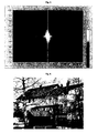
- Fig. 1 shows a blurred black and white recording, which should be corrected by the method according to the invention.
- Fig. 1 Fourier transformed image data in a first correction step and logarithmized in a second correction step to decouple image and noise component.
- Fig. 2 shows, with a Nyquist shift was made for better illustration.
- the direction of camera shake can be determined by the line pattern, which is easily visible in the picture.
- the direction of displacement of the image data is in fact perpendicular to the lines to be seen. Visible is this shake or shift, by the in Fig. 2 a re-Fourier transformation is performed.
- Fig. 3 The result of this third correction step is in Fig. 3 shown, where only the average image detail has been shown enlarged.
- This image again shows the multiply transformed image data in a spatial representation, but now the displacement or interference component and the image component are decoupled.
- the noise component is looped in the center of the picture, in each case at the coinciding corners of the quadrants.
- the coordinate axes themselves represent the image information which belongs to the highest amplitude frequencies in the original image data.
- the task of the further procedure is now, the disturbance part of in Fig. 3 in the center loop-shaped light appears to eliminate, without thereby falsifying the image data, which are located on the coordinate axes but also in the background of the entire representation, too strong.
- the correction component can consist of, for example, an average over the data of the quadrant with a noise component. An example of this is in Fig. 4 shown.
Landscapes
- Engineering & Computer Science (AREA)
- Physics & Mathematics (AREA)
- General Physics & Mathematics (AREA)
- Theoretical Computer Science (AREA)
- Multimedia (AREA)
- Signal Processing (AREA)
- Image Processing (AREA)
- Image Analysis (AREA)
Abstract
Description
Die Erfindung betrifft ein Verfahren zum Verarbeiten digitaler Bilddaten von mit einer fotografischen Kamera erfassten Bildern.The invention relates to a method for processing digital image data of images captured with a photographic camera.
Bei der Aufnahme von Fotografien kommt es insbesondere bei längeren Belichtungszeiten oftmals dazu, dass der Fotograf die Kamera nicht ruhig halten kann oder das Motiv sich während der Belichtung bewegt, so dass die Aufnahme verwackelt. Das aufgenommene Bild erscheint dann unscharf, das Motiv ist oftmals nur schwer zu erkennen. Da diese Bilder im Allgemeinen als Ausschuss betrachtet werden, ist es nicht gewünscht, von diesen Bildern Abzüge zu machen. Dennoch gelangen diese Bilder über einzuscannende Filme oder direkt von der Digitalkamera ins Fotolabor, wo automatisch von den Bildern Abzüge erstellt werden, denn der Fotograf ist auch bei digitalen Kameras oftmals nicht in der Lage auf den kleinen, niedrig aufgelösten Displays zu erkennen, dass die Aufnahme unscharf ist.When taking photographs, it is often the case that the photographer is unable to hold the camera steady or the subject moves during the exposure, especially during longer exposure times, so that the picture shimmers. The recorded image then appears blurred, the subject is often difficult to recognize. Since these images are generally considered scrap, it is not desirable to make prints from these images. Nevertheless, these images get scanned movies or directly from the digital camera in the photo lab, where automatically deducted from the images are created, because the photographer is often not able to recognize even with digital cameras on the small, low-resolution displays that the recording is out of focus.
So wurden bereits für analoge Kopiergeräte in Fotolaboren Verfahren entwickelt, welche unscharfe Bilder erkennen. Ein Beispiel hierfür ist in der
Daher wurden Verfahren entwickelt derartige verwackelte Aufnahmen zu korrigieren. So beschreibt bspw. die
In der
In der
Aufgabe der Erfindung war es deshalb, ein Verfahren zu entwickeln, bei dem wenigstens ein Teil der unscharfen Aufnahmen im Nachhinein möglichst gut korrigiert werden kann.The object of the invention was therefore to develop a method in which at least some of the blurred images can be corrected as well as possible afterwards.
Erfindungsgemäß werden diejenigen unter den unscharfen Aufnahmen gesucht, deren Unschärfe vom Verwackeln, also von einer Relativbewegung von Kamera und Motiv während der Belichtung verursacht wurde. Überraschenderweise konnte gezeigt werden, dass diese verwackelten Aufnahmen durch gezielte Korrekturmaßnahmen soweit restauriert werden können, dass akzeptable Aufnahmen entstehen, welche auf ein Wiedergabe- oder Speichermedium ausgegeben wer den können. Damit werden nicht mehr alle unscharfen Aufnahmen einfach als unbrauchbar verworfen, sondern ein Teil derselben wird geschickt soweit modifiziert, dass sich ein akzeptables Bild ergibt. Die Ausschussrate der Bilder wird also deutlich geringer, der Fotograf erhält mehr Abzüge seiner oftmals unwiederbringlichen Aufnahmen. Gerade bei einmaligen Aufnahmen kann dieses Verfahren große Vorteile bringen, da es zwar nicht unbedingt zu einem perfekten Bild führt, die Aufnahme aber soweit verbessert wird, dass das Motiv sehr gut zu erkennen ist und das Bild gern vom Fotografen als Erinnerung aufgehoben wird.According to the invention those are sought among the blurred images whose blurring was caused by shaking, ie by a relative movement of the camera and subject during the exposure. Surprisingly, it could be shown that these blurred images can be restored by targeted corrective measures to the extent that acceptable recordings arise, which is spent on a playback or storage medium you can. Thus, not all blurred images are simply discarded as unusable, but a part of them is cleverly modified so far that results in an acceptable picture. The reject rate of images is thus significantly lower, the photographer receives more prints of his often irretrievable shots. Especially with one-time shots, this method can bring great benefits, since it does not necessarily lead to a perfect picture, but the recording is improved so much that the subject is very easy to recognize and the image is like picked up by the photographer as a reminder.
Verwackelte Aufnahmen werden identifiziert, indem die Bilddaten entlang wenigstens zweier ihrer Dimensionen, also z. B. in x- und y-Richtung auf ihre Schärfe hin untersucht werden. Durch die Relativbewegung, welche während der Aufnahme stattgefunden hat, kommt es nämlich in den wiedergegebenen Bilddaten zu einer gerichteten Unschärfe. Die Unschärfe besteht in Richtung der Relativbewegung, entlang anderer Richtungen, insbesondere senkrecht dazu, können die Bilddaten dagegen scharf sein. Verwackelte Aufnahmen sind also dadurch gekennzeichnet, dass sie entlang verschiedener Richtungen im Bild einen unterschiedlichen Schärfegrad aufweisen. Während also unscharfe Aufnahmen dadurch erkannt werden, dass entlang aller zu untersuchenden Richtungen im Bild keine scharfen Strukturen zu finden sind, werden verwackelte Aufnahmen daran erkannt, dass sie zwar entlang einer Richtung unscharf sind, entlang einer anderen, im Wesentlichen dazu senkrechten Richtung, scharf sind. Auch wenn dieser theoretische Idealfall nicht immer vorliegt, kann man zumindest davon ausgehen, dass ihr Schärfegrad entlang unterschiedlicher Bildrichtungen unterschiedlich ist. Obwohl es vorteilhaft ist, müssen die zu untersuchenden Richtungen nicht unbedingt senkrecht aufeinander stehen. Es könnte sich auch beispielsweise um eine Parallele zu einer Bildseite und die Bilddiagonale handeln, welche untersucht werden.Shaky images are identified by the image data along at least two of their dimensions, so z. B. in the x and y directions are examined for their sharpness out. Due to the relative movement which took place during the recording, a directed blurring occurs in the reproduced image data. The blur consists in the direction of the relative movement, along other directions, in particular perpendicular thereto, the image data, however, can be sharp. Shaky shots are thus characterized by having different degrees of sharpness along different directions in the image. So while blurred images are detected by the fact that no sharp structures can be found along all directions to be examined in the image, shaky images are on it recognized that they are blurred along one direction, along another, substantially perpendicular direction, are sharp. Even if this ideal theoretical case is not always available, it can at least be assumed that its degree of severity differs along different image directions. Although it is advantageous, the directions to be examined need not necessarily be perpendicular to each other. It could also be, for example, a parallel to an image page and the image diagonal, which are examined.
Um verwackelte Aufnahmen zu identifizieren, können alle zu bearbeitenden Aufnahmen untersucht werden. Um Rechenzeit einzusparen ist es allerdings oftmals sinnvoller, die verwackelten Aufnahmen nur unter den Aufnahmen zu suchen, welche bereits als unscharf detektiert wurden.To identify shaky recordings, all recordings to be edited can be examined. In order to save computing time, however, it often makes more sense to search the shaky recordings only among the recordings that were already detected as out of focus.
Um die Schärfe einer Aufnahme entlang einer Richtung zu untersuchen, können beispielsweise scharfe Übergänge, also Kanten in den Bilddaten gesucht werden. Bei unscharfen Aufnahmen treten nämlich keine derartigen Kanten auf, da hier die Dichtesprünge verwaschen sind. Derartige Kantendetektionsverfahren sind beispielsweise aus der Bilddatenverschärfung bekannt. Eines dieser Verfahren ist in der
Um sicherer feststellen zu können, ob es sich um eine verwackelte oder eine unscharfe Aufnahme handelt, ist es wünschenswert, nicht nur entlang zweier Richtungen zu untersuchen, sondern entlang dreier Richtungen. Hier können sich beispielsweise die Koordinatenachsen und die Bilddiagonale anbieten.In order to more reliably determine whether it is a blurred or a blurry image, it is desirable to study not only along two directions, but along three directions. Here, for example, the coordinate axes and the image diagonal can offer.
Um die als verwackelt identifizierten Aufnahmen zu korrigieren wird eine Fouriertransformation der Bilddaten vorgenommen.In order to correct the images identified as blurred, a Fourier transformation of the image data is performed.
Dabei werden die Bilddaten vom Orts- in den Frequenzraum transferiert. Im Frequenzraum kann dann die das Bildmotiv störende Frequenz ermittelt werden, welche durch die Relativbewegung bei der Aufnahme dem Bildmotiv überlagert wurde. Die erfindungsgemäße Korrektur zielt nun darauf ab, diesen Störanteil vom eigentlichen aufgenommenen Bildanteil zu trennen, so dass dieser Störanteil durch einen Korrekturanteil ersetzt werden kann, was auch ein einfaches Eliminieren des Störanteils umfasst, so dass anschließend der ursprünglich gewünschte Bildanteil und der Korrekturanteil wiederum zusammengefasst werden können, woraus sich der korrigierte Bildinhalt ergibt, welcher eine vergleichsweise ungestörte Darstellung des aufzunehmenden Bildmotivs umfasst.The image data is transferred from local to frequency space. In the frequency space, the image motif disturbing frequency can then be determined, which was superimposed by the relative movement during recording the image motif. The correction according to the invention now aims to separate this noise component from the actual recorded image component, so that this noise component can be replaced by a correction component, which also includes a simple elimination of the interference component, so that subsequently the originally desired image component and the correction component are combined again can, from which the corrected image content results, which comprises a comparatively undisturbed representation of the image motif to be recorded.
Um Bildanteil und Störanteil der Bilddaten zu entkoppeln wird die Fouriertransformierte logarithmiert. Hierdurch erreicht man eine Umwandlung in eine Summe der Anteile, so dass der Störanteil der Bilddaten getrennt vom eigentlich gewünschten Bildmotiv, also den Bildanteil, vorliegt. Es gibt jedoch auch weitere Möglichkeiten zur Entkopplung von Stör- und Bildanteil. Um dieses Korrekturverfahren etwas transparenter zu erläutern, werden im Folgenden die mathematischen Entsprechungen der beschriebenen Schritte dargestellt.In order to decouple the image component and the noise component of the image data, the Fourier transform is logarithmized. This achieves a conversion into a sum of the shares, so that the noise component of the image data is separate from the actually desired image motif, ie the image portion. However, there are also other possibilities for decoupling of interference and image component. In order to explain this correction process somewhat more transparently, the mathematical equivalents of the described steps are shown below.
Das verwackelte Bild f'(x,y) lässt sich an jedem Bildpunkt (x,y) darstellen als 
also als Summe der mehrmals um verschiedene Faktoren verschobenen selben Bildinformation.The blurred image f '( x , y ) can be represented at each pixel ( x , y ) as
that is, the sum of the same image information several times shifted by different factors.
Durch eine Fouriertransformation ergibt sich daraus die Fouriertransformierte des verwackelten Bildes 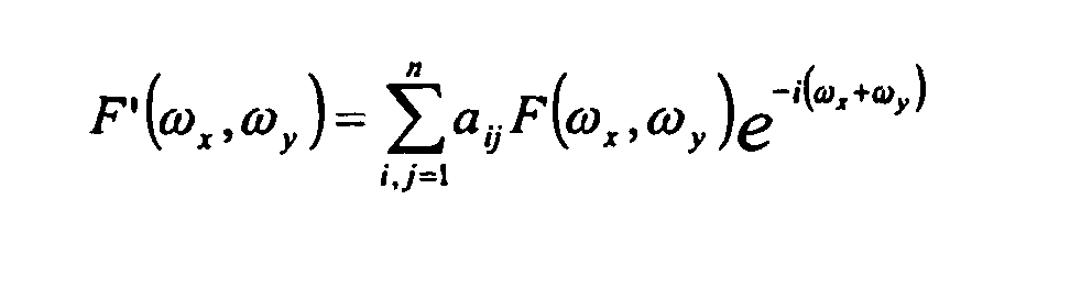

also eine Faltung aus "reinem" Bildanteil F(ω x ,ω y ) und einem Störanteil S(ω x ,ω y ).A Fourier transformation results in the Fourier transform of the blurred image
ie a convolution of "pure" image component F (ω x , ω y ) and a noise component S (ω x , ω y ).
Eine Möglichkeit, beide Anteile zu trennen besteht nun in einer Quotientenbildung. Dabei ergibt sich der Bildanteil durch 
Dieses Verfahren ist zwar prinzipiell anwendbar, man müsste jedoch die Problematik der Division durch Null vermeiden.Although this method is applicable in principle, one would have to avoid the problem of dividing by zero.
Ein vorteilhafteres Verfahren zur Entkopplung von Stör- und Bildanteil besteht deshalb in einer Logarithmierung der Fouriertransformierten, wobei sich ![]()
oder ![]()
also eine Summe aus Bild- und Störanteil ergibt.A more advantageous method for decoupling interference and image component therefore consists in logarithmizing the Fourier transform, wherein ![]()
or ![]()
So a sum of image and noise component results.
Nach erneuter Fouriertransformation folgt daraus 
Nun kann der Störanteil s1 (Δ x ,Δ y ), welcher vom Bildanteil entkoppelt und auf einen definierten räumlichen Bereich beschränkt ist, durch einen Korrekturanteil ersetzt werden. Im Einzelnen wird dies anhand der Figurenbeschreibung erläutert.Now, the interference component s 1 (Δ x , Δ y ), which is decoupled from the image component and limited to a defined spatial region, can be replaced by a correction component. This is explained in detail with reference to the description of the figures.
Durch folgende Fourier-Rück-Transformationen und Anwendung der Exponentialfunktion wird diese korrigierte Funktion schließlich in korrigierte Bilddaten rückverwandelt.By following Fourier-back transformations and applying the exponential function, this corrected function is finally reconverted into corrected image data.
Vorteilhafterweise werden die als verwackelt identifizierten Aufnahmen bei der Ausgabe der digitalen Bilder als verwackelt gekennzeichnet. Dadurch kann der Kunde erkennen, dass das Bildmotiv zwar nicht optimal erfasst wurde, mittels der Bildbearbeitung aber versucht wurde, ein akzeptables Bild daraus zu gestalten. Um dem Kunden einen Vergleich zwischen seiner ursprünglichen Aufnahme und dem korrigierten Bild zu ermöglichen, ist es weiterhin vorteilhaft, sowohl die ursprüngliche, verwackelte Aufnahme als auch die korrigierten Bilddaten auszugeben. Dies muss zwar nicht in Form von zwei tatsächlichen Ausdrucken erfolgen, sinnvoller ist es, wenn beide Datensätze digital zur Verfügung gestellt werden.Advantageously, the images identified as blurred are marked blurred in the output of the digital images. As a result, the customer can recognize that the image motif was not captured optimally, but the image processing was attempted to create an acceptable image from it. In order to allow the customer a comparison between its original image and the corrected image, it is also advantageous to output both the original blurred image and the corrected image data. Although this does not have to be done in the form of two actual printouts, it makes more sense if both datasets are made available digitally.
Die Kennzeichnung der verwackelten Aufnahmen kann vorteilhafterweise auf dem Indexprint vorgenommen werden.The labeling of blurred images can be advantageously made on the Indexprint.
Weiterhin ist es vorteilhaft, die verwackelten, korrigierten Aufnahmen gesondert auszugeben. Diese gesonderte Ausgabe ermöglicht es dem Finisher, sie nochmal zu überprüfen, um zu sehen, ob man diese Aufnahme nun tatsächlich an den Kunden verkaufen kann oder ob die Bildqualität weiterhin auch nach der Korrektur so schlecht ist, dass sie als Ausschuss zu behandeln ist.Furthermore, it is advantageous to output the blurred, corrected images separately. This separate edition allows the finisher to re-check them to see if they can actually sell that shot to the customer, or if the image quality continues to be so bad after the fix that it's considered scrap.
Weitere Merkmale und Vorteile der Erfindung ergeben sich aus der folgenden Beschreibung bevorzugter Ausführungsformen und Anwendungsbeispiele, wobei Bezug auf die beigefügten Zeichnungen genommen wird.Further features and advantages of the invention will become apparent from the following description of preferred embodiments and application examples, reference being made to the accompanying drawings.
Es zeigen:
- Fig. 1
- verwackeltes Originalbild,
- Fig. 2
- logarithmierte Fouriertransformierte des Originalbildes,
- Fig. 3
- Ausschnitt der erneuten Fouriertransformierten, bei der der Störanteil sichtbar wird,
- Fig. 4
- entspricht
Fig. 3 , jedoch ist der Störanteil durch einen Korrekturanteil ersetzt, - Fig. 5
- rücktransformiertes, korrigiertes Bild im Fourierraum und
- Fig. 6
- korrigiertes Bild.
- Fig. 1
- blurred original image,
- Fig. 2
- logarithmized Fourier transform of the original image,
- Fig. 3
- Section of the re-Fourier transform, where the noise component becomes visible,
- Fig. 4
- corresponds to
Fig. 3 but the noise component is replaced by a correction component, - Fig. 5
- Inverted, corrected image in Fourier space and
- Fig. 6
- corrected picture.
Claims (12)
- Method for digital data processing of images, photos of image patterns taken with a camera, comprising the following stages:- detection of fuzzy photos, caused by a relative movement between the image pattern to take and the camera used to take the said pattern,- fuzzy photos corrections and- corrected photos output on a storage medium,characterized in transforming, for photos correction, the image part to keep and the perturbation part, caused by the camera movement in relation to the image pattern to take, thanks to the Fourier transform logarithm calculation of the image data, into a sum, in uncoupling this way the said parts, in determining, thanks to a new Fourier transform logarithm calculation, the perturbation part, in the replacement of the determined perturbation part by a correction part, and in that the image part and the correction part are joined together and retransformed in corrected image data.
- Method according to claim 1, characterized in that is analyzed, for the determination of the fuzzy photos, caused by the camera movement in relation to the image pattern to take, the image data along at least two directions of the plan x - y inside the fuzzy photo caused by the camera movement in relation to the image pattern to be taken.
- Method according to claim 2, characterized in that the image data is analyzed along three directions inside the plan x-y.
- Method according to claims 2 or 3, characterized in that density steps inside the image data are determined along the analysis directions.
- Method according to claim 4, characterized in that the image data along an analysis direction are qualified as sharp if they have a minimal number of density steps.
- Method according to claims 1 or 2, characterized in that the image data are qualified as fuzzy, because of the camera movement in relation to the image pattern to take, if they are identified as fuzzy in at least one of the directions to analyze, and as sharp in at least one other direction.
- Method according to claim 1, characterized in that, for the determination of the correction parts, corresponding image data areas inside the quadrants of the image data, transformed thanks to a Fourier transform of the Fourier transforms obtained by logarithm calculation, are compared one with each other.
- Method according to claim 7, characterized in that the correction is done by adapting the perturbed areas inside the quadrants of the transformed image data to corresponding image data areas inside quadrants without perturbation.
- Method according to claim 8, characterized in that the transformed image data, which belong to the frequencies with the biggest amplitudes, are not modified.
- Method according to claim 1, characterized in that fuzzy photos caused by the camera movement in relation to the image pattern to take are labelled during the output.
- Method according to claim 10, characterized in that fuzzy photos caused by the camera movement in relation to the image pattern to take are labelled on an indexprint.
- Method according to claim 1, characterized in that fuzzy photos caused by the camera movement in relation to the image pattern to take, and other photos, are separately outputted.
Priority Applications (2)
| Application Number | Priority Date | Filing Date | Title |
|---|---|---|---|
| EP03029392A EP1548645B1 (en) | 2003-12-19 | 2003-12-19 | Method of processing digital image data from motion blurred exposures |
| DE50309706T DE50309706D1 (en) | 2003-12-19 | 2003-12-19 | Method of processing digital image data from blurred photographs |
Applications Claiming Priority (1)
| Application Number | Priority Date | Filing Date | Title |
|---|---|---|---|
| EP03029392A EP1548645B1 (en) | 2003-12-19 | 2003-12-19 | Method of processing digital image data from motion blurred exposures |
Publications (2)
| Publication Number | Publication Date |
|---|---|
| EP1548645A1 EP1548645A1 (en) | 2005-06-29 |
| EP1548645B1 true EP1548645B1 (en) | 2008-04-23 |
Family
ID=34530681
Family Applications (1)
| Application Number | Title | Priority Date | Filing Date |
|---|---|---|---|
| EP03029392A Expired - Lifetime EP1548645B1 (en) | 2003-12-19 | 2003-12-19 | Method of processing digital image data from motion blurred exposures |
Country Status (2)
| Country | Link |
|---|---|
| EP (1) | EP1548645B1 (en) |
| DE (1) | DE50309706D1 (en) |
Families Citing this family (1)
| Publication number | Priority date | Publication date | Assignee | Title |
|---|---|---|---|---|
| JP5657375B2 (en) * | 2010-12-24 | 2015-01-21 | オリンパス株式会社 | Endoscope apparatus and program |
Family Cites Families (6)
| Publication number | Priority date | Publication date | Assignee | Title |
|---|---|---|---|---|
| US3947109A (en) * | 1974-08-08 | 1976-03-30 | Kinder Claude E | Apparatus and method for processing photographic paper strip |
| US5111515A (en) * | 1990-06-29 | 1992-05-05 | The United States Of America As Represented By The Secretary Of The Air Force | Image deconvolution by a logarithmic exponential nonlinear joint transform process |
| US5365303A (en) * | 1992-05-21 | 1994-11-15 | Olympus Optical Co., Ltd. | Shake-free image restoration system |
| JPH11284944A (en) * | 1998-03-31 | 1999-10-15 | Canon Inc | Image processing method and system |
| US7176962B2 (en) * | 2001-03-01 | 2007-02-13 | Nikon Corporation | Digital camera and digital processing system for correcting motion blur using spatial frequency |
| US6987530B2 (en) * | 2001-05-29 | 2006-01-17 | Hewlett-Packard Development Company, L.P. | Method for reducing motion blur in a digital image |
-
2003
- 2003-12-19 EP EP03029392A patent/EP1548645B1/en not_active Expired - Lifetime
- 2003-12-19 DE DE50309706T patent/DE50309706D1/en not_active Expired - Fee Related
Also Published As
| Publication number | Publication date |
|---|---|
| DE50309706D1 (en) | 2008-06-05 |
| EP1548645A1 (en) | 2005-06-29 |
Similar Documents
| Publication | Publication Date | Title |
|---|---|---|
| DE69628723T2 (en) | Gradient-based method for generating values for unknown pixels in a digital image | |
| DE69432239T2 (en) | Field detection | |
| DE102012204019B4 (en) | Method for reducing motion artifacts | |
| DE3546135C2 (en) | ||
| DE69733978T2 (en) | image data interpolating | |
| DE19530829C2 (en) | Method for electronically retrieving information added to a document | |
| DE60012649T2 (en) | ELIMINATION OF CHROMUSES FROM DIGITAL PICTURES BY USING VARIABLE SHAPED PIXEL LIBRARY AREAS | |
| DE60309979T2 (en) | Method and apparatus for correcting image data obtained from an original image which is affected by edge drop of the light | |
| DE112017006107T5 (en) | Digital correction of optical system aberrations | |
| WO2007051566A2 (en) | Method and device for reconstructing images | |
| DE112009002658T5 (en) | Method and apparatus for video noise reduction | |
| DE102007013570A1 (en) | Method for noise reduction in digital images with locally different and directional noise | |
| EP1865461A2 (en) | Method of digital gray-level image processing | |
| DE2652287C3 (en) | Method and device for determining the sharpness of an image | |
| EP1251464A2 (en) | Method for retouching re-scanned raster binary images | |
| DE112017006779T5 (en) | CAMERA SYSTEM INCLUDING OBJECTIVE WITH MAGNIFICATION GRADIENT | |
| DE102007058498A1 (en) | Method and apparatus for noise reduction in medical images | |
| EP3656561A1 (en) | Fast image restoration for image inspection | |
| DE69724200T2 (en) | Method and device for generating a digital image representation | |
| EP1548645B1 (en) | Method of processing digital image data from motion blurred exposures | |
| DE10219919A1 (en) | Medical image quality improvement method for use with magnetic resonance and computer tomography, whereby a weighting factor is applied to each pixel based on the surrounding local color intensities and differences | |
| EP2054853B1 (en) | Apparatus and method for reducing transition artefacts in an overall image composed of partial images | |
| DE2408704C3 (en) | Electronic engraving and recording system | |
| DE4105517C2 (en) | Method and device for improved reproduction of contours | |
| WO2018224444A1 (en) | Method and device for image correction |
Legal Events
| Date | Code | Title | Description |
|---|---|---|---|
| PUAI | Public reference made under article 153(3) epc to a published international application that has entered the european phase |
Free format text: ORIGINAL CODE: 0009012 |
|
| AK | Designated contracting states |
Kind code of ref document: A1 Designated state(s): AT BE BG CH CY CZ DE DK EE ES FI FR GB GR HU IE IT LI LU MC NL PT RO SE SI SK TR |
|
| AX | Request for extension of the european patent |
Extension state: AL LT LV MK |
|
| AKX | Designation fees paid | ||
| 17P | Request for examination filed |
Effective date: 20060215 |
|
| RBV | Designated contracting states (corrected) |
Designated state(s): AT BE BG CH CY CZ DE DK EE ES FI FR GB GR HU IE IT LI LU MC NL PT RO SE SI SK TR |
|
| 19U | Interruption of proceedings before grant |
Effective date: 20060101 |
|
| 19W | Proceedings resumed before grant after interruption of proceedings |
Effective date: 20070502 |
|
| RBV | Designated contracting states (corrected) |
Designated state(s): CH DE FR GB IT LI |
|
| RAP1 | Party data changed (applicant data changed or rights of an application transferred) |
Owner name: IMAGING SOLUTIONS AG |
|
| GRAP | Despatch of communication of intention to grant a patent |
Free format text: ORIGINAL CODE: EPIDOSNIGR1 |
|
| GRAC | Information related to communication of intention to grant a patent modified |
Free format text: ORIGINAL CODE: EPIDOSCIGR1 |
|
| GRAS | Grant fee paid |
Free format text: ORIGINAL CODE: EPIDOSNIGR3 |
|
| GRAA | (expected) grant |
Free format text: ORIGINAL CODE: 0009210 |
|
| AK | Designated contracting states |
Kind code of ref document: B1 Designated state(s): CH DE FR GB IT LI |
|
| REG | Reference to a national code |
Ref country code: GB Ref legal event code: FG4D Free format text: NOT ENGLISH |
|
| REG | Reference to a national code |
Ref country code: CH Ref legal event code: EP |
|
| REF | Corresponds to: |
Ref document number: 50309706 Country of ref document: DE Date of ref document: 20080605 Kind code of ref document: P |
|
| ET | Fr: translation filed | ||
| PGFP | Annual fee paid to national office [announced via postgrant information from national office to epo] |
Ref country code: CH Payment date: 20081215 Year of fee payment: 6 |
|
| PLBE | No opposition filed within time limit |
Free format text: ORIGINAL CODE: 0009261 |
|
| STAA | Information on the status of an ep patent application or granted ep patent |
Free format text: STATUS: NO OPPOSITION FILED WITHIN TIME LIMIT |
|
| PGFP | Annual fee paid to national office [announced via postgrant information from national office to epo] |
Ref country code: IT Payment date: 20081222 Year of fee payment: 6 |
|
| 26N | No opposition filed |
Effective date: 20090126 |
|
| PGFP | Annual fee paid to national office [announced via postgrant information from national office to epo] |
Ref country code: FR Payment date: 20081212 Year of fee payment: 6 |
|
| PGFP | Annual fee paid to national office [announced via postgrant information from national office to epo] |
Ref country code: DE Payment date: 20081219 Year of fee payment: 6 |
|
| PGFP | Annual fee paid to national office [announced via postgrant information from national office to epo] |
Ref country code: GB Payment date: 20081216 Year of fee payment: 6 |
|
| REG | Reference to a national code |
Ref country code: CH Ref legal event code: PL |
|
| GBPC | Gb: european patent ceased through non-payment of renewal fee |
Effective date: 20091219 |
|
| REG | Reference to a national code |
Ref country code: FR Ref legal event code: ST Effective date: 20100831 |
|
| PG25 | Lapsed in a contracting state [announced via postgrant information from national office to epo] |
Ref country code: LI Free format text: LAPSE BECAUSE OF NON-PAYMENT OF DUE FEES Effective date: 20091231 Ref country code: FR Free format text: LAPSE BECAUSE OF NON-PAYMENT OF DUE FEES Effective date: 20091231 Ref country code: CH Free format text: LAPSE BECAUSE OF NON-PAYMENT OF DUE FEES Effective date: 20091231 |
|
| PG25 | Lapsed in a contracting state [announced via postgrant information from national office to epo] |
Ref country code: DE Free format text: LAPSE BECAUSE OF NON-PAYMENT OF DUE FEES Effective date: 20100701 |
|
| PG25 | Lapsed in a contracting state [announced via postgrant information from national office to epo] |
Ref country code: GB Free format text: LAPSE BECAUSE OF NON-PAYMENT OF DUE FEES Effective date: 20091219 |
|
| PG25 | Lapsed in a contracting state [announced via postgrant information from national office to epo] |
Ref country code: IT Free format text: LAPSE BECAUSE OF NON-PAYMENT OF DUE FEES Effective date: 20091219 |