EP1548447B1 - Method of producing analytical tool - Google Patents
Method of producing analytical tool Download PDFInfo
- Publication number
- EP1548447B1 EP1548447B1 EP03798514A EP03798514A EP1548447B1 EP 1548447 B1 EP1548447 B1 EP 1548447B1 EP 03798514 A EP03798514 A EP 03798514A EP 03798514 A EP03798514 A EP 03798514A EP 1548447 B1 EP1548447 B1 EP 1548447B1
- Authority
- EP
- European Patent Office
- Prior art keywords
- groove
- analytical tool
- substrate
- producing method
- modifying
- Prior art date
- Legal status (The legal status is an assumption and is not a legal conclusion. Google has not performed a legal analysis and makes no representation as to the accuracy of the status listed.)
- Expired - Lifetime
Links
- 238000000034 method Methods 0.000 title claims abstract description 38
- 239000000758 substrate Substances 0.000 claims abstract description 46
- 239000007788 liquid Substances 0.000 claims abstract description 18
- 239000002861 polymer material Substances 0.000 claims abstract description 9
- XLYOFNOQVPJJNP-UHFFFAOYSA-N water Substances O XLYOFNOQVPJJNP-UHFFFAOYSA-N 0.000 claims description 39
- 239000007789 gas Substances 0.000 claims description 33
- 229910052731 fluorine Inorganic materials 0.000 claims description 14
- MYMOFIZGZYHOMD-UHFFFAOYSA-N Dioxygen Chemical compound O=O MYMOFIZGZYHOMD-UHFFFAOYSA-N 0.000 claims description 8
- YCKRFDGAMUMZLT-UHFFFAOYSA-N Fluorine atom Chemical compound [F] YCKRFDGAMUMZLT-UHFFFAOYSA-N 0.000 claims description 8
- 229910001882 dioxygen Inorganic materials 0.000 claims description 8
- 239000011737 fluorine Substances 0.000 claims description 8
- 229920003229 poly(methyl methacrylate) Polymers 0.000 claims description 7
- 239000004926 polymethyl methacrylate Substances 0.000 claims description 7
- 125000001153 fluoro group Chemical group F* 0.000 claims description 6
- 229920000642 polymer Polymers 0.000 claims description 6
- 238000002156 mixing Methods 0.000 claims description 5
- 125000003178 carboxy group Chemical group [H]OC(*)=O 0.000 claims description 3
- 125000002887 hydroxy group Chemical group [H]O* 0.000 claims description 3
- 125000000468 ketone group Chemical group 0.000 claims description 3
- 238000005507 spraying Methods 0.000 claims description 2
- 239000003153 chemical reaction reagent Substances 0.000 description 15
- 238000006243 chemical reaction Methods 0.000 description 11
- 239000000853 adhesive Substances 0.000 description 9
- 230000001070 adhesive effect Effects 0.000 description 9
- 238000004519 manufacturing process Methods 0.000 description 8
- 239000004094 surface-active agent Substances 0.000 description 8
- 239000011347 resin Substances 0.000 description 7
- 229920005989 resin Polymers 0.000 description 7
- 239000012530 fluid Substances 0.000 description 5
- 239000011344 liquid material Substances 0.000 description 4
- 239000000463 material Substances 0.000 description 4
- 238000005259 measurement Methods 0.000 description 4
- 239000000126 substance Substances 0.000 description 4
- 230000003287 optical effect Effects 0.000 description 3
- 238000004080 punching Methods 0.000 description 3
- 238000004458 analytical method Methods 0.000 description 2
- 239000004205 dimethyl polysiloxane Substances 0.000 description 2
- 238000002848 electrochemical method Methods 0.000 description 2
- JEGUKCSWCFPDGT-UHFFFAOYSA-N h2o hydrate Chemical compound O.O JEGUKCSWCFPDGT-UHFFFAOYSA-N 0.000 description 2
- 238000001746 injection moulding Methods 0.000 description 2
- 229920000435 poly(dimethylsiloxane) Polymers 0.000 description 2
- -1 polydimethylsiloxane Polymers 0.000 description 2
- 239000005020 polyethylene terephthalate Substances 0.000 description 2
- 229920000139 polyethylene terephthalate Polymers 0.000 description 2
- 239000004793 Polystyrene Substances 0.000 description 1
- 230000001464 adherent effect Effects 0.000 description 1
- QVGXLLKOCUKJST-UHFFFAOYSA-N atomic oxygen Chemical compound [O] QVGXLLKOCUKJST-UHFFFAOYSA-N 0.000 description 1
- 239000007795 chemical reaction product Substances 0.000 description 1
- 239000003795 chemical substances by application Substances 0.000 description 1
- 239000011248 coating agent Substances 0.000 description 1
- 238000000576 coating method Methods 0.000 description 1
- 238000005520 cutting process Methods 0.000 description 1
- 230000007423 decrease Effects 0.000 description 1
- 238000007599 discharging Methods 0.000 description 1
- 238000001035 drying Methods 0.000 description 1
- 238000005530 etching Methods 0.000 description 1
- 229920001477 hydrophilic polymer Polymers 0.000 description 1
- 238000003754 machining Methods 0.000 description 1
- 238000000465 moulding Methods 0.000 description 1
- 230000003647 oxidation Effects 0.000 description 1
- 238000007254 oxidation reaction Methods 0.000 description 1
- 239000001301 oxygen Substances 0.000 description 1
- 229910052760 oxygen Inorganic materials 0.000 description 1
- 238000009832 plasma treatment Methods 0.000 description 1
- 239000004417 polycarbonate Substances 0.000 description 1
- 229920000515 polycarbonate Polymers 0.000 description 1
- 238000003825 pressing Methods 0.000 description 1
- 239000000047 product Substances 0.000 description 1
- 238000010926 purge Methods 0.000 description 1
- 238000005549 size reduction Methods 0.000 description 1
- 229920005992 thermoplastic resin Polymers 0.000 description 1
Images


Classifications
-
- G—PHYSICS
- G01—MEASURING; TESTING
- G01N—INVESTIGATING OR ANALYSING MATERIALS BY DETERMINING THEIR CHEMICAL OR PHYSICAL PROPERTIES
- G01N33/00—Investigating or analysing materials by specific methods not covered by groups G01N1/00 - G01N31/00
- G01N33/48—Biological material, e.g. blood, urine; Haemocytometers
- G01N33/50—Chemical analysis of biological material, e.g. blood, urine; Testing involving biospecific ligand binding methods; Immunological testing
- G01N33/53—Immunoassay; Biospecific binding assay; Materials therefor
- G01N33/543—Immunoassay; Biospecific binding assay; Materials therefor with an insoluble carrier for immobilising immunochemicals
- G01N33/54393—Improving reaction conditions or stability, e.g. by coating or irradiation of surface, by reduction of non-specific binding, by promotion of specific binding
-
- B—PERFORMING OPERATIONS; TRANSPORTING
- B01—PHYSICAL OR CHEMICAL PROCESSES OR APPARATUS IN GENERAL
- B01L—CHEMICAL OR PHYSICAL LABORATORY APPARATUS FOR GENERAL USE
- B01L3/00—Containers or dishes for laboratory use, e.g. laboratory glassware; Droppers
- B01L3/50—Containers for the purpose of retaining a material to be analysed, e.g. test tubes
- B01L3/502—Containers for the purpose of retaining a material to be analysed, e.g. test tubes with fluid transport, e.g. in multi-compartment structures
- B01L3/5027—Containers for the purpose of retaining a material to be analysed, e.g. test tubes with fluid transport, e.g. in multi-compartment structures by integrated microfluidic structures, i.e. dimensions of channels and chambers are such that surface tension forces are important, e.g. lab-on-a-chip
- B01L3/502707—Containers for the purpose of retaining a material to be analysed, e.g. test tubes with fluid transport, e.g. in multi-compartment structures by integrated microfluidic structures, i.e. dimensions of channels and chambers are such that surface tension forces are important, e.g. lab-on-a-chip characterised by the manufacture of the container or its components
-
- C—CHEMISTRY; METALLURGY
- C08—ORGANIC MACROMOLECULAR COMPOUNDS; THEIR PREPARATION OR CHEMICAL WORKING-UP; COMPOSITIONS BASED THEREON
- C08J—WORKING-UP; GENERAL PROCESSES OF COMPOUNDING; AFTER-TREATMENT NOT COVERED BY SUBCLASSES C08B, C08C, C08F, C08G or C08H
- C08J7/00—Chemical treatment or coating of shaped articles made of macromolecular substances
- C08J7/12—Chemical modification
-
- G—PHYSICS
- G01—MEASURING; TESTING
- G01N—INVESTIGATING OR ANALYSING MATERIALS BY DETERMINING THEIR CHEMICAL OR PHYSICAL PROPERTIES
- G01N27/00—Investigating or analysing materials by the use of electric, electrochemical, or magnetic means
- G01N27/26—Investigating or analysing materials by the use of electric, electrochemical, or magnetic means by investigating electrochemical variables; by using electrolysis or electrophoresis
- G01N27/416—Systems
- G01N27/447—Systems using electrophoresis
- G01N27/44704—Details; Accessories
- G01N27/44752—Controlling the zeta potential, e.g. by wall coatings
-
- B—PERFORMING OPERATIONS; TRANSPORTING
- B01—PHYSICAL OR CHEMICAL PROCESSES OR APPARATUS IN GENERAL
- B01L—CHEMICAL OR PHYSICAL LABORATORY APPARATUS FOR GENERAL USE
- B01L2200/00—Solutions for specific problems relating to chemical or physical laboratory apparatus
- B01L2200/12—Specific details about manufacturing devices
-
- B—PERFORMING OPERATIONS; TRANSPORTING
- B01—PHYSICAL OR CHEMICAL PROCESSES OR APPARATUS IN GENERAL
- B01L—CHEMICAL OR PHYSICAL LABORATORY APPARATUS FOR GENERAL USE
- B01L2300/00—Additional constructional details
- B01L2300/08—Geometry, shape and general structure
- B01L2300/0809—Geometry, shape and general structure rectangular shaped
- B01L2300/0816—Cards, e.g. flat sample carriers usually with flow in two horizontal directions
-
- B—PERFORMING OPERATIONS; TRANSPORTING
- B01—PHYSICAL OR CHEMICAL PROCESSES OR APPARATUS IN GENERAL
- B01L—CHEMICAL OR PHYSICAL LABORATORY APPARATUS FOR GENERAL USE
- B01L2300/00—Additional constructional details
- B01L2300/08—Geometry, shape and general structure
- B01L2300/0861—Configuration of multiple channels and/or chambers in a single devices
- B01L2300/0867—Multiple inlets and one sample wells, e.g. mixing, dilution
-
- B—PERFORMING OPERATIONS; TRANSPORTING
- B01—PHYSICAL OR CHEMICAL PROCESSES OR APPARATUS IN GENERAL
- B01L—CHEMICAL OR PHYSICAL LABORATORY APPARATUS FOR GENERAL USE
- B01L2300/00—Additional constructional details
- B01L2300/08—Geometry, shape and general structure
- B01L2300/0887—Laminated structure
-
- B—PERFORMING OPERATIONS; TRANSPORTING
- B01—PHYSICAL OR CHEMICAL PROCESSES OR APPARATUS IN GENERAL
- B01L—CHEMICAL OR PHYSICAL LABORATORY APPARATUS FOR GENERAL USE
- B01L2300/00—Additional constructional details
- B01L2300/16—Surface properties and coatings
- B01L2300/161—Control and use of surface tension forces, e.g. hydrophobic, hydrophilic
Definitions
- the present invention relates to a method of producing an analytical tool which is used for analyzing a sample liquid and which is structured to move the sample liquid before the analysis.
- a sample liquid is caused to move by capillary action.
- Such an analytical tool includes a capillary for producing a capillary force.
- the inner surface of the capillary is hydrophilically treated.
- a capillary 93 is formed by covering a groove 91 formed in a substrate 90 with a cover 92.
- the bottom surface 91a of the groove 91 and one surface 92a of the cover 92 are hydrophilically treated.
- the hydrophilization treatment with respect to the inner surface of the capillary 93 may be performed by ultraviolet irradiation, the application of a surface-active agent or plasma discharge such as glow discharge or corona discharge, for example. (See JP-A 2001-159618 and JP-A 2002-168821 , for example.)
- the proportion of the hydrophilically-treated surfaces decreases in the case where hydrophilization treatment is performed only with respect to the bottom surface 91a of each groove 91 and to one surface 92a of the cover 92. Therefore, to properly move the sample liquid through the capillary 93, the hydrophilization treatment need be performed also with respect to the side surfaces 91b of the groove 91.
- the hydrophilization treatment by the application of a surface-active agent is performed by supplying a liquid material containing a surface-active agent into the groove 91 and then drying the liquid material. Therefore, to apply the surface-active agent to the side surfaces 91b of the groove 91, it is necessary to completely fill the groove 91 with the liquid material and then dry the liquid material, as shown in Fig. 11B . In this way, since the groove 91 is filled with the surface-active agent to apply the surface-active agent to the side surface of the groove 91, the provision of a flow path having an intended sectional area is difficult.
- Hydrophilization of microchannel structures in the surface of a planar substrate (polymethyl methacrylate) by oxygen plasma treatment or by an oxidation agent and subsequent coating with a hydrophylic non-ionic hydrophilic polymer is described in WO01/47637 .
- the hydrophilization treatment by utilizing plasma discharge requires equipment for causing plasma discharge and hence requires high cost of equipment and manufacturing cost. Further, similarly to the hydrophilization treatment by ultraviolet irradiation, it is difficult to hydrophilically treat the side surfaces 91b of the groove 91 satisfactorily by plasma discharge.
- An object of the present invention is to provide a method which is capable of properly performing hydrophilization even with respect to a small flow path without increasing the cost.
- an analytical tool which comprises a substrate made of a polymer material and formed with a groove for moving a sample liquid, and a cover bonded to the substrate to cover the groove.
- the method comprises hydrophilically treating an inner surface of the groove, characterized in that the substrate is made of polymethyl methacrylate.
- the hydrophilization treatment includes a primary modifying step for primarily modifying characteristics of the inner surface of the groove by bringing a modifying gas which contains fluorine gas and oxygen gas into contact with the inner surface of the groove to introduce a fluorine atom to a side chain or an end group as bonded to a ketone group in a polymer chain of said substrate, and a secondary modifying step for secondarily modifying the characteristics of the inner surface of the groove by replacing the fluorine atom previously introduced with a hydroxyl group such that a carboxyl group, which is a hydrophilic group, is introduced into a polymer chain existing at a surface of the substrate.
- the degree of hydrophilization is such that the contact angle of pure water at the inner surface of the groove becomes 0-80 degrees, and preferably 0-60 degrees for example.
- the hydrophilization treatment may be performed before the cover is bonded to the substrate or after the cover is bonded to the substrate. In the latter case, when the cover is made of a polymer material, not only the inner surface of the groove but also the surface of the cover which faces the groove can be hydrophilically treated.
- the primary modifying step may be performed for 1-60 minutes under such conditions that the partial pressure of the modifying gas is maintained at 10-2000 hPa and temperature is maintained at 0-100°C, and preferably, the partial pressure of the modifying gas is maintained at 100-1100 hPa and temperature is maintained at 0-40 °C.
- the mixing ratio of the fluorine gas and the oxygen gas is 1:1-1000 on a volume basis.
- the secondary modifying step comprises bringing water or water vapor into contact with the inner surface of the groove.
- the bringing of water or water vapor into contact with the inner surface of the groove may comprise spraying water or water vapor to an inner surface of the substrate or immersing the substrate in a water bath.
- the substrate may be brought into contact with air for secondarily modifying the inner surface of the groove by the moisture contained in the air. In this case, use may be made of air which has been positively caused to contain moisture.
- the present invention is applicable to an analytical tool in which a sample liquid is caused to move by capillary action as a technique for making the inner surface of the fluid path hydrophilic.
- the present invention is applicable to such an analytical tool as a microdevice which includes a small fluidpath.
- the present invention is applicable to a microdevice which includes a fluid path having a principal cross section (corresponding to the principal cross section of the groove of the substrate) having a rectangular shape which has a width W of 10 ⁇ 500 ⁇ m and a depth D of 5-500 ⁇ m and satisfies D/W ⁇ 0.5.
- the principal cross section" herein indicates a vertical section extending perpendicularly to the travel direction of the sample liquid, and indicates the vertical section of a portion which is mainly utilized for traveling the sample liquid when the sectional configuration is not uniform.
- the primary modifying step is performed by using modifying gas (fluorine gas and oxygen gas), whereas the secondary modifying step is performed by using gas or liquid such as water vapor or water, for example. Since these substances do not have such linearity as that of ultraviolet rays, the substances such as modifying gas and water vapor can be reliably brought into contact with the inner surface of the groove of the substrate. Therefore, the entirety of the inner surface of the groove can be hydrophilically treated reliably. Such an advantage can be obtained also in producing a microdevice including a small flow path (a groove having a small sectional area). Moreover, since the apparatus for supplying modifying gas, water or water vapor can have a simple structure and can be manufactured at a low cost, the method is advantageous in terms of the manufacturing cost.
- modifying gas fluorine gas and oxygen gas
- gas or liquid such as water vapor or water
- the present invention relates to a method of producing an analytical tool which can be mounted, in use, to an analytical apparatus.
- a sample liquid supplied to the analytical tool can be analyzed by an optical method or an electrochemical method, for example.
- Figs. 1-4 show an example of analytical tool which can be produced by a method according to the present invention.
- the described analytical tool 1 shown in the figures is a so-called microdevice and designed to perform analysis of a sample by an optical method.
- the microdevice 1, which serves to provide a reaction field, includes a substrate 2 formed with a groove 20, and a cover 3 bonded to the substrate 2 via an adhesive sheet 4 to cover the groove 20.
- the groove 20 includes a sample introduction path 21, a reagent introduction path 22 and a reaction path 23.
- the reaction path 23 has an end 23a connected to the sample introduction path 21 and the reagent introduction path 22.
- the entirety of the reaction path 23 has a serpentine shape to have a long length.
- the reaction path 23 has another end 23b which provides a measurement portion to be irradiated with light from a measurement light source.
- the groove 20 has a principal rectangular cross section which has a width W of 10-500 ⁇ m and a depth D of 5-500 ⁇ m and which satisfies D/W ⁇ 0.5.
- the inner surface of the groove 20 is hydrophilically treated.
- the contact angle of pure water at the inner surface of the groove 20 is 0-80 degrees, for example.
- the cover 3 includes a sample introduction port 30, a reagent introduction port 31 and an air vent 32.
- the sample introduction port 30 is provided at a location corresponding to an end 21a of the sample introduction path 21, the reagent introduction port 31 provided at a location 8 corresponding to an end 22a of the reagent introduction path 22, and the air vent 32 provided at a location corresponding to the end 23b of the reaction path 23.
- sample and a reagent are introduced to the microdevice 1 through the sample introduction port 30 and the reagent introduction port 31, respectively.
- the sample and the reagent move, by capillary action, through the sample introduction path 21 and the reagent introduction path 22, respectively, to merge at the reaction path 23.
- reaction between the sample and the reagent starts.
- the sample and the reagent while undergoing the reaction, travel through the reaction path 23 toward the air vent 23 by capillary action and finally reach the measurement portion 23b.
- the reaction product of the sample and the reagent is analyzed by the analytical apparatus, as noted above.
- a method of producing the microdevice 1 will be described below. Hereinafter, a method for producing a microdevice individually one by one will be exemplarily described.
- the method of producing a microdevice 1 includes a cover forming step, a substrate forming step, a hydrophilization step and a bonding step.
- a transparent resin film for example, is subjected to punching and then cut into an intended size (See Fig. 3 ). By the punching, through-holes are formed, which are later to become the sample introduction port 30, the reagent introduction port 31 and the air vent 32.
- punching of the resin film may be performed after cutting of the resin film.
- One surface of the cover 3 may be hydrophilically treated by ultraviolet irradiation or the application of a surface-active agent.
- Examples of material of the resin film (material of the cover 3) include polymer materials such as polydimethylsiloxane (PDMS), polymethyl methacrylate (PMMA), polystyrene (PS), polycarbonate (PC) and polyethylene terephthalate (PET).
- the resin film (cover 3) may be made of a combination of at least two polymer materials.
- the resin film (cover 3) may be made of a material provided by blending at least two of the polymer materials exemplified above.
- the resin film (cover 3) may be formed by bonding films or sheets which are made of different polymer materials together.
- a substrate is formed by injection molding using a thermoplastic resin, for example.
- the groove 20 can be formed in the substrate 2 by appropriately designing the configuration of the mold.
- the groove 20 may be made by laser beam machining or etching, for example.
- Polylmer material of the substrate is polymethyl methacrylate (PMMA).
- the hydrophilization step includes a primary modifying step for primarily modifying the characteristics of the inner surface of the groove 20 by bringing a modifying gas into contact with the inner surface of the groove 20, and a secondary modifying step for secondarily modifying the characteristics of the inner surface of the groove 20.
- the primary modifying step is performed with a plurality of substrates 2 housed in a chamber 5.
- a modifying gas supply pipe 50 for supplying the modifying gas to the chamber 5
- a purge pipe 51 for discharging gas from the chamber
- the modifying gas use is made of gas containing fluorine gas and oxygen gas.
- the mixing ratio of fluorine gas and oxygen gas is 1:1-1000, and preferably, 1:10-20 on a volume basis.
- the interior of the chamber 5 is so maintained that the partial pressure of the modifying gas is 10-2000 hPa and the temperature is 0-100 °C, and preferably, the partial pressure of the modifying gas is 100-1100 hPa and the temperature is 0-40 °C.
- the substrate 2 is kept in contact with the modifying gas for 1 to 60 minutes, for example.
- a fluorine atom is introduced to a side chain or an end group as bonded to a ketone group.
- the secondary modifying step is performed by bringing water or water vapor into contact with the inner surface of the groove 20.
- the fluorine atom previously introduced is replaced with a hydroxyl group, whereby a carboxyl group is introduced into the polymer chain.
- the inner surface of the groove 20 becomes hydrophilic.
- the contact of the inner surface of the groove 20 with water or water vapor may be performed by supplying water or water vapor to the chamber 6 accommodating the substrates 2, as shown in Fig. 6 .
- the substrates 2 may be brought into contact with water or water vapor in an open system.
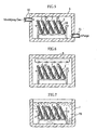
- the inner surface of the groove 20 may be brought into contact with water by immersing the substrates 2 in water 70 stored in a container 7, as shown in Fig. 7 .
- the secondary modifying step may be performed by replacing the mixed gas contained in the chamber 6 with air to bring moisture contained in the air into contact with the inner surface of the groove 20. In this case, use may be made of air which has been positively caused to contain moisture or indoor air.
- the bonding step is performed by interposing an adhesive sheet 4 between the substrate 2 and the cover 3, and then applying a pressing force to the adhesive sheet 4, as shown in Fig. 8 .
- the adhesive sheet 4 use may be made of one whose opposite surfaces are adherent and which is formed with openings 40 and 42 at locations corresponding to the sample introduction port 30, the reagent introduction port 31 and the air vent 32 of the substrate 2.
- the primary modifying step is performed by using a modifying gas (gas), whereas the secondary modifying step is performed by using gas or liquid such as water vapor or water. Since these substances do not have such linearity as that of ultraviolet rays, the substances such as a modifying gas and water vapor can be reliably brought into contact with the inner surface of the groove 20. Therefore, the entirety of the inner surface of the groove 20 can be hydrophilically treated reliably. Such an advantage can be obtained also in producing a microdevice 1 including a small flowpath (a groove 20 having a small sectional area). Moreover, since the apparatus for supplying amodifying gas, water or water vapor can have a simple structure and can be manufactured at a low cost, the method is advantageous also in terms of the manufacturing cost.
- a modifying gas gas
- the secondary modifying step is performed by using gas or liquid such as water vapor or water. Since these substances do not have such linearity as that of ultraviolet rays, the substances such as a modifying gas and water vapor can be reliably brought into contact with
- the present invention is not limited to the foregoing embodiments but may modified in various ways.
- the hydrophilization with respect to the substrate is performed before the cover is bonded to the substrate in the foregoing embodiments
- the hydrophilization may be performed after the cover is bonded to the substrate. In such a case, not only the inner surface of the groove but also the surface of the cover which faces the flow path can be hydrophilically treated.
- the method of the present invention is also applicable to such microdevices as one that mixes three or more liquids, one that is formed with a plurality of fluid paths for providing a plurality of reaction systems, and one which contains a reagent in the fluid path so that only a sample liquid is introduced to the fluid path.
- the method of the present invention is also applicable to microdevices for analyzing a sample by an electrochemical method as well as those for analyzing a sample by an optical method.
- the method of the present invention is also applicable to the case where a plurality of analytical tools are to be produced at the same time.
- a plate member including a plurality of portions which are later to become substrates may be formed by resin-molding, and then the plate member may be hydrophilically treated.
- another plate member including a plurality of portions which are to become covers is bonded to the plate member, and then the bonded product is cut, whereby a plurality of analytical tools are provided at the same time.
- an adhesive sheet and a cover in which through-holes are formed in advance are bonded to the substrate.
- through-holes may be formed in the adhesive sheet and the cover after the adhesive sheet and the cover are bonded to the substrate.
- the bonding of the cover to the substrate maynot necessarily be performed by using the adhesive sheet.
- the bonding may be performed by using an adhesive or by heat seal or ultrasonic fusing.
- hydrophilization can be properly performed not only with respect to a groove having a rectangular cross section but also to a groove having another cross sectional configuration such as a semi-circular cross section or a triangular cross section.
Abstract
Description
- The present invention relates to a method of producing an analytical tool which is used for analyzing a sample liquid and which is structured to move the sample liquid before the analysis.
- In one type of analytical tool, a sample liquid is caused to move by capillary action. Such an analytical tool includes a capillary for producing a capillary force. To properly exert the capillary force onto a sample liquid, the inner surface of the capillary is hydrophilically treated. For example, in the structure shown in
Fig. 9 , acapillary 93 is formed by covering agroove 91 formed in asubstrate 90 with acover 92. In this case, thebottom surface 91a of thegroove 91 and onesurface 92a of thecover 92 are hydrophilically treated. The hydrophilization treatment with respect to the inner surface of thecapillary 93 may be performed by ultraviolet irradiation, the application of a surface-active agent or plasma discharge such as glow discharge or corona discharge, for example. (SeeJP-A 2001-159618 JP-A 2002-168821 - Recently, there is a tendency to reduce the sectional area of the
capillary 93 to respond to the demand for the reduction of the amount of a sample liquid and the size reduction of an analytical tool. Particularly, in an analytical tool including a plurality of capillaries for analyzing a plurality of items, it is highly necessary to reduce the sectional area of each capillary. Since a typical analytical tool originally has a relatively small thickness, to effectively reduce the size of the analytical tool, the dimension of the tool as viewed in plan need be reduced. As shown inFig. 10 , to reduce the sectional area of each ofcapillaries 93 while reducing the size of the analytical tool as well, the width of eachcapillary 93 need be reduced. However, when the width of thecapillary 93 is reduced to reduce the sectional area, the proportion of the hydrophilically-treated surfaces decreases in the case where hydrophilization treatment is performed only with respect to thebottom surface 91a of eachgroove 91 and to onesurface 92a of thecover 92. Therefore, to properly move the sample liquid through the capillary 93, the hydrophilization treatment need be performed also with respect to theside surfaces 91b of thegroove 91. - However, it is difficult to hydrophilically treat the
side surfaces 91b of thegroove 91 by the application of a surface-active agent or ultraviolet irradiation. Specifically, since light such as ultraviolet rays has linearity, it is difficult to cause ultraviolet rays to impinge on theside surface 91b of such a small flow path (groove) 91 as shown inFig. 11A . - The hydrophilization treatment by the application of a surface-active agent is performed by supplying a liquid material containing a surface-active agent into the
groove 91 and then drying the liquid material. Therefore, to apply the surface-active agent to theside surfaces 91b of thegroove 91, it is necessary to completely fill thegroove 91 with the liquid material and then dry the liquid material, as shown inFig. 11B . In this way, since thegroove 91 is filled with the surface-active agent to apply the surface-active agent to the side surface of thegroove 91, the provision of a flow path having an intended sectional area is difficult. - Hydrophilization of microchannel structures in the surface of a planar substrate (polymethyl methacrylate) by oxygen plasma treatment or by an oxidation agent and subsequent coating with a hydrophylic non-ionic hydrophilic polymer is described in
WO01/47637 - The hydrophilization treatment by utilizing plasma discharge requires equipment for causing plasma discharge and hence requires high cost of equipment and manufacturing cost. Further, similarly to the hydrophilization treatment by ultraviolet irradiation, it is difficult to hydrophilically treat the
side surfaces 91b of thegroove 91 satisfactorily by plasma discharge. - An object of the present invention is to provide a method which is capable of properly performing hydrophilization even with respect to a small flow path without increasing the cost.
- According to the present invention, there is provided a method of producing an analytical tool which comprises a substrate made of a polymer material and formed with a groove for moving a sample liquid, and a cover bonded to the substrate to cover the groove. The method comprises hydrophilically treating an inner surface of the groove, characterized in that the substrate is made of polymethyl methacrylate. The hydrophilization treatment includes a primary modifying step for primarily modifying characteristics of the inner surface of the groove by bringing a modifying gas which contains fluorine gas and oxygen gas into contact with the inner surface of the groove to introduce a fluorine atom to a side chain or an end group as bonded to a ketone group in a polymer chain of said substrate, and a secondary modifying step for secondarily modifying the characteristics of the inner surface of the groove by replacing the fluorine atom previously introduced with a hydroxyl group such that a carboxyl group, which is a hydrophilic group, is introduced into a polymer chain existing at a surface of the substrate. Thus, the inner surface of the groove becomes hydrophilic. The degree of hydrophilization is such that the contact angle of pure water at the inner surface of the groove becomes 0-80 degrees, and preferably 0-60 degrees for example.
- The hydrophilization treatment may be performed before the cover is bonded to the substrate or after the cover is bonded to the substrate. In the latter case, when the cover is made of a polymer material, not only the inner surface of the groove but also the surface of the cover which faces the groove can be hydrophilically treated.
- The primary modifying step may be performed for 1-60 minutes under such conditions that the partial pressure of the modifying gas is maintained at 10-2000 hPa and temperature is maintained at 0-100°C, and preferably, the partial pressure of the modifying gas is maintained at 100-1100 hPa and temperature is maintained at 0-40 °C. Preferably, the mixing ratio of the fluorine gas and the oxygen gas is 1:1-1000 on a volume basis.
- For example, the secondary modifying step comprises bringing water or water vapor into contact with the inner surface of the groove. The bringing of water or water vapor into contact with the inner surface of the groove may comprise spraying water or water vapor to an inner surface of the substrate or immersing the substrate in a water bath. The substrate may be brought into contact with air for secondarily modifying the inner surface of the groove by the moisture contained in the air. In this case, use may be made of air which has been positively caused to contain moisture.
- The present invention is applicable to an analytical tool in which a sample liquid is caused to move by capillary action as a technique for making the inner surface of the fluid path hydrophilic. Particularly, the present invention is applicable to such an analytical tool as a microdevice which includes a small fluidpath. For example, the present invention is applicable to a microdevice which includes a fluid path having a principal cross section (corresponding to the principal cross section of the groove of the substrate) having a rectangular shape which has a width W of 10∼500 µm and a depth D of 5-500 µm and satisfies D/W≥0.5. The principal cross section" herein indicates a vertical section extending perpendicularly to the travel direction of the sample liquid, and indicates the vertical section of a portion which is mainly utilized for traveling the sample liquid when the sectional configuration is not uniform.
- In the present invention, the primary modifying step is performed by using modifying gas (fluorine gas and oxygen gas), whereas the secondary modifying step is performed by using gas or liquid such as water vapor or water, for example. Since these substances do not have such linearity as that of ultraviolet rays, the substances such as modifying gas and water vapor can be reliably brought into contact with the inner surface of the groove of the substrate. Therefore, the entirety of the inner surface of the groove can be hydrophilically treated reliably. Such an advantage can be obtained also in producing a microdevice including a small flow path (a groove having a small sectional area). Moreover, since the apparatus for supplying modifying gas, water or water vapor can have a simple structure and can be manufactured at a low cost, the method is advantageous in terms of the manufacturing cost.
-
-
Fig. 1 an entire perspective view showing an example of microdevice as an object to be produced by the method of the present invention. -
Fig. 2 is a sectional view taken along lines II-II inFig. 1 , part of which is shown as enlarged. -
Fig 3 is an entire perspective view showing the cover of the microdevice. -
Fig. 4 is an entire perspective view showing the substrate of the microdevice. -
Fig. 5 is a sectional view showing a primary modifying step of the hydrophilization step in the production method of the present invention. -
Fig. 6 is a sectional view showing a secondary modifying step of the hydrophilization step in the production method of the present invention. -
Fig. 7 is a sectional view showing another example of secondary modifying step of the hydrophilization step in the production method of the present invention. -
Fig. 8 is a sectional view showing a bonding step in the production method of the present invention. -
Fig. 9 is a sectional view of an analytical tool for describing a prior art method. -
Fig. 10 is a sectional view of an analytical tool for describing a prior art method. -
Figs. 11A and 11B are sectional views for describing prior art hydrophilization treatment. - The present invention relates to a method of producing an analytical tool which can be mounted, in use, to an analytical apparatus. In the analytical apparatus, a sample liquid supplied to the analytical tool can be analyzed by an optical method or an electrochemical method, for example.
-
Figs. 1-4 show an example of analytical tool which can be produced by a method according to the present invention. The describedanalytical tool 1 shown in the figures is a so-called microdevice and designed to perform analysis of a sample by an optical method. Themicrodevice 1, which serves to provide a reaction field, includes asubstrate 2 formed with agroove 20, and acover 3 bonded to thesubstrate 2 via an adhesive sheet 4 to cover thegroove 20. - As better shown in
Figs. 1 and4 , thegroove 20 includes asample introduction path 21, areagent introduction path 22 and areaction path 23. Thereaction path 23 has anend 23a connected to thesample introduction path 21 and thereagent introduction path 22. The entirety of thereaction path 23 has a serpentine shape to have a long length. Thereaction path 23 has anotherend 23b which provides a measurement portion to be irradiated with light from a measurement light source. - As shown in
Fig. 2 , thegroove 20 has a principal rectangular cross section which has a width W of 10-500 µm and a depth D of 5-500 µm and which satisfies D/W≥0.5. The inner surface of thegroove 20 is hydrophilically treated. The contact angle of pure water at the inner surface of thegroove 20 is 0-80 degrees, for example. - As shown in
Figs. 1 through 3 , thecover 3 includes asample introduction port 30, areagent introduction port 31 and anair vent 32. Thesample introduction port 30 is provided at a location corresponding to anend 21a of thesample introduction path 21, thereagent introduction port 31 provided at a location 8 corresponding to anend 22a of thereagent introduction path 22, and theair vent 32 provided at a location corresponding to theend 23b of thereaction path 23. - Also described is analyzing a sample wherein the sample and a reagent are introduced to the
microdevice 1 through thesample introduction port 30 and thereagent introduction port 31, respectively. The sample and the reagent move, by capillary action, through thesample introduction path 21 and thereagent introduction path 22, respectively, to merge at thereaction path 23. As a result, reaction between the sample and the reagent starts. The sample and the reagent, while undergoing the reaction, travel through thereaction path 23 toward theair vent 23 by capillary action and finally reach themeasurement portion 23b. At themeasurement portion 23b, the reaction product of the sample and the reagent is analyzed by the analytical apparatus, as noted above. - A method of producing the
microdevice 1 will be described below. Hereinafter, a method for producing a microdevice individually one by one will be exemplarily described. - The method of producing a
microdevice 1 includes a cover forming step, a substrate forming step, a hydrophilization step and a bonding step. - In the cover forming step, a transparent resin film, for example, is subjected to punching and then cut into an intended size (See
Fig. 3 ). By the punching, through-holes are formed, which are later to become thesample introduction port 30, thereagent introduction port 31 and theair vent 32. In the step for forming thecover 3, punching of the resin film may be performed after cutting of the resin film. One surface of thecover 3 may be hydrophilically treated by ultraviolet irradiation or the application of a surface-active agent. Examples of material of the resin film (material of the cover 3) include polymer materials such as polydimethylsiloxane (PDMS), polymethyl methacrylate (PMMA), polystyrene (PS), polycarbonate (PC) and polyethylene terephthalate (PET). The resin film (cover 3) may be made of a combination of at least two polymer materials. For example, the resin film (cover 3) may be made of a material provided by blending at least two of the polymer materials exemplified above. Alternatively, the resin film (cover 3) may be formed by bonding films or sheets which are made of different polymer materials together. - In the substrate forming step, a substrate is formed by injection molding using a thermoplastic resin, for example. In the injection molding, the
groove 20 can be formed in thesubstrate 2 by appropriately designing the configuration of the mold. Alternatively, thegroove 20 may be made by laser beam machining or etching, for example. Polylmer material of the substrate is polymethyl methacrylate (PMMA). - The hydrophilization step includes a primary modifying step for primarily modifying the characteristics of the inner surface of the
groove 20 by bringing a modifying gas into contact with the inner surface of thegroove 20, and a secondary modifying step for secondarily modifying the characteristics of the inner surface of thegroove 20. - As shown in
Fig. 5 , for example, the primary modifying step is performed with a plurality ofsubstrates 2 housed in achamber 5. To thechamber 5 are connected a modifyinggas supply pipe 50 for supplying the modifying gas to thechamber 5, and apurge pipe 51 for discharging gas from the chamber - As the modifying gas, use is made of gas containing fluorine gas and oxygen gas. The mixing ratio of fluorine gas and oxygen gas is 1:1-1000, and preferably, 1:10-20 on a volume basis. During the primary modifying step, the interior of the
chamber 5 is so maintained that the partial pressure of the modifying gas is 10-2000 hPa and the temperature is 0-100 °C, and preferably, the partial pressure of the modifying gas is 100-1100 hPa and the temperature is 0-40 °C. Under such conditions, thesubstrate 2 is kept in contact with the modifying gas for 1 to 60 minutes, for example. As a result, in a polymer chain forming thesubstrate 2, a fluorine atom is introduced to a side chain or an end group as bonded to a ketone group. - The secondary modifying step is performed by bringing water or water vapor into contact with the inner surface of the
groove 20. As a result, the fluorine atom previously introduced is replaced with a hydroxyl group, whereby a carboxyl group is introduced into the polymer chain. Thus, the inner surface of thegroove 20 becomes hydrophilic. - For example, the contact of the inner surface of the
groove 20 with water or water vapor may be performed by supplying water or water vapor to thechamber 6 accommodating thesubstrates 2, as shown inFig. 6 . Thesubstrates 2 may be brought into contact with water or water vapor in an open system. The inner surface of thegroove 20 may be brought into contact with water by immersing thesubstrates 2 inwater 70 stored in acontainer 7, as shown inFig. 7 . The secondary modifying step may be performed by replacing the mixed gas contained in thechamber 6 with air to bring moisture contained in the air into contact with the inner surface of thegroove 20. In this case, use may be made of air which has been positively caused to contain moisture or indoor air. - For example, the bonding step is performed by interposing an adhesive sheet 4 between the
substrate 2 and thecover 3, and then applying a pressing force to the adhesive sheet 4, as shown inFig. 8 . As the adhesive sheet 4, use may be made of one whose opposite surfaces are adherent and which is formed withopenings sample introduction port 30, thereagent introduction port 31 and theair vent 32 of thesubstrate 2. - In the hydrophilization step of this embodiment, the primary modifying step is performed by using a modifying gas (gas), whereas the secondary modifying step is performed by using gas or liquid such as water vapor or water. Since these substances do not have such linearity as that of ultraviolet rays, the substances such as a modifying gas and water vapor can be reliably brought into contact with the inner surface of the
groove 20. Therefore, the entirety of the inner surface of thegroove 20 can be hydrophilically treated reliably. Such an advantage can be obtained also in producing amicrodevice 1 including a small flowpath (agroove 20 having a small sectional area). Moreover, since the apparatus for supplying amodifying gas, water or water vapor can have a simple structure and can be manufactured at a low cost, the method is advantageous also in terms of the manufacturing cost. - The present invention is not limited to the foregoing embodiments but may modified in various ways. For example, although the hydrophilization with respect to the substrate is performed before the cover is bonded to the substrate in the foregoing embodiments, the hydrophilization may be performed after the cover is bonded to the substrate. In such a case, not only the inner surface of the groove but also the surface of the cover which faces the flow path can be hydrophilically treated.
- The method of the present invention is also applicable to such microdevices as one that mixes three or more liquids, one that is formed with a plurality of fluid paths for providing a plurality of reaction systems, and one which contains a reagent in the fluid path so that only a sample liquid is introduced to the fluid path. The method of the present invention is also applicable to microdevices for analyzing a sample by an electrochemical method as well as those for analyzing a sample by an optical method.
- The method of the present invention is also applicable to the case where a plurality of analytical tools are to be produced at the same time. For example, a plate member including a plurality of portions which are later to become substrates may be formed by resin-molding, and then the plate member may be hydrophilically treated. In this case, another plate member including a plurality of portions which are to become covers is bonded to the plate member, and then the bonded product is cut, whereby a plurality of analytical tools are provided at the same time.
- In the foregoing embodiments, an adhesive sheet and a cover in which through-holes are formed in advance are bonded to the substrate. However, through-holes may be formed in the adhesive sheet and the cover after the adhesive sheet and the cover are bonded to the substrate.
- The bonding of the cover to the substratemaynot necessarily be performed by using the adhesive sheet. For example, the bonding may be performed by using an adhesive or by heat seal or ultrasonic fusing.
- According to the present invention, hydrophilization can be properly performed not only with respect to a groove having a rectangular cross section but also to a groove having another cross sectional configuration such as a semi-circular cross section or a triangular cross section.
Claims (14)
- A method of producing an analytical tool comprising a substrate made of a polymer material and formed with a groove for moving a sample liquid, and a cover bonded to the substrate to cover the groove,
the method comprising hydrophilically treating an inner surface of the groove, characterised in that the substrate is made of polymethyl methacrylate, and the hydrophilization includes a primary modifying step for primarily modifying characteristics of the inner surface of the groove by bringing a modifying gas which contains fluorine gas and oxygen gas into contact with the inner surface of the groove to introduce a fluorine atom to a side chain or an end group as bonded to a ketone group in a polymer chain of said substrate, and a secondary modifying step for secondarily modifying the characteristics of the inner surface of the groove by replacing the fluorine atom previously introduced with a hydroxyl group such that a carboxyl group is introduced into the polymer chain. - The analytical tool producing method according to claim 1, wherein mixing ratio of the fluorine gas and the oxygen gas is 1:1-1000 on a volume basis.
- The analytical tool producing method according to claim 2, wherein mixing ratio of the fluorine gas and the oxygen gas is 1:10-20 on a volume basis.
- The analytical tool producing method according to claim 1, wherein the primary modifying step is performed for 1-60 minutes under conditions where partial pressure of the modifying gas is maintained at 10-2000 hPa and temperature is maintained at 0-100°C.
- The analytical tool producing method according to claim 4, wherein the partial pressure of the modifying gas is maintained at 100-1100 hPa and the temperature is maintained at 0-40°C.
- The analytical tool producing method according to claim 1, wherein the secondary modifying step comprises bringing water or water vapor into contact with the inner surface of the groove.
- The analytical tool producing method according to claim 6, wherein the bringing of water or water vapor into contact with the inner surface of the groove comprises spraying water or water vapor to an inner surface of the substrate.
- The analytical tool producing method according to claim 6, wherein the bringing of water or water vapor into contact with the inner surface of the groove comprises Immersing the substrate in a water bath.
- The analytical tool producing method according to claim 1, wherein the hydrophilization treatment is so performed that a contact angle of pure water at the inner surface of the groove becomes 0-80 degrees.
- The analytical tool producing method according to claim 9, wherein the contact angle is 0-60 degrees.
- The analytical tool producing method according to claim 1, wherein the analytical tool is designed to move the sample liquid by capillary action.
- The analytical tool producing method according to claim 11, wherein the groove has a principal, rectangular cross section which has a width W of 10-500 µm and a depth D of 5-500 µm and which satisfies D/W≥0.5.
- The analytical tool producing method according to claim 1, wherein the hydrophilization treatment is performed before the cover is bonded to the substrate.
- The analytical tool producing method according to claim 1, wherein the cover is made of a polymer material, and
wherein both of the inner surface of the groove and a surface of the cover which faces the groove are hydrophilically treated at the same time after the cover is bonded to the substrate.
Applications Claiming Priority (3)
| Application Number | Priority Date | Filing Date | Title |
|---|---|---|---|
| JP2002281102A JP4009683B2 (en) | 2002-09-26 | 2002-09-26 | Method for manufacturing analytical tool |
| JP2002281102 | 2002-09-26 | ||
| PCT/JP2003/012296 WO2004029632A1 (en) | 2002-09-26 | 2003-09-25 | Method of producing analytical tool |
Publications (3)
| Publication Number | Publication Date |
|---|---|
| EP1548447A1 EP1548447A1 (en) | 2005-06-29 |
| EP1548447A4 EP1548447A4 (en) | 2010-11-03 |
| EP1548447B1 true EP1548447B1 (en) | 2012-01-11 |
Family
ID=32040501
Family Applications (1)
| Application Number | Title | Priority Date | Filing Date |
|---|---|---|---|
| EP03798514A Expired - Lifetime EP1548447B1 (en) | 2002-09-26 | 2003-09-25 | Method of producing analytical tool |
Country Status (7)
| Country | Link |
|---|---|
| US (1) | US7842343B2 (en) |
| EP (1) | EP1548447B1 (en) |
| JP (1) | JP4009683B2 (en) |
| CN (1) | CN1685237B (en) |
| AT (1) | ATE541217T1 (en) |
| AU (1) | AU2003266638A1 (en) |
| WO (1) | WO2004029632A1 (en) |
Families Citing this family (4)
| Publication number | Priority date | Publication date | Assignee | Title |
|---|---|---|---|---|
| WO2006095615A1 (en) * | 2005-03-07 | 2006-09-14 | Kuraray Co., Ltd. | Microchannel array and method for producing the same, and blood measuring method employing it |
| JP4766516B2 (en) * | 2006-03-17 | 2011-09-07 | 岡山県 | Method for hydrophilizing microchannels |
| KR101436387B1 (en) * | 2007-10-05 | 2014-09-02 | 삼성전자주식회사 | Image Drum and Method For Manufacturing Thereof |
| JP6312440B2 (en) * | 2013-04-03 | 2018-04-18 | 日精株式会社 | Capillary blood collection tool |
Citations (3)
| Publication number | Priority date | Publication date | Assignee | Title |
|---|---|---|---|---|
| JPS6088044A (en) * | 1983-10-21 | 1985-05-17 | Mitsubishi Rayon Co Ltd | Treatment to make plastic capillary tube hydrophilic |
| US6419995B1 (en) * | 2000-03-08 | 2002-07-16 | Wolff Walsrode Ag | Process for the surface activation of materials |
| US20020092767A1 (en) * | 1997-09-19 | 2002-07-18 | Aclara Biosciences, Inc. | Multiple array microfluidic device units |
Family Cites Families (15)
| Publication number | Priority date | Publication date | Assignee | Title |
|---|---|---|---|---|
| US5151183A (en) * | 1989-05-18 | 1992-09-29 | Allied-Signal Inc. | Reduction of membrane fouling by surface fluorination |
| US5798261A (en) * | 1989-10-31 | 1998-08-25 | The United States Of America As Represented By The Administrator Of The National Aeronautics And Space Administration | Distributed pore chemistry in porous organic polymers |
| NL9100815A (en) * | 1991-05-10 | 1992-12-01 | Kema Nv | METHOD FOR MANUFACTURING AN IONOMER |
| US5478751A (en) * | 1993-12-29 | 1995-12-26 | Abbott Laboratories | Self-venting immunodiagnositic devices and methods of performing assays |
| JP3569715B2 (en) * | 1996-07-29 | 2004-09-29 | アークレイ株式会社 | Tool for analyzing liquid sample and method for producing the same |
| DE69933376T2 (en) | 1998-06-05 | 2007-08-02 | Arkray, Inc. | DEVICE FOR MEASURING ION ACTIVITY |
| SE9901100D0 (en) * | 1999-03-24 | 1999-03-24 | Amersham Pharm Biotech Ab | Surface and tis manufacture and uses |
| EP1235068B1 (en) | 1999-11-15 | 2006-01-25 | ARKRAY, Inc. | Biosensor |
| JP2001159618A (en) | 1999-12-03 | 2001-06-12 | Matsushita Electric Ind Co Ltd | Biosensor |
| SE9904802D0 (en) * | 1999-12-23 | 1999-12-23 | Amersham Pharm Biotech Ab | Microfluidic surfaces |
| JP2001294692A (en) | 2000-04-13 | 2001-10-23 | Mitsubishi Chemicals Corp | Article having hydrophilic surface |
| EP2096437B1 (en) * | 2000-11-30 | 2014-11-19 | Panasonic Healthcare Co., Ltd. | Biosensor for quantifying substrate |
| JP4639465B2 (en) | 2000-11-30 | 2011-02-23 | パナソニック株式会社 | Biosensor |
| AU2904602A (en) * | 2000-12-11 | 2002-06-24 | Harvard College | Nanosensors |
| JP4860828B2 (en) | 2001-02-01 | 2012-01-25 | ダイワボウホールディングス株式会社 | Polyolefin fiber for cement reinforcement and method for producing the same |
-
2002
- 2002-09-26 JP JP2002281102A patent/JP4009683B2/en not_active Expired - Fee Related
-
2003
- 2003-09-25 AT AT03798514T patent/ATE541217T1/en active
- 2003-09-25 EP EP03798514A patent/EP1548447B1/en not_active Expired - Lifetime
- 2003-09-25 WO PCT/JP2003/012296 patent/WO2004029632A1/en active Application Filing
- 2003-09-25 US US10/529,321 patent/US7842343B2/en not_active Expired - Fee Related
- 2003-09-25 AU AU2003266638A patent/AU2003266638A1/en not_active Abandoned
- 2003-09-25 CN CN03822687.1A patent/CN1685237B/en not_active Expired - Fee Related
Patent Citations (3)
| Publication number | Priority date | Publication date | Assignee | Title |
|---|---|---|---|---|
| JPS6088044A (en) * | 1983-10-21 | 1985-05-17 | Mitsubishi Rayon Co Ltd | Treatment to make plastic capillary tube hydrophilic |
| US20020092767A1 (en) * | 1997-09-19 | 2002-07-18 | Aclara Biosciences, Inc. | Multiple array microfluidic device units |
| US6419995B1 (en) * | 2000-03-08 | 2002-07-16 | Wolff Walsrode Ag | Process for the surface activation of materials |
Also Published As
| Publication number | Publication date |
|---|---|
| JP4009683B2 (en) | 2007-11-21 |
| JP2004117179A (en) | 2004-04-15 |
| US20060118403A1 (en) | 2006-06-08 |
| EP1548447A1 (en) | 2005-06-29 |
| ATE541217T1 (en) | 2012-01-15 |
| WO2004029632A1 (en) | 2004-04-08 |
| EP1548447A4 (en) | 2010-11-03 |
| CN1685237A (en) | 2005-10-19 |
| US7842343B2 (en) | 2010-11-30 |
| CN1685237B (en) | 2011-03-23 |
| AU2003266638A1 (en) | 2004-04-19 |
Similar Documents
| Publication | Publication Date | Title |
|---|---|---|
| US8377393B2 (en) | Microchip | |
| EP1735097B1 (en) | Nanoliter array loading | |
| US9644794B2 (en) | Flow cell with cavity and diaphragm | |
| US7740472B2 (en) | Method and device for flowing a liquid on a surface | |
| US7204139B2 (en) | Analytical chip, analytical-chip unit, and analysis apparatus | |
| JP4142280B2 (en) | Apparatus for fluid analysis and controlled transport of fluids | |
| CA2690165C (en) | Method for the production of a microfluidic system on a polymer surface | |
| US20060002825A1 (en) | Microfludic devices with new inner surfaces | |
| US20040112518A1 (en) | Polymer bonding by means of plasma activation | |
| EP1977829A1 (en) | Device for performing multiple analyses in parallel | |
| US20090060787A1 (en) | Method for uniform analyte fluid delivery to microarrays | |
| US20090060786A1 (en) | Microfluidic apparatus for wide area microarrays | |
| EP1548447B1 (en) | Method of producing analytical tool | |
| JP2003043052A (en) | Microchannel chip, microchannel system and circulation control method in microchannel chip | |
| CN114390948A (en) | Micro-fluidic chip, production method and application | |
| KR102350365B1 (en) | Anti-bubble formation microfluidic chip and preparation method thereof | |
| EP1492724A1 (en) | Microfluidic devices with new inner surfaces | |
| EP2240600B1 (en) | Microfluidic apparatus for wide area microarrays | |
| EP1261426B1 (en) | Test sample card and method of its use | |
| JP4072175B2 (en) | Substrate bonding method, chip forming method, and chip | |
| JP6049446B2 (en) | Microchip | |
| CN112955537A (en) | Cell culture substrate and method for producing same | |
| Zimmer et al. | Shrinking the apparatus size for DNA analysis | |
| CN220590057U (en) | Mixed micro-fluid platform based on filter paper | |
| US20240084368A1 (en) | Microfluidic system consisting of a folded foil, and production method |
Legal Events
| Date | Code | Title | Description |
|---|---|---|---|
| PUAI | Public reference made under article 153(3) epc to a published international application that has entered the european phase |
Free format text: ORIGINAL CODE: 0009012 |
|
| 17P | Request for examination filed |
Effective date: 20050407 |
|
| AK | Designated contracting states |
Kind code of ref document: A1 Designated state(s): AT BE BG CH CY CZ DE DK EE ES FI FR GB GR HU IE IT LI LU MC NL PT RO SE SI SK TR |
|
| AX | Request for extension of the european patent |
Extension state: AL LT LV MK |
|
| DAX | Request for extension of the european patent (deleted) | ||
| A4 | Supplementary search report drawn up and despatched |
Effective date: 20101001 |
|
| RIC1 | Information provided on ipc code assigned before grant |
Ipc: G01N 1/00 20060101ALI20100927BHEP Ipc: G01N 1/10 20060101ALI20100927BHEP Ipc: C08J 7/00 20060101ALI20100927BHEP Ipc: G01N 37/00 20060101ALI20100927BHEP Ipc: G01N 31/20 20060101ALI20100927BHEP Ipc: G01N 27/28 20060101ALI20100927BHEP Ipc: G01N 33/52 20060101ALI20100927BHEP Ipc: G01N 35/08 20060101AFI20040414BHEP Ipc: G01N 33/543 20060101ALI20100927BHEP |
|
| 17Q | First examination report despatched |
Effective date: 20101213 |
|
| GRAP | Despatch of communication of intention to grant a patent |
Free format text: ORIGINAL CODE: EPIDOSNIGR1 |
|
| RIC1 | Information provided on ipc code assigned before grant |
Ipc: G01N 35/08 20060101AFI20110706BHEP Ipc: G01N 27/28 20060101ALI20110706BHEP Ipc: G01N 33/543 20060101ALI20110706BHEP Ipc: C08J 7/00 20060101ALI20110706BHEP Ipc: G01N 37/00 20060101ALI20110706BHEP Ipc: G01N 31/20 20060101ALI20110706BHEP Ipc: G01N 1/10 20060101ALI20110706BHEP Ipc: G01N 1/00 20060101ALI20110706BHEP Ipc: G01N 33/52 20060101ALI20110706BHEP |
|
| GRAS | Grant fee paid |
Free format text: ORIGINAL CODE: EPIDOSNIGR3 |
|
| GRAA | (expected) grant |
Free format text: ORIGINAL CODE: 0009210 |
|
| RIN1 | Information on inventor provided before grant (corrected) |
Inventor name: KITAMURA, SHIGERU, Inventor name: NODA, YUICHIRO, Inventor name: TAKAMA, TOSHIO, Inventor name: TAGUCHI, TAKAYUKI, |
|
| AK | Designated contracting states |
Kind code of ref document: B1 Designated state(s): AT BE BG CH CY CZ DE DK EE ES FI FR GB GR HU IE IT LI LU MC NL PT RO SE SI SK TR |
|
| REG | Reference to a national code |
Ref country code: GB Ref legal event code: FG4D |
|
| REG | Reference to a national code |
Ref country code: CH Ref legal event code: EP |
|
| REG | Reference to a national code |
Ref country code: AT Ref legal event code: REF Ref document number: 541217 Country of ref document: AT Kind code of ref document: T Effective date: 20120115 |
|
| REG | Reference to a national code |
Ref country code: IE Ref legal event code: FG4D |
|
| REG | Reference to a national code |
Ref country code: DE Ref legal event code: R096 Ref document number: 60339716 Country of ref document: DE Effective date: 20120308 |
|
| REG | Reference to a national code |
Ref country code: NL Ref legal event code: VDEP Effective date: 20120111 |
|
| PG25 | Lapsed in a contracting state [announced via postgrant information from national office to epo] |
Ref country code: SI Free format text: LAPSE BECAUSE OF FAILURE TO SUBMIT A TRANSLATION OF THE DESCRIPTION OR TO PAY THE FEE WITHIN THE PRESCRIBED TIME-LIMIT Effective date: 20120111 |
|
| PG25 | Lapsed in a contracting state [announced via postgrant information from national office to epo] |
Ref country code: NL Free format text: LAPSE BECAUSE OF FAILURE TO SUBMIT A TRANSLATION OF THE DESCRIPTION OR TO PAY THE FEE WITHIN THE PRESCRIBED TIME-LIMIT Effective date: 20120111 Ref country code: BG Free format text: LAPSE BECAUSE OF FAILURE TO SUBMIT A TRANSLATION OF THE DESCRIPTION OR TO PAY THE FEE WITHIN THE PRESCRIBED TIME-LIMIT Effective date: 20120411 Ref country code: BE Free format text: LAPSE BECAUSE OF FAILURE TO SUBMIT A TRANSLATION OF THE DESCRIPTION OR TO PAY THE FEE WITHIN THE PRESCRIBED TIME-LIMIT Effective date: 20120111 |
|
| PG25 | Lapsed in a contracting state [announced via postgrant information from national office to epo] |
Ref country code: GR Free format text: LAPSE BECAUSE OF FAILURE TO SUBMIT A TRANSLATION OF THE DESCRIPTION OR TO PAY THE FEE WITHIN THE PRESCRIBED TIME-LIMIT Effective date: 20120412 Ref country code: PT Free format text: LAPSE BECAUSE OF FAILURE TO SUBMIT A TRANSLATION OF THE DESCRIPTION OR TO PAY THE FEE WITHIN THE PRESCRIBED TIME-LIMIT Effective date: 20120511 Ref country code: FI Free format text: LAPSE BECAUSE OF FAILURE TO SUBMIT A TRANSLATION OF THE DESCRIPTION OR TO PAY THE FEE WITHIN THE PRESCRIBED TIME-LIMIT Effective date: 20120111 |
|
| REG | Reference to a national code |
Ref country code: AT Ref legal event code: MK05 Ref document number: 541217 Country of ref document: AT Kind code of ref document: T Effective date: 20120111 |
|
| PG25 | Lapsed in a contracting state [announced via postgrant information from national office to epo] |
Ref country code: CY Free format text: LAPSE BECAUSE OF FAILURE TO SUBMIT A TRANSLATION OF THE DESCRIPTION OR TO PAY THE FEE WITHIN THE PRESCRIBED TIME-LIMIT Effective date: 20120111 |
|
| PG25 | Lapsed in a contracting state [announced via postgrant information from national office to epo] |
Ref country code: DK Free format text: LAPSE BECAUSE OF FAILURE TO SUBMIT A TRANSLATION OF THE DESCRIPTION OR TO PAY THE FEE WITHIN THE PRESCRIBED TIME-LIMIT Effective date: 20120111 Ref country code: EE Free format text: LAPSE BECAUSE OF FAILURE TO SUBMIT A TRANSLATION OF THE DESCRIPTION OR TO PAY THE FEE WITHIN THE PRESCRIBED TIME-LIMIT Effective date: 20120111 Ref country code: CZ Free format text: LAPSE BECAUSE OF FAILURE TO SUBMIT A TRANSLATION OF THE DESCRIPTION OR TO PAY THE FEE WITHIN THE PRESCRIBED TIME-LIMIT Effective date: 20120111 Ref country code: SE Free format text: LAPSE BECAUSE OF FAILURE TO SUBMIT A TRANSLATION OF THE DESCRIPTION OR TO PAY THE FEE WITHIN THE PRESCRIBED TIME-LIMIT Effective date: 20120111 Ref country code: RO Free format text: LAPSE BECAUSE OF FAILURE TO SUBMIT A TRANSLATION OF THE DESCRIPTION OR TO PAY THE FEE WITHIN THE PRESCRIBED TIME-LIMIT Effective date: 20120111 |
|
| PLBE | No opposition filed within time limit |
Free format text: ORIGINAL CODE: 0009261 |
|
| STAA | Information on the status of an ep patent application or granted ep patent |
Free format text: STATUS: NO OPPOSITION FILED WITHIN TIME LIMIT |
|
| PG25 | Lapsed in a contracting state [announced via postgrant information from national office to epo] |
Ref country code: SK Free format text: LAPSE BECAUSE OF FAILURE TO SUBMIT A TRANSLATION OF THE DESCRIPTION OR TO PAY THE FEE WITHIN THE PRESCRIBED TIME-LIMIT Effective date: 20120111 |
|
| 26N | No opposition filed |
Effective date: 20121012 |
|
| PG25 | Lapsed in a contracting state [announced via postgrant information from national office to epo] |
Ref country code: AT Free format text: LAPSE BECAUSE OF FAILURE TO SUBMIT A TRANSLATION OF THE DESCRIPTION OR TO PAY THE FEE WITHIN THE PRESCRIBED TIME-LIMIT Effective date: 20120111 |
|
| REG | Reference to a national code |
Ref country code: DE Ref legal event code: R097 Ref document number: 60339716 Country of ref document: DE Effective date: 20121012 |
|
| PG25 | Lapsed in a contracting state [announced via postgrant information from national office to epo] |
Ref country code: ES Free format text: LAPSE BECAUSE OF FAILURE TO SUBMIT A TRANSLATION OF THE DESCRIPTION OR TO PAY THE FEE WITHIN THE PRESCRIBED TIME-LIMIT Effective date: 20120422 Ref country code: MC Free format text: LAPSE BECAUSE OF NON-PAYMENT OF DUE FEES Effective date: 20120930 |
|
| REG | Reference to a national code |
Ref country code: CH Ref legal event code: PL |
|
| REG | Reference to a national code |
Ref country code: IE Ref legal event code: MM4A |
|
| PG25 | Lapsed in a contracting state [announced via postgrant information from national office to epo] |
Ref country code: LI Free format text: LAPSE BECAUSE OF NON-PAYMENT OF DUE FEES Effective date: 20120930 Ref country code: IE Free format text: LAPSE BECAUSE OF NON-PAYMENT OF DUE FEES Effective date: 20120925 Ref country code: CH Free format text: LAPSE BECAUSE OF NON-PAYMENT OF DUE FEES Effective date: 20120930 |
|
| PG25 | Lapsed in a contracting state [announced via postgrant information from national office to epo] |
Ref country code: TR Free format text: LAPSE BECAUSE OF FAILURE TO SUBMIT A TRANSLATION OF THE DESCRIPTION OR TO PAY THE FEE WITHIN THE PRESCRIBED TIME-LIMIT Effective date: 20120111 |
|
| PG25 | Lapsed in a contracting state [announced via postgrant information from national office to epo] |
Ref country code: LU Free format text: LAPSE BECAUSE OF NON-PAYMENT OF DUE FEES Effective date: 20120925 |
|
| PG25 | Lapsed in a contracting state [announced via postgrant information from national office to epo] |
Ref country code: HU Free format text: LAPSE BECAUSE OF FAILURE TO SUBMIT A TRANSLATION OF THE DESCRIPTION OR TO PAY THE FEE WITHIN THE PRESCRIBED TIME-LIMIT Effective date: 20030925 |
|
| REG | Reference to a national code |
Ref country code: FR Ref legal event code: PLFP Year of fee payment: 14 |
|
| PGFP | Annual fee paid to national office [announced via postgrant information from national office to epo] |
Ref country code: GB Payment date: 20160920 Year of fee payment: 14 Ref country code: DE Payment date: 20160921 Year of fee payment: 14 |
|
| PGFP | Annual fee paid to national office [announced via postgrant information from national office to epo] |
Ref country code: FR Payment date: 20160921 Year of fee payment: 14 |
|
| PGFP | Annual fee paid to national office [announced via postgrant information from national office to epo] |
Ref country code: IT Payment date: 20160922 Year of fee payment: 14 |
|
| REG | Reference to a national code |
Ref country code: DE Ref legal event code: R119 Ref document number: 60339716 Country of ref document: DE |
|
| GBPC | Gb: european patent ceased through non-payment of renewal fee |
Effective date: 20170925 |
|
| REG | Reference to a national code |
Ref country code: FR Ref legal event code: ST Effective date: 20180531 |
|
| PG25 | Lapsed in a contracting state [announced via postgrant information from national office to epo] |
Ref country code: DE Free format text: LAPSE BECAUSE OF NON-PAYMENT OF DUE FEES Effective date: 20180404 Ref country code: GB Free format text: LAPSE BECAUSE OF NON-PAYMENT OF DUE FEES Effective date: 20170925 |
|
| PG25 | Lapsed in a contracting state [announced via postgrant information from national office to epo] |
Ref country code: FR Free format text: LAPSE BECAUSE OF NON-PAYMENT OF DUE FEES Effective date: 20171002 Ref country code: IT Free format text: LAPSE BECAUSE OF NON-PAYMENT OF DUE FEES Effective date: 20170925 |