EP1548393A1 - Dispositif de déconfinement d'une enveloppe de munition - Google Patents
Dispositif de déconfinement d'une enveloppe de munition Download PDFInfo
- Publication number
- EP1548393A1 EP1548393A1 EP04292927A EP04292927A EP1548393A1 EP 1548393 A1 EP1548393 A1 EP 1548393A1 EP 04292927 A EP04292927 A EP 04292927A EP 04292927 A EP04292927 A EP 04292927A EP 1548393 A1 EP1548393 A1 EP 1548393A1
- Authority
- EP
- European Patent Office
- Prior art keywords
- rocket
- explosive charge
- vent
- deconfining
- ammunition
- Prior art date
- Legal status (The legal status is an assumption and is not a legal conclusion. Google has not performed a legal analysis and makes no representation as to the accuracy of the status listed.)
- Granted
Links
- 239000002360 explosive Substances 0.000 claims abstract description 25
- 238000010304 firing Methods 0.000 claims abstract description 5
- 230000000977 initiatory effect Effects 0.000 claims description 9
- 229920001296 polysiloxane Polymers 0.000 claims description 6
- 230000037452 priming Effects 0.000 claims description 4
- 238000010079 rubber tapping Methods 0.000 claims description 4
- 238000005474 detonation Methods 0.000 description 8
- 239000007789 gas Substances 0.000 description 6
- 239000000463 material Substances 0.000 description 4
- 238000000354 decomposition reaction Methods 0.000 description 3
- 229910000831 Steel Inorganic materials 0.000 description 1
- 230000015556 catabolic process Effects 0.000 description 1
- 238000006731 degradation reaction Methods 0.000 description 1
- 230000006866 deterioration Effects 0.000 description 1
- 230000005489 elastic deformation Effects 0.000 description 1
- 239000006023 eutectic alloy Substances 0.000 description 1
- 238000010438 heat treatment Methods 0.000 description 1
- 238000003754 machining Methods 0.000 description 1
- 239000010959 steel Substances 0.000 description 1
- 238000005979 thermal decomposition reaction Methods 0.000 description 1
Images
Classifications
-
- F—MECHANICAL ENGINEERING; LIGHTING; HEATING; WEAPONS; BLASTING
- F42—AMMUNITION; BLASTING
- F42C—AMMUNITION FUZES; ARMING OR SAFETY MEANS THEREFOR
- F42C19/00—Details of fuzes
- F42C19/02—Fuze bodies; Fuze housings
-
- F—MECHANICAL ENGINEERING; LIGHTING; HEATING; WEAPONS; BLASTING
- F42—AMMUNITION; BLASTING
- F42B—EXPLOSIVE CHARGES, e.g. FOR BLASTING, FIREWORKS, AMMUNITION
- F42B39/00—Packaging or storage of ammunition or explosive charges; Safety features thereof; Cartridge belts or bags
- F42B39/20—Packages or ammunition having valves for pressure-equalising; Packages or ammunition having plugs for pressure release, e.g. meltable ; Blow-out panels; Venting arrangements
Definitions
- the technical field of the invention is that of devices ensuring the deconfinement of an envelope of ammunition containing an explosive charge.
- Deconfining devices make it possible to avoid detonation of a shell as a result of a warm-up example during a fire.
- Patent DE2131748 thus describes a closure cap of a shell body that is put in place when the shell is stored.
- This cap has a closure plate which is connected by a fusible material. The temperature rise releases the plate which allows the evacuation of gases.
- the warm-up can lead to initiation of the loading itself as a result of the increase of pressure, only at the initiation of the rocket which also causes the detonation of the load explosive.
- the object of the invention is to propose a device for deconfinement allowing for a simple way of ensuring a protection against accidental initiations as well due to the heating of the rocket rather than the loading explosive itself.
- the deconfining device according to the invention allows also to provide protection when the rocket is not mounted on the ammunition.
- the subject of the invention is a device for deconfinement of an envelope of a munition containing a explosive charge that may be initiated by a rocket priming device comprising at least one vent unstoppable to connect the explosive charge to the open air, device which is characterized in that the vent leads into a chamber located between the rocket and the explosive charge.
- the vent is carried by a connecting ring ensuring the connection of the casing and the priming rocket, ring delimiting the internal chamber inside which opens the vent, the chamber being closed on the side of the explosive charge by a bottom forming a projectable plate on the explosive charge during the initiation of the rocket.
- the bottom may include at least one circular groove ensuring a decrease in its thickness, and in a way preferred, at least two concentric circular grooves.
- the connecting ring can carry a thread allowing its connection to the casing and a tapping authorizing the fixation of the rocket.
- the vent may be closed with a silicone stopper.
- a munition 1 comprises an envelope 2 enclosing an explosive charge 3 which is bootable through a hole 2a of the envelope.
- the explosive charge 3 can be initiated by a rocket 4 which is secured to the envelope 2 of the munition by a connecting ring 5.
- the means of solidarization may for example include a tapping internal ring 5 cooperating with threads of the envelope 2 and the rocket.
- the firing rocket 4 is not shown in detail. Such components are conventional and well known to humans of career.
- the deconfining device comprises at least one vent 6 solidarityobturable (here four vents regularly distributed angularly).
- the vents are arranged through the ring 5 and thus communicate with the outside an inner chamber 7 delimited by the ring 5.
- Each vent 6 is closed by a plug 8 of a material which makes it possible to seal (for example silicone).
- This cap is made with a slightly conical shape and it is placed in the vent by elastic deformation.
- vents 6 open to the interior of the ammunition 1 in room 7 between the rocket 4 and the explosive charge 3.
- This tensionobturation intervenes indifferently if the increase in pressure results from a deterioration of the rocket 4 or if it is caused by the degradation of the explosive charge 3 itself.
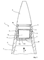
- FIG. 2 shows another embodiment of the invention
- the ammunition 1 is an artillery shell.
- the rocket 4 is screwed onto a connecting ring 5 which has an external thread 5a allowing its fixing by screwing on the envelope 2 of the shell.
- Ring 5 has also a tapping 5b for receiving the rocket 4.
- the ring 5 delimits an internal chamber 7 which is partly occupied by a detonation relay 9 integral with the rocket 4.
- This chamber 7 is closed on the explosive loading side 3 by a bottom 10 forming a projectable plate on the load explosive during the initiation of the rocket 4.
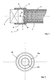
- the bottom 10 has two concentric circular grooves 11a and 11b which are more particularly visible on the figure 3.
- the ring 5 is made of steel.
- the thickness of the ring at the bottom 10 is about 1 mm.
- the initiation of the rocket 4 causes a cut of the bottom 10 at the level of the gorge 11a whose diameter is close to that of relay 9.
- Such a closed connection ring constitutes the object EP977005.
- the two grooves 11a and 11b allow the device to work perfectly even with variations in the radial and longitudinal positions of firing the rocket.
- the ring 5 also carries vents 6 closed by silicone plugs 8. These vents allow to connect the room 7 outside the ammunition.
- vents 6 do not disturb the normal operation of the ammunition. Indeed the kinetics of the detonation of rocket 4 and its relay is much more faster than that of the decomposition of the relay that would be due at a temperature rise.
- the thermal decomposition of relay 4 simply causes the ejection of the plugs 8, the deconfinement of the chamber 7 thus preventing the subsequent detonation of the relay as a result of an elevation pressure in the room.
- the deconfining device allows to ensure in a simple and reliable way the protection ammunition with a firing rocket.
- vents another material than a silicone plug, by example a fusible material with a given elevation of the temperature (such as a eutectic alloy).
Landscapes
- Engineering & Computer Science (AREA)
- General Engineering & Computer Science (AREA)
- Portable Nailing Machines And Staplers (AREA)
- Pressure Vessels And Lids Thereof (AREA)
- Fuses (AREA)
- Viewfinders (AREA)
- Filling Or Discharging Of Gas Storage Vessels (AREA)
- Toys (AREA)
- Manipulator (AREA)
Abstract
Description
- La figure 1 est une coupe schématique partielle d'une munition équipée d'un dispositif selon un mode de réalisation de l'invention,
- la figure 2 est une coupe longitudinale partielle d'une munition équipée d'un dispositif selon un autre mode de réalisation de l'invention,
- la figure 3 est une vue de la bague de liaison seule suivant la direction repérée F à la figure 2.
Claims (6)
- Dispositif de déconfinement d'une enveloppe (2) d'une munition (1) renfermant un chargement explosif (3) pouvant être initié par une fusée d'amorçage (4), dispositif comprenant au moins un évent (6) désobturable permettant de relier le chargement explosif (3) à l'air libre, dispositif caractérisé en ce que l'évent (6) débouche dans une chambre (7) située entre la fusée (4) et le chargement explosif (3).
- Dispositif de déconfinement selon la revendication 1, caractérisé en ce que l'évent (6) est porté par une bague de raccordement (5) assurant la liaison de l'enveloppe (2) et de la fusée d'amorçage (4), bague délimitant la chambre interne (7) à l'intérieur de laquelle débouche l'évent (6), la chambre (7) étant fermée du côté du chargement explosif (3) par un fond (10) formant une plaque projetable sur le chargement explosif lors de l'initiation de la fusée.
- Dispositif de déconfinement selon la revendication 2, caractérisé en ce que le fond (10) comporte au moins une gorge circulaire (11a,11b) assurant une diminution de son épaisseur.
- Dispositif de déconfinement selon la revendication 3, caractérisé en ce que le fond (10) comporte au moins deux gorges circulaires concentriques (11a,11b) .
- Dispositif de déconfinement selon une des revendications 2 à 4, caractérisé en ce que la bague de raccordement (5) porte un filetage (5a) permettant sa liaison à l'enveloppe (2) et un taraudage (5b) autorisant la fixation de la fusée (4).
- Dispositif de déconfinement selon une des revendications 1 à 5, caractérisé en ce que l'évent (6) est obturé par un bouchon en silicone (8).
Applications Claiming Priority (2)
| Application Number | Priority Date | Filing Date | Title |
|---|---|---|---|
| FR0315338A FR2864219B1 (fr) | 2003-12-22 | 2003-12-22 | Dispositif de deconfinement d'une enveloppe de munition |
| FR0315338 | 2003-12-22 |
Publications (2)
| Publication Number | Publication Date |
|---|---|
| EP1548393A1 true EP1548393A1 (fr) | 2005-06-29 |
| EP1548393B1 EP1548393B1 (fr) | 2016-03-09 |
Family
ID=34531350
Family Applications (1)
| Application Number | Title | Priority Date | Filing Date |
|---|---|---|---|
| EP04292927.3A Expired - Lifetime EP1548393B1 (fr) | 2003-12-22 | 2004-12-09 | Dispositif de déconfinement d'une enveloppe de munition |
Country Status (8)
| Country | Link |
|---|---|
| US (1) | US7353755B2 (fr) |
| EP (1) | EP1548393B1 (fr) |
| AU (1) | AU2004240225B2 (fr) |
| CA (1) | CA2490730C (fr) |
| ES (1) | ES2569520T3 (fr) |
| FR (1) | FR2864219B1 (fr) |
| PL (1) | PL1548393T3 (fr) |
| ZA (1) | ZA200410233B (fr) |
Cited By (1)
| Publication number | Priority date | Publication date | Assignee | Title |
|---|---|---|---|---|
| EP1978327A3 (fr) * | 2007-04-05 | 2010-06-23 | JUNGHANS Microtec GmbH | Projectile pénétrant |
Families Citing this family (15)
| Publication number | Priority date | Publication date | Assignee | Title |
|---|---|---|---|---|
| FR2906606B1 (fr) | 2006-09-29 | 2010-12-31 | Giat Ind Sa | Dispositif de deconfinement d'une enveloppe d'une munition. |
| FR2948186B1 (fr) * | 2009-07-17 | 2015-02-20 | Tda Armements Sas | Munition comprenant des moyens pour neutraliser son chargement explosif |
| US9964387B2 (en) * | 2009-08-19 | 2018-05-08 | Orbital Atk, Inc. | Insensitive munitions swaged vent plug |
| EP2473816B1 (fr) * | 2009-09-03 | 2015-03-04 | KMS Consulting LLC | Système de limitation de pression pour munition à douille |
| DE102013014811B4 (de) | 2013-09-05 | 2015-04-09 | Diehl Bgt Defence Gmbh & Co. Kg | Geschoss |
| FR3039267B1 (fr) * | 2015-07-24 | 2017-07-14 | Nexter Munitions | Dispositif de securite et d'armement pour une fusee d'ogive et fusee comportant un tel dispositif |
| US10088285B1 (en) * | 2016-12-15 | 2018-10-02 | The United States Of America As Represented By The Secretary Of The Navy | Cook-off mitigation systems using an uncanistered outgassing pad |
| US10724836B1 (en) * | 2016-12-15 | 2020-07-28 | The United States Of America, As Represented By The Secretary Of The Navy | Cook-off mitigation systems |
| US10101139B1 (en) * | 2016-12-15 | 2018-10-16 | The United States Of America As Represented By The Secretary Of The Navy | Cook-off mitigation systems |
| KR101793867B1 (ko) * | 2017-04-05 | 2017-11-06 | 박주태 | 신관 하우징 구조체 및 그 제조방법 |
| US11067376B1 (en) * | 2019-04-22 | 2021-07-20 | The United States Of America, As Represented By The Secretary Of The Navy | Direct impingement cook-off mechanism and system |
| US11927433B1 (en) * | 2019-04-22 | 2024-03-12 | The United States Of America, As Represented By The Secretary Of The Navy | Direct impingement cook-off mechanism and system |
| US11047666B1 (en) * | 2019-04-22 | 2021-06-29 | The United States Of America, As Represented By The Secretary Of The Navy | Shock mitigation apparatus and system |
| CN113091538B (zh) * | 2021-04-02 | 2022-06-21 | 南京理工大学 | 一种具有烘烤不敏感特性的引信导、传爆管 |
| DE102024137758A1 (de) * | 2024-12-13 | 2026-06-18 | Rheinmetall Waffe Munition Gmbh | Geschoss |
Citations (6)
| Publication number | Priority date | Publication date | Assignee | Title |
|---|---|---|---|---|
| DE2131748A1 (de) | 1971-06-25 | 1972-12-28 | Foerenade Fabriksverken | Schutzvorrichtung fuer Granaten |
| US4004516A (en) * | 1975-10-24 | 1977-01-25 | The United States Of America As Represented By The Secretary Of The Navy | Fuze |
| US4991513A (en) * | 1990-03-12 | 1991-02-12 | The United States Of America As Represented By The Secretary Of The Navy | Carrier projectile with safety vents |
| EP0977005A1 (fr) | 1998-07-30 | 2000-02-02 | Giat Industries | Dispositif d'amorçage pour obus explosif |
| WO2000058685A2 (fr) * | 1999-03-30 | 2000-10-05 | Lockheed Martin Corporation | Tete perforante a risques attenues pourvue d'un dispositif de ventilation |
| EP1275930A1 (fr) * | 2001-07-13 | 2003-01-15 | Snpe | Allumeur de sécurité pour élément de munition pyrotechnique susceptible d'être soumis à un échauffement lent. |
Family Cites Families (8)
| Publication number | Priority date | Publication date | Assignee | Title |
|---|---|---|---|---|
| US5035180A (en) * | 1984-03-28 | 1991-07-30 | The United States Of America As Represented By The Secretary Of The Navy | Shearing type ordnance venting device |
| US5035182A (en) * | 1984-03-28 | 1991-07-30 | The United States Of America As Represented By The Secretary Of The Navy | Bending type ordnance venting device |
| FR2627272B1 (fr) * | 1988-02-11 | 1993-07-02 | France Etat Armement | Enveloppe metallique d'une munition destinee a contenir une charge explosive confinee et procede pour sa fabrication |
| FR2686410A1 (fr) * | 1992-01-22 | 1993-07-23 | France Etat Armement | Dispositif assurant le deconfinement d'une charge contenant un explosif par mise en óoeuvre d'un element deformable en materiau a memoire de forme. |
| US5487561A (en) * | 1994-12-09 | 1996-01-30 | Martin Marietta Corporation | Safety bag inflation apparatus using a liquid propellant gas generator |
| US5939662A (en) * | 1997-12-03 | 1999-08-17 | Raytheon Company | Missile warhead design |
| US6952995B2 (en) * | 2002-01-11 | 2005-10-11 | Aerojet-General Corporation | Apparatus and method for passive venting of rocket motor or ordnance case |
| DE102004020838B3 (de) * | 2004-04-08 | 2005-06-23 | Nico-Pyrotechnik Hanns-Jürgen Diederichs GmbH & Co. KG | Patronenmunition, insbesondere mit mittlerem Kaliber |
-
2003
- 2003-12-22 FR FR0315338A patent/FR2864219B1/fr not_active Expired - Fee Related
-
2004
- 2004-12-08 US US11/006,740 patent/US7353755B2/en not_active Expired - Lifetime
- 2004-12-09 EP EP04292927.3A patent/EP1548393B1/fr not_active Expired - Lifetime
- 2004-12-09 PL PL04292927.3T patent/PL1548393T3/pl unknown
- 2004-12-09 ES ES04292927.3T patent/ES2569520T3/es not_active Expired - Lifetime
- 2004-12-10 CA CA002490730A patent/CA2490730C/fr not_active Expired - Fee Related
- 2004-12-20 AU AU2004240225A patent/AU2004240225B2/en not_active Ceased
- 2004-12-20 ZA ZA200410233A patent/ZA200410233B/xx unknown
Patent Citations (6)
| Publication number | Priority date | Publication date | Assignee | Title |
|---|---|---|---|---|
| DE2131748A1 (de) | 1971-06-25 | 1972-12-28 | Foerenade Fabriksverken | Schutzvorrichtung fuer Granaten |
| US4004516A (en) * | 1975-10-24 | 1977-01-25 | The United States Of America As Represented By The Secretary Of The Navy | Fuze |
| US4991513A (en) * | 1990-03-12 | 1991-02-12 | The United States Of America As Represented By The Secretary Of The Navy | Carrier projectile with safety vents |
| EP0977005A1 (fr) | 1998-07-30 | 2000-02-02 | Giat Industries | Dispositif d'amorçage pour obus explosif |
| WO2000058685A2 (fr) * | 1999-03-30 | 2000-10-05 | Lockheed Martin Corporation | Tete perforante a risques attenues pourvue d'un dispositif de ventilation |
| EP1275930A1 (fr) * | 2001-07-13 | 2003-01-15 | Snpe | Allumeur de sécurité pour élément de munition pyrotechnique susceptible d'être soumis à un échauffement lent. |
Cited By (1)
| Publication number | Priority date | Publication date | Assignee | Title |
|---|---|---|---|---|
| EP1978327A3 (fr) * | 2007-04-05 | 2010-06-23 | JUNGHANS Microtec GmbH | Projectile pénétrant |
Also Published As
| Publication number | Publication date |
|---|---|
| EP1548393B1 (fr) | 2016-03-09 |
| US20060027126A1 (en) | 2006-02-09 |
| AU2004240225A1 (en) | 2005-07-07 |
| ES2569520T3 (es) | 2016-05-11 |
| AU2004240225B2 (en) | 2011-02-03 |
| PL1548393T3 (pl) | 2016-09-30 |
| CA2490730A1 (fr) | 2005-06-22 |
| CA2490730C (fr) | 2007-11-27 |
| FR2864219A1 (fr) | 2005-06-24 |
| ZA200410233B (en) | 2007-01-31 |
| US7353755B2 (en) | 2008-04-08 |
| FR2864219B1 (fr) | 2006-02-24 |
Similar Documents
| Publication | Publication Date | Title |
|---|---|---|
| CA2490730C (fr) | Dispositif de deconfinement d'une enveloppe de munition | |
| EP2079980B1 (fr) | Dispositif de deconfinement d'une enveloppe d'une munition | |
| FR2998659A1 (fr) | Projectile gyrostabilise projetant une charge utile | |
| CA2154110C (fr) | Dispositif pyrotechnique de lancement d'au moins un projectile | |
| WO1994020813A1 (fr) | Munition de type telescopee | |
| CA1335165C (fr) | Systeme de securite et d'armement pour projectile utilisant la pression des gaz de combustion | |
| EP0401114B1 (fr) | Dispositif de maintien d'un projectile relativement à l'enveloppe d'une munition télescopée | |
| FR2811053A1 (fr) | Dispositif de minimisation des effets deflagrants d'une enceinte metallique en cas de surpression interne accidentelle | |
| FR2699659A1 (fr) | Dispositif de liaison cisaillable entre un tronçon avant et un tronçon arrière d'une munition. | |
| EP3667227A1 (fr) | Dispositif de deconfinement d'un chargement explosif et munition equipee d'un tel dispositif | |
| FR2668255A1 (fr) | Dispositif de solidarisation de grenades a l'interieur d'un projectile en rotation autour de son axe longitudinal. | |
| EP0977005B1 (fr) | Dispositif d'amorçage pour obus explosif | |
| EP0943887B1 (fr) | Dispositif de conversion permettant d'obtenir un obus perforant anti structures bétonnées à partir d'un obus explosif et obus perforant obtenu avec un tel dispositif | |
| EP0724132B1 (fr) | Dispositif de sécurité et d'armement pour fusée de projectile | |
| CH617262A5 (fr) | ||
| EP0152709B1 (fr) | Dispositif pyrotechnique de destruction d'un opercule et application à la réalisation d'un ensemble d'obturation temporaire | |
| EP2703769A1 (fr) | Fusée d'amorçage permettant le déconfinement d'une enveloppe de munition | |
| FR2705144A1 (fr) | Projectile comprenant un corps fermé par un fond. | |
| EP2219007B1 (fr) | Procédé de fixation d'un projectile en matière plastique sur un étui métallique et projectile permettant la mise en oeuvre de ce procédé | |
| FR2883365A1 (fr) | Appareil de refroidissement cryogenique pour un autodirecteur de projectile autoguide | |
| FR2717569A1 (fr) | Dispositif d'allumage d'une charge propulsive. | |
| FR2699664A1 (fr) | Perfectionnement aux dispositifs pyrotechniques thermosensibles. | |
| FR2465140A1 (fr) | Obturateur a ouverture pyrotechnique | |
| FR2832498A1 (fr) | Systeme de protection active, notamment pour vehicules blindes | |
| EP0546940A1 (fr) | Bouchon allumeur pour grenades à mécanisme de retard |
Legal Events
| Date | Code | Title | Description |
|---|---|---|---|
| PUAI | Public reference made under article 153(3) epc to a published international application that has entered the european phase |
Free format text: ORIGINAL CODE: 0009012 |
|
| AK | Designated contracting states |
Kind code of ref document: A1 Designated state(s): AT BE BG CH CY CZ DE DK EE ES FI FR GB GR HU IE IS IT LI LT LU MC NL PL PT RO SE SI SK TR |
|
| AX | Request for extension of the european patent |
Extension state: AL BA HR LV MK YU |
|
| 17P | Request for examination filed |
Effective date: 20051208 |
|
| AKX | Designation fees paid |
Designated state(s): AT BE BG CH CY CZ DE DK EE ES FI FR GB GR HU IE IS IT LI LT LU MC NL PL PT RO SE SI SK TR |
|
| RAP1 | Party data changed (applicant data changed or rights of an application transferred) |
Owner name: NEXTER MUNITIONS |
|
| 17Q | First examination report despatched |
Effective date: 20071112 |
|
| GRAP | Despatch of communication of intention to grant a patent |
Free format text: ORIGINAL CODE: EPIDOSNIGR1 |
|
| INTG | Intention to grant announced |
Effective date: 20150907 |
|
| RIN1 | Information on inventor provided before grant (corrected) |
Inventor name: JAYET, SYLVAIN Inventor name: AUMASSON, REGIS Inventor name: DION, DOMINIQUE |
|
| GRAS | Grant fee paid |
Free format text: ORIGINAL CODE: EPIDOSNIGR3 |
|
| GRAA | (expected) grant |
Free format text: ORIGINAL CODE: 0009210 |
|
| AK | Designated contracting states |
Kind code of ref document: B1 Designated state(s): AT BE BG CH CY CZ DE DK EE ES FI FR GB GR HU IE IS IT LI LT LU MC NL PL PT RO SE SI SK TR |
|
| REG | Reference to a national code |
Ref country code: GB Ref legal event code: FG4D Free format text: NOT ENGLISH |
|
| REG | Reference to a national code |
Ref country code: AT Ref legal event code: REF Ref document number: 779844 Country of ref document: AT Kind code of ref document: T Effective date: 20160315 Ref country code: CH Ref legal event code: EP |
|
| REG | Reference to a national code |
Ref country code: IE Ref legal event code: FG4D Free format text: LANGUAGE OF EP DOCUMENT: FRENCH |
|
| REG | Reference to a national code |
Ref country code: DE Ref legal event code: R096 Ref document number: 602004048757 Country of ref document: DE |
|
| REG | Reference to a national code |
Ref country code: ES Ref legal event code: FG2A Ref document number: 2569520 Country of ref document: ES Kind code of ref document: T3 Effective date: 20160511 |
|
| REG | Reference to a national code |
Ref country code: SE Ref legal event code: TRGR |
|
| REG | Reference to a national code |
Ref country code: LT Ref legal event code: MG4D |
|
| REG | Reference to a national code |
Ref country code: NL Ref legal event code: MP Effective date: 20160309 |
|
| PG25 | Lapsed in a contracting state [announced via postgrant information from national office to epo] |
Ref country code: GR Free format text: LAPSE BECAUSE OF FAILURE TO SUBMIT A TRANSLATION OF THE DESCRIPTION OR TO PAY THE FEE WITHIN THE PRESCRIBED TIME-LIMIT Effective date: 20160610 |
|
| REG | Reference to a national code |
Ref country code: AT Ref legal event code: MK05 Ref document number: 779844 Country of ref document: AT Kind code of ref document: T Effective date: 20160309 |
|
| PG25 | Lapsed in a contracting state [announced via postgrant information from national office to epo] |
Ref country code: LT Free format text: LAPSE BECAUSE OF FAILURE TO SUBMIT A TRANSLATION OF THE DESCRIPTION OR TO PAY THE FEE WITHIN THE PRESCRIBED TIME-LIMIT Effective date: 20160309 Ref country code: NL Free format text: LAPSE BECAUSE OF FAILURE TO SUBMIT A TRANSLATION OF THE DESCRIPTION OR TO PAY THE FEE WITHIN THE PRESCRIBED TIME-LIMIT Effective date: 20160309 |
|
| PG25 | Lapsed in a contracting state [announced via postgrant information from national office to epo] |
Ref country code: IS Free format text: LAPSE BECAUSE OF FAILURE TO SUBMIT A TRANSLATION OF THE DESCRIPTION OR TO PAY THE FEE WITHIN THE PRESCRIBED TIME-LIMIT Effective date: 20160709 Ref country code: EE Free format text: LAPSE BECAUSE OF FAILURE TO SUBMIT A TRANSLATION OF THE DESCRIPTION OR TO PAY THE FEE WITHIN THE PRESCRIBED TIME-LIMIT Effective date: 20160309 |
|
| REG | Reference to a national code |
Ref country code: FR Ref legal event code: PLFP Year of fee payment: 13 |
|
| PG25 | Lapsed in a contracting state [announced via postgrant information from national office to epo] |
Ref country code: RO Free format text: LAPSE BECAUSE OF FAILURE TO SUBMIT A TRANSLATION OF THE DESCRIPTION OR TO PAY THE FEE WITHIN THE PRESCRIBED TIME-LIMIT Effective date: 20160309 Ref country code: PT Free format text: LAPSE BECAUSE OF FAILURE TO SUBMIT A TRANSLATION OF THE DESCRIPTION OR TO PAY THE FEE WITHIN THE PRESCRIBED TIME-LIMIT Effective date: 20160711 Ref country code: SK Free format text: LAPSE BECAUSE OF FAILURE TO SUBMIT A TRANSLATION OF THE DESCRIPTION OR TO PAY THE FEE WITHIN THE PRESCRIBED TIME-LIMIT Effective date: 20160309 Ref country code: AT Free format text: LAPSE BECAUSE OF FAILURE TO SUBMIT A TRANSLATION OF THE DESCRIPTION OR TO PAY THE FEE WITHIN THE PRESCRIBED TIME-LIMIT Effective date: 20160309 Ref country code: CZ Free format text: LAPSE BECAUSE OF FAILURE TO SUBMIT A TRANSLATION OF THE DESCRIPTION OR TO PAY THE FEE WITHIN THE PRESCRIBED TIME-LIMIT Effective date: 20160309 |
|
| REG | Reference to a national code |
Ref country code: DE Ref legal event code: R097 Ref document number: 602004048757 Country of ref document: DE |
|
| PLBE | No opposition filed within time limit |
Free format text: ORIGINAL CODE: 0009261 |
|
| STAA | Information on the status of an ep patent application or granted ep patent |
Free format text: STATUS: NO OPPOSITION FILED WITHIN TIME LIMIT |
|
| PG25 | Lapsed in a contracting state [announced via postgrant information from national office to epo] |
Ref country code: DK Free format text: LAPSE BECAUSE OF FAILURE TO SUBMIT A TRANSLATION OF THE DESCRIPTION OR TO PAY THE FEE WITHIN THE PRESCRIBED TIME-LIMIT Effective date: 20160309 |
|
| 26N | No opposition filed |
Effective date: 20161212 |
|
| PG25 | Lapsed in a contracting state [announced via postgrant information from national office to epo] |
Ref country code: BG Free format text: LAPSE BECAUSE OF FAILURE TO SUBMIT A TRANSLATION OF THE DESCRIPTION OR TO PAY THE FEE WITHIN THE PRESCRIBED TIME-LIMIT Effective date: 20160609 |
|
| PG25 | Lapsed in a contracting state [announced via postgrant information from national office to epo] |
Ref country code: SI Free format text: LAPSE BECAUSE OF FAILURE TO SUBMIT A TRANSLATION OF THE DESCRIPTION OR TO PAY THE FEE WITHIN THE PRESCRIBED TIME-LIMIT Effective date: 20160309 |
|
| REG | Reference to a national code |
Ref country code: CH Ref legal event code: PL |
|
| PG25 | Lapsed in a contracting state [announced via postgrant information from national office to epo] |
Ref country code: MC Free format text: LAPSE BECAUSE OF FAILURE TO SUBMIT A TRANSLATION OF THE DESCRIPTION OR TO PAY THE FEE WITHIN THE PRESCRIBED TIME-LIMIT Effective date: 20160309 |
|
| REG | Reference to a national code |
Ref country code: IE Ref legal event code: MM4A |
|
| PG25 | Lapsed in a contracting state [announced via postgrant information from national office to epo] |
Ref country code: CH Free format text: LAPSE BECAUSE OF NON-PAYMENT OF DUE FEES Effective date: 20161231 Ref country code: LI Free format text: LAPSE BECAUSE OF NON-PAYMENT OF DUE FEES Effective date: 20161231 Ref country code: LU Free format text: LAPSE BECAUSE OF NON-PAYMENT OF DUE FEES Effective date: 20161209 |
|
| REG | Reference to a national code |
Ref country code: FR Ref legal event code: PLFP Year of fee payment: 14 |
|
| PG25 | Lapsed in a contracting state [announced via postgrant information from national office to epo] |
Ref country code: IE Free format text: LAPSE BECAUSE OF NON-PAYMENT OF DUE FEES Effective date: 20161209 |
|
| PGFP | Annual fee paid to national office [announced via postgrant information from national office to epo] |
Ref country code: TR Payment date: 20171124 Year of fee payment: 14 |
|
| PGFP | Annual fee paid to national office [announced via postgrant information from national office to epo] |
Ref country code: IT Payment date: 20171120 Year of fee payment: 14 Ref country code: PL Payment date: 20171122 Year of fee payment: 14 Ref country code: BE Payment date: 20171122 Year of fee payment: 14 Ref country code: SE Payment date: 20171123 Year of fee payment: 14 |
|
| PG25 | Lapsed in a contracting state [announced via postgrant information from national office to epo] |
Ref country code: CY Free format text: LAPSE BECAUSE OF FAILURE TO SUBMIT A TRANSLATION OF THE DESCRIPTION OR TO PAY THE FEE WITHIN THE PRESCRIBED TIME-LIMIT Effective date: 20160309 Ref country code: HU Free format text: LAPSE BECAUSE OF FAILURE TO SUBMIT A TRANSLATION OF THE DESCRIPTION OR TO PAY THE FEE WITHIN THE PRESCRIBED TIME-LIMIT; INVALID AB INITIO Effective date: 20041209 |
|
| REG | Reference to a national code |
Ref country code: SE Ref legal event code: EUG |
|
| PG25 | Lapsed in a contracting state [announced via postgrant information from national office to epo] |
Ref country code: SE Free format text: LAPSE BECAUSE OF NON-PAYMENT OF DUE FEES Effective date: 20181210 |
|
| REG | Reference to a national code |
Ref country code: BE Ref legal event code: MM Effective date: 20181231 |
|
| PG25 | Lapsed in a contracting state [announced via postgrant information from national office to epo] |
Ref country code: IT Free format text: LAPSE BECAUSE OF NON-PAYMENT OF DUE FEES Effective date: 20181209 |
|
| PG25 | Lapsed in a contracting state [announced via postgrant information from national office to epo] |
Ref country code: BE Free format text: LAPSE BECAUSE OF NON-PAYMENT OF DUE FEES Effective date: 20181231 |
|
| PGFP | Annual fee paid to national office [announced via postgrant information from national office to epo] |
Ref country code: DE Payment date: 20191119 Year of fee payment: 16 Ref country code: FI Payment date: 20191121 Year of fee payment: 16 |
|
| PGFP | Annual fee paid to national office [announced via postgrant information from national office to epo] |
Ref country code: GB Payment date: 20191122 Year of fee payment: 16 Ref country code: ES Payment date: 20200102 Year of fee payment: 16 |
|
| PG25 | Lapsed in a contracting state [announced via postgrant information from national office to epo] |
Ref country code: PL Free format text: LAPSE BECAUSE OF NON-PAYMENT OF DUE FEES Effective date: 20181209 |
|
| REG | Reference to a national code |
Ref country code: DE Ref legal event code: R119 Ref document number: 602004048757 Country of ref document: DE |
|
| REG | Reference to a national code |
Ref country code: FI Ref legal event code: MAE |
|
| PG25 | Lapsed in a contracting state [announced via postgrant information from national office to epo] |
Ref country code: FI Free format text: LAPSE BECAUSE OF NON-PAYMENT OF DUE FEES Effective date: 20201209 |
|
| GBPC | Gb: european patent ceased through non-payment of renewal fee |
Effective date: 20201209 |
|
| PG25 | Lapsed in a contracting state [announced via postgrant information from national office to epo] |
Ref country code: DE Free format text: LAPSE BECAUSE OF NON-PAYMENT OF DUE FEES Effective date: 20210701 Ref country code: GB Free format text: LAPSE BECAUSE OF NON-PAYMENT OF DUE FEES Effective date: 20201209 |
|
| REG | Reference to a national code |
Ref country code: ES Ref legal event code: FD2A Effective date: 20220214 |
|
| PG25 | Lapsed in a contracting state [announced via postgrant information from national office to epo] |
Ref country code: ES Free format text: LAPSE BECAUSE OF NON-PAYMENT OF DUE FEES Effective date: 20201210 |
|
| PG25 | Lapsed in a contracting state [announced via postgrant information from national office to epo] |
Ref country code: TR Free format text: LAPSE BECAUSE OF NON-PAYMENT OF DUE FEES Effective date: 20181209 |
|
| PGFP | Annual fee paid to national office [announced via postgrant information from national office to epo] |
Ref country code: FR Payment date: 20231122 Year of fee payment: 20 |