EP1548336A1 - Housing for a pneumatic brake booster for a vehicle and brake booster comprising such a housing - Google Patents
Housing for a pneumatic brake booster for a vehicle and brake booster comprising such a housing Download PDFInfo
- Publication number
- EP1548336A1 EP1548336A1 EP04029434A EP04029434A EP1548336A1 EP 1548336 A1 EP1548336 A1 EP 1548336A1 EP 04029434 A EP04029434 A EP 04029434A EP 04029434 A EP04029434 A EP 04029434A EP 1548336 A1 EP1548336 A1 EP 1548336A1
- Authority
- EP
- European Patent Office
- Prior art keywords
- skirt
- housing
- membrane
- brake booster
- vehicle
- Prior art date
- Legal status (The legal status is an assumption and is not a legal conclusion. Google has not performed a legal analysis and makes no representation as to the accuracy of the status listed.)
- Granted
Links
- 239000012528 membrane Substances 0.000 claims abstract description 44
- 238000006073 displacement reaction Methods 0.000 claims abstract description 4
- 239000013013 elastic material Substances 0.000 claims abstract description 4
- 239000002184 metal Substances 0.000 claims description 5
- 239000000835 fiber Substances 0.000 claims description 2
- 238000004519 manufacturing process Methods 0.000 description 2
- 230000005540 biological transmission Effects 0.000 description 1
- 230000003247 decreasing effect Effects 0.000 description 1
- 230000000694 effects Effects 0.000 description 1
- 239000000463 material Substances 0.000 description 1
- 238000005086 pumping Methods 0.000 description 1
Images
Classifications
-
- B—PERFORMING OPERATIONS; TRANSPORTING
- B60—VEHICLES IN GENERAL
- B60T—VEHICLE BRAKE CONTROL SYSTEMS OR PARTS THEREOF; BRAKE CONTROL SYSTEMS OR PARTS THEREOF, IN GENERAL; ARRANGEMENT OF BRAKING ELEMENTS ON VEHICLES IN GENERAL; PORTABLE DEVICES FOR PREVENTING UNWANTED MOVEMENT OF VEHICLES; VEHICLE MODIFICATIONS TO FACILITATE COOLING OF BRAKES
- B60T13/00—Transmitting braking action from initiating means to ultimate brake actuator with power assistance or drive; Brake systems incorporating such transmitting means, e.g. air-pressure brake systems
- B60T13/10—Transmitting braking action from initiating means to ultimate brake actuator with power assistance or drive; Brake systems incorporating such transmitting means, e.g. air-pressure brake systems with fluid assistance, drive, or release
- B60T13/24—Transmitting braking action from initiating means to ultimate brake actuator with power assistance or drive; Brake systems incorporating such transmitting means, e.g. air-pressure brake systems with fluid assistance, drive, or release the fluid being gaseous
- B60T13/46—Vacuum systems
- B60T13/52—Vacuum systems indirect, i.e. vacuum booster units
- B60T13/567—Vacuum systems indirect, i.e. vacuum booster units characterised by constructional features of the casing or by its strengthening or mounting arrangements
Definitions
- the present invention relates to a housing for pneumatic vehicle servomotor and to a servomotor provided with this case.
- a servomotor is intended to amplify the action exercised by the driver of a vehicle on a brake pedal and to transmit this amplified action to a device of braking one (or more) wheel (s) of the vehicle.
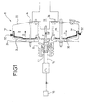
- a pneumatic booster 10 (FIG. 1) known comprises a housing 12 cooperating with a rod 14 of control, connected to the brake pedal 16, and with a rod 18 of thrust connected to the master cylinder 19 integral with the device braking, so that when the control rod 14 is moved by means of a command f transmitted by the pedal of brake, the servomotor moves the rod 18 by means of a thrust F greater than the intensity of the control f.
- the housing 12 comprises a cover 20, housing a pneumatic mechanism 21, and a cooperating cylinder 22 with the lid 20 sealingly.
- the internal volume of the housing 12 is divided into a first chamber 24, said chamber rear, and in a second chamber 26, said room before, at the means of a waterproof membrane 28 arranged to a rigid skirt 30 and secured to the housing 12.
- the pressure in the rear chambers 24 and before 26 is kept lower than the atmospheric pressure by means of a non-pumping device represent.
- the membrane 28 is in a position of rest as shown.
- the present invention results from the observation that the use of a membrane and a skirt arranged as previously described has many disadvantages.
- the present invention overcomes these disadvantages. It relates to a housing for pneumatic actuator of vehicle equipped with a rigid skirt and an elastic membrane connected at one end to the skirt and at a second end, housing, characterized in that the membrane is kept taut between the case and the skirt so independent of the position of the skirt.
- This invention has the advantage of reducing the length of elastic membrane required to seal the device since it does not require a fallback of the membrane to allow its movements. From then on, the weight and the cost of the housing are reduced.
- the end of the membrane connected to the skirt is attached to one end of this skirt. from then, the length of the used membrane is reduced again since the membrane does not cover the skirt.
- the skirt 204 metal is elongated to form the body of the device 214 tire, again reducing the weight of the device.
- the invention relates, in general, to a housing for pneumatic vehicle servomotor provided with a skirt rigid and connected elastic membrane, at a first end, the skirt and, at a second end, the housing, which is characterized in that the membrane is kept taut between the housing and the skirt independently of the position of the skirt.
- the membrane is, for example, attached to one end of the metallic skirt.
- the membrane comprises a elastic material, such as rubber.
- the membrane comprises fibers.
- the ends of the membrane can rotate, unwind and / or wrap depending on the moving the skirt.
- the metallic skirt is, for example, integral with the body of the pneumatic control device.
- the invention also relates to a pneumatic booster vehicle equipped with a housing comprising a rigid skirt and of an elastic membrane connected at a first end to the skirt and, at a second end, the housing, which is characterized in that the membrane is held taut between the casing and skirt independently of the position of the skirt.
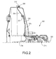
- FIG. 2 shows a servomotor 200 provided with a push rod 202 causing the movement of a skirt 204 rigid and a membrane 206 connected to the skirt 204 and the 208 housing of the booster.
- the membrane is maintained stretched between the case and the skirt independently of the position of the latter.
- the membrane 206 elastic deforms to stay stretched, that is to say substantially rectilinear during the movement of the skirt.
- the membrane 206 is made of material elastic material, such as rubber, reinforced with way to ensure thrust transmission due to the difference pressure between the rooms.
- the thrust transmitted by the membrane can represent a significant part of the thrust transmitted to the push rod 216, of the order of 25%.
- the metal skirt 204 can have dimensions smaller than the dimensions of a skirt used in the prior art, lightening the servomotor again.
- skirt 204 is elongated so as to forming the body of the pneumatic device 214, reducing the weight of the device.
- the assembly of the membrane with the skirt and the housing is easy because it is done by means of localized fixings that do not require a covering the membrane on the skirt.
- its ends 212 may be arranged in such a way that they rotate according to the movements of the skirt and / or such that the membrane unwinds or wraps so as to vary its length.
Landscapes
- Engineering & Computer Science (AREA)
- Transportation (AREA)
- Mechanical Engineering (AREA)
- Braking Systems And Boosters (AREA)
- Actuator (AREA)
Abstract
Description
La présente invention se rapporte à un boítier pour servomoteur pneumatique de véhicule et à un servomoteur muni de ce boítier.The present invention relates to a housing for pneumatic vehicle servomotor and to a servomotor provided with this case.
Un servomoteur est destiné à amplifier l'action exercée par le conducteur d'un véhicule sur une pédale de frein et à transmettre cette action amplifiée à un dispositif de freinage d'une (ou plusieurs) roue(s) du véhicule.A servomotor is intended to amplify the action exercised by the driver of a vehicle on a brake pedal and to transmit this amplified action to a device of braking one (or more) wheel (s) of the vehicle.
A cet effet, un servomoteur pneumatique 10 (figure 1)
connu comporte un boítier 12 coopérant avec une tige 14 de
commande, reliée à la pédale 16 de frein, et avec une tige 18 de
poussée reliée au maítre-cylindre 19 solidaire du dispositif de
freinage, de telle sorte que lorsque la tige 14 de commande est
déplacée au moyen d'une commande f transmise par la pédale de
frein, le servomoteur déplace la tige 18 au moyen d'une poussée
F d'intensité supérieure à l'intensité de la commande f.For this purpose, a pneumatic booster 10 (FIG. 1)
known comprises a
Pour cela, le boítier 12 comprend un couvercle 20,
logeant un mécanisme 21 pneumatique, et un cylindre 22 coopérant
avec le couvercle 20 de façon étanche. Le volume interne du
boítier 12 est divisé en une première chambre 24, dite chambre
arrière, et en une deuxième chambre 26, dite chambre avant, au
moyen d'une membrane 28 étanche agencée à une jupe rigide 30 et
solidaire du boítier 12.For this, the
Dans un premier temps, lorsqu'aucun freinage n'est
sollicité par le conducteur du véhicule, la pression dans les
chambres arrière 24 et avant 26 est maintenue inférieure à la
pression atmosphérique au moyen d'un dispositif de pompage non
représenté. Dans ce cas, la membrane 28 est dans une position de
repos telle que représentée.At first, when no braking is
requested by the driver of the vehicle, the pressure in the
Dans un deuxième temps, lorsque le conducteur du
véhicule appuie sur la pédale 16 de frein, une entrée d'air à
pression atmosphérique s'effectue dans la chambre arrière 24 et
entraíne le déplacement D de la membrane 28, de la jupe 30 et du
piston 18 solidaire de ces derniers, transmettant ainsi une
poussée F au maítre-cylindre 19.In a second step, when the driver of the
vehicle presses the
La présente invention résulte de la constatation que l'utilisation d'une membrane et d'une jupe agencées comme précédemment décrit présente de nombreux inconvénients.The present invention results from the observation that the use of a membrane and a skirt arranged as previously described has many disadvantages.
De fait, une longueur de membrane importante est utilisée pour recouvrir la jupe métallique et former un repli permettant le déplacement de cette membrane, ce qui augmente le coût et le poids du boítier.In fact, an important membrane length is used to cover the metal skirt and form a fold allowing the displacement of this membrane, which increases the cost and weight of the housing.
De plus, une opération complexe d'adhésion de la membrane sur la jupe doit être effectuée, ce qui accroít la complexité et le coût de production du boítier.Moreover, a complex operation of adhesion of the membrane on the skirt should be performed, which increases the complexity and the cost of production of the housing.
La présente invention remédie à ces inconvénients. Elle concerne un boítier pour servomoteur pneumatique de véhicule muni d'une jupe rigide et d'une membrane élastique reliée, à une première extrémité, à la jupe et, à une seconde extrémité, au boítier, caractérisé en ce que la membrane est maintenue tendue entre le boítier et la jupe de façon indépendante de la position de la jupe.The present invention overcomes these disadvantages. It relates to a housing for pneumatic actuator of vehicle equipped with a rigid skirt and an elastic membrane connected at one end to the skirt and at a second end, housing, characterized in that the membrane is kept taut between the case and the skirt so independent of the position of the skirt.
Cette invention présente l'avantage de réduire la longueur de membrane élastique requise pour assurer l'étanchéité du dispositif puisqu'elle ne requiert pas de repli de la membrane pour permettre ses déplacements. Dès lors, le poids et le coût du boítier sont réduits.This invention has the advantage of reducing the length of elastic membrane required to seal the device since it does not require a fallback of the membrane to allow its movements. From then on, the weight and the cost of the housing are reduced.
Dans une réalisation, l'extrémité de la membrane reliée à la jupe est fixée à une extrémité de cette jupe. Dès lors, la longueur de la membrane utilisée est à nouveau réduite puisque la membrane ne recouvre pas la jupe.In one embodiment, the end of the membrane connected to the skirt is attached to one end of this skirt. from then, the length of the used membrane is reduced again since the membrane does not cover the skirt.
En outre, un tel agencement ne requiert pas une opération complexe de recouvrement de la membrane sur la jupe, diminuant ainsi le coût de fabrication du boítier.In addition, such an arrangement does not require a complex operation of covering the membrane on the skirt, thus decreasing the cost of manufacturing the housing.
Par ailleurs, dans une réalisation, la jupe 204
métallique est allongée de façon à former le corps du dispositif
214 pneumatique, réduisant à nouveau le poids du dispositif.Moreover, in one embodiment, the
Ainsi, l'invention concerne, de façon générale, un boítier pour servomoteur pneumatique de véhicule muni d'une jupe rigide et d'une membrane élastique reliée, à une première extrémité, à la jupe et, à une seconde extrémité, au boítier, qui est caractérisé en ce que la membrane est maintenue tendue entre le boítier et la jupe de façon indépendante de la position de la jupe.Thus, the invention relates, in general, to a housing for pneumatic vehicle servomotor provided with a skirt rigid and connected elastic membrane, at a first end, the skirt and, at a second end, the housing, which is characterized in that the membrane is kept taut between the housing and the skirt independently of the position of the skirt.
La membrane est, par exemple, fixée à une extrémité de la jupe métallique.The membrane is, for example, attached to one end of the metallic skirt.
Selon une réalisation, la membrane comprend un matériau élastique, tel que du caoutchouc.In one embodiment, the membrane comprises a elastic material, such as rubber.
Dans une réalisation, la membrane comprend des fibres.In one embodiment, the membrane comprises fibers.
Selon une réalisation, les extrémités de la membrane peuvent pivoter, se dérouler et/ou s'enrouler en fonction du déplacement de la jupe.In one embodiment, the ends of the membrane can rotate, unwind and / or wrap depending on the moving the skirt.
La jupe métallique est, par exemple, solidaire du corps du dispositif pneumatique de commande.The metallic skirt is, for example, integral with the body of the pneumatic control device.
L'invention concerne aussi un servomoteur pneumatique de véhicule muni d'un boítier comprenant une jupe rigide et d'une membrane élastique reliée, à une première extrémité, à la jupe et, à une seconde extrémité, au boítier, qui est caractérisé en ce que la membrane est maintenue tendue entre le boítier et la jupe de façon indépendante de la position de la jupe.The invention also relates to a pneumatic booster vehicle equipped with a housing comprising a rigid skirt and of an elastic membrane connected at a first end to the skirt and, at a second end, the housing, which is characterized in that the membrane is held taut between the casing and skirt independently of the position of the skirt.
D'autres caractéristiques et avantages de l'invention apparaítront avec la description ci-dessous, à titre non limitatif, en référence aux dessins ci-annexés sur lesquels :
- la figure 1 représente une vue en coupe transversale d'un servomoteur connu ;
- la figure 2 représente une vue transversale d'un servomoteur muni d'un boítier conforme à l'invention.
- Figure 1 shows a cross-sectional view of a known servomotor;
- FIG. 2 represents a transverse view of a booster fitted with a housing according to the invention.
Sur la figure 2 est représenté un servomoteur 200 muni
d'une tige 202 de poussée entraínant le déplacement d'une jupe
204 rigide et d'une membrane 206 reliée à la jupe 204 et au
boítier 208 du servomoteur.FIG. 2 shows a
Conformément à l'invention, la membrane est maintenue tendue entre le boítier et la jupe de façon indépendante de la position de cette dernière.According to the invention, the membrane is maintained stretched between the case and the skirt independently of the position of the latter.
Ainsi, lorsque la jupe 204 se déplace sous l'effet de
l'accroissement de pression dans la chambre arrière 210 du
servomoteur, la membrane 206 élastique se déforme pour rester
tendue, c'est-à-dire de façon sensiblement rectiligne lors du
mouvement de la jupe.Thus, when the
Pour cela, la membrane 206 est fabriquée en matière
élastique, telle que du caoutchouc, renforcée par des fibres de
façon à assurer une transmission de poussée due à la différence
de pression entre les chambres.For this, the
De fait, la poussée transmise par la membrane peut
représenter une part importante de la poussée transmise à la
tige 216 de poussée, de l'ordre de 25 %.In fact, the thrust transmitted by the membrane can
represent a significant part of the thrust transmitted to the
Dès lors, la jupe 204 métallique peut avoir des
dimensions inférieures aux dimensions d'une jupe utilisée dans
l'art antérieur, allégeant à nouveau le servomoteur.Therefore, the
Par ailleurs, la jupe 204 est allongée de façon à
former le corps du dispositif 214 pneumatique, réduisant le
poids du dispositif. Furthermore, the
Il convient de signaler que l'assemblage de la membrane avec la jupe et le boítier est aisé car il est effectué au moyen de fixations localisées ne nécessitant pas un recouvrement de la membrane sur la jupe.It should be noted that the assembly of the membrane with the skirt and the housing is easy because it is done by means of localized fixings that do not require a covering the membrane on the skirt.
De façon à maintenir la membrane 206 tendue, ses
extrémités 212 peuvent être agencées de telle sorte qu'elles
pivotent selon les déplacements de la jupe et/ou de telle sorte
que la membrane se déroule ou s'enroule de façon à faire varier
sa longueur.In order to keep the
Claims (7)
Priority Applications (1)
| Application Number | Priority Date | Filing Date | Title |
|---|---|---|---|
| PL04029434T PL1548336T3 (en) | 2003-12-24 | 2004-12-13 | Housing for a pneumatic brake booster for a vehicle and brake booster comprising such a housing |
Applications Claiming Priority (2)
| Application Number | Priority Date | Filing Date | Title |
|---|---|---|---|
| FR0315509 | 2003-12-24 | ||
| FR0315509A FR2864505B1 (en) | 2003-12-24 | 2003-12-24 | HOUSING FOR A PNEUMATIC SERVOMOTOR OF A VEHICLE AND A SERVOMOTOR PROVIDED WITH SAID HOUSING |
Publications (2)
| Publication Number | Publication Date |
|---|---|
| EP1548336A1 true EP1548336A1 (en) | 2005-06-29 |
| EP1548336B1 EP1548336B1 (en) | 2006-08-30 |
Family
ID=34531366
Family Applications (1)
| Application Number | Title | Priority Date | Filing Date |
|---|---|---|---|
| EP04029434A Expired - Lifetime EP1548336B1 (en) | 2003-12-24 | 2004-12-13 | Housing for a pneumatic brake booster for a vehicle and brake booster comprising such a housing |
Country Status (6)
| Country | Link |
|---|---|
| EP (1) | EP1548336B1 (en) |
| AT (1) | ATE338231T1 (en) |
| DE (1) | DE602004002185T2 (en) |
| ES (1) | ES2268569T3 (en) |
| FR (1) | FR2864505B1 (en) |
| PL (1) | PL1548336T3 (en) |
Citations (3)
| Publication number | Priority date | Publication date | Assignee | Title |
|---|---|---|---|---|
| FR1547451A (en) * | 1966-07-12 | 1968-11-29 | Goodrich Co B F | Diaphragm for braking device |
| US4936635A (en) * | 1988-04-11 | 1990-06-26 | Jidosha Kiki Co., Ltd. | Brake booster |
| WO2003037693A1 (en) * | 2001-10-29 | 2003-05-08 | Hutchinson | Device constituting a mobile and sealing partition, in particular for a motor vehicle braking circuit brake booster, and brake booster equipped therewith |
-
2003
- 2003-12-24 FR FR0315509A patent/FR2864505B1/en not_active Expired - Fee Related
-
2004
- 2004-12-13 EP EP04029434A patent/EP1548336B1/en not_active Expired - Lifetime
- 2004-12-13 DE DE602004002185T patent/DE602004002185T2/en not_active Expired - Lifetime
- 2004-12-13 AT AT04029434T patent/ATE338231T1/en not_active IP Right Cessation
- 2004-12-13 ES ES04029434T patent/ES2268569T3/en not_active Expired - Lifetime
- 2004-12-13 PL PL04029434T patent/PL1548336T3/en unknown
Patent Citations (3)
| Publication number | Priority date | Publication date | Assignee | Title |
|---|---|---|---|---|
| FR1547451A (en) * | 1966-07-12 | 1968-11-29 | Goodrich Co B F | Diaphragm for braking device |
| US4936635A (en) * | 1988-04-11 | 1990-06-26 | Jidosha Kiki Co., Ltd. | Brake booster |
| WO2003037693A1 (en) * | 2001-10-29 | 2003-05-08 | Hutchinson | Device constituting a mobile and sealing partition, in particular for a motor vehicle braking circuit brake booster, and brake booster equipped therewith |
Also Published As
| Publication number | Publication date |
|---|---|
| ATE338231T1 (en) | 2006-09-15 |
| FR2864505A1 (en) | 2005-07-01 |
| EP1548336B1 (en) | 2006-08-30 |
| FR2864505B1 (en) | 2006-03-17 |
| DE602004002185T2 (en) | 2007-07-19 |
| ES2268569T3 (en) | 2007-03-16 |
| DE602004002185D1 (en) | 2006-10-12 |
| PL1548336T3 (en) | 2007-01-31 |
Similar Documents
| Publication | Publication Date | Title |
|---|---|---|
| EP0341101B1 (en) | Servo brake booster | |
| FR2489437A1 (en) | FORCE AMPLIFIER CONTROLLING MECHANICALLY, ESPECIALLY FOR HYDRAULIC BRAKING SYSTEMS | |
| FR2756240A1 (en) | ASSISTED BRAKING DEVICE WITH A VARIABLE ASSISTANCE RATIO AND REDUCED HYSTERESIS | |
| EP0340059B1 (en) | Servo brake booster with an adjustable threshold value | |
| WO1994006660A1 (en) | Pneumatic servomotor | |
| EP0779868B1 (en) | Protected-travel improved-safety power-assisted brake device | |
| EP1548336B1 (en) | Housing for a pneumatic brake booster for a vehicle and brake booster comprising such a housing | |
| EP0368691A1 (en) | Control device of a servo motor, especially for a motor vehicle brake system | |
| EP1346894B1 (en) | Pneumatic brake servo with improved seals | |
| EP1439991B1 (en) | Device constituting a mobile and sealing partition, in particular for a motor vehicle braking circuit brake booster, and brake booster equipped therewith | |
| EP0814988B1 (en) | Pneumatic reaction-type pneumatic servo | |
| EP0681538B1 (en) | Pneumatic servo device | |
| EP0395461B1 (en) | Vacuum-assisted servo motor | |
| FR2727923A1 (en) | PNEUMATIC BRAKE ASSIST SERVO MOTOR WITH SILENT OPERATION | |
| EP1362756A1 (en) | Pneumatic brake booster with reduced noise | |
| WO2002046012A1 (en) | Brake booster for motor vehicle | |
| FR2864498A1 (en) | Pneumatic servomotor`s case for vehicle, includes elastic membrane with two ends fixed to respective chambers, such that metallic skirt slides along membrane according to membrane`s movements | |
| EP1597127A1 (en) | Brake control device | |
| EP1325853A2 (en) | Pneumatic brake servo with reduced reaction | |
| FR2905653A1 (en) | Pneumatic servomotor for assisting braking of motor vehicle, has balancing valve re-establishing, in chambers, pressure corresponding to rest position of servomotor when admission and balancing check valves are closed in rest position | |
| FR2825056A1 (en) | AIR VARIABLE JUMP HEIGHT BRAKE ASSIST MOTOR | |
| FR2609675A1 (en) | HYDRAULIC ACTUATING DEVICE OF A BRAKING SYSTEM AND / OR A CLUTCH OF A MOTOR VEHICLE | |
| FR2867140A1 (en) | Pneumatic actuator for brake master cylinder, has piston with piezoelectric actuator increasing length of bush to vary position of front side of piston to apply braking force along skip distance greater than determined skip distance | |
| FR2837453A1 (en) | Pneumatic brake assistance servomotor has seal between working and low-pressure chambers formed on inner and outer edges of separating skirt | |
| WO2002087946A2 (en) | Servomotor comprising a jamming key |
Legal Events
| Date | Code | Title | Description |
|---|---|---|---|
| PUAI | Public reference made under article 153(3) epc to a published international application that has entered the european phase |
Free format text: ORIGINAL CODE: 0009012 |
|
| AK | Designated contracting states |
Kind code of ref document: A1 Designated state(s): AT BE BG CH CY CZ DE DK EE ES FI FR GB GR HU IE IS IT LI LT LU MC NL PL PT RO SE SI SK TR |
|
| AX | Request for extension of the european patent |
Extension state: AL BA HR LV MK YU |
|
| 17P | Request for examination filed |
Effective date: 20051229 |
|
| AKX | Designation fees paid |
Designated state(s): AT BE BG CH CY CZ DE DK EE ES FI FR GB GR HU IE IS IT LI LT LU MC NL PL PT RO SE SI SK TR |
|
| GRAP | Despatch of communication of intention to grant a patent |
Free format text: ORIGINAL CODE: EPIDOSNIGR1 |
|
| GRAS | Grant fee paid |
Free format text: ORIGINAL CODE: EPIDOSNIGR3 |
|
| GRAA | (expected) grant |
Free format text: ORIGINAL CODE: 0009210 |
|
| AK | Designated contracting states |
Kind code of ref document: B1 Designated state(s): AT BE BG CH CY CZ DE DK EE ES FI FR GB GR HU IE IS IT LI LT LU MC NL PL PT RO SE SI SK TR |
|
| PG25 | Lapsed in a contracting state [announced via postgrant information from national office to epo] |
Ref country code: CZ Free format text: LAPSE BECAUSE OF FAILURE TO SUBMIT A TRANSLATION OF THE DESCRIPTION OR TO PAY THE FEE WITHIN THE PRESCRIBED TIME-LIMIT Effective date: 20060830 Ref country code: AT Free format text: LAPSE BECAUSE OF FAILURE TO SUBMIT A TRANSLATION OF THE DESCRIPTION OR TO PAY THE FEE WITHIN THE PRESCRIBED TIME-LIMIT Effective date: 20060830 Ref country code: SI Free format text: LAPSE BECAUSE OF FAILURE TO SUBMIT A TRANSLATION OF THE DESCRIPTION OR TO PAY THE FEE WITHIN THE PRESCRIBED TIME-LIMIT Effective date: 20060830 Ref country code: SK Free format text: LAPSE BECAUSE OF FAILURE TO SUBMIT A TRANSLATION OF THE DESCRIPTION OR TO PAY THE FEE WITHIN THE PRESCRIBED TIME-LIMIT Effective date: 20060830 Ref country code: IS Free format text: LAPSE BECAUSE OF FAILURE TO SUBMIT A TRANSLATION OF THE DESCRIPTION OR TO PAY THE FEE WITHIN THE PRESCRIBED TIME-LIMIT Effective date: 20060830 Ref country code: RO Free format text: LAPSE BECAUSE OF FAILURE TO SUBMIT A TRANSLATION OF THE DESCRIPTION OR TO PAY THE FEE WITHIN THE PRESCRIBED TIME-LIMIT Effective date: 20060830 Ref country code: GB Free format text: LAPSE BECAUSE OF FAILURE TO SUBMIT A TRANSLATION OF THE DESCRIPTION OR TO PAY THE FEE WITHIN THE PRESCRIBED TIME-LIMIT Effective date: 20060830 Ref country code: IE Free format text: LAPSE BECAUSE OF FAILURE TO SUBMIT A TRANSLATION OF THE DESCRIPTION OR TO PAY THE FEE WITHIN THE PRESCRIBED TIME-LIMIT Effective date: 20060830 Ref country code: FI Free format text: LAPSE BECAUSE OF FAILURE TO SUBMIT A TRANSLATION OF THE DESCRIPTION OR TO PAY THE FEE WITHIN THE PRESCRIBED TIME-LIMIT Effective date: 20060830 Ref country code: NL Free format text: LAPSE BECAUSE OF FAILURE TO SUBMIT A TRANSLATION OF THE DESCRIPTION OR TO PAY THE FEE WITHIN THE PRESCRIBED TIME-LIMIT Effective date: 20060830 Ref country code: LT Free format text: LAPSE BECAUSE OF FAILURE TO SUBMIT A TRANSLATION OF THE DESCRIPTION OR TO PAY THE FEE WITHIN THE PRESCRIBED TIME-LIMIT Effective date: 20060830 |
|
| REG | Reference to a national code |
Ref country code: GB Ref legal event code: FG4D Free format text: NOT ENGLISH |
|
| REG | Reference to a national code |
Ref country code: CH Ref legal event code: EP |
|
| REG | Reference to a national code |
Ref country code: IE Ref legal event code: FG4D Free format text: LANGUAGE OF EP DOCUMENT: FRENCH |
|
| REF | Corresponds to: |
Ref document number: 602004002185 Country of ref document: DE Date of ref document: 20061012 Kind code of ref document: P |
|
| PG25 | Lapsed in a contracting state [announced via postgrant information from national office to epo] |
Ref country code: BG Free format text: LAPSE BECAUSE OF FAILURE TO SUBMIT A TRANSLATION OF THE DESCRIPTION OR TO PAY THE FEE WITHIN THE PRESCRIBED TIME-LIMIT Effective date: 20061130 Ref country code: SE Free format text: LAPSE BECAUSE OF FAILURE TO SUBMIT A TRANSLATION OF THE DESCRIPTION OR TO PAY THE FEE WITHIN THE PRESCRIBED TIME-LIMIT Effective date: 20061130 Ref country code: DK Free format text: LAPSE BECAUSE OF FAILURE TO SUBMIT A TRANSLATION OF THE DESCRIPTION OR TO PAY THE FEE WITHIN THE PRESCRIBED TIME-LIMIT Effective date: 20061130 |
|
| PG25 | Lapsed in a contracting state [announced via postgrant information from national office to epo] |
Ref country code: BE Free format text: LAPSE BECAUSE OF NON-PAYMENT OF DUE FEES Effective date: 20061231 Ref country code: MC Free format text: LAPSE BECAUSE OF NON-PAYMENT OF DUE FEES Effective date: 20061231 |
|
| REG | Reference to a national code |
Ref country code: PL Ref legal event code: T3 |
|
| PG25 | Lapsed in a contracting state [announced via postgrant information from national office to epo] |
Ref country code: PT Free format text: LAPSE BECAUSE OF FAILURE TO SUBMIT A TRANSLATION OF THE DESCRIPTION OR TO PAY THE FEE WITHIN THE PRESCRIBED TIME-LIMIT Effective date: 20070206 |
|
| NLV1 | Nl: lapsed or annulled due to failure to fulfill the requirements of art. 29p and 29m of the patents act | ||
| REG | Reference to a national code |
Ref country code: ES Ref legal event code: FG2A Ref document number: 2268569 Country of ref document: ES Kind code of ref document: T3 |
|
| GBV | Gb: ep patent (uk) treated as always having been void in accordance with gb section 77(7)/1977 [no translation filed] |
Effective date: 20060830 |
|
| REG | Reference to a national code |
Ref country code: IE Ref legal event code: FD4D |
|
| PLBE | No opposition filed within time limit |
Free format text: ORIGINAL CODE: 0009261 |
|
| STAA | Information on the status of an ep patent application or granted ep patent |
Free format text: STATUS: NO OPPOSITION FILED WITHIN TIME LIMIT |
|
| 26N | No opposition filed |
Effective date: 20070531 |
|
| BERE | Be: lapsed |
Owner name: ROBERT BOSCH G.M.B.H. Effective date: 20061231 |
|
| PG25 | Lapsed in a contracting state [announced via postgrant information from national office to epo] |
Ref country code: GR Free format text: LAPSE BECAUSE OF FAILURE TO SUBMIT A TRANSLATION OF THE DESCRIPTION OR TO PAY THE FEE WITHIN THE PRESCRIBED TIME-LIMIT Effective date: 20061201 |
|
| PG25 | Lapsed in a contracting state [announced via postgrant information from national office to epo] |
Ref country code: EE Free format text: LAPSE BECAUSE OF FAILURE TO SUBMIT A TRANSLATION OF THE DESCRIPTION OR TO PAY THE FEE WITHIN THE PRESCRIBED TIME-LIMIT Effective date: 20060830 |
|
| PG25 | Lapsed in a contracting state [announced via postgrant information from national office to epo] |
Ref country code: HU Free format text: LAPSE BECAUSE OF FAILURE TO SUBMIT A TRANSLATION OF THE DESCRIPTION OR TO PAY THE FEE WITHIN THE PRESCRIBED TIME-LIMIT Effective date: 20070301 Ref country code: LU Free format text: LAPSE BECAUSE OF NON-PAYMENT OF DUE FEES Effective date: 20061213 Ref country code: TR Free format text: LAPSE BECAUSE OF FAILURE TO SUBMIT A TRANSLATION OF THE DESCRIPTION OR TO PAY THE FEE WITHIN THE PRESCRIBED TIME-LIMIT Effective date: 20060830 |
|
| PG25 | Lapsed in a contracting state [announced via postgrant information from national office to epo] |
Ref country code: CY Free format text: LAPSE BECAUSE OF FAILURE TO SUBMIT A TRANSLATION OF THE DESCRIPTION OR TO PAY THE FEE WITHIN THE PRESCRIBED TIME-LIMIT Effective date: 20060830 |
|
| REG | Reference to a national code |
Ref country code: CH Ref legal event code: PL |
|
| PG25 | Lapsed in a contracting state [announced via postgrant information from national office to epo] |
Ref country code: CH Free format text: LAPSE BECAUSE OF NON-PAYMENT OF DUE FEES Effective date: 20081231 Ref country code: LI Free format text: LAPSE BECAUSE OF NON-PAYMENT OF DUE FEES Effective date: 20081231 |
|
| PGFP | Annual fee paid to national office [announced via postgrant information from national office to epo] |
Ref country code: FR Payment date: 20131213 Year of fee payment: 10 |
|
| REG | Reference to a national code |
Ref country code: FR Ref legal event code: ST Effective date: 20150831 |
|
| PG25 | Lapsed in a contracting state [announced via postgrant information from national office to epo] |
Ref country code: FR Free format text: LAPSE BECAUSE OF NON-PAYMENT OF DUE FEES Effective date: 20141231 |
|
| PGFP | Annual fee paid to national office [announced via postgrant information from national office to epo] |
Ref country code: DE Payment date: 20160224 Year of fee payment: 12 |
|
| PGFP | Annual fee paid to national office [announced via postgrant information from national office to epo] |
Ref country code: PL Payment date: 20161130 Year of fee payment: 13 Ref country code: IT Payment date: 20161220 Year of fee payment: 13 Ref country code: ES Payment date: 20161221 Year of fee payment: 13 |
|
| REG | Reference to a national code |
Ref country code: DE Ref legal event code: R119 Ref document number: 602004002185 Country of ref document: DE |
|
| PG25 | Lapsed in a contracting state [announced via postgrant information from national office to epo] |
Ref country code: DE Free format text: LAPSE BECAUSE OF NON-PAYMENT OF DUE FEES Effective date: 20170701 |
|
| PG25 | Lapsed in a contracting state [announced via postgrant information from national office to epo] |
Ref country code: IT Free format text: LAPSE BECAUSE OF NON-PAYMENT OF DUE FEES Effective date: 20171213 |
|
| PG25 | Lapsed in a contracting state [announced via postgrant information from national office to epo] |
Ref country code: PL Free format text: LAPSE BECAUSE OF NON-PAYMENT OF DUE FEES Effective date: 20171213 |
|
| REG | Reference to a national code |
Ref country code: ES Ref legal event code: FD2A Effective date: 20190703 |
|
| PG25 | Lapsed in a contracting state [announced via postgrant information from national office to epo] |
Ref country code: ES Free format text: LAPSE BECAUSE OF NON-PAYMENT OF DUE FEES Effective date: 20171214 |