EP1548333B1 - Fluid actuated shift device of a transmission - Google Patents
Fluid actuated shift device of a transmission Download PDFInfo
- Publication number
- EP1548333B1 EP1548333B1 EP20040026109 EP04026109A EP1548333B1 EP 1548333 B1 EP1548333 B1 EP 1548333B1 EP 20040026109 EP20040026109 EP 20040026109 EP 04026109 A EP04026109 A EP 04026109A EP 1548333 B1 EP1548333 B1 EP 1548333B1
- Authority
- EP
- European Patent Office
- Prior art keywords
- gearshift
- pressure
- rod
- bore
- pressure medium
- Prior art date
- Legal status (The legal status is an assumption and is not a legal conclusion. Google has not performed a legal analysis and makes no representation as to the accuracy of the status listed.)
- Expired - Fee Related
Links
Images
Classifications
-
- F—MECHANICAL ENGINEERING; LIGHTING; HEATING; WEAPONS; BLASTING
- F16—ENGINEERING ELEMENTS AND UNITS; GENERAL MEASURES FOR PRODUCING AND MAINTAINING EFFECTIVE FUNCTIONING OF MACHINES OR INSTALLATIONS; THERMAL INSULATION IN GENERAL
- F16H—GEARING
- F16H63/00—Control outputs from the control unit to change-speed- or reversing-gearings for conveying rotary motion or to other devices than the final output mechanism
- F16H63/02—Final output mechanisms therefor; Actuating means for the final output mechanisms
- F16H63/30—Constructional features of the final output mechanisms
- F16H63/3023—Constructional features of the final output mechanisms the final output mechanisms comprising elements moved by fluid pressure
-
- F—MECHANICAL ENGINEERING; LIGHTING; HEATING; WEAPONS; BLASTING
- F16—ENGINEERING ELEMENTS AND UNITS; GENERAL MEASURES FOR PRODUCING AND MAINTAINING EFFECTIVE FUNCTIONING OF MACHINES OR INSTALLATIONS; THERMAL INSULATION IN GENERAL
- F16H—GEARING
- F16H63/00—Control outputs from the control unit to change-speed- or reversing-gearings for conveying rotary motion or to other devices than the final output mechanism
- F16H63/02—Final output mechanisms therefor; Actuating means for the final output mechanisms
- F16H63/30—Constructional features of the final output mechanisms
- F16H2063/3079—Shift rod assembly, e.g. supporting, assembly or manufacturing of shift rails or rods; Special details thereof
-
- F—MECHANICAL ENGINEERING; LIGHTING; HEATING; WEAPONS; BLASTING
- F16—ENGINEERING ELEMENTS AND UNITS; GENERAL MEASURES FOR PRODUCING AND MAINTAINING EFFECTIVE FUNCTIONING OF MACHINES OR INSTALLATIONS; THERMAL INSULATION IN GENERAL
- F16H—GEARING
- F16H59/00—Control inputs to control units of change-speed-, or reversing-gearings for conveying rotary motion
- F16H59/68—Inputs being a function of gearing status
- F16H59/70—Inputs being a function of gearing status dependent on the ratio established
Definitions
- the invention relates to a fluid-operated switching device of a variable-speed transmission according to the preamble of claim 1.
- the switching element may be either a shift fork or a shift finger. Most of the shift rod is moved between three axially adjacent positions, the axially outer positions correspond to an engaged gear and the middle position of a neutral position. As a pressure medium, a suitable hydraulic fluid or compressed air would be conceivable. Furthermore, it is quite conceivable to move other gear elements, such as a gear for switching a reverse gear in this way.
- a fluid-operated switching device of a variable-speed transmission is known from DE 34 35 160 C2.
- the shift rod On the shift rod center a shift fork is attached.
- the shift rod carries at its two axial ends depending on a piston and is mounted axially displaceably in cylindrical recesses on opposite sides of the transmission housing.
- a pressure chamber Depending on a piston together with a cylindrical recess a pressure chamber.
- Each pressure chamber communicates by means of a pressure medium line with a pressure medium reservoir, wherein the pressure medium lines are introduced in opposite walls of the transmission housing.
- this spring element has the task of completing the switching process or returning the switch rod or rods to the original position.
- This spring element has the task of completing the switching process or returning the switch rod or rods to the original position.
- the large number of required sealing points and a spatial separation of the pressure medium lines in the transmission housing is present.
- the introduction of the pressure medium lines in opposite walls of the transmission housing is a complex and costly operation.
- the invention is therefore an object of the invention to provide a fluid-operated switching device of a variable speed transmission, for which the cost and effort in the processing of the transmission housing can be lowered.
- the object is achieved by the features of claim 1; the shift rod is at least partially hollow and at least the first pressure chamber communicates via the hollow running part of the shift rod with the associated pressure medium line.
- the shift rod is at least partially provided with a bore, wherein at least one axial end of the shift rod, which is mounted in one of the pressure chambers, is made open.
- a pressure medium line communicates with the bore of the shift rod.
- annular body is mounted on the shift rod in the region of the axial ends.
- the annular body can be connected non-positively or by means of welding, riveting or adhesive connection with the shift rod.
- the second pressure medium line opens directly into the second pressure chamber.
- the first pressure medium line opens into a cavity, which adjoins the second pressure chamber.
- the shift rod is provided with an axial first bore, wherein the bore extends from one axial end of the shift rod to the other axial end. Furthermore, it is provided that the cavity communicates with the bore of the shift rod.
- the pressure medium line run closely adjacent in a wall of the transmission housing.
- the pressure medium lines open into adjacent cavities.
- the first cavity is connected via the through hole in the shift rod with the first pressure chamber at the side facing away from the cavities axial end of the shift rod.
- Pressure medium can reach this way in the first pressure chamber and exert an axially directed force on the shift rod or an end face of the annular body.
- the second cavity into which the other pressure medium line opens is the second pressure chamber, in which the pressure medium can also exert an axially directed force on the switching rod or an end face of the annular body.
- Advantageous effect in this embodiment is that only one gear housing half is to be provided with pressure medium lines, whereby the cost and the cost of manufacturing the gear housing significantly decrease.
- an at least partially cylindrical executed hydraulic insert is mounted in the second pressure chamber with a cylinder bore through the second bore, wherein the first axial end in the hollow running shift rod and the second axial end in a transmission housing bore in the bottom of the second pressure chamber engages, the hydraulic insert separates the cavity of the second pressure chamber and the joints between the hydraulic insert and the shift rod and between the hydraulic insert and the bottom of the second pressure chamber are pressure-tight.
- the bottom of the first cylinder is provided with a gear housing bore.
- the two pressure medium lines open into the transmission housing bore, wherein the pressure medium lines are arranged offset from one another in the axial direction of the shift rod.
- An at least partially cylindrical executed hydraulic insert is inserted into this bore.
- the hydraulic insert is designed such that one of its cylindrical lateral surfaces in the gear housing bore engages and forms a pressure-tight, annular contact with the transmission housing at a position between the pressure medium lines.
- the outer diameter of the hydraulic insert in the region of the first pressure medium line is made smaller, whereby a cavity in the form of an annular groove is formed, in which the first pressure medium line opens.
- the hydraulic insert is provided with a extending in the axial direction of the shift rod cylindrical portion, which engages in the bore of the shift rod.
- the outer diameter of this cylindrical portion is adapted to the inner diameter of the bore of the shift rod.
- a sealing ring is provided on the outer circumferential surface of this cylindrical portion, which seals the contact surface to the shift rod bore.
- a bore is introduced, which extends from its end located in the shift rod to the region of the annular groove.
- the groove and the bore are connected via radially extending within the hydraulic insert piercing holes.
- the first pressure medium line communicates via the groove, the tap holes, the bore within the hydraulic insert and the bore within the shift rod with the first pressure chamber, which is bounded by a first cylinder and the end face of the shift rod or an end face of the annular body.
- the second pressure medium line opens directly into the second cylinder, which is now limited by the end face of the shift rod or an end face of the annular body, the lateral surface of the cylinder and the hydraulic insert.
- the first pressure chamber is provided with a longitudinal stop for the shift rod or the annular body.
- a longitudinal stop for the shift rod or the annular body This can be carried out by means of a depression in the bottom of the first pressure chamber.
- the trough is arranged in the region of the first bore of the at least partially hollow switching rod and extends in the radial direction at least partially beyond the boundary of the bore.
- a longitudinal stop is also provided in the second pressure chamber.
- the longitudinal stops can of course also be formed by protruding wedges, annular spacers or the like in the cylinder jacket surfaces or cylinder bottoms. It is also possible that the longitudinal stop of the second pressure chamber is formed integrally with the hydraulic insert.
- position sensors are mounted on the cylindrical portion of the hydraulic insert and the first bore of the shift rod.
- a switching element is a shift finger or a shift fork
- a pressure medium a hydraulic fluid or compressed air is provided.
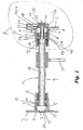
- FIG. 1 shows a switching device 1 according to the invention.
- a transmission housing 2 two opposing cylinders 3 and 4, each with an inner cylindrical lateral surface 5 and 6 and in each case a bottom 7 and 8 are formed.
- the successive facing faces of the cylinders 3 and 4 are made open.
- a shift rod 9 engages with one of its axial ends through the open end faces in one of the cylinders 3 and 4 a.
- On the axial ends of the shift rod 9 each have an annular body 11 and 12 is attached.
- the cylindrical body 11 and 12 are made for example of plastic or a suitable metal, or a metal alloy.
- the shift rod 9 is provided with a continuous first bore 10.
- the outer cylindrical lateral surfaces 13 of the annular bodies 11 and 12 abuts against the respective inner circumferential surface 5 and 6 of the cylinders 3 and 4.
- the shift rod 9 is arranged axially displaceably in the cylinders 3 and 4, wherein either the inner lateral surfaces 5 and 6 or the outer lateral surfaces 13 of the annular body 11 and 12 is provided with a suitable plastic or metal layer in order to minimize the friction during axial displacement of the shift rod 9. It is also conceivable that the shift rod 9 via radial linear bearings 32, which run in sleeves 40, primarily steel sleeves, is mounted linearly displaceable and rotatable in the cylinders 3 and 4.
- the connection between the annular bodies 5 and the shift rod 9 can be made for example by adhesion or welded joints.
- On the outer lateral surfaces 13 of the annular body 11 and 12 sealing ring 16 are provided which separate the interior of the cylinder 3 and 4 pressure-tight from the outside.
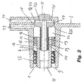
- the shift rod 9 is guided at its axial end, which engages in the second cylinder 4 axially displaceable on a cylindrical portion 14 of a hydraulic insert 15. (Figure 2).
- the cylindrical portion 14 engages in the first bore 10 of the shift rod 9 a.
- the outer diameter of the cylindrical portion 14 is adapted to the inner diameter of the first bore 10.
- a sealing ring 16 is provided in the outer circumferential surface of the cylindrical portion 14, which produces a pressure-tight connection between the two cylindrical surfaces.
- the cylindrical portion 14 of the hydraulic insert 15 protrudes from the first bore 10 of the shift rod 9 out to the bottom 8 of the second cylinder 4.
- a gear housing bore 17 is provided, into which the hydraulic insert 15 protrudes.
- the gear housing bore 17 is designed such that the hydraulic insert 15 in the radial direction pressure-sealed with the gear housing bore 17. This connection can be made for example by means of adhesion or welded joints. On the side facing away from the second cylinder 4 side of the junction of the diameter of the hydraulic insert 15 is smaller than at the junction itself executed. This creates a pressure-tight isolated from the second cylinder 4 cavity 34 in the form of a first annular groove 18.
- the hydraulic insert 15 is provided with a second bore 19. This extends in the axial direction from the cylindrical portion 14 into the region of the hydraulic insert 15, which of the first annular groove 18 is surrounded.
- the second bore 19 is connected by means of tap holes 20 with the first annular groove 18.
- a first and a second pressure medium line 21 and 22 are provided in the wall of the transmission housing 2, which adjoins the second cylinder 4.
- the first and second pressure medium lines 21 and 22 extend adjacent in the wall of the transmission housing 2, which adjoins the second cylinder 4.
- the first pressure medium line 21 is connected to the first annular groove 18.
- the second pressure medium line 22 is connected to the second cylinder 4.
- the first cylinder 3, the annular body 11, the shift rod 9 and the inner wall of the second bore 19 of the hydraulic insert 15 limit the volume of the first pressure chamber 23.
- the second cylinder 4, the hydraulic insert 15, the shift rod 9 and the annular body 12 form a sealed volume of the second pressure chamber 24.
- a pressure medium is supplied via the second pressure medium line 22
- This force leads to an axial displacement of the shift rod 9 in the direction of the first cylinder 3, whereby a mounted on the shift rod 9 switching element 25 is also displaced.
- a pressure medium is supplied via the first pressure medium line 21, this passes via the first annular groove 18, the tap holes 20, the second bore 19 of the hydraulic insert 15 and the first bore 10 of the shift rod 9 in the second pressure chamber 24.
- the supplied pressure medium acts on the end surfaces the shift rod 9 and the annular body 7 with a force, whereby the shift rod 9 and thus the switching element 25 in the axial direction to the second cylinder 4 is moved.
- the switching element 25 may be, for example, a shift fork or a shift finger.
- the shift rod 9 is rotatably mounted in the cylinders 3 and 4.
- FIG. 1 shows a trough 27 which is designed such that it covers at least part of the surface of the first bore 10 and the end face of the shift rod 9.
- the longitudinal stop 26 is realized by different diameters of the bottom 8 of the second cylinder 4 and the second bore 19.
- the diameter of the second bore 19 is made smaller than the inner diameter of the second cylinder 4.
- the outer diameter of the hydraulic insert 15 is made smaller in this area than the inner diameter of the gear housing bore 17, whereby a second annular groove 28 is formed.
- the shift rod 9 is in a position in which it rests against the bottom 8 of the second cylinder 4, the pressure medium can pass through the second pressure medium line 22 in the second annular groove 28 and the shift rod 9 act on an axial force.
- the shift rod 9 is displaced in the axial direction on the cylindrical portion 14 of the hydraulic insert 15.
- position sensors 29, such as induction change, reverberation or Hall sensors, are mounted in the outer surface of the cylindrical portion 14.
- a suitable hydraulic fluid or compressed air can be used as pressure medium.
- the switching element can be realized by a shift fork or a shift finger.
Description
Die Erfindung betrifft eine druckmittelbetätigte Schaltvorrichtung eines Stufenwechselgetriebes nach dem Oberbegriff des Anspruchs 1.The invention relates to a fluid-operated switching device of a variable-speed transmission according to the preamble of claim 1.
Es sind druckmittelbetätigte Schaltvorrichtungen eines Stufenwechselgetriebes bekannt, bei denen die Enden einer Schaltstange bzw. einer Schaltschiene kolbenförmig ausgebildet sind. Die Kolben sind axial verschiebbar in Zylindern, die im Getriebegehäuse ausgebildet sind, geführt. Die Kolben und die Zylinder bilden Druckkammern aus. Über Druckmittelleitungen, die im Getriebegehäuse angeordnet sind, können diese Druckkammern mit Druckmittel versorgt werden. Der daraus resultierende Druck in den Druckkammern beaufschlagt die Kolben und damit die Schaltstange mit einer axial gerichteten Kraft. Durch Anlegen unterschiedlicher Drücke an die zwei Druckkammern kann die Schaltstange in einer definierten Art und Weise zwischen mindestens zwei Positionen verschoben werden. Gleichzeitig mit der Schaltstange wird ein daran befestigtes Schaltelement zwischen diesen mindestens zwei axial benachbarten Stellungen verschoben. Bei dem Schaltelement kann es sich entweder um eine Schaltgabel oder einen Schaltfinger handeln. Meist wird die Schaltstange zwischen drei axial benachbarten Positionen verschoben, wobei die axial außen liegenden Stellungen einem eingelegten Gang und die mittlere Stellung einer Neutralstellung entsprechen. Als Druckmittel wäre eine geeignete Hydraulikflüssigkeit oder Druckluft denkbar. Weiterhin ist es durchaus denkbar auch andere Getriebeelemente, wie beispielsweise ein Zahnrad zum Schalten eines Rückwärtsganges auf diese Art zu bewegen.There are fluid-actuated switching devices of a step change gear known, in which the ends of a shift rod or a shift rail are piston-shaped. The pistons are axially displaceable in cylinders which are formed in the gear housing, out. The pistons and the cylinders form pressure chambers. About pressure medium lines, which are arranged in the transmission housing, these pressure chambers can be supplied with pressure medium. The resulting pressure in the pressure chambers acts on the pistons and thus the shift rod with an axially directed force. By applying different pressures to the two pressure chambers, the shift rod can be moved in a defined manner between at least two positions. Simultaneously with the shift rod is attached thereto a switching element moved between these at least two axially adjacent positions. The switching element may be either a shift fork or a shift finger. Most of the shift rod is moved between three axially adjacent positions, the axially outer positions correspond to an engaged gear and the middle position of a neutral position. As a pressure medium, a suitable hydraulic fluid or compressed air would be conceivable. Furthermore, it is quite conceivable to move other gear elements, such as a gear for switching a reverse gear in this way.
Eine druckmittelbetätigte Schaltvorrichtung eines Stufenwechselgetriebes gemäß dem Oberbegriff des Anspruchs 1 ist aus der DE 34 35 160 C2 bekannt. An der Schaltstange ist mittig eine Schaltgabel befestigt. Die Schaltstange trägt an ihren beiden axialen Enden je einen Kolben und ist in zylindrischen Ausnehmungen an gegenüberliegenden Seiten des Getriebegehäuses axial verschiebbar gelagert. Je ein Kolben bildet zusammen mit je einer zylindrischen Ausnehmung eine Druckkammer. Jede Druckkammer kommuniziert mittels einer Druckmittelleitung mit einem Druckmittelreservoir, wobei die Druckmittelleitungen in gegenüberliegenden Wandungen des Getriebegehäuses eingebracht sind. Durch Anlegen unterschiedlicher Drücke in beiden Druckkammern kann die Schaltstange in drei axial benachbarte Positionen verfahren werden. Weiterhin ist ein an der Schaltstange angreifendes Federelement vorgesehen. Fällt während eines Schaltvorganges die Druckmittelzufuhr aus, hat dieses Federelement die Aufgabe den Schaltvorgang zu Ende zuführen oder den oder die Schaltstange die in ursprüngliche Position zurückzuführen.
Neben der Vielzahl der benötigten Dichtungsstellen ist and eine räumliche Trennung der Druckmittelleitungen im Getriebegehäuse vorhanden. Das Einbringen der Druckmittelleitungen in sich gegenüberliegende Wandungen des Getriebegehäuses stellt einen aufwendigen und kostenintensiven Arbeitsschritt dar.A fluid-operated switching device of a variable-speed transmission according to the preamble of claim 1 is known from DE 34 35 160 C2. On the shift rod center a shift fork is attached. The shift rod carries at its two axial ends depending on a piston and is mounted axially displaceably in cylindrical recesses on opposite sides of the transmission housing. Depending on a piston together with a cylindrical recess a pressure chamber. Each pressure chamber communicates by means of a pressure medium line with a pressure medium reservoir, wherein the pressure medium lines are introduced in opposite walls of the transmission housing. By applying different pressures in both pressure chambers, the shift rod can be moved in three axially adjacent positions. Furthermore, a force acting on the shift rod spring element is provided. If the pressure medium supply fails during a switching operation, this spring element has the task of completing the switching process or returning the switch rod or rods to the original position.
In addition to the large number of required sealing points and a spatial separation of the pressure medium lines in the transmission housing is present. The introduction of the pressure medium lines in opposite walls of the transmission housing is a complex and costly operation.
Der Erfindung liegt daher die Aufgabe zugrunde, eine druckmittelbetätigte Schaltvorrichtung eines Stufenwechselgetriebes zu schaffen, für die die Kosten und der Aufwand bei der Bearbeitung des Getriebegehäuses gesenkt werden.The invention is therefore an object of the invention to provide a fluid-operated switching device of a variable speed transmission, for which the cost and effort in the processing of the transmission housing can be lowered.
Erfindungsgemäß wird die Aufgabe durch die Merkmale des Anspruchs 1 gelöst; die Schaltstange ist zumindest teilweise hohl ausgeführt und zumindest die erste Druckkammer kommuniziert über den hohl ausgeführten Teil der Schaltstange mit der zugehörigen Druckmittelleitung.
Die Schaltstange ist zumindest teilweise mit einer Bohrung versehen, wobei mindestens ein axiales Ende der Schaltstange, welches in einem der Druckkammern angebracht ist, offen ausgeführt ist. Eine Druckmittelleitung kommuniziert mit der Bohrung der Schaltstange. Dadurch kann das Druckmittel über die Druckmittelleitung und die Bohrung in diese Druckkammer gelangen. In dieser Ausführungsform ist mehr Flexibilität bzgl. des genauen Verlaufs der Druckmittelleitungen gegeben. Auch denkbar wären Druckmittelleitung die au-ßerhalb der Wandungen des Getriebegehäuses verlaufen.According to the invention the object is achieved by the features of claim 1; the shift rod is at least partially hollow and at least the first pressure chamber communicates via the hollow running part of the shift rod with the associated pressure medium line.
The shift rod is at least partially provided with a bore, wherein at least one axial end of the shift rod, which is mounted in one of the pressure chambers, is made open. A pressure medium line communicates with the bore of the shift rod. As a result, the pressure medium via the pressure medium line and the bore can get into this pressure chamber. In this embodiment, more flexibility with respect to the exact course of the pressure medium lines is given. Also conceivable would be pressure medium line which run outside the walls of the transmission housing.
In einer vorteilhaften Weiterbildung der Erfindung ist auf der Schaltstange im Bereich der axialen Enden je ein ringförmiger Körper angebracht.
Die Ringkörper können kraftschlüssig oder mittels Schweiß-, Niet- oder Klebeverbindung mit der Schaltstange verbunden sein. Vorteilhafterweise schließen die ringförmigen Körper an den Stirnseiten der Schaltstange bündig mit dieser ab. Dadurch vergrößern sich die radialen Flächen, an denen das Druckmittel angreifen kann.In an advantageous embodiment of the invention, an annular body is mounted on the shift rod in the region of the axial ends.
The annular body can be connected non-positively or by means of welding, riveting or adhesive connection with the shift rod. Advantageously, close the annular body at the end faces of the shift rod flush with this. This increases the radial surfaces on which the pressure medium can attack.
In einer vorteilhaften Ausführung der Erfindung mündet die zweite Druckmittelleitung direkt in die zweite Druckkammer. Weiterhin mündet die erste Druckmittelleitung in einen Hohlraum, der sich an die zweite Druckkammer anschließt. Zusätzlich ist die Schaltstange mit einer axialen ersten Bohrung versehen, wobei sich die Bohrung von einem axialen Ende der Schaltstange zum anderen axialen Ende erstreckt. Weiterhin ist vorgesehen, dass der Hohlraum mit der Bohrung der Schaltstange kommuniziert.In an advantageous embodiment of the invention, the second pressure medium line opens directly into the second pressure chamber. Furthermore, the first pressure medium line opens into a cavity, which adjoins the second pressure chamber. In addition, the shift rod is provided with an axial first bore, wherein the bore extends from one axial end of the shift rod to the other axial end. Furthermore, it is provided that the cavity communicates with the bore of the shift rod.
In dieser Ausführungsform verlaufen die Druckmittelleitung nahe benachbart in einer Wand des Getriebegehäuses. Die Druckmittelleitungen münden in benachbarte Hohlräume. Der erste Hohlraum ist über die durchgehende Bohrung in der Schaltstange mit der ersten Druckkammer an dem von den Hohlräumen abgewandten axialen Ende der Schaltstange verbunden. Druckmittel kann über diesen Weg in die erste Druckkammer gelangen und eine axial gerichtete Kraft auf die Schaltstange bzw. eine Stirnseite des ringförmigen Körpers ausüben. Der zweite Hohlraum, in den die andere Druckmittelleitung mündet ist die zweite Druckkammer, in der das Druckmittel ebenfalls eine axial gerichtete Kraft auf die Schaltstange bzw. eine Stirnseite des ringförmigen Körpers ausüben kann. Vorteilhaft wirkt sich in dieser Ausführungsform aus, dass nur eine Getriebegehäusehälfte mit Druckmittelleitungen zu versehen ist, wodurch der Aufwand und die Kosten zur Herstellung des Getriebegehäuses signifikant sinken.In this embodiment, the pressure medium line run closely adjacent in a wall of the transmission housing. The pressure medium lines open into adjacent cavities. The first cavity is connected via the through hole in the shift rod with the first pressure chamber at the side facing away from the cavities axial end of the shift rod. Pressure medium can reach this way in the first pressure chamber and exert an axially directed force on the shift rod or an end face of the annular body. The second cavity into which the other pressure medium line opens is the second pressure chamber, in which the pressure medium can also exert an axially directed force on the switching rod or an end face of the annular body. Advantageous effect in this embodiment is that only one gear housing half is to be provided with pressure medium lines, whereby the cost and the cost of manufacturing the gear housing significantly decrease.
In einer vorteilhaften Weiterbildung der Erfindung ist in der zweiten Druckkammer ein zumindest teilweise zylindrisch ausgeführter Hydraulikeinsatz mit einer entlang der Zylinderachse durchgehenden zweiten Bohrung angebracht, wobei dessen erstes axiales Ende in die hohl ausgeführte Schaltstange und dessen zweites axiales Ende in eine Getriebegehäusebohrung im Boden der zweiten Druckkammer eingreift, der Hydraulikeinsatz den Hohlraum von der zweiten Druckkammer trennt und die Verbindungsstellen zwischen dem Hydraulikeinsatz und der Schaltstange und zwischen dem Hydraulikeinsatz und dem Boden der zweiten Druckkammer druckdicht ausgeführt sind.
Der Boden des ersten Zylinders ist mit einer Getriebegehäusebohrung versehen. Die beiden Druckmittelleitungen münden in der Getriebegehäusebohrung, wobei die Druckmittelleitungen in axialer Richtung der Schaltstange versetzt zueinander angeordnet sind. Ein zumindest teilweise zylindrisch ausgeführter Hydraulikeinsatz ist in diese Bohrung eingeführt. Dabei ist der Hydraulikeinsatz derart ausgeführt, dass eine seiner zylindrischen Mantelflächen in die Getriebegehäusebohrung eingreift und an einer Stelle zwischen den Druckmittelleitungen einen druckdichten, ringförmigen Kontakt mit dem Getriebegehäuse bildet. Vorteilhafterweise ist der Außendurchmesser des Hydraulikeinsatzes im Bereich der ersten Druckmittelleitung geringer ausgeführt, wodurch ein Hohlraum in Form einer ringförmigen Nut gebildet wird, in die die erste Druckmittelleitung mündet.
Der Hydraulikeinsatz ist mit einem sich in axialer Richtung der Schaltstange erstreckenden zylindrischen Abschnitt versehen, wobei dieser in die Bohrung der Schaltstange eingreift. Der Außendurchmesser dieses zylindrischen Abschnittes ist dem Innendurchmesser der Bohrung der Schaltstange angepasst. Weiterhin ist auf der Außenmantelfläche dieses zylindrischen Abschnittes ein Dichtring vorgesehen, der die Kontaktfläche zur Schaltstangenbohrung abdichtet. In den Hydraulikeinsatz ist eine Bohrung eingebracht, die sich von dessen in der Schaltstange befindlichen Ende bis in den Bereich der ringförmigen Nut erstreckt. Die Nut und die Bohrung sind über radial innerhalb des Hydraulikeinsatzes verlaufende Stichbohrungen miteinander verbunden.
Die erste Druckmittelleitung kommuniziert über die Nut, die Stichbohrungen, die Bohrung innerhalb des Hydraulikeinsatzes und die Bohrung innerhalb der Schaltstange mit der ersten Druckkammer, die durch einen ersten Zylinder und die Stirnfläche der Schaltstange bzw. eine Stirnseite des ringförmigen Körpers begrenzt wird.
Die zweite Druckmittelleitung mündet direkt in den zweiten Zylinder, der nun durch die Stirnseite der Schaltstange bzw. eine Stirnseite des ringförmigen Körpers, die Mantelfläche des Zylinders und den Hydraulikeinsatz begrenzt wird.
Neben dem Vorteil der eng benachbarten Druckmittelleitungen liegt ein weiterer Vorteil darin, dass die Zuleitungen zu den Druckkammern durch einfache Mittel, und zwar durch eine Bohrung und einen kostengünstigen Hydraulikeinsatz, gewährleistet wird.In an advantageous development of the invention, an at least partially cylindrical executed hydraulic insert is mounted in the second pressure chamber with a cylinder bore through the second bore, wherein the first axial end in the hollow running shift rod and the second axial end in a transmission housing bore in the bottom of the second pressure chamber engages, the hydraulic insert separates the cavity of the second pressure chamber and the joints between the hydraulic insert and the shift rod and between the hydraulic insert and the bottom of the second pressure chamber are pressure-tight.
The bottom of the first cylinder is provided with a gear housing bore. The two pressure medium lines open into the transmission housing bore, wherein the pressure medium lines are arranged offset from one another in the axial direction of the shift rod. An at least partially cylindrical executed hydraulic insert is inserted into this bore. The hydraulic insert is designed such that one of its cylindrical lateral surfaces in the gear housing bore engages and forms a pressure-tight, annular contact with the transmission housing at a position between the pressure medium lines. Advantageously, the outer diameter of the hydraulic insert in the region of the first pressure medium line is made smaller, whereby a cavity in the form of an annular groove is formed, in which the first pressure medium line opens.
The hydraulic insert is provided with a extending in the axial direction of the shift rod cylindrical portion, which engages in the bore of the shift rod. The outer diameter of this cylindrical portion is adapted to the inner diameter of the bore of the shift rod. Furthermore, a sealing ring is provided on the outer circumferential surface of this cylindrical portion, which seals the contact surface to the shift rod bore. In the hydraulic insert, a bore is introduced, which extends from its end located in the shift rod to the region of the annular groove. The groove and the bore are connected via radially extending within the hydraulic insert piercing holes.
The first pressure medium line communicates via the groove, the tap holes, the bore within the hydraulic insert and the bore within the shift rod with the first pressure chamber, which is bounded by a first cylinder and the end face of the shift rod or an end face of the annular body.
The second pressure medium line opens directly into the second cylinder, which is now limited by the end face of the shift rod or an end face of the annular body, the lateral surface of the cylinder and the hydraulic insert.
In addition to the advantage of closely adjacent pressure medium lines, a further advantage is that the supply lines to the pressure chambers by simple means, through a hole and a low-cost hydraulic insert, is guaranteed.
Vorteilhafterweise ist die erste Druckkammer mit einem Längsanschlag für die Schaltstange bzw. den ringförmigen Körper versehen. Diese kann mittels einer Mulde im Boden der ersten Druckkammer ausgeführt sein. Vorteilhafterweise ist die Mulde im Bereich der ersten Bohrung der zumindest teilweise hohl ausgeführten Schaltstange angeordnet und erstreckt sich in radialer Richtung zumindest teilweise über die Begrenzung der Bohrung hinaus. Weiterhin ist in der zweiten Druckkammer ebenfalls ein Längsanschlag vorgesehen.
Durch diese Weiterbildung wird gewährleistet, dass selbst dann, wenn die Schaltstange am Boden des Zylinders zum Anliegen kommt, das Druckmittel weiterhin an der Stirnfläche der Schaltstange angreifen und die Schaltstange damit verschoben werden kann. Die Längsanschläge können natürlich auch durch vorstehende Keile, ringförmige Abstandshalter oder dergleichen in den Zylindermantelflächen oder Zylinderböden gebildet werden.
Ebenfalls möglich ist, dass der Längsanschlag der zweiten Druckkammer einteilig mit dem Hydraulikeinsatz ausgebildet ist.Advantageously, the first pressure chamber is provided with a longitudinal stop for the shift rod or the annular body. This can be carried out by means of a depression in the bottom of the first pressure chamber. advantageously, the trough is arranged in the region of the first bore of the at least partially hollow switching rod and extends in the radial direction at least partially beyond the boundary of the bore. Furthermore, a longitudinal stop is also provided in the second pressure chamber.
This development ensures that even if the shift rod comes to rest on the bottom of the cylinder, the pressure medium continues to attack the end face of the shift rod and the shift rod can be moved with it. The longitudinal stops can of course also be formed by protruding wedges, annular spacers or the like in the cylinder jacket surfaces or cylinder bottoms.
It is also possible that the longitudinal stop of the second pressure chamber is formed integrally with the hydraulic insert.
In einer vorteilhaften Weiterbildung der Erfindung sind auf dem zylindrischen Abschnitt des Hydraulikeinsatzes und der ersten Bohrung der Schaltstange Positionssensoren angebracht.In an advantageous embodiment of the invention, position sensors are mounted on the cylindrical portion of the hydraulic insert and the first bore of the shift rod.
Weiterhin ist vorgesehen, dass zwischen den inneren zylindrischen Mantelflächen der Zylinder und der Schaltstange je ein Radial-Linearwälzlager angeordnet ist.Furthermore, it is provided that between the inner cylindrical lateral surfaces of the cylinder and the shift rod per a radial linear roller bearing is arranged.
Als Schaltelement ist ein Schaltfinger oder eine Schaltgabel, als Druckmittel ist ein Hydraulikmittel oder Druckluft vorgesehen.As a switching element is a shift finger or a shift fork, as a pressure medium, a hydraulic fluid or compressed air is provided.
Weitere Merkmale der Erfindung ergeben sich aus der nachfolgenden Beschreibung und aus den Zeichnungen, in der Ausführungsbeispiele der Erfindung vereinfacht dargestellt sind. Es zeigen:
- Figur 1
- einen Längsschnitt durch eine erfindungsgemäße Schaltvorrichtung,
Figur 2- eine vergrößerte Darstellung der Einzelheit A,
- FIG. 1
- a longitudinal section through a switching device according to the invention,
- FIG. 2
- an enlarged view of the detail A,
In Figur 1 ist eine erfindungsgemäße Schaltvorrichtung 1 dargestellt. An einem Getriebegehäuse 2 sind zwei sich gegenüberliegende Zylinder 3 und 4, mit jeweils einer inneren zylindrischen Mantelfläche 5 und 6 und jeweils einem Boden 7 und 8 ausgeformt. Die aufeinander zuweisenden Stirnflächen der Zylinder 3 und 4 sind offen ausgeführt. Eine Schaltstange 9 greift mit je einem ihrer axialen Enden durch die offenen Stirnflächen in einen der Zylinder 3 und 4 ein. Auf den axialen Enden der Schaltstange 9 ist jeweils ein ringförmiger Körper 11 und 12 angebracht. Die zylindrischen Körper 11 und 12 sind beispielsweise aus Kunststoff oder einem geeigneten Metall, bzw. einer Metallegierung gefertigt. Die Schaltstange 9 ist mit einer durchgehenden ersten Bohrung 10 versehen. Die äußeren zylindrischen Mantelflächen 13 der ringförmigen Körper 11 und 12 liegt an der jeweiligen inneren Mantelfläche 5 und 6 der Zylinder 3 und 4 an. Die Schaltstange 9 ist in den Zylindern 3 und 4 axial verschiebbar angeordnet, wobei entweder die inneren Mantelflächen 5 und 6 oder die äußeren Mantelflächen 13 der ringförmigen Körper 11 und 12 mit einer geeigneten Kunststoff oder Metallschicht versehen ist, um die Reibung bei axialer Verschiebung der Schaltstange 9 zu minimieren. Ebenfalls denkbar ist dass die Schaltstange 9 über Radial-Linearwälzlager 32, welche in Hülsen 40, vornehmlich Stahlhülsen laufen, in den Zylindern 3 und 4 linear verschiebbar und drehbar gelagert ist. Die Verbindung zwischen den ringförmigen Körpern 5 und der Schaltstange 9 kann beispielsweise durch Kraftschluss oder Schweißverbindungen hergestellt werden. An den äußeren Mantelflächen 13 der ringförmigen Körper 11 und 12 sind Dichtring 16 vorgesehen, die den Innenraum der Zylinder 3 und 4 druckdicht vom Außenraum trennen.FIG. 1 shows a switching device 1 according to the invention. On a
Die Schaltstange 9 ist an ihrem axialen Ende, welches in den zweiten Zylinder 4 eingreift axial verschiebbar auf einem zylindrischen Abschnitt 14 eines Hydraulikeinsatzes 15 geführt. (Figur 2). Der zylindrische Abschnitt 14 greift in die erste Bohrung 10 der Schaltstange 9 ein. Der Außendurchmesser des zylindrischen Abschnitts 14 ist dem Innendurchmesser der ersten Bohrung 10 angepasst. Weiterhin ist in der äußeren Mantelfläche des zylindrischen Abschnitts 14 ein Dichtring 16 vorgesehen, der eine druckdichte Verbindung zwischen den beiden zylindrischen Flächen herstellt. Der zylindrische Abschnitt 14 des Hydraulikeinsatzes 15 ragt aus der ersten Bohrung 10 der Schaltstange 9 heraus auf den Boden 8 des zweiten Zylinders 4 zu. Im Boden 8 des zweiten Zylinders 4 ist eine Getriebegehäusebohrung 17 vorgesehen, in den der Hydraulikeinsatz 15 hineinragt. Die Getriebegehäusebohrung 17 ist derart ausgeführt, dass der Hydraulikeinsatz 15 in radialer Richtung druckdicht mit der Getriebegehäusebohrung 17 abschließt. Diese Verbindung kann beispielsweise mittels Kraftschluss oder Schweißverbindungen hergestellt werden. Auf der vom zweiten Zylinder 4 abgewandten Seite der Verbindungsstelle ist der Durchmesser des Hydraulikeinsatzes 15 kleiner als an der Verbindungsstelle selbst ausgeführt. Dadurch entsteht ein druckdicht vom zweiten Zylinder 4 isolierter Hohlraum 34 in Form einer ersten Ringnut 18. Der Hydraulikeinsatz 15 ist mit einer zweiten Bohrung 19 versehen. Diese erstreckt sich in axialer Richtung vom zylindrischen Abschnitt 14 bis in den Bereich des Hydraulikeinsatzes 15, der von der ersten Ringnut 18 umgeben ist. Die zweite Bohrung 19 ist mittels Stichbohrungen 20 mit der ersten Ringnut 18 verbunden.The shift rod 9 is guided at its axial end, which engages in the
In der Wand des Getriebegehäuses 2 sind eine erste und eine zweite Druckmittelleitung 21 und 22 vorgesehen. Die erste und zweite Druckmittelleitung 21 und 22 verlaufen benachbart in der Wand des Getriebegehäuses 2, welche sich an den zweiten Zylinder 4 anschließt. Dabei ist die erste Druckmittelleitung 21 mit der ersten Ringnut 18 verbunden. Weiterhin ist die zweite Druckmittelleitung 22 mit dem zweiten Zylinder 4 verbunden. Der erste Zylinder 3, der ringförmige Körper 11, die Schaltstange 9 und die innere Wandung der zweiten Bohrung 19 des Hydraulikeinsatzes 15 begrenzen das Volumen der ersten Druckkammer 23. Der zweite Zylinder 4, der Hydraulikeinsatz 15, die Schaltstange 9 und der ringförmige Körper 12 bilden ein abgeschlossenes Volumen der zweiten Druckkammer 24.In the wall of the
Wird über die zweite Druckmittelleitung 22 ein Druckmittel zugeführt, so gelangt dieses in die zweite Druckkammer 24 und beaufschlagt die Stirnflächen der Schaltstange 9 und des ringförmigen Körpers 8 mit einer Kraft. Diese Kraft führt zu einer axialen Verschiebung der Schaltstange 9 in Richtung des ersten Zylinders 3, wodurch ein auf der Schaltstange 9 angebrachtes Schaltelement 25 ebenfalls verschoben wird. Wird über die erste Druckmittelleitung 21 ein Druckmittel zugeführt, so gelangt dieses über die erste Ringnut 18, die Stichbohrungen 20, die zweite Bohrung 19 des Hydraulikeinsatzes 15 und die erste Bohrung 10 der Schaltstange 9 in die zweite Druckkammer 24. Das zugeleitete Druckmittel beaufschlagt die Stirnflächen der Schaltstange 9 und des ringförmigen Körpers 7 mit einer Kraft, wodurch die Schaltstange 9 und damit das Schaltelement 25 in axialer Richtung auf den zweiten Zylinder 4 zu bewegt wird.
Das Schaltelement 25 kann beispielsweise eine Schaltgabel oder ein Schaltfinger sein. Vorteilhafterweise ist die Schaltstange 9 drehbar in den Zylindern 3 und 4 angebracht.If a pressure medium is supplied via the second
The switching
Sowohl in der ersten als auch in der zweiten Druckkammer 23 und 24 sind Längsanschläge 26 vorgesehen um zu gewährleisten, dass die Schaltstange 9 mit Hilfe des Druckmittels auch dann betätigt werden kann, wenn sich die Schaltstange 9 in einer ihrer axialen Extremstellungen befindet. Beispielhaft ist in Figur 1 eine Mulde 27 dargestellt, die derart ausgebildet ist, dass sie zumindest einen Teil der Fläche der ersten Bohrung 10 und der Stirnseite der Schaltstange 9 überdeckt.
In der zweiten Druckkammer 24 ist der Längsanschlag 26 durch unterschiedliche Durchmesser des Bodens 8 des zweiten Zylinders 4 und der zweiten Bohrung 19 realisiert. Dabei ist der Durchmesser der zweiten Bohrung 19 geringer als der Innendurchmesser des zweiten Zylinders 4 ausgeführt. Der Außendurchmesser des Hydraulikeinsatzes 15 ist in diesem Bereich kleiner ausgeführt, als der Innendurchmesser der Getriebegehäusebohrung 17, wodurch eine zweite Ringnut 28 gebildet wird. Befindet sich die Schaltstange 9 in einer Stellung in der sie am Boden 8 des zweiten Zylinders 4 anliegt, so kann das Druckmittel über die zweite Druckmittelleitung 22 in die zweite Ringnut 28 gelangen und die Schaltstange 9 mit einer axialen Kraft beaufschlagen.In both the first and in the
In the
Während eines Schaltvorgangs wird die Schaltstange 9 in axialer Richtung auf dem zylindrischen Abschnitt 14 des Hydraulikeinsatzes 15 verschoben. Zur Positionsbestimmung der Schaltstange 9 sind in die Außenfläche des zylindrischen Abschnitts 14 Positionssensoren 29, wie beispielsweise Induktionsänderungs-, Hall- oder Reed-Sensoren, angebracht.During a switching operation, the shift rod 9 is displaced in the axial direction on the
In allen Ausführungsformen Kann als Druckmittel eine geeignete Hydraulikflüssigkeit oder Druckluft verwendet werden. Das Schaltelement kann durch eine Schaltgabel oder einen Schaltfinger realisiert sein.In all embodiments, a suitable hydraulic fluid or compressed air can be used as pressure medium. The switching element can be realized by a shift fork or a shift finger.
- 11
- Schaltvorrichtungswitching device
- 22
- Getriebegehäusegearbox
- 33
- Zylindercylinder
- 44
- Zylindercylinder
- 55
- Mantelflächelateral surface
- 66
- Mantelflächelateral surface
- 77
- Bodenground
- 88th
- Bodenground
- 99
- Schaltstangeshift rod
- 1010
- erste Bohrungfirst hole
- 1111
- Körperbody
- 1212
- Körperbody
- 1313
- Mantelflächelateral surface
- 1414
- Abschnittsection
- 1515
- Hydraulikeinsatzhydraulic use
- 1616
- Dichtringseal
- 1717
- GetriebegehäusebohrungGearbox housing bore
- 1818
- Ringnutring groove
- 1919
- zweite Bohrungsecond hole
- 2020
- Stichbohrungentapholes
- 2121
- erste Druckmittelleitungfirst pressure medium line
- 2222
- zweite Druckmittelleitungsecond pressure medium line
- 2323
- erste Druckkammerfirst pressure chamber
- 2424
- zweite Druckkammersecond pressure chamber
- 2525
- Schaltelementswitching element
- 2626
- Längsanschlaglongitudinal stop
- 2727
- Muldetrough
- 2828
- zweite Ringnutsecond annular groove
- 2929
- Positionssensorenposition sensors
- 3232
- Radial-LinearwälzlagerRadial Linear Bearings
- 4040
- Hülseshell
Claims (17)
- Pressure-medium actuated gearshift device (1) of a multi-step variable speed gear transmission comprising- Gearshift rod (9) on which gearshift element (25 is fixed,- a first and a second cylinder (3 and 4), each axial end of the gearshift rod (9) extending into one of the cylinders (3 and 4) in such a way that pressure chambers (23 and 24) are formed, and- one pressure medium duct (21 and 22) per pressure chamber (23 and 24), each pressure medium duct (21 and 22) communicating with one of the pressure chambers (23 and 24) and loading this with a pressure medium,characterised in that- the gearshift rod (9) has an at least partially hollow configuration, and at least the first pressure chamber (23) communicates with the associated pressure medium duct (21) through the part of the gearshift rod (9) having the hollow configuration.
- Gearshift device (1) according to claim 1, characterised in that an annular body (11 and 12) is attached to the gearshift rod (9) in the region of each axial end.
- Gearshift device (1) according to claim 1, characterised in that the second pressure medium duct (22) opens directly into the second pressure medium chamber (24).
- Gearshift device (1) according to claim 1, characterised in that the first pressure medium duct (21) opens into a hollow space (34) that is connected to the second pressure chamber (24).
- Gearshift device (1) according to claim 4, characterised in that the gearshift rod (9) is provided with a first bore (10) that extends in axial direction from a first axial end of the gearshift rod (9) to the other axial end.
- Gearshift device (1) according to claim 5, characterised in that the hollow space (34) communicates with the bore (10) of the gearshift rod (9).
- Gearshift device (1) according to claim 6, characterised in that an at least partially cylindrical hydraulic insert (15) having a continuous second bore (19) extending along the cylinder axis is fixed in the second pressure chamber (24), a first axial end of the hydraulic insert (15) extends into the hollow gearshift rod (9) and a second axial end of the hydraulic insert (15) extends into a transmission casing bore (17) in the bottom (8) of the second pressure chamber (24), the hydraulic insert (15) separates the hollow space (34) from the second pressure chamber (24), and the joint locations between the hydraulic insert (15) and the gearshift rod (9) and between the hydraulic insert (15) and the bottom (8) of the second pressure chamber (24) are pressure sealed.
- Gearshift device (1) according to claim 2, characterised in that the first pressure chamber (23) is provided with a longitudinal stop (26) for the gearshift rod (9) or the annular body (11), as the case may be.
- Gearshift device (1) according to claim 8, characterised in that the longitudinal stop (26) is constituted by a trough (27) in the bottom (7) of the first pressure chamber (23).
- Gearshift device (1) according to claim 9, characterised in that the trough (27) is arranged in the region of the first bore (10) of the gearshift rod (9) having the partially hollow configuration, and said trough (27) extends in radial direction at least partially beyond the limitation of the first bore (10).
- Gearshift device (1) according to claim 2 or 3, characterised in that the second pressure chamber (24) is provided with a longitudinal stop (26).
- Gearshift device (1) according to claim 6 or 11, characterised in that position sensors (29) are attached to the cylindrical portion (14) of the hydraulic insert (15) and on the first bore (10) of the gearshift rod (9).
- Gearshift device (1) according to one of the claims 1 or 12, characterised in that a radial linear rolling bearing is arranged between the inner cylindrical peripheral surfaces (5 and 6) of each of the cylinders (3 and 4) and the gearshift rod (9).
- Gearshift device (1) according to claim 1, characterised in that the gearshift element (25) is Gearshift fork.
- Gearshift device (1) according to claim 1, characterised in that the gearshift element (25) is Gearshift finger.
- Gearshift device (1) according to claim 1, characterised in that the pressure medium is a hydraulic medium.
- Gearshift device (1) according to claim 1, characterised in that the pressure medium is compressed air.
Applications Claiming Priority (2)
| Application Number | Priority Date | Filing Date | Title |
|---|---|---|---|
| DE10356270 | 2003-11-28 | ||
| DE10356270 | 2003-11-28 |
Publications (2)
| Publication Number | Publication Date |
|---|---|
| EP1548333A1 EP1548333A1 (en) | 2005-06-29 |
| EP1548333B1 true EP1548333B1 (en) | 2006-09-06 |
Family
ID=34530328
Family Applications (1)
| Application Number | Title | Priority Date | Filing Date |
|---|---|---|---|
| EP20040026109 Expired - Fee Related EP1548333B1 (en) | 2003-11-28 | 2004-11-04 | Fluid actuated shift device of a transmission |
Country Status (2)
| Country | Link |
|---|---|
| EP (1) | EP1548333B1 (en) |
| DE (2) | DE102004053205B4 (en) |
Cited By (2)
| Publication number | Priority date | Publication date | Assignee | Title |
|---|---|---|---|---|
| DE102008004589A1 (en) | 2008-01-16 | 2009-07-23 | Schaeffler Kg | Controller e.g. gear change rod, for e.g. transmission of shifting movement from hand lever to control gear, has fluid channel formed by sleeve, which connects covering and control parts in connection section in form fit manner |
| US8800428B2 (en) | 2010-06-09 | 2014-08-12 | Knorr-Bremse Systeme Fuer Nutzfahrzeuge Gmbh | Axial displacement device for a vehicle transmission |
Families Citing this family (16)
| Publication number | Priority date | Publication date | Assignee | Title |
|---|---|---|---|---|
| DE102007023715A1 (en) * | 2006-09-26 | 2008-04-03 | Schaeffler Kg | Switching device for a gearbox of a vehicle comprises a switching rail which is radially positioned by a pressure unit in a position actuated by the pressure unit |
| DE102006052239A1 (en) * | 2006-11-03 | 2008-05-08 | Schaeffler Kg | Switching device, in particular for a change gear of a motor vehicle, comprising a shift rail |
| EP2072868B1 (en) * | 2007-12-18 | 2010-06-09 | C.R.F. Società Consortile per Azioni | Motor-vehicle gearbox |
| DE102008015613A1 (en) * | 2008-03-26 | 2009-10-01 | Schaeffler Kg | Arrangement for mounting a shift rail |
| DE102008015596A1 (en) | 2008-03-26 | 2009-10-01 | Schaeffler Kg | Pressurizing medium-actuated operating device for manual transmission of engine in motor vehicle, has roller bearings with non-round rolling body held in cage, where body is based on basic shape of ball and comprises parallel flat portions |
| DE102008015601A1 (en) | 2008-03-26 | 2009-10-01 | Schaeffler Kg | Operating device actuated by pressurized agent for linear moving actuating element, has piston pressurized by pressurizing agent with linear antifriction bearing for linear moving storage of actuating element |
| DE102008045658A1 (en) | 2008-09-03 | 2010-03-04 | Schaeffler Kg | Pressurizing medium-operated switching device for step-change speed gearbox of motor vehicle, has switching rod at which switching element is fastened, and linear drive i.e. double operating fluid drive, connected on side with switching rod |
| DE102008057834A1 (en) * | 2008-11-19 | 2010-05-20 | Schaeffler Kg | Device for detecting the position of a movable circuit or actuating element |
| DE102008063598A1 (en) * | 2008-12-18 | 2010-08-05 | Schaeffler Technologies Gmbh & Co. Kg | Rolling bearing of two at least axially displaceable components, in particular for transmission switching elements |
| GB2470016A (en) * | 2009-05-05 | 2010-11-10 | Gm Global Tech Operations Inc | Method of reducing torque shock during a gear shift |
| DE102009037867A1 (en) * | 2009-08-18 | 2011-02-24 | Schaeffler Technologies Gmbh & Co. Kg | Arrangement for mounting a shift rail |
| DE102009037866A1 (en) | 2009-08-18 | 2011-02-24 | Schaeffler Technologies Gmbh & Co. Kg | Sensor bearing for mounting a Getriebestellelements |
| DE102009037865A1 (en) | 2009-08-18 | 2011-02-24 | Schaeffler Technologies Gmbh & Co. Kg | Arrangement for determining position of e.g. shift rod, towards housing, in automated geared transmission of motor vehicle, has form spring element formed as screw spring and comprises different winding dimension |
| DE102010035187A1 (en) * | 2010-08-24 | 2012-03-01 | Schaeffler Technologies Gmbh & Co. Kg | Shift rod of a motor vehicle transmission |
| DE102012204839A1 (en) | 2012-03-27 | 2013-10-02 | Zf Friedrichshafen Ag | Switching element with three switching positions |
| CN113483096A (en) * | 2021-07-23 | 2021-10-08 | 重庆长安汽车股份有限公司 | Hydraulic drive gear shifting actuating mechanism of transmission |
Family Cites Families (7)
| Publication number | Priority date | Publication date | Assignee | Title |
|---|---|---|---|---|
| US3228502A (en) * | 1964-04-07 | 1966-01-11 | Gen Motors Corp | Power shift assist mechanism for clutches |
| DE1655655A1 (en) * | 1967-12-30 | 1971-11-11 | Sachsenring Automobilwerke | Gear change gear for front-wheel drive cars with multi-cylinder engines arranged transversely to the direction of travel |
| AT386662B (en) * | 1983-09-15 | 1988-09-26 | Steyr Daimler Puch Ag | SWITCHING DEVICE FOR INTERCHANGEABLE GEARBOXES OF COMMERCIAL VEHICLES |
| AT396391B (en) * | 1983-10-31 | 1993-08-25 | Steyr Daimler Puch Ag | SWITCHING DEVICE FOR A MOTOR VEHICLE EXCHANGE GEARBOX |
| DE10023107C2 (en) * | 2000-05-11 | 2002-08-01 | Getrag Getriebe Zahnrad | Actuator for an automatable motor vehicle transmission |
| DE10110941C2 (en) * | 2001-03-07 | 2003-06-12 | Hydraulik Ring Gmbh | Gear actuator for engaging / disengaging gears of a transmission |
| DE10215874A1 (en) * | 2002-04-11 | 2003-11-06 | Ina Schaeffler Kg | Device for storage and for at least auxiliary actuation of a switching element |
-
2004
- 2004-11-04 DE DE102004053205.2A patent/DE102004053205B4/en not_active Expired - Fee Related
- 2004-11-04 EP EP20040026109 patent/EP1548333B1/en not_active Expired - Fee Related
- 2004-11-04 DE DE200450001405 patent/DE502004001405D1/en active Active
Cited By (2)
| Publication number | Priority date | Publication date | Assignee | Title |
|---|---|---|---|---|
| DE102008004589A1 (en) | 2008-01-16 | 2009-07-23 | Schaeffler Kg | Controller e.g. gear change rod, for e.g. transmission of shifting movement from hand lever to control gear, has fluid channel formed by sleeve, which connects covering and control parts in connection section in form fit manner |
| US8800428B2 (en) | 2010-06-09 | 2014-08-12 | Knorr-Bremse Systeme Fuer Nutzfahrzeuge Gmbh | Axial displacement device for a vehicle transmission |
Also Published As
| Publication number | Publication date |
|---|---|
| DE502004001405D1 (en) | 2006-10-19 |
| DE102004053205B4 (en) | 2015-09-03 |
| EP1548333A1 (en) | 2005-06-29 |
| DE102004053205A1 (en) | 2005-06-23 |
Similar Documents
| Publication | Publication Date | Title |
|---|---|---|
| EP1548333B1 (en) | Fluid actuated shift device of a transmission | |
| DE2026756B2 (en) | MAIN CYLINDERS FOR HYDRAULIC BRAKE SYSTEMS IN PARTICULAR FOR VEHICLES | |
| DE3013381A1 (en) | Power-assisted steering system ram - has cut=off valves in piston connecting pressure chambers with return connection | |
| EP1110017B1 (en) | LOW-FRICTION SEAL and hydraulic cylinder | |
| DE19642718A1 (en) | Tappet for a valve train of an internal combustion engine | |
| EP1753985B1 (en) | Hydraulic linear drive, especially hydraulic transmission actuator | |
| EP0049406B1 (en) | Arrangement and modeling of pressure fluid passages in cylinders | |
| EP0737610A2 (en) | Hydraulic rack-and-pinion steering | |
| EP1526933B1 (en) | Method for the production of a spindle nut of a spherical thread drive mechanism and mandrel therefor | |
| WO2008052781A1 (en) | Shifting device, in particular for a change speed gearbox of a motor vehicle, comprising a shifting rail | |
| EP0931964B1 (en) | Directional valve | |
| DE3615269A1 (en) | Positioning device | |
| DE19628117A1 (en) | Rotary-reciprocating piston fluid motor | |
| DE3204303C2 (en) | ||
| DE4230123A1 (en) | Cylinders for hydraulic and / or pneumatic systems | |
| DE102008045658A1 (en) | Pressurizing medium-operated switching device for step-change speed gearbox of motor vehicle, has switching rod at which switching element is fastened, and linear drive i.e. double operating fluid drive, connected on side with switching rod | |
| DE19813981C2 (en) | Spool-controlled directional valve | |
| DE3336304C2 (en) | ||
| DE3026735C2 (en) | ||
| DE2330540A1 (en) | POWER STEERING ACTUATED BY HANDS AND LIQUID PRESSURE, ESPECIALLY FOR HEAVY DUTY VEHICLES | |
| DE19520405C2 (en) | Hydraulic rotary piston engine | |
| DE4424330C1 (en) | Hydraulic steering device for vehicle | |
| DE10314242A1 (en) | servo cylinder | |
| DE19806980C2 (en) | Two-stage hydraulic short stroke linear drive | |
| DE19727667A1 (en) | Control time adjustment device for engine valves |
Legal Events
| Date | Code | Title | Description |
|---|---|---|---|
| PUAI | Public reference made under article 153(3) epc to a published international application that has entered the european phase |
Free format text: ORIGINAL CODE: 0009012 |
|
| 17P | Request for examination filed |
Effective date: 20041104 |
|
| AK | Designated contracting states |
Kind code of ref document: A1 Designated state(s): AT BE BG CH CY CZ DE DK EE ES FI FR GB GR HU IE IS IT LI LU MC NL PL PT RO SE SI SK TR |
|
| AX | Request for extension of the european patent |
Extension state: AL HR LT LV MK YU |
|
| AKX | Designation fees paid |
Designated state(s): DE FR GB IT |
|
| RAP1 | Party data changed (applicant data changed or rights of an application transferred) |
Owner name: SCHAEFFLER KG |
|
| GRAP | Despatch of communication of intention to grant a patent |
Free format text: ORIGINAL CODE: EPIDOSNIGR1 |
|
| GRAS | Grant fee paid |
Free format text: ORIGINAL CODE: EPIDOSNIGR3 |
|
| GRAA | (expected) grant |
Free format text: ORIGINAL CODE: 0009210 |
|
| AK | Designated contracting states |
Kind code of ref document: B1 Designated state(s): DE FR GB IT |
|
| PG25 | Lapsed in a contracting state [announced via postgrant information from national office to epo] |
Ref country code: IT Free format text: LAPSE BECAUSE OF FAILURE TO SUBMIT A TRANSLATION OF THE DESCRIPTION OR TO PAY THE FEE WITHIN THE PRESCRIBED TIME-LIMIT;WARNING: LAPSES OF ITALIAN PATENTS WITH EFFECTIVE DATE BEFORE 2007 MAY HAVE OCCURRED AT ANY TIME BEFORE 2007. THE CORRECT EFFECTIVE DATE MAY BE DIFFERENT FROM THE ONE RECORDED. Effective date: 20060906 |
|
| REG | Reference to a national code |
Ref country code: GB Ref legal event code: FG4D Free format text: NOT ENGLISH |
|
| REF | Corresponds to: |
Ref document number: 502004001405 Country of ref document: DE Date of ref document: 20061019 Kind code of ref document: P |
|
| ET | Fr: translation filed | ||
| PLBE | No opposition filed within time limit |
Free format text: ORIGINAL CODE: 0009261 |
|
| STAA | Information on the status of an ep patent application or granted ep patent |
Free format text: STATUS: NO OPPOSITION FILED WITHIN TIME LIMIT |
|
| 26N | No opposition filed |
Effective date: 20070607 |
|
| PGFP | Annual fee paid to national office [announced via postgrant information from national office to epo] |
Ref country code: GB Payment date: 20101130 Year of fee payment: 7 Ref country code: IT Payment date: 20101127 Year of fee payment: 7 |
|
| REG | Reference to a national code |
Ref country code: GB Ref legal event code: 732E Free format text: REGISTERED BETWEEN 20110407 AND 20110413 |
|
| PGFP | Annual fee paid to national office [announced via postgrant information from national office to epo] |
Ref country code: FR Payment date: 20111214 Year of fee payment: 8 |
|
| REG | Reference to a national code |
Ref country code: DE Ref legal event code: R081 Ref document number: 502004001405 Country of ref document: DE Owner name: SCHAEFFLER TECHNOLOGIES AG & CO. KG, DE Free format text: FORMER OWNER: SCHAEFFLER TECHNOLOGIES GMBH & CO. KG, 91074 HERZOGENAURACH, DE Effective date: 20120828 Ref country code: DE Ref legal event code: R081 Ref document number: 502004001405 Country of ref document: DE Owner name: SCHAEFFLER TECHNOLOGIES GMBH & CO. KG, DE Free format text: FORMER OWNER: SCHAEFFLER TECHNOLOGIES GMBH & CO. KG, 91074 HERZOGENAURACH, DE Effective date: 20120828 |
|
| GBPC | Gb: european patent ceased through non-payment of renewal fee |
Effective date: 20121104 |
|
| REG | Reference to a national code |
Ref country code: FR Ref legal event code: ST Effective date: 20130731 |
|
| PG25 | Lapsed in a contracting state [announced via postgrant information from national office to epo] |
Ref country code: IT Free format text: LAPSE BECAUSE OF NON-PAYMENT OF DUE FEES Effective date: 20121104 |
|
| PG25 | Lapsed in a contracting state [announced via postgrant information from national office to epo] |
Ref country code: GB Free format text: LAPSE BECAUSE OF NON-PAYMENT OF DUE FEES Effective date: 20121104 Ref country code: FR Free format text: LAPSE BECAUSE OF NON-PAYMENT OF DUE FEES Effective date: 20121130 |
|
| REG | Reference to a national code |
Ref country code: DE Ref legal event code: R081 Ref document number: 502004001405 Country of ref document: DE Owner name: SCHAEFFLER TECHNOLOGIES AG & CO. KG, DE Free format text: FORMER OWNER: SCHAEFFLER TECHNOLOGIES AG & CO. KG, 91074 HERZOGENAURACH, DE Effective date: 20140213 Ref country code: DE Ref legal event code: R081 Ref document number: 502004001405 Country of ref document: DE Owner name: SCHAEFFLER TECHNOLOGIES GMBH & CO. KG, DE Free format text: FORMER OWNER: SCHAEFFLER TECHNOLOGIES AG & CO. KG, 91074 HERZOGENAURACH, DE Effective date: 20140213 |
|
| REG | Reference to a national code |
Ref country code: DE Ref legal event code: R081 Ref document number: 502004001405 Country of ref document: DE Owner name: SCHAEFFLER TECHNOLOGIES AG & CO. KG, DE Free format text: FORMER OWNER: SCHAEFFLER TECHNOLOGIES GMBH & CO. KG, 91074 HERZOGENAURACH, DE Effective date: 20150126 |
|
| PGFP | Annual fee paid to national office [announced via postgrant information from national office to epo] |
Ref country code: DE Payment date: 20190131 Year of fee payment: 15 |
|
| REG | Reference to a national code |
Ref country code: DE Ref legal event code: R119 Ref document number: 502004001405 Country of ref document: DE |
|
| PG25 | Lapsed in a contracting state [announced via postgrant information from national office to epo] |
Ref country code: DE Free format text: LAPSE BECAUSE OF NON-PAYMENT OF DUE FEES Effective date: 20200603 |
|
| P01 | Opt-out of the competence of the unified patent court (upc) registered |
Effective date: 20230522 |