EP1548331A1 - Breather structure for gearbox - Google Patents
Breather structure for gearbox Download PDFInfo
- Publication number
- EP1548331A1 EP1548331A1 EP04300896A EP04300896A EP1548331A1 EP 1548331 A1 EP1548331 A1 EP 1548331A1 EP 04300896 A EP04300896 A EP 04300896A EP 04300896 A EP04300896 A EP 04300896A EP 1548331 A1 EP1548331 A1 EP 1548331A1
- Authority
- EP
- European Patent Office
- Prior art keywords
- gearbox
- pipe
- breather
- breather according
- walls
- Prior art date
- Legal status (The legal status is an assumption and is not a legal conclusion. Google has not performed a legal analysis and makes no representation as to the accuracy of the status listed.)
- Granted
Links
Images
Classifications
-
- F—MECHANICAL ENGINEERING; LIGHTING; HEATING; WEAPONS; BLASTING
- F16—ENGINEERING ELEMENTS AND UNITS; GENERAL MEASURES FOR PRODUCING AND MAINTAINING EFFECTIVE FUNCTIONING OF MACHINES OR INSTALLATIONS; THERMAL INSULATION IN GENERAL
- F16H—GEARING
- F16H57/00—General details of gearing
- F16H57/02—Gearboxes; Mounting gearing therein
- F16H57/027—Gearboxes; Mounting gearing therein characterised by means for venting gearboxes, e.g. air breathers
Landscapes
- Engineering & Computer Science (AREA)
- General Engineering & Computer Science (AREA)
- Mechanical Engineering (AREA)
- General Details Of Gearings (AREA)
Abstract
Description
La présente invention concerne un reniflard de boíte de vitesses à commande manuelle ou automatique.The present invention relates to a gearbox breather at manual or automatic control.
On sait que lors du fonctionnement d'une boíte de vitesses, l'huile contenue dans celle-ci s'échauffe et les vapeurs formées s'échappent à l'extérieur par un reniflard.We know that during the operation of a gearbox, the oil contained in it heats up and the vapors formed escape outside by a breather.
Dans de nombreux cas, le reniflard est constitué par un simple tuyau de mise à l'air libre qui débouche à l'extérieur en un endroit qui est en principe protégé à l'égard de la pénétration d'impuretés.In many cases, the breather is a simple hose venting that opens out to a place that is in protected principle with respect to the penetration of impurities.
Cependant, de tels reniflards n'assurent pas une protection totale contre les risques de pénétration d'impuretés ou d'eau qui peuvent occasionner une usure de la boíte de vitesses.However, such sniffers do not provide total protection against the risk of penetration of impurities or water which can cause wear on the gearbox.
D'autres solutions plus efficaces sont décrites dans le brevet FR-2 438 774 et les brevets US-3 686 973 et 5 193 645.Other more effective solutions are described in patent FR-2,438 774 and US Patents 3,686,973 and 5,193,645.
Ces solutions font cependant appel à des moyens compliqués tels que soupapes et matières filtrantes qui augmentent le coût de production des reniflards.These solutions, however, make use of complicated means such as valves and filtering materials that increase the cost of production of breathers.
Le but de la présente invention est de remédier aux inconvénients des solutions connues ci-dessus.The object of the present invention is to overcome the drawbacks of known solutions above.
Suivant l'invention, le reniflard de boíte de vitesses comportant un tuyau destiné à être raccordé à une ouverture prévue sur le dessus de la boíte de vitesses, qui communique avec l'intérieur de celle-ci est caractérisé en ce que ledit tuyau est en matière déformable et élastique et comporte à son extrémité opposée à celle destinée à être raccordée à ladite ouverture, une zone aplatie se terminant par deux parois en contact pouvant s'écarter élastiquement l'une de l'autre sous l'effet de la pression des gaz engendrés dans la boíte de vitesses lors de son fonctionnement et se rapprocher l'une de l'autre après l'arrêt du fonctionnement de la boíte de vitesses, et diminution de la pression des gaz.According to the invention, the gearbox breather comprising a pipe intended to be connected to an opening provided on the top of the gearbox, which communicates with the interior thereof is characterized in that said pipe is of deformable and elastic material and comprises its opposite end to that intended to be connected to said opening, a flattened area ending in two walls in contact that can move apart elastically to one another under the effect of the pressure of the generated gases in the gearbox during its operation and get closer to one on the other after stopping the gearbox, and decrease in the pressure of the gases.
En position de fonctionnement, le tuyau laisse facilement s'échapper à l'extérieur les vapeurs d'huile chaude.In the operating position, the hose easily escapes to outside the vapors of hot oil.
A froid, ce tuyau empêche toute pénétration d'impuretés et d'eau.When cold, this hose prevents any ingress of impurities and water.
Ainsi, ce tuyau est à la fois très efficace tout en étant de réalisation très simple et donc peu coûteuse. Thus, this pipe is both very effective while being realizable very simple and therefore inexpensive.
Dans un mode de réalisation préféré de l'invention, dans la position dans laquelle les deux parois sont rapprochées l'une de l'autre, elles définissent entre elles, un passage perméable à l'air, mais imperméable au passage d'impuretés et d'eau.In a preferred embodiment of the invention, in the position in which the two walls are close to one another, they define between them, a passage permeable to the air, but impervious to passage of impurities and water.
De préférence, ledit passage est constitué par une ou plusieurs gorges formées sur la face interne de chacune des deux parois en contact et chaque gorge forme avec la gorge adjacente de l'autre paroi une ouverture de diamètre compris entre 0,01 et 0,2 mm environ.Preferably, said passage consists of one or more grooves formed on the inner face of each of the two walls in contact and each groove forms with the adjacent groove of the other wall an opening diameter between about 0.01 and 0.2 mm.
D'autres particularités et avantages de l'invention apparaítront encore tout au long de la description ci-après,Other features and advantages of the invention will become apparent throughout the description below,
Aux dessins annexés, donnés à titre d'exemples, non limitatifs :
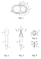
- la figure 1 est une vue en coupe schématique d'une boíte de vitesses équipée d'un reniflard selon l'invention,
- la figure 2 est une vue en élévation du tuyau formant le reniflard,
- la figure 3 est une vue en coupe partielle montrant l'extrémité aplatie du tuyau, après rotation de celui-ci de 90° par rapport à sa position sur la figure 2,
- la figure 4 est une vue en coupe suivant le plan A - A de la figure 3, montrant l'extrémité du tuyau en position active de fonctionnement,
- la figure 5 est une vue analogue à la figure 4, l'extrémité du tuyau étant en position de repos.
- FIG. 1 is a diagrammatic sectional view of a gearbox equipped with a breather according to the invention,
- FIG. 2 is an elevational view of the pipe forming the breather,
- FIG. 3 is a partial sectional view showing the flattened end of the pipe, after rotation thereof by 90 ° with respect to its position in FIG. 2,
- FIG. 4 is a sectional view along the plane A - A of FIG. 3, showing the end of the pipe in the active operating position,
- Figure 5 is a view similar to Figure 4, the end of the pipe being in the rest position.
La figure 1 montre une boíte de vitesses 1 comportant un reniflard
constitué par un tuyau 2 raccordé à une ouverture 3 prévue sur le dessus de
la boíte de vitesses, qui communique avec l'intérieur de celle-ci.FIG. 1 shows a gearbox 1 comprising a breather
constituted by a
Conformément à l'invention, le tuyau 2 est en matière déformable et
élastique et comporte à son extrémité opposée à celle raccordée à
l'ouverture 3, une zone aplatie 4 (voir figures 2 à 5) se terminant par deux
parois 5, 6 en contact pouvant s'écarter élastiquement l'une de l'autre
comme montré sur la figure 4, sous l'effet de la pression des gaz engendrés
dans la boíte de vitesses 1 lors de son fonctionnement et se rapprocher l'une
de l'autre (voir figure 5) après l'arrêt du fonctionnement de la boíte de
vitesses, et diminution de la pression des gaz.According to the invention, the
Dans la position dans laquelle les deux parois 5, 6 sont rapprochées
l'une de l'autre, elles définissent entre elles, un passage perméable à l'air,
mais imperméable au passage d'impuretés ou d'eau. In the position in which the two
Ce passage est constitué (voir figure 5) par une ou plusieurs gorges
5a, 6a formées sur la face interne de chacune des deux parois 5, 6 en
contact. Chaque gorge 5a, 6a forme avec la gorge adjacente de l'autre paroi
une ouverture circulaire de faible diamètre par exemple compris entre 0,01 et
0,2 mm. Ces petites ouvertures sont suffisantes pour permettre à la boíte de
vitesses de « respirer » tout en évitant la pénétration d'impuretés ou d'eau.This passage is constituted (see Figure 5) by one or
Le tuyau 2 est de préférence en élastomère préformé pour former la
zone aplatie 4. Cet élastomère doit bien entendu résister en continu aux
vapeurs d'huile et à une température supérieure à 100°C.The
De préférence, la zone aplatie 4 s'étend sur une distance comprise
entre 1/10ème et 1/3 de la longueur du tuyau 2 pour obtenir un bon contact
entre les parois 5 et 6.Preferably, the flattened zone 4 extends over a distance of between 1/10 th and 1/3 of the length of the
Par ailleurs, dans l'exemple représenté (figures 2 et 3) le tuyau 2
comporte à son extrémité opposée à la zone aplatie 4, un embout 7 de
section plus faible que celle du tuyau, destiné à être emboíté dans l'ouverture
3 de la boíte de vitesses 1.Moreover, in the example shown (FIGS. 2 and 3) the
Le reniflard que l'on vient de décrire fonctionne de la façon suivante :
Dans cette position subsistent deux petites ouvertures formées par les
gorges 5a, 6a qui permettent à l'air de pénétrer à l'intérieur de la boíte de
vitesses 1 afin que celle-ci puisse « respirer ».In this position there are two small openings formed by
Cependant, ces petites ouvertures empêchent la pénétration des impuretés telles que des grains de sable ou de l'eau qui sont susceptibles d'endommager les mécanismes situés dans la boíte de vitesses.However, these small openings prevent the penetration of impurities such as grains of sand or water that are susceptible to damage the mechanisms located in the gearbox.
Le principal avantage du reniflard selon l'invention réside dans la simplicité de sa construction et par conséquent de son faible coût.The main advantage of the breather according to the invention lies in the simplicity of its construction and therefore its low cost.
Claims (9)
Applications Claiming Priority (2)
| Application Number | Priority Date | Filing Date | Title |
|---|---|---|---|
| FR0315302A FR2864192B1 (en) | 2003-12-23 | 2003-12-23 | SPEED BOX BREAKER |
| FR0315302 | 2003-12-23 |
Publications (2)
| Publication Number | Publication Date |
|---|---|
| EP1548331A1 true EP1548331A1 (en) | 2005-06-29 |
| EP1548331B1 EP1548331B1 (en) | 2007-11-28 |
Family
ID=34531343
Family Applications (1)
| Application Number | Title | Priority Date | Filing Date |
|---|---|---|---|
| EP20040300896 Not-in-force EP1548331B1 (en) | 2003-12-23 | 2004-12-15 | Breather structure for gearbox |
Country Status (3)
| Country | Link |
|---|---|
| EP (1) | EP1548331B1 (en) |
| DE (1) | DE602004010355T2 (en) |
| FR (1) | FR2864192B1 (en) |
Cited By (1)
| Publication number | Priority date | Publication date | Assignee | Title |
|---|---|---|---|---|
| WO2014195601A1 (en) * | 2013-06-05 | 2014-12-11 | Peugeot Citroen Automobiles Sa | Device for venting a motor vehicle gearbox |
Citations (3)
| Publication number | Priority date | Publication date | Assignee | Title |
|---|---|---|---|---|
| US3686973A (en) * | 1969-10-20 | 1972-08-29 | Gen Motors Corp | Method and apparatus for control of transmission breathing |
| FR2438774A1 (en) * | 1978-10-12 | 1980-05-09 | Renault | VACUUM CAPSULE FOR AUTOMATIC TRANSMISSION |
| DE3810344A1 (en) * | 1987-04-04 | 1989-07-13 | Zahnradfabrik Friedrichshafen | Breather device for a gear case |
-
2003
- 2003-12-23 FR FR0315302A patent/FR2864192B1/en not_active Expired - Fee Related
-
2004
- 2004-12-15 EP EP20040300896 patent/EP1548331B1/en not_active Not-in-force
- 2004-12-15 DE DE200460010355 patent/DE602004010355T2/en active Active
Patent Citations (3)
| Publication number | Priority date | Publication date | Assignee | Title |
|---|---|---|---|---|
| US3686973A (en) * | 1969-10-20 | 1972-08-29 | Gen Motors Corp | Method and apparatus for control of transmission breathing |
| FR2438774A1 (en) * | 1978-10-12 | 1980-05-09 | Renault | VACUUM CAPSULE FOR AUTOMATIC TRANSMISSION |
| DE3810344A1 (en) * | 1987-04-04 | 1989-07-13 | Zahnradfabrik Friedrichshafen | Breather device for a gear case |
Cited By (3)
| Publication number | Priority date | Publication date | Assignee | Title |
|---|---|---|---|---|
| WO2014195601A1 (en) * | 2013-06-05 | 2014-12-11 | Peugeot Citroen Automobiles Sa | Device for venting a motor vehicle gearbox |
| FR3006737A1 (en) * | 2013-06-05 | 2014-12-12 | Peugeot Citroen Automobiles Sa | DEVICE FOR THE OPENING OF A MOTOR VEHICLE GEARBOX |
| CN105308363A (en) * | 2013-06-05 | 2016-02-03 | 标致·雪铁龙汽车公司 | Device for venting a motor vehicle gearbox |
Also Published As
| Publication number | Publication date |
|---|---|
| FR2864192A1 (en) | 2005-06-24 |
| FR2864192B1 (en) | 2006-03-03 |
| DE602004010355T2 (en) | 2008-11-13 |
| EP1548331B1 (en) | 2007-11-28 |
| DE602004010355D1 (en) | 2008-01-10 |
Similar Documents
| Publication | Publication Date | Title |
|---|---|---|
| EP2934267B1 (en) | Suction trapdoor of vacuum cleaner | |
| EP0860112B1 (en) | Watertight fishing reel | |
| FR2582764A1 (en) | PNEUMATIC SPRING | |
| CH437935A (en) | Clutch device | |
| EP1342458B1 (en) | Gastric constriction device having a balloon with bellow pleats | |
| CH631248A5 (en) | DEVICE FOR BREAKING THE ICE AND DETERMINING THE SLUDGE OF A SCREW AND BALL NUT ASSEMBLY. | |
| EP1548331B1 (en) | Breather structure for gearbox | |
| FR2751392A1 (en) | Tensioning pulley with fastening bolt and covering cap | |
| EP0567374A1 (en) | Dispensing cap for liquid or pastry products | |
| EP3655280B1 (en) | Venting device with a membrane for a liquid tank of a vehicle | |
| FR2740402A1 (en) | MOTOR VEHICLE FUEL TANK PROVIDED WITH AN IMPROVED FREE AIR BREAKING DEVICE AND IMPROVED FREE AIR BREAKING DEVICE | |
| FR2521934A1 (en) | VALVE ARRANGEMENT FOR COMPENSATION TANK FOR HYDRAULIC BRAKE SYSTEM | |
| EP1831591B1 (en) | Oil guiding device for gearbox hollow shaft | |
| EP2206177B1 (en) | Device for degassing the battery of an automobile | |
| FR2977598A1 (en) | ANTI-ODOR SLEEVE FOR EXTREMITY OF LIQUID EXHAUST PIPE AND ASSOCIATED INSTALLATION | |
| EP1378385A1 (en) | Tip for a roll-up device for winding material such as tarpaulins, specially for vehicles | |
| FR2970055A1 (en) | Sealing device e.g. bidirectional mechanical sealing device, for e.g. sampling valve in liquid pipe, has joints to control deformation of monoblock assembly formed by joints and seat when piston is supported on seat in unbalanced manner | |
| EP3793894B1 (en) | Fresh-air supply system for a submarine and submarine including such a system | |
| FR3047474A1 (en) | SHUTTER DEVICE | |
| FR2786836A1 (en) | Hydraulically operated clutch thrust bearing substantially made from plastic | |
| CA2401307A1 (en) | Flap accessory | |
| FR3130316A1 (en) | Exhaust duct comprising means for holding a screen | |
| CH670683A5 (en) | ||
| FR2760577A1 (en) | Geared motor assembly for vehicle windscreen wipers | |
| FR2877781A1 (en) | Electrical rotating machine e.g. engine starter, for motor vehicle, has groove formed in outer circumference of protrusion of yoke to direct water penetrating into upper part of gap between pulley and yoke towards lowest part of yoke |
Legal Events
| Date | Code | Title | Description |
|---|---|---|---|
| PUAI | Public reference made under article 153(3) epc to a published international application that has entered the european phase |
Free format text: ORIGINAL CODE: 0009012 |
|
| AK | Designated contracting states |
Kind code of ref document: A1 Designated state(s): AT BE BG CH CY CZ DE DK EE ES FI FR GB GR HU IE IS IT LI LT LU MC NL PL PT RO SE SI SK TR |
|
| AX | Request for extension of the european patent |
Extension state: AL BA HR LV MK YU |
|
| 17P | Request for examination filed |
Effective date: 20051212 |
|
| AKX | Designation fees paid |
Designated state(s): AT BE BG CH CY CZ DE DK EE ES FI FR GB GR HU IE IS IT LI LT LU MC NL PL PT RO SE SI SK TR |
|
| GRAP | Despatch of communication of intention to grant a patent |
Free format text: ORIGINAL CODE: EPIDOSNIGR1 |
|
| GRAS | Grant fee paid |
Free format text: ORIGINAL CODE: EPIDOSNIGR3 |
|
| GRAA | (expected) grant |
Free format text: ORIGINAL CODE: 0009210 |
|
| AK | Designated contracting states |
Kind code of ref document: B1 Designated state(s): AT BE BG CH CY CZ DE DK EE ES FI FR GB GR HU IE IS IT LI LT LU MC NL PL PT RO SE SI SK TR |
|
| REG | Reference to a national code |
Ref country code: GB Ref legal event code: FG4D Free format text: NOT ENGLISH |
|
| REG | Reference to a national code |
Ref country code: IE Ref legal event code: FG4D Free format text: LANGUAGE OF EP DOCUMENT: FRENCH |
|
| REG | Reference to a national code |
Ref country code: CH Ref legal event code: EP |
|
| REF | Corresponds to: |
Ref document number: 602004010355 Country of ref document: DE Date of ref document: 20080110 Kind code of ref document: P |
|
| PG25 | Lapsed in a contracting state [announced via postgrant information from national office to epo] |
Ref country code: ES Free format text: LAPSE BECAUSE OF FAILURE TO SUBMIT A TRANSLATION OF THE DESCRIPTION OR TO PAY THE FEE WITHIN THE PRESCRIBED TIME-LIMIT Effective date: 20080311 Ref country code: NL Free format text: LAPSE BECAUSE OF FAILURE TO SUBMIT A TRANSLATION OF THE DESCRIPTION OR TO PAY THE FEE WITHIN THE PRESCRIBED TIME-LIMIT Effective date: 20071128 Ref country code: SE Free format text: LAPSE BECAUSE OF FAILURE TO SUBMIT A TRANSLATION OF THE DESCRIPTION OR TO PAY THE FEE WITHIN THE PRESCRIBED TIME-LIMIT Effective date: 20080228 |
|
| NLV1 | Nl: lapsed or annulled due to failure to fulfill the requirements of art. 29p and 29m of the patents act | ||
| PG25 | Lapsed in a contracting state [announced via postgrant information from national office to epo] |
Ref country code: FI Free format text: LAPSE BECAUSE OF FAILURE TO SUBMIT A TRANSLATION OF THE DESCRIPTION OR TO PAY THE FEE WITHIN THE PRESCRIBED TIME-LIMIT Effective date: 20071128 Ref country code: IS Free format text: LAPSE BECAUSE OF FAILURE TO SUBMIT A TRANSLATION OF THE DESCRIPTION OR TO PAY THE FEE WITHIN THE PRESCRIBED TIME-LIMIT Effective date: 20080328 Ref country code: LT Free format text: LAPSE BECAUSE OF FAILURE TO SUBMIT A TRANSLATION OF THE DESCRIPTION OR TO PAY THE FEE WITHIN THE PRESCRIBED TIME-LIMIT Effective date: 20071128 Ref country code: PL Free format text: LAPSE BECAUSE OF FAILURE TO SUBMIT A TRANSLATION OF THE DESCRIPTION OR TO PAY THE FEE WITHIN THE PRESCRIBED TIME-LIMIT Effective date: 20071128 Ref country code: SI Free format text: LAPSE BECAUSE OF FAILURE TO SUBMIT A TRANSLATION OF THE DESCRIPTION OR TO PAY THE FEE WITHIN THE PRESCRIBED TIME-LIMIT Effective date: 20071128 Ref country code: BG Free format text: LAPSE BECAUSE OF FAILURE TO SUBMIT A TRANSLATION OF THE DESCRIPTION OR TO PAY THE FEE WITHIN THE PRESCRIBED TIME-LIMIT Effective date: 20080228 |
|
| GBV | Gb: ep patent (uk) treated as always having been void in accordance with gb section 77(7)/1977 [no translation filed] | ||
| BERE | Be: lapsed |
Owner name: RENAULT Effective date: 20071231 |
|
| PG25 | Lapsed in a contracting state [announced via postgrant information from national office to epo] |
Ref country code: AT Free format text: LAPSE BECAUSE OF FAILURE TO SUBMIT A TRANSLATION OF THE DESCRIPTION OR TO PAY THE FEE WITHIN THE PRESCRIBED TIME-LIMIT Effective date: 20071128 |
|
| PG25 | Lapsed in a contracting state [announced via postgrant information from national office to epo] |
Ref country code: MC Free format text: LAPSE BECAUSE OF NON-PAYMENT OF DUE FEES Effective date: 20071231 Ref country code: DK Free format text: LAPSE BECAUSE OF FAILURE TO SUBMIT A TRANSLATION OF THE DESCRIPTION OR TO PAY THE FEE WITHIN THE PRESCRIBED TIME-LIMIT Effective date: 20071128 Ref country code: CZ Free format text: LAPSE BECAUSE OF FAILURE TO SUBMIT A TRANSLATION OF THE DESCRIPTION OR TO PAY THE FEE WITHIN THE PRESCRIBED TIME-LIMIT Effective date: 20071128 |
|
| PG25 | Lapsed in a contracting state [announced via postgrant information from national office to epo] |
Ref country code: RO Free format text: LAPSE BECAUSE OF FAILURE TO SUBMIT A TRANSLATION OF THE DESCRIPTION OR TO PAY THE FEE WITHIN THE PRESCRIBED TIME-LIMIT Effective date: 20071128 Ref country code: SK Free format text: LAPSE BECAUSE OF FAILURE TO SUBMIT A TRANSLATION OF THE DESCRIPTION OR TO PAY THE FEE WITHIN THE PRESCRIBED TIME-LIMIT Effective date: 20071128 |
|
| PG25 | Lapsed in a contracting state [announced via postgrant information from national office to epo] |
Ref country code: PT Free format text: LAPSE BECAUSE OF FAILURE TO SUBMIT A TRANSLATION OF THE DESCRIPTION OR TO PAY THE FEE WITHIN THE PRESCRIBED TIME-LIMIT Effective date: 20080428 Ref country code: BE Free format text: LAPSE BECAUSE OF NON-PAYMENT OF DUE FEES Effective date: 20071231 |
|
| PLBE | No opposition filed within time limit |
Free format text: ORIGINAL CODE: 0009261 |
|
| STAA | Information on the status of an ep patent application or granted ep patent |
Free format text: STATUS: NO OPPOSITION FILED WITHIN TIME LIMIT |
|
| PG25 | Lapsed in a contracting state [announced via postgrant information from national office to epo] |
Ref country code: IE Free format text: LAPSE BECAUSE OF NON-PAYMENT OF DUE FEES Effective date: 20071217 |
|
| 26N | No opposition filed |
Effective date: 20080829 |
|
| PG25 | Lapsed in a contracting state [announced via postgrant information from national office to epo] |
Ref country code: GB Free format text: LAPSE BECAUSE OF FAILURE TO SUBMIT A TRANSLATION OF THE DESCRIPTION OR TO PAY THE FEE WITHIN THE PRESCRIBED TIME-LIMIT Effective date: 20071128 |
|
| REG | Reference to a national code |
Ref country code: FR Ref legal event code: ST Effective date: 20081031 |
|
| PG25 | Lapsed in a contracting state [announced via postgrant information from national office to epo] |
Ref country code: GR Free format text: LAPSE BECAUSE OF FAILURE TO SUBMIT A TRANSLATION OF THE DESCRIPTION OR TO PAY THE FEE WITHIN THE PRESCRIBED TIME-LIMIT Effective date: 20080229 Ref country code: EE Free format text: LAPSE BECAUSE OF FAILURE TO SUBMIT A TRANSLATION OF THE DESCRIPTION OR TO PAY THE FEE WITHIN THE PRESCRIBED TIME-LIMIT Effective date: 20071128 |
|
| PG25 | Lapsed in a contracting state [announced via postgrant information from national office to epo] |
Ref country code: FR Free format text: LAPSE BECAUSE OF NON-PAYMENT OF DUE FEES Effective date: 20071231 |
|
| PG25 | Lapsed in a contracting state [announced via postgrant information from national office to epo] |
Ref country code: CY Free format text: LAPSE BECAUSE OF FAILURE TO SUBMIT A TRANSLATION OF THE DESCRIPTION OR TO PAY THE FEE WITHIN THE PRESCRIBED TIME-LIMIT Effective date: 20071128 |
|
| REG | Reference to a national code |
Ref country code: CH Ref legal event code: PL |
|
| PG25 | Lapsed in a contracting state [announced via postgrant information from national office to epo] |
Ref country code: LU Free format text: LAPSE BECAUSE OF NON-PAYMENT OF DUE FEES Effective date: 20071215 |
|
| PG25 | Lapsed in a contracting state [announced via postgrant information from national office to epo] |
Ref country code: HU Free format text: LAPSE BECAUSE OF FAILURE TO SUBMIT A TRANSLATION OF THE DESCRIPTION OR TO PAY THE FEE WITHIN THE PRESCRIBED TIME-LIMIT Effective date: 20080529 Ref country code: TR Free format text: LAPSE BECAUSE OF FAILURE TO SUBMIT A TRANSLATION OF THE DESCRIPTION OR TO PAY THE FEE WITHIN THE PRESCRIBED TIME-LIMIT Effective date: 20071128 |
|
| PG25 | Lapsed in a contracting state [announced via postgrant information from national office to epo] |
Ref country code: CH Free format text: LAPSE BECAUSE OF NON-PAYMENT OF DUE FEES Effective date: 20081231 Ref country code: LI Free format text: LAPSE BECAUSE OF NON-PAYMENT OF DUE FEES Effective date: 20081231 |
|
| PG25 | Lapsed in a contracting state [announced via postgrant information from national office to epo] |
Ref country code: IT Free format text: LAPSE BECAUSE OF NON-PAYMENT OF DUE FEES Effective date: 20071231 |
|
| PGFP | Annual fee paid to national office [announced via postgrant information from national office to epo] |
Ref country code: DE Payment date: 20141211 Year of fee payment: 11 |
|
| REG | Reference to a national code |
Ref country code: DE Ref legal event code: R119 Ref document number: 602004010355 Country of ref document: DE |
|
| PG25 | Lapsed in a contracting state [announced via postgrant information from national office to epo] |
Ref country code: DE Free format text: LAPSE BECAUSE OF NON-PAYMENT OF DUE FEES Effective date: 20160701 |