EP1548328A1 - Système différentiel à appui conique - Google Patents
Système différentiel à appui conique Download PDFInfo
- Publication number
- EP1548328A1 EP1548328A1 EP04300895A EP04300895A EP1548328A1 EP 1548328 A1 EP1548328 A1 EP 1548328A1 EP 04300895 A EP04300895 A EP 04300895A EP 04300895 A EP04300895 A EP 04300895A EP 1548328 A1 EP1548328 A1 EP 1548328A1
- Authority
- EP
- European Patent Office
- Prior art keywords
- transmission member
- housing
- differential system
- sun gear
- shoulder
- Prior art date
- Legal status (The legal status is an assumption and is not a legal conclusion. Google has not performed a legal analysis and makes no representation as to the accuracy of the status listed.)
- Granted
Links
- 230000005540 biological transmission Effects 0.000 claims abstract description 62
- 210000000056 organ Anatomy 0.000 description 10
- 230000035939 shock Effects 0.000 description 4
- 230000005284 excitation Effects 0.000 description 3
- 230000006835 compression Effects 0.000 description 2
- 238000007906 compression Methods 0.000 description 2
- 230000002238 attenuated effect Effects 0.000 description 1
- 230000008878 coupling Effects 0.000 description 1
- 238000010168 coupling process Methods 0.000 description 1
- 238000005859 coupling reaction Methods 0.000 description 1
- 230000005226 mechanical processes and functions Effects 0.000 description 1
Images
Classifications
-
- F—MECHANICAL ENGINEERING; LIGHTING; HEATING; WEAPONS; BLASTING
- F16—ENGINEERING ELEMENTS AND UNITS; GENERAL MEASURES FOR PRODUCING AND MAINTAINING EFFECTIVE FUNCTIONING OF MACHINES OR INSTALLATIONS; THERMAL INSULATION IN GENERAL
- F16H—GEARING
- F16H48/00—Differential gearings
- F16H48/06—Differential gearings with gears having orbital motion
- F16H48/08—Differential gearings with gears having orbital motion comprising bevel gears
-
- F—MECHANICAL ENGINEERING; LIGHTING; HEATING; WEAPONS; BLASTING
- F16—ENGINEERING ELEMENTS AND UNITS; GENERAL MEASURES FOR PRODUCING AND MAINTAINING EFFECTIVE FUNCTIONING OF MACHINES OR INSTALLATIONS; THERMAL INSULATION IN GENERAL
- F16H—GEARING
- F16H48/00—Differential gearings
- F16H48/06—Differential gearings with gears having orbital motion
- F16H48/08—Differential gearings with gears having orbital motion comprising bevel gears
- F16H2048/082—Differential gearings with gears having orbital motion comprising bevel gears characterised by the arrangement of output shafts
-
- F—MECHANICAL ENGINEERING; LIGHTING; HEATING; WEAPONS; BLASTING
- F16—ENGINEERING ELEMENTS AND UNITS; GENERAL MEASURES FOR PRODUCING AND MAINTAINING EFFECTIVE FUNCTIONING OF MACHINES OR INSTALLATIONS; THERMAL INSULATION IN GENERAL
- F16H—GEARING
- F16H57/00—General details of gearing
- F16H57/02—Gearboxes; Mounting gearing therein
- F16H57/021—Shaft support structures, e.g. partition walls, bearing eyes, casing walls or covers with bearings
- F16H57/022—Adjustment of gear shafts or bearings
- F16H2057/0221—Axial adjustment
Definitions
- the present invention relates to a differential system for motor vehicles to improve the mode of transmission between an output shaft and wheel members.
- Known different systems comprise a housing in which are housed two opposite planetary pairs coupled by two opposed satellites mounted crazy on the housing.
- Two opposite coaxial bores are housed in the housing and they allow to house two organs of transmission at one of the ends of which are mounted the sun gear, the other ends extending outside said housing.
- the organs of transmission are rotatably mounted in the bores and they are intended to be coupled in rotation to the wheel members.
- the housing is rotatably coupled thereto via a crown to a gearbox output pinion, for example,
- a disadvantage of these differential systems lies in the flapping of the transmission members in the bores. These beats are generated by a pestle excitation of the motor, which generates the excitation of a specific mode of transmission modulated by the frequency of the wheel revolution and shocks during the deformation of this transmission.
- a problem that arises and that aims to solve this invention is then to provide a differential system that avoids the beats of the transmission member without reducing the differential performance.
- the present invention proposes a differential system for motor vehicle, comprising a housing in which are drilled two opposite coaxial bores. each bore having an outer edge flared substantially conical, said housing containing two planetary each connected to a transmission member which extends longitudinally along an axis of symmetry outside said housing through the bore corresponding and which is provided with annular means conical range adapted to cooperate with said flared outer edge; said organ of transmission having a tapered shoulder forming said annular means and said transmission member being driven elastically along said axis towards said housing so as to maintain said shoulder bearing sliding against said flared outer edge.
- a feature of the invention lies in the mode of axial connection of the transmission member and the housing; said organ of The transmission has a longer reach thanks to the tapered reach, it is therefore better guided and in addition, the organ of transmission is driven elastically against the housing, but permitting their relative sliding in rotation, which limits the excitation of the transmission and therefore the beats.
- each transmission member is rotatably connected with a transmission shaft which is kept at a distance from said housing and said transmission member is driven elastically by a first spring which is supported on said drive shaft.
- the first spring which has a relatively large amplitude of compression and a determined stiffness, one precisely determines the intensity of the force support of the conical bearing shoulder against the flared outer edge, which support must nevertheless allow friction.
- each transmission member is linked in translation with the sun gear corresponding by a second spring adapted to cause said body transmission to said sun gear.
- the transmission member is prestressed against the differential case thanks to the planetary constitutes a point of support for elastically driving the organ of transmission to him.
- said body transmission comprises a sleeve having a shoulder internal orientation in a direction opposite to said sun gear and a screw which has a head and a screwable end, said screw being adapted to be engaged in said sleeve, said head compressing said second spring against said inner shoulder while the screw end is secured said sun gear.
- the outer shapes of the sleeve fill all the mechanical functions of the transmission member and said sleeve is resiliently connected to the sun gear by means fully housed inside, which does not interfere with the operation of all,
- said housing presents a internal bearing surface symmetrical with respect to said bore and adapted to receive said sun gear in support, in this way, a wall of the housing, around of the bore, is adapted to be sandwiched between the sun gear of conical bearing shoulder, the sun gear being adapted to support and slide against said internal bearing surface while the shoulder itself, supports and slides against the flared edge.
- the planet and the organ are linked in rotation, they are driven simultaneously in rotation relative to the housing.
- said sun gear comprises a spherical sector adapted to cooperate with said support surface which is of spherical symmetry. So, not only does the planetary have a large support surface but also, it is perfectly guided in rotation by this bearing surface of spherical symmetry when it is driven by rotation relative to the housing.
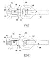
- Figure 1 schematically illustrates a part of a system differential according to the invention, which comprises here a housing part differential 110 in which is arranged along an axis of symmetry A, a bore 112 and which isolates the interior 114 of the housing 110 from outside 116.
- the bore 112 has an outer edge 118 flared, conical symmetry.
- a transmission member 120 is extended partially for the purposes of this description, and it presents a first end 122 opening inside 114 of the housing 110, said first end 122 being intended to be mounted in a planetary gear, which will be described below in detail in a second embodiment variant, the transmission member 120 furthermore has a second end 124 which is rotatably connected through a joint articulated 126 to a transmission shaft 128, which is coupled to wheel components.
- the second end 124 has a shoulder 130 within range conical adapted to cooperate and bear against the outer edge 118 flared. Furthermore, the transmission shaft 128 and the transmission 120 are movable in translation relative to each other and they are held apart from each other by a coil spring 132 tablet interposed between the two.
- the spring 132 has a sufficiently low stiffness and the contact between the shoulder 130 and the outer edge 118 is sufficiently lubricated on the one hand, the sliding of one against the other can be carried out with a low friction force, and this so as not to decrease the performance of the differential system, and secondly, for the transfer vibratory element coupling is limited.
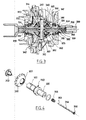
- FIG 3 there is shown a differential system substantially full.
- a housing 310 whose interior 314 is a space of substantially spherical symmetry and which contains two planetary facing 323, spaced from each other and two satellites 340 mounted crazy and opposed to each other on a central axis 342 concurrent. extended between the planetaries 323, each of the satellites 340 being coupled in rotation with the two planetaries 323.
- the differential system comprises two transmission 320 which respectively pass through a bore 312, both bores 312 being coaxial.
- Transmission components present a first end 322 which is connected to the sun gear 323 which corresponds, according to means which will be described below with reference to the Figure 4.
- the planetaries 323 comprise a part spherical sector 350 whose surface is adapted to come into contact to marry the shape, an inner wall portion 352 of the interior 314 located around the bore 312. This portion of the wall internal 352 constituting the concave face of a spherical segment.
- the transmission members 320 have a second end 324 which has a shoulder 330 of conical bearing against a outer edge 318 flared around the bore 312.
- the second end 324 is rotatably coupled to a transmission shaft 328 which itself is coupled to the wheel members not shown.
- Figure 4 illustrates the mode of connection between the planetary gear 323 and the transmission members 320 which allows them to drive towards one another in such a way that the shoulder 330 with a conical bearing can be driven to force against the flared outer edge 318 while the surface of the part in spherical sector 350 of the planet 323 is, she, driven against the inner wall portion 352.
- the transmission member 320 consists of a sleeve adapted to receive inside a longitudinal screw 354 completed by a screwable part 355.
- the screw 354 has at the other end a head 356 intended to bear on the end of a helical spring 358 which, housed in the sleeve 320, can be supported against a shoulder 359 which will be described hereinafter with reference to FIG. heard, the coil spring 358 could be replaced by other types of spring, for example by conical spring washer type " Beautiful city ".
- the screw 354 threaded into the spring 358 and engaged in the sleeve 320 is adapted to be screwed into a nut 360 which him, comes apply against a side of the sun gear 323 opposite the surface of the spherical sector 350.
- first end 322 presents first grooves adapted to cooperate with second internal splines to the sun gear 323 so as to bind in rotation the transmission member 320 and the planetary 323.
- the screw 354 maintains compression the spring 358 against the internal shoulder 359, the organ transmission being locked in translation, the shoulder 330 against the edge external 18 flared, while the screw portion 355, on the opposite, maintains the nut 360 and consequently the sun gear 323 against the inner wall 352.
- the sun gear 323 and the shoulder 330 compress in sandwich the wall of the housing 310 around the bore 312.
- the tapered shoulder 330 is maintained in support against the outer edge 18 flared housing by means internal to the case.
- the screw 354 makes it possible to precisely adjust the bearing force of the shoulder 330 against the outer edge 318, of such so that in normal operation they can be rotated at different speeds without excessive friction.
- the intensity of the shocks between the transmission and the housing 310 is attenuated and therefore the beats of the transmission member 320 too. In this way, no only the handling of the vehicle is improved but the noise generated by these beats are considerably reduced, which improves driving comfort as well.
Landscapes
- Engineering & Computer Science (AREA)
- General Engineering & Computer Science (AREA)
- Mechanical Engineering (AREA)
- Retarders (AREA)
- General Details Of Gearings (AREA)
- Load-Engaging Elements For Cranes (AREA)
Abstract
Description
- la Figure 1 est une vue schématique partielle en coupe axiale d'un système différentiel conforme à l'invention selon une première variante d'exécution et dans une première position ;
- la Figure 2 est une vue schématique identique à la Figure 1, où le système différentiel est dans une seconde position ;
- la Figure 3 est une vue schématique en coupe axiale d'un système différentiel conforme à l'invention selon une seconde variante de réalisation ; et,
- la Figure 4 est une vue schématique de détail éclatée et en perspective, d'un élément du système illustré sur la Figure 3.
Claims (7)
- Système différentiel pour véhicule automobile, comportant un boítier dans lequel sont percés deux alésages opposés coaxiaux, chaque alésage présentant un bord externe évasé sensiblement conique, ledit boítier contenant deux planétaires chacun relié à un organe de transmission qui s'étend longitudinalement selon un axe de symétrie en dehors dudit boítier à travers l'alésage correspondant et qui est muni de moyens annulaires à portée conique adaptés à coopérer avec ledit bord externe évasé ;
caractérisé en ce que ledit organe de transmission (120, 320) présente un épaulement (130, 330) à portée conique formant lesdits moyens annulaires et en ce que ledit organe de transmission (120, 320) est entraíné élastiquement selon ledit axe vers ledit boítier (110, 310) de façon à maintenir ledit épaulement (130, 330) en appui glissant contre ledit bord externe (118, 318) évasé. - Système différentiel selon la revendication 1, caractérisé en ce que chaque organe de transmission (120) est lié en rotation avec un arbre de transmission (128) qui est maintenu à distance dudit boítier (110) et en ce que ledit organe de transmission (120) est entraíné élastiquement par un premier ressort (132) qui prend appui sur ledit arbre de transmission (128).
- Système différentiel selon la revendication 2, caractérisé en ce que ledit arbre de transmission (128) et ledit organe de transmission (120) sont reliés ensemble par un joint articulé (126).
- Système différentiel selon la revendication 1, caractérisé en ce que chaque organe de transmission (320) est lié en translation avec le planétaire (323) correspondant par un second ressort (358) adaptés à entraíner ledit organe de transmission (320) vers ledit planétaire (323).
- Système différentiel selon la revendication 4, caractérisé en ce que ledit organe de transmission (320) comporte un manchon qui présente un épaulement interne (359) orienté dans un sens opposé audit planétaire (323) et une vis (354) qui présente une tête (356) et une extrémité vissable (355), ladite vis (354) étant adaptée à être engagée dans ledit manchon, ladite tête (356) comprimant ledit second ressort (358) contre ledit épaulement interne (359) tandis que l'extrémité, vissable (355) est solidaire dudit planétaire (323).
- Système différentiel selon la revendication 4 ou 5, caractérisé en ce que ledit boítier (310) présente une surface d'appui interne (352) symétrique par rapport audit alésage (312) et adapté à recevoir ledit planétaire (323) en appui.
- Système différentiel selon la revendication 6, caractérisé en ce que ledit planétaire (323) comporte un secteur sphérique (350) adapté à coopérer avec ladite surface d'appui (352) qui est de symétrie sphérique.
Applications Claiming Priority (2)
| Application Number | Priority Date | Filing Date | Title |
|---|---|---|---|
| FR0315311 | 2003-12-23 | ||
| FR0315311A FR2864187B1 (fr) | 2003-12-23 | 2003-12-23 | Systeme differentiel a appui conique. |
Publications (2)
| Publication Number | Publication Date |
|---|---|
| EP1548328A1 true EP1548328A1 (fr) | 2005-06-29 |
| EP1548328B1 EP1548328B1 (fr) | 2008-02-06 |
Family
ID=34531345
Family Applications (1)
| Application Number | Title | Priority Date | Filing Date |
|---|---|---|---|
| EP04300895A Expired - Lifetime EP1548328B1 (fr) | 2003-12-23 | 2004-12-15 | Système différentiel à appui conique |
Country Status (4)
| Country | Link |
|---|---|
| EP (1) | EP1548328B1 (fr) |
| AT (1) | ATE385554T1 (fr) |
| DE (1) | DE602004011649T2 (fr) |
| FR (1) | FR2864187B1 (fr) |
Citations (3)
| Publication number | Priority date | Publication date | Assignee | Title |
|---|---|---|---|---|
| DE2555644A1 (de) * | 1975-12-11 | 1977-06-16 | Volkswagenwerk Ag | Anordnung mit einer gelagerten gestreckten welle |
| US4815337A (en) | 1987-10-19 | 1989-03-28 | Peloquin Gary T | Locking ring for independent rear suspensions |
| DE10303862A1 (de) * | 2002-01-31 | 2003-08-14 | Visteon Global Tech Inc | Aufbau eines Differentials |
-
2003
- 2003-12-23 FR FR0315311A patent/FR2864187B1/fr not_active Expired - Fee Related
-
2004
- 2004-12-15 DE DE602004011649T patent/DE602004011649T2/de not_active Expired - Lifetime
- 2004-12-15 EP EP04300895A patent/EP1548328B1/fr not_active Expired - Lifetime
- 2004-12-15 AT AT04300895T patent/ATE385554T1/de not_active IP Right Cessation
Patent Citations (3)
| Publication number | Priority date | Publication date | Assignee | Title |
|---|---|---|---|---|
| DE2555644A1 (de) * | 1975-12-11 | 1977-06-16 | Volkswagenwerk Ag | Anordnung mit einer gelagerten gestreckten welle |
| US4815337A (en) | 1987-10-19 | 1989-03-28 | Peloquin Gary T | Locking ring for independent rear suspensions |
| DE10303862A1 (de) * | 2002-01-31 | 2003-08-14 | Visteon Global Tech Inc | Aufbau eines Differentials |
Also Published As
| Publication number | Publication date |
|---|---|
| ATE385554T1 (de) | 2008-02-15 |
| DE602004011649D1 (de) | 2008-03-20 |
| EP1548328B1 (fr) | 2008-02-06 |
| FR2864187B1 (fr) | 2006-02-17 |
| FR2864187A1 (fr) | 2005-06-24 |
| DE602004011649T2 (de) | 2009-01-29 |
Similar Documents
| Publication | Publication Date | Title |
|---|---|---|
| EP0525663A1 (fr) | Module de roulement moteur, notamment pour véhicule automobile | |
| FR2917682A1 (fr) | Actionneur pour un vehicule automobile, comprenant un carter d'engrenage | |
| FR2979403A1 (fr) | Dispositif de liaison d'une colonne de direction avec un boitier de direction. | |
| EP3175146B1 (fr) | Réducteur de couple | |
| FR3138931A1 (fr) | Actionneur linéaire à joint oscillant | |
| FR2834764A1 (fr) | Ensemble de commande perfectionne pour boite de vitesses robotisee | |
| FR2771784A1 (fr) | Tete de renvoi reglable, notamment pour un accessoire taille-haies | |
| WO2020025343A1 (fr) | Poulie à flasque à écartement variable pour variateur de vitesse | |
| FR2837773A1 (fr) | Appareil de direction du vehicule | |
| EP1548328B1 (fr) | Système différentiel à appui conique | |
| FR2670726A1 (fr) | Phare pour vehicule. | |
| EP0034099A1 (fr) | Colonne de direction pour véhicule automobile | |
| WO2007116073A1 (fr) | Agencement de transmission de mouvement entre notamment un verrou et une serrure de porte de vehicule | |
| FR3001270A3 (fr) | "differentiel de transmission comportant des moyens de friction perfectionnes" | |
| FR2917797A1 (fr) | Transmission entre un organe moteur et des roues et engin comportant une telle transmission | |
| FR2849885A1 (fr) | Perfectionnement aux dispositifs de liaison entre un verrou de porte et une serrure pour vehicule automobile | |
| FR3001271A1 (fr) | "differentiel de transmission, notamment pour vehicule automobile" | |
| WO1994008836A1 (fr) | Direction assistee a haute performance | |
| FR3007484A3 (fr) | "differentiel de transmission comportant des demi-coquilles de friction" | |
| EP2895728B1 (fr) | Vanne de circulation d'un fluide, en particulier gaz d'echappement recircule | |
| FR2529843A1 (fr) | Dispositif de reglage de l'orientation de deux projecteurs d'un vehicule | |
| EP0430748A1 (fr) | Joint de transmission à fixité axiale | |
| FR2654991A1 (fr) | Dispositif de fixation notamment d'un essieu de train arriere de vehicule automobile sur la caisse du vehicule. | |
| EP3523164B1 (fr) | Roue dentée pour un motoréducteur d'essuie-glace | |
| FR3118936A1 (fr) | Système de connexion d’un câble pour un véhicule automobile. |
Legal Events
| Date | Code | Title | Description |
|---|---|---|---|
| PUAI | Public reference made under article 153(3) epc to a published international application that has entered the european phase |
Free format text: ORIGINAL CODE: 0009012 |
|
| AK | Designated contracting states |
Kind code of ref document: A1 Designated state(s): AT BE BG CH CY CZ DE DK EE ES FI FR GB GR HU IE IS IT LI LT LU MC NL PL PT RO SE SI SK TR |
|
| AX | Request for extension of the european patent |
Extension state: AL BA HR LV MK YU |
|
| 17P | Request for examination filed |
Effective date: 20051212 |
|
| AKX | Designation fees paid |
Designated state(s): AT BE BG CH CY CZ DE DK EE ES FI FR GB GR HU IE IS IT LI LT LU MC NL PL PT RO SE SI SK TR |
|
| RIN1 | Information on inventor provided before grant (corrected) |
Inventor name: LEVANT, SEBASTIEN Inventor name: DECOUZ, ANNE-ELISABETH |
|
| GRAP | Despatch of communication of intention to grant a patent |
Free format text: ORIGINAL CODE: EPIDOSNIGR1 |
|
| GRAS | Grant fee paid |
Free format text: ORIGINAL CODE: EPIDOSNIGR3 |
|
| GRAA | (expected) grant |
Free format text: ORIGINAL CODE: 0009210 |
|
| AK | Designated contracting states |
Kind code of ref document: B1 Designated state(s): AT BE BG CH CY CZ DE DK EE ES FI FR GB GR HU IE IS IT LI LT LU MC NL PL PT RO SE SI SK TR |
|
| REG | Reference to a national code |
Ref country code: GB Ref legal event code: FG4D Free format text: NOT ENGLISH |
|
| REG | Reference to a national code |
Ref country code: CH Ref legal event code: EP |
|
| REG | Reference to a national code |
Ref country code: IE Ref legal event code: FG4D Free format text: LANGUAGE OF EP DOCUMENT: FRENCH |
|
| REF | Corresponds to: |
Ref document number: 602004011649 Country of ref document: DE Date of ref document: 20080320 Kind code of ref document: P |
|
| PG25 | Lapsed in a contracting state [announced via postgrant information from national office to epo] |
Ref country code: IS Free format text: LAPSE BECAUSE OF FAILURE TO SUBMIT A TRANSLATION OF THE DESCRIPTION OR TO PAY THE FEE WITHIN THE PRESCRIBED TIME-LIMIT Effective date: 20080606 Ref country code: FI Free format text: LAPSE BECAUSE OF FAILURE TO SUBMIT A TRANSLATION OF THE DESCRIPTION OR TO PAY THE FEE WITHIN THE PRESCRIBED TIME-LIMIT Effective date: 20080206 Ref country code: ES Free format text: LAPSE BECAUSE OF FAILURE TO SUBMIT A TRANSLATION OF THE DESCRIPTION OR TO PAY THE FEE WITHIN THE PRESCRIBED TIME-LIMIT Effective date: 20080517 |
|
| NLV1 | Nl: lapsed or annulled due to failure to fulfill the requirements of art. 29p and 29m of the patents act | ||
| PG25 | Lapsed in a contracting state [announced via postgrant information from national office to epo] |
Ref country code: AT Free format text: LAPSE BECAUSE OF FAILURE TO SUBMIT A TRANSLATION OF THE DESCRIPTION OR TO PAY THE FEE WITHIN THE PRESCRIBED TIME-LIMIT Effective date: 20080206 |
|
| PG25 | Lapsed in a contracting state [announced via postgrant information from national office to epo] |
Ref country code: SI Free format text: LAPSE BECAUSE OF FAILURE TO SUBMIT A TRANSLATION OF THE DESCRIPTION OR TO PAY THE FEE WITHIN THE PRESCRIBED TIME-LIMIT Effective date: 20080206 Ref country code: PL Free format text: LAPSE BECAUSE OF FAILURE TO SUBMIT A TRANSLATION OF THE DESCRIPTION OR TO PAY THE FEE WITHIN THE PRESCRIBED TIME-LIMIT Effective date: 20080206 |
|
| REG | Reference to a national code |
Ref country code: IE Ref legal event code: FD4D |
|
| PG25 | Lapsed in a contracting state [announced via postgrant information from national office to epo] |
Ref country code: DK Free format text: LAPSE BECAUSE OF FAILURE TO SUBMIT A TRANSLATION OF THE DESCRIPTION OR TO PAY THE FEE WITHIN THE PRESCRIBED TIME-LIMIT Effective date: 20080206 Ref country code: SK Free format text: LAPSE BECAUSE OF FAILURE TO SUBMIT A TRANSLATION OF THE DESCRIPTION OR TO PAY THE FEE WITHIN THE PRESCRIBED TIME-LIMIT Effective date: 20080206 Ref country code: SE Free format text: LAPSE BECAUSE OF FAILURE TO SUBMIT A TRANSLATION OF THE DESCRIPTION OR TO PAY THE FEE WITHIN THE PRESCRIBED TIME-LIMIT Effective date: 20080506 Ref country code: PT Free format text: LAPSE BECAUSE OF FAILURE TO SUBMIT A TRANSLATION OF THE DESCRIPTION OR TO PAY THE FEE WITHIN THE PRESCRIBED TIME-LIMIT Effective date: 20080707 Ref country code: NL Free format text: LAPSE BECAUSE OF FAILURE TO SUBMIT A TRANSLATION OF THE DESCRIPTION OR TO PAY THE FEE WITHIN THE PRESCRIBED TIME-LIMIT Effective date: 20080206 Ref country code: IE Free format text: LAPSE BECAUSE OF FAILURE TO SUBMIT A TRANSLATION OF THE DESCRIPTION OR TO PAY THE FEE WITHIN THE PRESCRIBED TIME-LIMIT Effective date: 20080206 Ref country code: CZ Free format text: LAPSE BECAUSE OF FAILURE TO SUBMIT A TRANSLATION OF THE DESCRIPTION OR TO PAY THE FEE WITHIN THE PRESCRIBED TIME-LIMIT Effective date: 20080206 |
|
| PG25 | Lapsed in a contracting state [announced via postgrant information from national office to epo] |
Ref country code: RO Free format text: LAPSE BECAUSE OF FAILURE TO SUBMIT A TRANSLATION OF THE DESCRIPTION OR TO PAY THE FEE WITHIN THE PRESCRIBED TIME-LIMIT Effective date: 20080206 |
|
| PLBE | No opposition filed within time limit |
Free format text: ORIGINAL CODE: 0009261 |
|
| STAA | Information on the status of an ep patent application or granted ep patent |
Free format text: STATUS: NO OPPOSITION FILED WITHIN TIME LIMIT |
|
| 26N | No opposition filed |
Effective date: 20081107 |
|
| PG25 | Lapsed in a contracting state [announced via postgrant information from national office to epo] |
Ref country code: LT Free format text: LAPSE BECAUSE OF FAILURE TO SUBMIT A TRANSLATION OF THE DESCRIPTION OR TO PAY THE FEE WITHIN THE PRESCRIBED TIME-LIMIT Effective date: 20080206 |
|
| PG25 | Lapsed in a contracting state [announced via postgrant information from national office to epo] |
Ref country code: BG Free format text: LAPSE BECAUSE OF FAILURE TO SUBMIT A TRANSLATION OF THE DESCRIPTION OR TO PAY THE FEE WITHIN THE PRESCRIBED TIME-LIMIT Effective date: 20080506 Ref country code: EE Free format text: LAPSE BECAUSE OF FAILURE TO SUBMIT A TRANSLATION OF THE DESCRIPTION OR TO PAY THE FEE WITHIN THE PRESCRIBED TIME-LIMIT Effective date: 20080206 |
|
| BERE | Be: lapsed |
Owner name: RENAULT S.A.S. Effective date: 20081231 |
|
| PG25 | Lapsed in a contracting state [announced via postgrant information from national office to epo] |
Ref country code: MC Free format text: LAPSE BECAUSE OF NON-PAYMENT OF DUE FEES Effective date: 20081231 Ref country code: CY Free format text: LAPSE BECAUSE OF FAILURE TO SUBMIT A TRANSLATION OF THE DESCRIPTION OR TO PAY THE FEE WITHIN THE PRESCRIBED TIME-LIMIT Effective date: 20080206 |
|
| REG | Reference to a national code |
Ref country code: CH Ref legal event code: PL |
|
| PG25 | Lapsed in a contracting state [announced via postgrant information from national office to epo] |
Ref country code: IT Free format text: LAPSE BECAUSE OF FAILURE TO SUBMIT A TRANSLATION OF THE DESCRIPTION OR TO PAY THE FEE WITHIN THE PRESCRIBED TIME-LIMIT Effective date: 20080206 |
|
| PG25 | Lapsed in a contracting state [announced via postgrant information from national office to epo] |
Ref country code: BE Free format text: LAPSE BECAUSE OF NON-PAYMENT OF DUE FEES Effective date: 20081231 |
|
| REG | Reference to a national code |
Ref country code: FR Ref legal event code: ST Effective date: 20090831 |
|
| PG25 | Lapsed in a contracting state [announced via postgrant information from national office to epo] |
Ref country code: CH Free format text: LAPSE BECAUSE OF NON-PAYMENT OF DUE FEES Effective date: 20081231 Ref country code: LI Free format text: LAPSE BECAUSE OF NON-PAYMENT OF DUE FEES Effective date: 20081231 |
|
| PG25 | Lapsed in a contracting state [announced via postgrant information from national office to epo] |
Ref country code: FR Free format text: LAPSE BECAUSE OF NON-PAYMENT OF DUE FEES Effective date: 20081231 |
|
| PG25 | Lapsed in a contracting state [announced via postgrant information from national office to epo] |
Ref country code: HU Free format text: LAPSE BECAUSE OF FAILURE TO SUBMIT A TRANSLATION OF THE DESCRIPTION OR TO PAY THE FEE WITHIN THE PRESCRIBED TIME-LIMIT Effective date: 20080807 Ref country code: LU Free format text: LAPSE BECAUSE OF NON-PAYMENT OF DUE FEES Effective date: 20081215 |
|
| PG25 | Lapsed in a contracting state [announced via postgrant information from national office to epo] |
Ref country code: TR Free format text: LAPSE BECAUSE OF FAILURE TO SUBMIT A TRANSLATION OF THE DESCRIPTION OR TO PAY THE FEE WITHIN THE PRESCRIBED TIME-LIMIT Effective date: 20080206 |
|
| PG25 | Lapsed in a contracting state [announced via postgrant information from national office to epo] |
Ref country code: GR Free format text: LAPSE BECAUSE OF FAILURE TO SUBMIT A TRANSLATION OF THE DESCRIPTION OR TO PAY THE FEE WITHIN THE PRESCRIBED TIME-LIMIT Effective date: 20080507 |
|
| PGFP | Annual fee paid to national office [announced via postgrant information from national office to epo] |
Ref country code: DE Payment date: 20141211 Year of fee payment: 11 Ref country code: GB Payment date: 20141219 Year of fee payment: 11 |
|
| REG | Reference to a national code |
Ref country code: DE Ref legal event code: R119 Ref document number: 602004011649 Country of ref document: DE |
|
| GBPC | Gb: european patent ceased through non-payment of renewal fee |
Effective date: 20151215 |
|
| PG25 | Lapsed in a contracting state [announced via postgrant information from national office to epo] |
Ref country code: GB Free format text: LAPSE BECAUSE OF NON-PAYMENT OF DUE FEES Effective date: 20151215 Ref country code: DE Free format text: LAPSE BECAUSE OF NON-PAYMENT OF DUE FEES Effective date: 20160701 |