EP1548320B2 - Air spring - Google Patents
Air spring Download PDFInfo
- Publication number
- EP1548320B2 EP1548320B2 EP04004291A EP04004291A EP1548320B2 EP 1548320 B2 EP1548320 B2 EP 1548320B2 EP 04004291 A EP04004291 A EP 04004291A EP 04004291 A EP04004291 A EP 04004291A EP 1548320 B2 EP1548320 B2 EP 1548320B2
- Authority
- EP
- European Patent Office
- Prior art keywords
- sealing element
- pneumatic spring
- clamping
- air spring
- bellows
- Prior art date
- Legal status (The legal status is an assumption and is not a legal conclusion. Google has not performed a legal analysis and makes no representation as to the accuracy of the status listed.)
- Expired - Lifetime
Links
- 238000007789 sealing Methods 0.000 claims abstract description 42
- 229920001971 elastomer Polymers 0.000 claims description 5
- 239000000806 elastomer Substances 0.000 claims description 3
- 239000013013 elastic material Substances 0.000 claims description 2
- 229920002635 polyurethane Polymers 0.000 claims description 2
- 239000004814 polyurethane Substances 0.000 claims description 2
- 239000005060 rubber Substances 0.000 claims description 2
- 239000011324 bead Substances 0.000 description 4
- 239000000463 material Substances 0.000 description 3
- 238000006073 displacement reaction Methods 0.000 description 2
- 230000000694 effects Effects 0.000 description 2
- 238000005096 rolling process Methods 0.000 description 2
- 239000006228 supernatant Substances 0.000 description 2
- 238000004026 adhesive bonding Methods 0.000 description 1
- 230000015572 biosynthetic process Effects 0.000 description 1
- 230000005489 elastic deformation Effects 0.000 description 1
- 230000010354 integration Effects 0.000 description 1
- 238000005086 pumping Methods 0.000 description 1
- 230000003746 surface roughness Effects 0.000 description 1
- 239000000725 suspension Substances 0.000 description 1
Images
Classifications
-
- F—MECHANICAL ENGINEERING; LIGHTING; HEATING; WEAPONS; BLASTING
- F16—ENGINEERING ELEMENTS AND UNITS; GENERAL MEASURES FOR PRODUCING AND MAINTAINING EFFECTIVE FUNCTIONING OF MACHINES OR INSTALLATIONS; THERMAL INSULATION IN GENERAL
- F16F—SPRINGS; SHOCK-ABSORBERS; MEANS FOR DAMPING VIBRATION
- F16F9/00—Springs, vibration-dampers, shock-absorbers, or similarly-constructed movement-dampers using a fluid or the equivalent as damping medium
- F16F9/02—Springs, vibration-dampers, shock-absorbers, or similarly-constructed movement-dampers using a fluid or the equivalent as damping medium using gas only or vacuum
- F16F9/04—Springs, vibration-dampers, shock-absorbers, or similarly-constructed movement-dampers using a fluid or the equivalent as damping medium using gas only or vacuum in a chamber with a flexible wall
- F16F9/0454—Springs, vibration-dampers, shock-absorbers, or similarly-constructed movement-dampers using a fluid or the equivalent as damping medium using gas only or vacuum in a chamber with a flexible wall characterised by the assembling method or by the mounting arrangement, e.g. mounting of the membrane
-
- F—MECHANICAL ENGINEERING; LIGHTING; HEATING; WEAPONS; BLASTING
- F16—ENGINEERING ELEMENTS AND UNITS; GENERAL MEASURES FOR PRODUCING AND MAINTAINING EFFECTIVE FUNCTIONING OF MACHINES OR INSTALLATIONS; THERMAL INSULATION IN GENERAL
- F16F—SPRINGS; SHOCK-ABSORBERS; MEANS FOR DAMPING VIBRATION
- F16F9/00—Springs, vibration-dampers, shock-absorbers, or similarly-constructed movement-dampers using a fluid or the equivalent as damping medium
- F16F9/32—Details
- F16F9/36—Special sealings, including sealings or guides for piston-rods
- F16F9/369—Sealings for elements other than pistons or piston rods, e.g. valves
Definitions
- the invention relates to an air spring according to the preamble of claim 1.
- a container tube in this case has a rectangular bead over which the air spring bellows to be fastened is pulled.
- the air spring bellows is held by a clamping ring against the container tube, wherein a support ring inserted between the bellows end and the upper bead edge ensures that the clamping ring, together with the lower bead edge, forms a clamping point for the bellows, whose contact pressure increases with increasing load in the direction of loading increases.
- a pneumatic spring-damper unit in which a rolling bellows is attached to a rolling sleeve via a clamping ring.
- Object of the present invention is to provide an air spring, which provides a sufficient tightness in the clamping area with a stable clamping.
- this object is achieved by the characterizing features of claim 1. Especially with large temperature fluctuations, the pressure tightness of the air spring is ensured by the additional, possibly separate sealing element provides an additional sealing effect. Due to the elastic deformation of the sealing element even with large temperature fluctuations and associated deformation of the clamping base, the pressure tightness of the air spring remains ensured under all working conditions.
- the invention provides that in the clamping base a receiving device for the sealing element is arranged to ensure an exact positioning of the sealing element.
- This receiving device is designed as a groove, in which the sealing element is clamped, glued or braced in it.
- the receiving device is thus a positioning device for the sealing element.
- the sealing element In addition to the design of the sealing element as an O-ring and sealing elements with other cross-sectional shapes, such as rectangular or oval can be used.
- materials for the sealing element all sufficiently elastic materials can be used, for example rubber, polyurethane or other elastomers.
- the clamping base is advantageously designed as a groove, so that an axial movement of the clamping ring is avoided due to the voltage applied to the clamping ring groove walls of the clamping base.
- the invention is advantageous to use because due to the low material thickness only a small degree of compliance by the air bag at the nip is ready to compensate for temperature fluctuations or other loads displacements or deformations at the nip and to ensure the tightness of the air spring.
- the bellows are designed to be particularly thin, which entails the problems described above.
- the additional sealing element ensures a good tightness of the clamping connection, especially in the case of thin-walled air spring bellows.
- the sealing element is advantageously designed so that the sealing element projects sufficiently radially outward to ensure the sealing function.
- the depth of the groove is not more than 2/3 of the radial cross-section of the sealing element, the sealing element thus projects with 1/3 of its diameter radially outward.
- a supernatant of 1 ⁇ 4 of the diameter can be sufficient, also in case of strong shape fluctuations or high pressures, the supernatant be 1 ⁇ 2 or 2/3 of the diameter.
- FIG. 1 an air spring piston 1 is shown, to which an air spring bellows 2 is attached via a preferably circumferential clamping ring 3.
- the air spring bellows 2 abuts against a groove-shaped clamping base 4 and is fixed on the air spring piston 1 via the clamping ring 3.
- the clamping ring 3 sits on a side wall of the clamping base 4 and is surrounded on three sides of the air spring bellows 2 by the air bag 2 is folded around the clamping ring 3.
- the air bag 2 abuts against the air spring piston 1 and can roll on it.
- an axial movement of the clamping ring 3 is prevented by the groove-shaped design of the clamping base 4, wherein the groove walls are dimensioned differently.
- an at least partially circumferential groove 6 is formed, in which a sealing element 5 is inserted to ensure a seal of the air spring.
- a sealing element 5 is inserted to ensure a seal of the air spring.
- the elastic sealing element 5 is designed so that the elasticity even with large temperature fluctuations and associated deformations of the clamping base 4 sufficient to ensure the pressure tightness of the air spring.
- the formation of the receiving device 6 as a groove ensures the exact positioning of the sealing element 5.
- the arrangement of an additional sealing element 5 is achieved in addition to the improvement of the tightness that the requirements for the processing of the clamping base 4 can be reduced.
- roundness and geometry of the clamping base 4 lower requirements can be made due to the additional sealing element, which brings a cost advantage. Since the surface of the clamping base 4 due to the presence of the additional sealing element 5 must have a lower surface quality to ensure the same tightness, with the same clamping force of the clamping ring 3, a higher strength of the air spring bellows 2 is ensured due to the higher surface roughness.
- the clamping area or clamping base 4 would otherwise have to be roughened by complex knurling.
- a fastening can also be provided on an air spring cover or according to other components of an air spring.
- the sealing element 5 can be vulcanized with a suitable choice of material in the air spring bellows 2 or glued to it, alternatively, an integration in the clamping base 4 and in the receiving device 6 by gluing, clamping, bracing or injecting done.
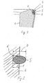
- FIG. 2 is shown in detail view of the clamping base 4 with the receiving device 6 designed as a groove.
- the bellows 2 is not yet mounted, so that the sealing element 5, which is clamped in the groove 6, protrudes beyond the clamping base 4.
- the groove depth t is less than the diameter D of the sealing element 5 and the radial extent of the sealing element 5, so that even with larger variations in shape or displacements, for example, the air spring piston 1, the sealing effect is maintained.
- the difference between the radial extent D of the sealing element 5 and the groove depth t about half of the radial extent D, alternative dimensions are possible and depend on the technical requirements.
- the sealing element 5 according to FIG. 2 is formed as an elastomeric ring with an oval cross-section, other cross-sectional shapes or configurations of the sealing elements are also provided.
Landscapes
- Engineering & Computer Science (AREA)
- General Engineering & Computer Science (AREA)
- Mechanical Engineering (AREA)
- Sealing Devices (AREA)
- Diaphragms And Bellows (AREA)
- Fluid-Damping Devices (AREA)
Abstract
Description
Die Erfindung betrifft eine Luftfeder gemäß dem Oberbegriff des Anspruchs 1.The invention relates to an air spring according to the preamble of
Aus der
Aus der
Aus der
Aus der
Problematisch bei der Befestigung eines Luftfederbalges an einem Klemmgrund ist einerseits die stabile Befestigung, andererseits die Gewährleistung der Druckdichtigkeit im Klemmbereich, insbesondere bei Temperaturschwankungen.The problem with the attachment of an air spring bellows on a clamping base on the one hand, the stable attachment, on the other hand ensuring the pressure tightness in the terminal area, especially in temperature fluctuations.
Aufgabe der vorliegenden Erfindung ist es, eine Luftfeder bereitzustellen, die bei einer stabilen Klemmung eine ausreichende Dichtigkeit im Klemmbereich bereitstellt.Object of the present invention is to provide an air spring, which provides a sufficient tightness in the clamping area with a stable clamping.
Erfindungsgemäß wird diese Aufgabe durch die kennzeichnenden Merkmale des Anspruchs 1 gelöst. Insbesondere bei großen Temperaturschwankungen wird die Druckdichtigkeit der Luftfeder sichergestellt, indem das zusätzliche, ggf. separate Dichtelement einen zusätzlichen Abdichteffekt bereitstellt. Durch die elastische Verformung des Dichtelementes auch bei großen Temperaturschwankungen und damit verbundenen Verformungen des Klemmgrundes bleibt die Druckdichtigkeit der Luftfeder unter allen Arbeitsbedingungen sichergestellt.According to the invention this object is achieved by the characterizing features of
Die Erfindung sieht vor, dass in dem Klemmgrund eine Aufnahmeeinrichtung für das Dichtelement angeordnet ist, um eine exakte Positionierung des Dichtelementes zu gewährleisten. Diese Aufnahmeeinrichtung ist als Nut ausgebildet, in die das Dichtelement eingeklemmt, eingeklebt oder in ihr verspannt ist. Die Aufnahmeeinrichtung ist somit eine Positioniereinrichtung für das Dichtelement. Neben der Ausgestaltung des Dichtelementes als O-Ring können auch Dichtelemente mit anderen Querschnittsformen, beispielsweise rechteckig oder oval eingesetzt werden. Als Werkstoffe für das Dichtelement können alle ausreichend elastischen Werkstoffe eingesetzt werden, beispielsweise Gummi, Polyurethan oder andere Elastomere.The invention provides that in the clamping base a receiving device for the sealing element is arranged to ensure an exact positioning of the sealing element. This receiving device is designed as a groove, in which the sealing element is clamped, glued or braced in it. The receiving device is thus a positioning device for the sealing element. In addition to the design of the sealing element as an O-ring and sealing elements with other cross-sectional shapes, such as rectangular or oval can be used. As materials for the sealing element all sufficiently elastic materials can be used, for example rubber, polyurethane or other elastomers.
Um sicherzustellen, dass der Klemmring sicher positioniert bleibt, ist der Klemmgrund vorteilhafterweise als Nut ausgebildet, so dass eine axiale Bewegung des Klemmringes aufgrund der an dem Klemmring anliegenden Nutwandungen des Klemmgrundes vermieden wird.To ensure that the clamping ring remains securely positioned, the clamping base is advantageously designed as a groove, so that an axial movement of the clamping ring is avoided due to the voltage applied to the clamping ring groove walls of the clamping base.
Insbesondere bei dünnen Luftfederbälgen ist die Erfindung vorteilhaft einzusetzen, da aufgrund der geringen Materialstärke nur ein geringes Maß an Nachgiebigkeit durch den Luftfederbalg an der Klemmstelle bereitsteht, um bei Temperaturschwankungen oder anderen Belastungen Verlagerungen oder Verformungen an der Klemmstelle auszugleichen und die Dichtigkeit der Luftfeder zu gewährleisten. Insbesondere bei Luftfedern in Personenkraftwagen mit einer Außenführung sind die Luftfederbälge besonders dünn ausgebildet, was die oben beschriebenen Probleme nach sich zieht. Das zusätzliche Dichtelement gewährleistet insbesondere bei dünnwandigen Luftfederbälgen eine gute Dichtigkeit der Klemmverbindung.In particular, with thin air spring bellows, the invention is advantageous to use because due to the low material thickness only a small degree of compliance by the air bag at the nip is ready to compensate for temperature fluctuations or other loads displacements or deformations at the nip and to ensure the tightness of the air spring. In particular, in air springs in passenger cars with an external guide the bellows are designed to be particularly thin, which entails the problems described above. The additional sealing element ensures a good tightness of the clamping connection, especially in the case of thin-walled air spring bellows.
Bei Ausbildung der Aufnahmeeinrichtung oder Positioniereinrichtung als Nut ist das Dichtelement vorteilhafterweise so ausgestaltet, dass das Dichtelement ausreichend radial nach außen übersteht, um die Dichtfunktion zu gewährleisten.When forming the receiving device or positioning device as a groove, the sealing element is advantageously designed so that the sealing element projects sufficiently radially outward to ensure the sealing function.
Die kann dadurch geschehen, dass die Tiefe der Nut nicht mehr als 2/3 des radialen Querschnittes des Dichtelementes beträgt, das Dichtelement also mit 1/3 seines Durchmessers radial nach außen übersteht. Im Einzelfall kann ein Überstand von ¼ des Durchmessers genügen, ebenfalls kann bei starken Formschwankungen oder hohen Drücken der Überstand ½ oder 2/3 des Durchmessers betragen.This can be done by the depth of the groove is not more than 2/3 of the radial cross-section of the sealing element, the sealing element thus projects with 1/3 of its diameter radially outward. In individual cases, a supernatant of ¼ of the diameter can be sufficient, also in case of strong shape fluctuations or high pressures, the supernatant be ½ or 2/3 of the diameter.
Nachfolgend wird ein Ausführungsbeispiel der Erfindung anhand der Figuren erläutert, in denen:
- Fig. 1 -
- eine Teilansicht einer Luftfeder in Schnittansicht; sowie
- Fig. 2 -
- eine Detailansicht der Luftfeder dargestellt ist.
- Fig. 1 -
- a partial view of an air spring in sectional view; such as
- Fig. 2 -
- a detail view of the air spring is shown.
In der
Eine Axialbewegung des Klemmringes 3 wird durch die nutförmige Ausbildung des Klemmgrundes 4 verhindert, wobei die Nutwandungen unterschiedlich dimensioniert sind. In dem Klemmgrund 4 selbst ist eine zumindest teilweise umlaufende Nut 6 ausgebildet, in die ein Dichtelement 5 eingelegt ist, um eine Abdichtung der Luftfeder sicherzustellen. Insbesondere bei Temperaturschwankungen wird durch das zusätzlich vorhandene Dichtelement 5 eine Verbesserung der Druckdichtigkeit im Klemmbereich gewährleistet. Das elastische Dichtelement 5 ist dabei so ausgebildet, dass die Elastizität auch bei großen Temperaturschwankungen und damit verbundenen Verformungen des Klemmgrundes 4 ausreichen, um die Druckdichtigkeit der Luftfeder sicherzustellen.An axial movement of the
Die Ausbildung der Aufnahmeeinrichtung 6 als Nut stellt die exakte Positionierung des Dichtelementes 5 sicher.The formation of the
Durch die Anordnung eines zusätzlichen Dichtelementes 5 wird neben der Verbesserung der Dichtigkeit erreicht, dass die Anforderungen an die Bearbeitung des Klemmgrundes 4 reduziert werden können. Hinsichtlich der Oberflächenbeschaffenheit, Rundheit und Geometrie des Klemmgrundes 4 können aufgrund des zusätzlichen Dichtelementes geringere Anforderungen gestellt werden, was einen Kostenvorteil mit sich bringt. Da die Oberfläche des Klemmgrundes 4 aufgrund des Vorhandenseins des zusätzlichen Dichtelementes 5 eine geringere Oberflächengüte aufweisen muss, um die gleiche Dichtigkeit zu gewährleisten, wird bei gleicher Klemmkraft des Klemmringes 3 eine höhere Festigkeit des Luftfederbalges 2 aufgrund der höheren Oberflächenrauhigkeit gewährleistet. Der Klemmbereich oder Klemmgrund 4 hätte sonst durch aufwendige Rändelverfahren zusätzlich aufgerauht werden müssen.The arrangement of an
Alternativ zu der Befestigung des Luftfederbalges 3 an einem Luftfederkolben 1 kann eine Befestigung auch an einem Luftfederdeckel oder entsprechend anderen Bauteilen einer Luftfeder vorgesehen sein.Alternatively to the attachment of the
Das Dichtelement 5 kann bei geeigneter Materialwahl in den Luftfederbalg 2 einvulkanisiert oder an ihm angeklebt sein, alternativ kann eine Integration in den Klemmgrund 4 bzw. in die Aufnahmeeinrichtung 6 durch Einkleben, Einklemmen, Verspannen oder Einspritzen erfolgen.The sealing
In der
Claims (7)
- Pneumatic spring, in particular for vehicles, with a pneumatic spring bellows (2) which is secured to a clamping bottom (4) designed as a groove via a clamping ring (3), an additional sealing element (5) and arranged between the pneumatic spring bellows (2) and the clamping bottom (4), characterized in that a reception device (6), designed as a groove, for the sealing element (5) is provided in the clamping bottom (4), into which reception device (6) the sealing element is introduced, the sealing element (5) being configured in such a way that it projects radially outwards sufficiently to ensure the sealing function.
- Pneumatic spring according to Claim 1, characterized in that the sealing element (5) is designed as an O-ring.
- Pneumatic spring according to Claim 1 or 2, characterized in that the sealing element (5) is produced from an elastic material, in particular an elastomer, rubber or polyurethane.
- Pneumatic spring according to one of the preceding claims, characterized in that the sealing element (5) is vulcanized into the pneumatic spring bellows (2) or is adhesively bonded to the pneumatic spring bellows (2).
- Pneumatic spring according to one of the preceding claims, characterized in that the sealing element (5) is secured to the clamping bottom (4), in particular is clamped, adhesively bonded or braced in the reception device (6).
- Pneumatic spring according to one of the preceding claims, characterized in that the clamping bottom (4) is formed on a pneumatic spring piston (6) or a pneumatic spring cover.
- Pneumatic spring according to one of the preceding claims, characterized in that the depth of the groove amounts to no more than 2/3 of the radial cross section (8) of the sealing element (5).
Applications Claiming Priority (2)
| Application Number | Priority Date | Filing Date | Title |
|---|---|---|---|
| DE10361089 | 2003-12-22 | ||
| DE10361089A DE10361089A1 (en) | 2003-12-22 | 2003-12-22 | air spring |
Publications (3)
| Publication Number | Publication Date |
|---|---|
| EP1548320A1 EP1548320A1 (en) | 2005-06-29 |
| EP1548320B1 EP1548320B1 (en) | 2006-09-13 |
| EP1548320B2 true EP1548320B2 (en) | 2010-01-20 |
Family
ID=34530385
Family Applications (1)
| Application Number | Title | Priority Date | Filing Date |
|---|---|---|---|
| EP04004291A Expired - Lifetime EP1548320B2 (en) | 2003-12-22 | 2004-02-26 | Air spring |
Country Status (4)
| Country | Link |
|---|---|
| US (1) | US20050133976A1 (en) |
| EP (1) | EP1548320B2 (en) |
| AT (1) | ATE339632T1 (en) |
| DE (2) | DE10361089A1 (en) |
Families Citing this family (5)
| Publication number | Priority date | Publication date | Assignee | Title |
|---|---|---|---|---|
| DE102005032193A1 (en) * | 2005-07-09 | 2007-01-11 | Carl Freudenberg Kg | System for attaching rolling lobe to connector in air springs comprises deformable locking ring on outside of lobe, O-ring being fitted between inner surface of lobe and connector |
| DE102006038807A1 (en) * | 2006-08-18 | 2008-02-21 | Continental Aktiengesellschaft | air spring |
| DE102009057339B4 (en) * | 2009-12-07 | 2013-03-28 | Mtu Onsite Energy Gmbh | Gas distribution device and fuel cell assembly with such a device |
| DE102012220853A1 (en) * | 2012-03-23 | 2013-09-26 | Continental Teves Ag & Co. Ohg | air spring |
| DE102014205288A1 (en) * | 2014-03-21 | 2015-11-12 | Contitech Luftfedersysteme Gmbh | Cold-resistant air spring device |
Citations (3)
| Publication number | Priority date | Publication date | Assignee | Title |
|---|---|---|---|---|
| DE8413300U1 (en) † | 1984-09-20 | Gold, Henning, Prof.Dr.Ing., 6530 Bingen | Pneumatic spring-damper unit | |
| DE19740981A1 (en) † | 1996-09-30 | 1998-04-02 | Phoenix Ag | Pneumatic cushion between two adjacent components made of strengthened tube |
| DE19907656A1 (en) † | 1999-02-23 | 2000-08-24 | Bayerische Motoren Werke Ag | Attachment of an air spring bellows to a support part |
Family Cites Families (8)
| Publication number | Priority date | Publication date | Assignee | Title |
|---|---|---|---|---|
| US155198A (en) * | 1874-09-22 | Improvement in self-closing faucets | ||
| US160368A (en) * | 1875-03-02 | Improvement in watch-case springs | ||
| DE2130215C3 (en) * | 1971-06-18 | 1974-01-10 | Fichtel & Sachs Ag, 8720 Schweinfurt | Bellows attachment for air springs or the like with a closed, concave-shaped clamping ring |
| US4787607A (en) * | 1986-09-24 | 1988-11-29 | The Firestone Tire & Rubber Company | Air spring having internal sealing band and method of installing same |
| DE4401770A1 (en) * | 1994-01-24 | 1995-08-03 | Fichtel & Sachs Ag | Self pumping suspension strut |
| US6264178B1 (en) * | 2000-06-13 | 2001-07-24 | The Goodyear Tire & Rubber Company | Molded air sleeves |
| DE10163818B4 (en) * | 2001-12-22 | 2020-08-20 | Contitech Luftfedersysteme Gmbh | Hose roll bellows spring |
| DE10207102B4 (en) * | 2002-02-20 | 2005-09-15 | Zf Sachs Ag | vibration |
-
2003
- 2003-12-22 DE DE10361089A patent/DE10361089A1/en not_active Withdrawn
-
2004
- 2004-02-26 AT AT04004291T patent/ATE339632T1/en not_active IP Right Cessation
- 2004-02-26 EP EP04004291A patent/EP1548320B2/en not_active Expired - Lifetime
- 2004-02-26 DE DE502004001469T patent/DE502004001469D1/en not_active Expired - Lifetime
- 2004-09-22 US US10/946,281 patent/US20050133976A1/en not_active Abandoned
Patent Citations (3)
| Publication number | Priority date | Publication date | Assignee | Title |
|---|---|---|---|---|
| DE8413300U1 (en) † | 1984-09-20 | Gold, Henning, Prof.Dr.Ing., 6530 Bingen | Pneumatic spring-damper unit | |
| DE19740981A1 (en) † | 1996-09-30 | 1998-04-02 | Phoenix Ag | Pneumatic cushion between two adjacent components made of strengthened tube |
| DE19907656A1 (en) † | 1999-02-23 | 2000-08-24 | Bayerische Motoren Werke Ag | Attachment of an air spring bellows to a support part |
Also Published As
| Publication number | Publication date |
|---|---|
| EP1548320A1 (en) | 2005-06-29 |
| US20050133976A1 (en) | 2005-06-23 |
| DE502004001469D1 (en) | 2006-10-26 |
| DE10361089A1 (en) | 2005-07-21 |
| ATE339632T1 (en) | 2006-10-15 |
| EP1548320B1 (en) | 2006-09-13 |
Similar Documents
| Publication | Publication Date | Title |
|---|---|---|
| EP2089637B1 (en) | Air spring device | |
| DE3419967C2 (en) | Elastic joint, coupling or the like | |
| EP2090801B1 (en) | Pneumatic spring rollIing bellows | |
| DE102018210854B4 (en) | Air spring strut with a torsionally flexible rotary seal and chassis with one | |
| DE2816742C2 (en) | ||
| EP2032870B1 (en) | Air spring with telescopic bellows | |
| EP2847487A1 (en) | Air spring and method for turning up an air spring bellows of an air spring | |
| EP1031756A2 (en) | Fastening of the rolling diaphragm of an air spring on a supporting member | |
| EP1548320B2 (en) | Air spring | |
| WO2015139854A1 (en) | Cold-resistant air spring device | |
| DE102010026002A1 (en) | Air spring for supporting chassis frame of passenger car, has connector designed as elastic bearing with elastomer padding, where elastic bearing has radial cylindrical edge in region of elastomer padding | |
| DE102012220204A1 (en) | Pneumatic spring module for vehicle i.e. motor car, has revolution piston arranged on surface of cylinder tube, shock absorber arranged on airtight rolling bellows, and piston rod fixed with revolution piston | |
| DE102006005459A1 (en) | Air spring with external guide | |
| DE19740981A1 (en) | Pneumatic cushion between two adjacent components made of strengthened tube | |
| DE19826480A1 (en) | Air sprung vehicle suspension with button or press-fitted elastomer component | |
| DE102017217041A1 (en) | Air strut with sliding contour shell | |
| EP0915266B1 (en) | Circular elastic bearing and its production method | |
| EP1106862B1 (en) | Tight mounting of an air spring bellow | |
| DE102017222588A1 (en) | air spring | |
| EP1736683B1 (en) | Tubular air bellow pneumatic springs | |
| EP1837211A1 (en) | Air spring device with radial seal | |
| DE102006038807A1 (en) | air spring | |
| DE102019212067A1 (en) | Air suspension bellows and method for producing such an air suspension bellows | |
| DE102020203165A1 (en) | Air spring with an external guide and a method for producing an air spring | |
| DE19913754B4 (en) | spring element |
Legal Events
| Date | Code | Title | Description |
|---|---|---|---|
| PUAI | Public reference made under article 153(3) epc to a published international application that has entered the european phase |
Free format text: ORIGINAL CODE: 0009012 |
|
| AK | Designated contracting states |
Kind code of ref document: A1 Designated state(s): AT BE BG CH CY CZ DE DK EE ES FI FR GB GR HU IE IT LI LU MC NL PT RO SE SI SK TR |
|
| AX | Request for extension of the european patent |
Extension state: AL LT LV MK |
|
| 17P | Request for examination filed |
Effective date: 20051129 |
|
| AKX | Designation fees paid |
Designated state(s): AT BE BG CH CY CZ DE DK EE ES FI FR GB GR HU IE IT LI LU MC NL PT RO SE SI SK TR |
|
| GRAP | Despatch of communication of intention to grant a patent |
Free format text: ORIGINAL CODE: EPIDOSNIGR1 |
|
| GRAS | Grant fee paid |
Free format text: ORIGINAL CODE: EPIDOSNIGR3 |
|
| GRAA | (expected) grant |
Free format text: ORIGINAL CODE: 0009210 |
|
| AK | Designated contracting states |
Kind code of ref document: B1 Designated state(s): AT BE BG CH CY CZ DE DK EE ES FI FR GB GR HU IE IT LI LU MC NL PT RO SE SI SK TR |
|
| PG25 | Lapsed in a contracting state [announced via postgrant information from national office to epo] |
Ref country code: IT Free format text: LAPSE BECAUSE OF FAILURE TO SUBMIT A TRANSLATION OF THE DESCRIPTION OR TO PAY THE FEE WITHIN THE PRESCRIBED TIME-LIMIT;WARNING: LAPSES OF ITALIAN PATENTS WITH EFFECTIVE DATE BEFORE 2007 MAY HAVE OCCURRED AT ANY TIME BEFORE 2007. THE CORRECT EFFECTIVE DATE MAY BE DIFFERENT FROM THE ONE RECORDED. Effective date: 20060913 Ref country code: SI Free format text: LAPSE BECAUSE OF FAILURE TO SUBMIT A TRANSLATION OF THE DESCRIPTION OR TO PAY THE FEE WITHIN THE PRESCRIBED TIME-LIMIT Effective date: 20060913 Ref country code: RO Free format text: LAPSE BECAUSE OF FAILURE TO SUBMIT A TRANSLATION OF THE DESCRIPTION OR TO PAY THE FEE WITHIN THE PRESCRIBED TIME-LIMIT Effective date: 20060913 Ref country code: NL Free format text: LAPSE BECAUSE OF FAILURE TO SUBMIT A TRANSLATION OF THE DESCRIPTION OR TO PAY THE FEE WITHIN THE PRESCRIBED TIME-LIMIT Effective date: 20060913 Ref country code: CZ Free format text: LAPSE BECAUSE OF FAILURE TO SUBMIT A TRANSLATION OF THE DESCRIPTION OR TO PAY THE FEE WITHIN THE PRESCRIBED TIME-LIMIT Effective date: 20060913 Ref country code: IE Free format text: LAPSE BECAUSE OF FAILURE TO SUBMIT A TRANSLATION OF THE DESCRIPTION OR TO PAY THE FEE WITHIN THE PRESCRIBED TIME-LIMIT Effective date: 20060913 Ref country code: FI Free format text: LAPSE BECAUSE OF FAILURE TO SUBMIT A TRANSLATION OF THE DESCRIPTION OR TO PAY THE FEE WITHIN THE PRESCRIBED TIME-LIMIT Effective date: 20060913 Ref country code: SK Free format text: LAPSE BECAUSE OF FAILURE TO SUBMIT A TRANSLATION OF THE DESCRIPTION OR TO PAY THE FEE WITHIN THE PRESCRIBED TIME-LIMIT Effective date: 20060913 |
|
| REG | Reference to a national code |
Ref country code: GB Ref legal event code: FG4D Free format text: NOT ENGLISH |
|
| REG | Reference to a national code |
Ref country code: CH Ref legal event code: EP |
|
| REG | Reference to a national code |
Ref country code: IE Ref legal event code: FG4D Free format text: LANGUAGE OF EP DOCUMENT: GERMAN |
|
| REF | Corresponds to: |
Ref document number: 502004001469 Country of ref document: DE Date of ref document: 20061026 Kind code of ref document: P |
|
| GBT | Gb: translation of ep patent filed (gb section 77(6)(a)/1977) |
Effective date: 20061101 |
|
| PG25 | Lapsed in a contracting state [announced via postgrant information from national office to epo] |
Ref country code: BG Free format text: LAPSE BECAUSE OF FAILURE TO SUBMIT A TRANSLATION OF THE DESCRIPTION OR TO PAY THE FEE WITHIN THE PRESCRIBED TIME-LIMIT Effective date: 20061213 Ref country code: SE Free format text: LAPSE BECAUSE OF FAILURE TO SUBMIT A TRANSLATION OF THE DESCRIPTION OR TO PAY THE FEE WITHIN THE PRESCRIBED TIME-LIMIT Effective date: 20061213 Ref country code: DK Free format text: LAPSE BECAUSE OF FAILURE TO SUBMIT A TRANSLATION OF THE DESCRIPTION OR TO PAY THE FEE WITHIN THE PRESCRIBED TIME-LIMIT Effective date: 20061213 |
|
| PG25 | Lapsed in a contracting state [announced via postgrant information from national office to epo] |
Ref country code: ES Free format text: LAPSE BECAUSE OF FAILURE TO SUBMIT A TRANSLATION OF THE DESCRIPTION OR TO PAY THE FEE WITHIN THE PRESCRIBED TIME-LIMIT Effective date: 20061224 |
|
| PG25 | Lapsed in a contracting state [announced via postgrant information from national office to epo] |
Ref country code: PT Free format text: LAPSE BECAUSE OF FAILURE TO SUBMIT A TRANSLATION OF THE DESCRIPTION OR TO PAY THE FEE WITHIN THE PRESCRIBED TIME-LIMIT Effective date: 20070226 |
|
| PG25 | Lapsed in a contracting state [announced via postgrant information from national office to epo] |
Ref country code: MC Free format text: LAPSE BECAUSE OF NON-PAYMENT OF DUE FEES Effective date: 20070228 |
|
| NLV1 | Nl: lapsed or annulled due to failure to fulfill the requirements of art. 29p and 29m of the patents act | ||
| ET | Fr: translation filed | ||
| REG | Reference to a national code |
Ref country code: IE Ref legal event code: FD4D |
|
| PLBI | Opposition filed |
Free format text: ORIGINAL CODE: 0009260 |
|
| 26 | Opposition filed |
Opponent name: CARL FREUDENBERG KG Effective date: 20070606 |
|
| PLAX | Notice of opposition and request to file observation + time limit sent |
Free format text: ORIGINAL CODE: EPIDOSNOBS2 |
|
| PLBB | Reply of patent proprietor to notice(s) of opposition received |
Free format text: ORIGINAL CODE: EPIDOSNOBS3 |
|
| BERE | Be: lapsed |
Owner name: CONTINENTAL A.G. Effective date: 20070228 |
|
| PG25 | Lapsed in a contracting state [announced via postgrant information from national office to epo] |
Ref country code: BE Free format text: LAPSE BECAUSE OF NON-PAYMENT OF DUE FEES Effective date: 20070228 |
|
| PG25 | Lapsed in a contracting state [announced via postgrant information from national office to epo] |
Ref country code: GR Free format text: LAPSE BECAUSE OF FAILURE TO SUBMIT A TRANSLATION OF THE DESCRIPTION OR TO PAY THE FEE WITHIN THE PRESCRIBED TIME-LIMIT Effective date: 20061214 |
|
| PG25 | Lapsed in a contracting state [announced via postgrant information from national office to epo] |
Ref country code: AT Free format text: LAPSE BECAUSE OF NON-PAYMENT OF DUE FEES Effective date: 20070226 |
|
| PG25 | Lapsed in a contracting state [announced via postgrant information from national office to epo] |
Ref country code: EE Free format text: LAPSE BECAUSE OF FAILURE TO SUBMIT A TRANSLATION OF THE DESCRIPTION OR TO PAY THE FEE WITHIN THE PRESCRIBED TIME-LIMIT Effective date: 20060913 |
|
| REG | Reference to a national code |
Ref country code: CH Ref legal event code: PL |
|
| PG25 | Lapsed in a contracting state [announced via postgrant information from national office to epo] |
Ref country code: LI Free format text: LAPSE BECAUSE OF NON-PAYMENT OF DUE FEES Effective date: 20080229 Ref country code: CH Free format text: LAPSE BECAUSE OF NON-PAYMENT OF DUE FEES Effective date: 20080229 |
|
| PG25 | Lapsed in a contracting state [announced via postgrant information from national office to epo] |
Ref country code: LU Free format text: LAPSE BECAUSE OF NON-PAYMENT OF DUE FEES Effective date: 20070226 Ref country code: CY Free format text: LAPSE BECAUSE OF FAILURE TO SUBMIT A TRANSLATION OF THE DESCRIPTION OR TO PAY THE FEE WITHIN THE PRESCRIBED TIME-LIMIT Effective date: 20060913 |
|
| PG25 | Lapsed in a contracting state [announced via postgrant information from national office to epo] |
Ref country code: TR Free format text: LAPSE BECAUSE OF FAILURE TO SUBMIT A TRANSLATION OF THE DESCRIPTION OR TO PAY THE FEE WITHIN THE PRESCRIBED TIME-LIMIT Effective date: 20060913 Ref country code: HU Free format text: LAPSE BECAUSE OF FAILURE TO SUBMIT A TRANSLATION OF THE DESCRIPTION OR TO PAY THE FEE WITHIN THE PRESCRIBED TIME-LIMIT Effective date: 20070314 |
|
| PUAH | Patent maintained in amended form |
Free format text: ORIGINAL CODE: 0009272 |
|
| STAA | Information on the status of an ep patent application or granted ep patent |
Free format text: STATUS: PATENT MAINTAINED AS AMENDED |
|
| 27A | Patent maintained in amended form |
Effective date: 20100120 |
|
| AK | Designated contracting states |
Kind code of ref document: B2 Designated state(s): AT BE BG CH CY CZ DE DK EE ES FI FR GB GR HU IE IT LI LU MC NL PT RO SE SI SK TR |
|
| REG | Reference to a national code |
Ref country code: ES Ref legal event code: FD2A Effective date: 20070227 |
|
| PGFP | Annual fee paid to national office [announced via postgrant information from national office to epo] |
Ref country code: IT Payment date: 20100220 Year of fee payment: 7 |
|
| REG | Reference to a national code |
Ref country code: DE Ref legal event code: R081 Ref document number: 502004001469 Country of ref document: DE Owner name: CONTINENTAL TEVES AG & CO. OHG, DE Free format text: FORMER OWNER: CONTINENTAL AKTIENGESELLSCHAFT, 30165 HANNOVER, DE Effective date: 20110414 |
|
| PG25 | Lapsed in a contracting state [announced via postgrant information from national office to epo] |
Ref country code: IT Free format text: LAPSE BECAUSE OF NON-PAYMENT OF DUE FEES Effective date: 20110226 |
|
| REG | Reference to a national code |
Ref country code: DE Ref legal event code: R082 Ref document number: 502004001469 Country of ref document: DE Representative=s name: GRAMM, LINS & PARTNER PATENT- UND RECHTSANWAEL, DE |
|
| REG | Reference to a national code |
Ref country code: FR Ref legal event code: PLFP Year of fee payment: 13 |
|
| PGFP | Annual fee paid to national office [announced via postgrant information from national office to epo] |
Ref country code: FR Payment date: 20160218 Year of fee payment: 13 Ref country code: GB Payment date: 20160217 Year of fee payment: 13 |
|
| GBPC | Gb: european patent ceased through non-payment of renewal fee |
Effective date: 20170226 |
|
| REG | Reference to a national code |
Ref country code: FR Ref legal event code: ST Effective date: 20171031 |
|
| PG25 | Lapsed in a contracting state [announced via postgrant information from national office to epo] |
Ref country code: FR Free format text: LAPSE BECAUSE OF NON-PAYMENT OF DUE FEES Effective date: 20170228 |
|
| PG25 | Lapsed in a contracting state [announced via postgrant information from national office to epo] |
Ref country code: GB Free format text: LAPSE BECAUSE OF NON-PAYMENT OF DUE FEES Effective date: 20170226 |
|
| PGFP | Annual fee paid to national office [announced via postgrant information from national office to epo] |
Ref country code: DE Payment date: 20180228 Year of fee payment: 15 |
|
| REG | Reference to a national code |
Ref country code: DE Ref legal event code: R119 Ref document number: 502004001469 Country of ref document: DE |
|
| PG25 | Lapsed in a contracting state [announced via postgrant information from national office to epo] |
Ref country code: DE Free format text: LAPSE BECAUSE OF NON-PAYMENT OF DUE FEES Effective date: 20190903 |