EP1548295A1 - Dispositif de fixation de deux pièces d'un véhicule automobile - Google Patents
Dispositif de fixation de deux pièces d'un véhicule automobile Download PDFInfo
- Publication number
- EP1548295A1 EP1548295A1 EP04300886A EP04300886A EP1548295A1 EP 1548295 A1 EP1548295 A1 EP 1548295A1 EP 04300886 A EP04300886 A EP 04300886A EP 04300886 A EP04300886 A EP 04300886A EP 1548295 A1 EP1548295 A1 EP 1548295A1
- Authority
- EP
- European Patent Office
- Prior art keywords
- piece
- parts
- serrage
- une
- clamping
- Prior art date
- Legal status (The legal status is an assumption and is not a legal conclusion. Google has not performed a legal analysis and makes no representation as to the accuracy of the status listed.)
- Granted
Links
Images
Classifications
-
- F—MECHANICAL ENGINEERING; LIGHTING; HEATING; WEAPONS; BLASTING
- F01—MACHINES OR ENGINES IN GENERAL; ENGINE PLANTS IN GENERAL; STEAM ENGINES
- F01N—GAS-FLOW SILENCERS OR EXHAUST APPARATUS FOR MACHINES OR ENGINES IN GENERAL; GAS-FLOW SILENCERS OR EXHAUST APPARATUS FOR INTERNAL-COMBUSTION ENGINES
- F01N13/00—Exhaust or silencing apparatus characterised by constructional features
- F01N13/18—Construction facilitating manufacture, assembly, or disassembly
- F01N13/1805—Fixing exhaust manifolds, exhaust pipes or pipe sections to each other, to engine or to vehicle body
- F01N13/1811—Fixing exhaust manifolds, exhaust pipes or pipe sections to each other, to engine or to vehicle body with means permitting relative movement, e.g. compensation of thermal expansion or vibration
- F01N13/1822—Fixing exhaust manifolds, exhaust pipes or pipe sections to each other, to engine or to vehicle body with means permitting relative movement, e.g. compensation of thermal expansion or vibration for fixing exhaust pipes or devices to vehicle body
-
- F—MECHANICAL ENGINEERING; LIGHTING; HEATING; WEAPONS; BLASTING
- F16—ENGINEERING ELEMENTS AND UNITS; GENERAL MEASURES FOR PRODUCING AND MAINTAINING EFFECTIVE FUNCTIONING OF MACHINES OR INSTALLATIONS; THERMAL INSULATION IN GENERAL
- F16B—DEVICES FOR FASTENING OR SECURING CONSTRUCTIONAL ELEMENTS OR MACHINE PARTS TOGETHER, e.g. NAILS, BOLTS, CIRCLIPS, CLAMPS, CLIPS OR WEDGES; JOINTS OR JOINTING
- F16B7/00—Connections of rods or tubes, e.g. of non-circular section, mutually, including resilient connections
- F16B7/18—Connections of rods or tubes, e.g. of non-circular section, mutually, including resilient connections using screw-thread elements
-
- B—PERFORMING OPERATIONS; TRANSPORTING
- B60—VEHICLES IN GENERAL
- B60K—ARRANGEMENT OR MOUNTING OF PROPULSION UNITS OR OF TRANSMISSIONS IN VEHICLES; ARRANGEMENT OR MOUNTING OF PLURAL DIVERSE PRIME-MOVERS IN VEHICLES; AUXILIARY DRIVES FOR VEHICLES; INSTRUMENTATION OR DASHBOARDS FOR VEHICLES; ARRANGEMENTS IN CONNECTION WITH COOLING, AIR INTAKE, GAS EXHAUST OR FUEL SUPPLY OF PROPULSION UNITS IN VEHICLES
- B60K13/00—Arrangement in connection with combustion air intake or gas exhaust of propulsion units
- B60K13/04—Arrangement in connection with combustion air intake or gas exhaust of propulsion units concerning exhaust
Definitions
- the present invention relates to an assembly for fixing two parts of a motor vehicle.
- the present invention can be implemented particularly in the case of fixing two pieces of the body of a motor vehicle, such as, for example, the stud support exhaust suspension and exhaust pad.
- Fixing the stud on its support is conventionally carried out by tightening with two screws.
- the support zone between the support and the stud is formed of a plane perpendicular to the direction of tightening. Both rooms being restrained to each other only by the existing frictional forces between the surfaces in contact, the zone of support between the two parts must to be maximum. The rotational locking of the two parts is ensured by the two clamping screws, both perpendicular to the bearing area.
- the purpose of the present invention is to propose a device for fixing two parts of a motor vehicle different from that described above.
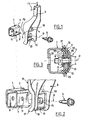
- the device of the invention comprises a first piece 1, a second piece 3 and a screw 5.
- the first piece is the stud support exhaust, the second part 3 being the exhaust pad.
- the support of pad 1 comprises, in a zone elastically deformable, a profile formed of a dihedron having two planar regions 7 forming between them an angle substantially equal to 90 °.
- Part 9 perpendicular to the clamping direction D has an opening 11 equipped with a welded nut (not visible in the figures) disposed on the face of the part 9 can not come into contact with the exhaust pad 3,
- the stud 3 comprises, in an elastically defensible zone, a complementary dihedral formed of two flat regions forming 13 between them an angle substantially equal to 90 °.
- a hole 15 is provided between the regions planes 13 so as to fix the two parts by clamping by means of the screw 5 and the welded nut.
- the assembly of the pieces is as follows. We fit pieces 1 and 3, the planar regions 7 and 13 bear against one another. We screw the screw 5 in the welded nut until elastic deformation of the parts profiles 1 and 3. It is also possible to fit both pieces while screwing the screw 5.
- the device further comprises a third piece 17 which has a first face 19 cooperating with the profile of the stud 3 and a second face 21 cooperating with the dihedron of the pad support 1.
- the parts 23 which comprise the planar regions that cooperate with the planar regions 9 and 13 form a angle substantially equal to 90 °; the flat regions 13 of the stud form between they an angle substantially equal to 88 °.
- the flat regions 7 form a angle as described in the first embodiment of the invention in FIG. 1.
- a perforation 25 allows the passage of the screw 5 to through the third piece 17.
- FIG. 3 shows the cooperation by blocking in abutment of different pieces.
- the use of a single screw 5 reduces the number of pieces and therefore the cost of parts and their assembly.
- the surface of support of the parts is reduced compared to the prior art since only the planar regions 9, 13 and 23 partially come into contact.
- the parts of different pieces perpendicular to the tightening direction D are distant each other. The thermal conduction of the whole is therefore limited.
Landscapes
- Engineering & Computer Science (AREA)
- General Engineering & Computer Science (AREA)
- Mechanical Engineering (AREA)
- Chemical & Material Sciences (AREA)
- Combustion & Propulsion (AREA)
- Connection Of Plates (AREA)
- Cooling, Air Intake And Gas Exhaust, And Fuel Tank Arrangements In Propulsion Units (AREA)
- Exhaust Silencers (AREA)
- Clamps And Clips (AREA)
- Automobile Manufacture Line, Endless Track Vehicle, Trailer (AREA)
Abstract
- une première pièce (1) et une seconde pièce (3) comportant chacune au moins une zone élastiquement déformable ;
- des moyens de fixation (5) desdites pièces par serrage selon une direction de serrage (D) ; et
- des moyens (7 ; 13) permettant d'éviter la rotation desdites pièces autour d'un axe parallèle à ladite direction de serrage (D). De manière caractéristique, selon l'invention, la première pièce (1) et la seconde pièce (3) présentent au moins dans ladite zone élastiquement déformable, des profils au moins partiellement complémentaires, aptes à coopérer par emboítement selon la direction de serrage (D), les profils au moins partiellement complémentaires étant emboítés et déformés de manière élastique lors du serrage.
Description
- une première pièce et une seconde pièce comportant chacune au moins une zone élastiquement déformable;
- des moyens de fixation, desdites pièces par serrage selon une direction de serrage ; et
- des moyens permettant d'éviter la rotation desdites pièces autour d'un axe parallèle à la direction de serrage. De manière caractéristique, selon l'invention, la première pièce et la seconde pièce présentent au moins dans la zone élastiquement déformable, des profils au moins partiellement complémentaires, aptes à coopérer par emboítement selon la direction de serrage, les profits au moins partiellement complémentaires étant emboítés et déformés de manière élastique lors du serrage. L'emboítement des profils permet une meilleure fixation des deux pièces, du fait de la formation de zones de blocage, où les deux pièces viennent en butée l'une sur l'autre. La déformation, élastique vient encore renforcer cette fixation, les deux pièces exerçant l'une sur l'autre des forces contraires qui tendent à augmenter l'action des moyens de serrage. A couple de serrage égal, les efforts supportes par le dispositif de l'invention sont supérieurs à ceux supportés par la fixation de l'art antérieur précédemment décrite. Par ailleurs, la fixation étant assurée par butée, elle est beaucoup moins tributaire du coefficient de frottement des zones en contact. Ce coefficient de frottement peut être modifié par des résidus d'huile issus de la fabrication des pièces ou par la détérioration du contact entre les deux pièces du fait de l'endurance.Le mode de réalisation des moyens permettant d'éviter la rotation n'est pas limité selon l'invention. Selon un mode de réalisation particulier, ces moyens comprennent au moins une région plane disposée sur chacune des pièces, les régions planes coopérant au moins partiellement, par appui de la fixation des pièces. La fixation en rotation est ainsi mise en oeuvre par frottement (appui et déformation élastique des régions planes) et par blocage du fait de la coopération par emboítement des profils.Selon une variante particulière, chacune des pièces comporte deux régions planes formant un dièdre, les dièdres étant complémentaires l'un de l'autre. Cette forme particulière est simple à réalisée et permet d'obtenir une bonne fixation par butée (blocage). Par ailleurs, cette forme « raide ») permet une plus faible remontée du bruit causé par le véhicule en mouvement dans la caisse. De plus, il est ainsi possible de limiter la surface d'appui entre les deux pièces (seules les régions planes sont au moins partiellement en appui l'une sur l'autre), sans diminuer la force de fixation, ce qui permet de réduire la conduction thermique de l'ensemble formé des pièces assemblées.Selon une variante particulière, la première pièce comporte deux régions planes formant un angle compris entre 89° et 91°.Selon une variante, la seconde pièce comporte deux régions planes formant un angle compris entre 87° et 91°.Selon un second mode de réalisation particulier, le dispositif de l'invention comporte une troisième pièce comprenant au moins une zone élastiquement déformable, apte à être insérée entre la première pièce et la seconde pièce ; cette troisième pièce comporte une première face apte à coopérer au moins partiellement par emboítement avec le profit de la première pièce et une seconde face apte à coopérer au moins partiellement par emboítement avec le profil de la seconde pièce.Les moyens de serrage ne sont pas limités selon l'invention. Il peut s'agir de crochets coopérant avec des anneaux ou de tout autre élément ou combinaison d'éléments permettant le serrage des pièces. Selon un mode de réalisation particulier, les moyens de fixation par serrage comportent une vis de fixation.Le matériau utilisé pour la réalisation des pièces du dispositif de l'invention n'est pas limitatif de l'invention. Les première, seconde et éventuellement troisième pièces peuvent être, réalisées, par exemple, en tôle d'acier ayant une épaisseur sensiblement comprise entre 1,5 mm et 4 mm. Dans ce cas, les pièces peuvent être formées par emboutissage et elles sont entièrement élastiquement déformables.Le dispositif de l'invention peut être utilisé pour la fixation de n'importe quelles pièces d'un véhicule automobile. Il est particulièrement avantageux pour la fixation du plot d'échappement d'un véhicule automobile. Dans ce cas, la première pièce est le support de plot de suspension d'échappement d'un véhicule automobile et la seconde pièce est le plot d'échappement.La présente invention, ses caractéristiques et les divers avantages qu'elle procure apparaítront mieux à la lecture de la description qui suit de deux exemples particuliers de réalisation de la présente invention et qui fait référence aux dessins annexés sur lesquels ;
- la figure 1 représente une vue en perspective d'un premier mode de réalisation du dispositif de l'invention ;
- la figure 2 représente un second mode de réalisation du dispositif de l'invention; et
- la figure 3 représente une vue en coupe selon la direction de serrage du dispositif de la figure 2.
Claims (9)
- Dispositif de fixation de deux pièces (1 ; 3) d'un véhicule automobile comportant :caractérisé en ce que ladite première pièce (1) et ladite seconde pièce (3) présentent au moins dans ladite zone élastiquement déformable, des profils au moins partiellement complémentaires, aptes à coopérer par emboítement selon ladite direction de serrage (D), lesdits profils au moins partiellement complémentaires étant emboítés et déformés de manière élastique lors du serrage.une première pièce (1) et une seconde pièce (3) comportant chacune au moins une zone élastiquement déformable ;des moyens de fixation (5) desdites pièces par serrage selon une direction de serrage (D) ; etdes moyens (7 ; 13) permettant d'éviter la rotation, desdites pièces autour d'un axe parallèle à ladite direction de serrage (D),
- Dispositif de fixation selon la revendication 1, caractérisé en ce que lesdits moyens permettant d'éviter la rotation desdites pièces selon un axe parallèle à ladite direction de serrage comprennent au moins une région plane (7 ; 13) disposée sur chacune desdites pièces, lesdites régions planes (7 ; 13) coopérant au moins partiellement par appui lors de la fixation desdites pièces.
- Dispositif de fixation selon la revendication 2, caractérisé en ce que chacune desdites pièces comportent deux régions planes (7 ; 13) formant un dièdre, lesdits dièdres étant complémentaires l'un de l'autre
- Dispositif de fixation selon la revendication 3, caractérisé en ce que ladite première pièce (1) comporte deux régions planes (7) formant un angle compris entre 89° et 91°.
- Dispositif de fixation selon la revendication 3 ou 4, caractérisé en ce que ladite seconde pièce comporte deux régions planes (13) formant un angle compris entre 87° et 91°.
- Dispositif de fixation selon l'une quelconque des revendications 1 à 5, caractérisé en ce qu'il comporte une troisième pièce (17) comprenant au moins une zone élastiquement déformable, apte à être insérée entre ladite première pièce et ladite seconde pièce, ladite troisième pièce (17) comporte une première face (21) apte à coopérer au moins partiellement par emboítement avec le profil de ladite première pièce (1) et une seconde face (23) apte à coopérer au moins partiellement par emboítement avec le profil de ladite seconde pièce (3).
- Ensemble selon l'une quelconque des revendications 1 à 6, caractérisé en ce que lesdits moyens de fixation par serrage comportent une vis de fixation (5).
- Dispositif de fixation selon l'une quelconque des revendications 1 à 7, caractérisé en ce que lesdites première, seconde et éventuellement troisième pièces (1; 3; 17) sont réalisées en tôle d'acier ayant une épaisseur sensiblement comprise entre 1,5 mm et 4 mm.
- Dispositif de fixation selon l'une quelconque des revendications 1 à 8, caractérise en ce que ladite première pièce (1) est le support de plot de suspension d'échappement d'un véhicule automobile, ladite seconde pièce (3) étant le plot d'échappement.
Applications Claiming Priority (2)
| Application Number | Priority Date | Filing Date | Title |
|---|---|---|---|
| FR0315307 | 2003-12-23 | ||
| FR0315307A FR2864180B1 (fr) | 2003-12-23 | 2003-12-23 | Dispositif de fixation de deux pieces d'un vehicule automobile |
Publications (2)
| Publication Number | Publication Date |
|---|---|
| EP1548295A1 true EP1548295A1 (fr) | 2005-06-29 |
| EP1548295B1 EP1548295B1 (fr) | 2006-10-04 |
Family
ID=34531344
Family Applications (1)
| Application Number | Title | Priority Date | Filing Date |
|---|---|---|---|
| EP04300886A Expired - Lifetime EP1548295B1 (fr) | 2003-12-23 | 2004-12-14 | Dispositif de fixation d'un plot de suspension déchappement sur un support du bas de caisse d'un véhicule automobile |
Country Status (5)
| Country | Link |
|---|---|
| EP (1) | EP1548295B1 (fr) |
| AT (1) | ATE341717T1 (fr) |
| DE (1) | DE602004002661T2 (fr) |
| ES (1) | ES2268600T3 (fr) |
| FR (1) | FR2864180B1 (fr) |
Cited By (1)
| Publication number | Priority date | Publication date | Assignee | Title |
|---|---|---|---|---|
| FR3060705A1 (fr) * | 2016-12-16 | 2018-06-22 | Valeo Systemes De Controle Moteur | Dispositif de maintien d'un organe par rapport a un support |
Citations (3)
| Publication number | Priority date | Publication date | Assignee | Title |
|---|---|---|---|---|
| FR1116468A (fr) * | 1954-11-17 | 1956-05-08 | Procédé d'assemblage de tubes | |
| GB1090200A (en) * | 1965-10-05 | 1967-11-08 | Gen Motors Corp | Motor vehicle exhaust pipe mounts |
| EP0479134A1 (fr) * | 1990-10-01 | 1992-04-08 | Al-Ko Kober Ag | Châssis pour véhicules à moteur ou remorques |
-
2003
- 2003-12-23 FR FR0315307A patent/FR2864180B1/fr not_active Expired - Fee Related
-
2004
- 2004-12-14 EP EP04300886A patent/EP1548295B1/fr not_active Expired - Lifetime
- 2004-12-14 DE DE602004002661T patent/DE602004002661T2/de not_active Expired - Lifetime
- 2004-12-14 ES ES04300886T patent/ES2268600T3/es not_active Expired - Lifetime
- 2004-12-14 AT AT04300886T patent/ATE341717T1/de not_active IP Right Cessation
Patent Citations (3)
| Publication number | Priority date | Publication date | Assignee | Title |
|---|---|---|---|---|
| FR1116468A (fr) * | 1954-11-17 | 1956-05-08 | Procédé d'assemblage de tubes | |
| GB1090200A (en) * | 1965-10-05 | 1967-11-08 | Gen Motors Corp | Motor vehicle exhaust pipe mounts |
| EP0479134A1 (fr) * | 1990-10-01 | 1992-04-08 | Al-Ko Kober Ag | Châssis pour véhicules à moteur ou remorques |
Cited By (1)
| Publication number | Priority date | Publication date | Assignee | Title |
|---|---|---|---|---|
| FR3060705A1 (fr) * | 2016-12-16 | 2018-06-22 | Valeo Systemes De Controle Moteur | Dispositif de maintien d'un organe par rapport a un support |
Also Published As
| Publication number | Publication date |
|---|---|
| EP1548295B1 (fr) | 2006-10-04 |
| FR2864180B1 (fr) | 2012-02-24 |
| DE602004002661D1 (de) | 2006-11-16 |
| ES2268600T3 (es) | 2007-03-16 |
| ATE341717T1 (de) | 2006-10-15 |
| DE602004002661T2 (de) | 2007-08-16 |
| FR2864180A1 (fr) | 2005-06-24 |
Similar Documents
| Publication | Publication Date | Title |
|---|---|---|
| EP2141380B1 (fr) | Ressort de guidage d'éléments de friction et frein à disque comportant au moins un tel ressort. | |
| EP3015368B1 (fr) | Dispositif de fixation d'un moteur d'aéronef, et aéronef correspondant | |
| EP2659157B1 (fr) | Plot de friction souple et garniture de frein pourvue d'un tel plot | |
| EP2821685A1 (fr) | Dispositif de serrage comprenant un collier et un manchon | |
| FR2930203A1 (fr) | Glissiere pour siege de vehicule automobile et procede d'assemblage d'une telle glissiere | |
| FR3133873A1 (fr) | Dispositif de blocage à déformation limitée pour un mécanisme d’ouverture d’une porte latérale de véhicule | |
| EP0499506B1 (fr) | Ecrou encagé à montage en aveugle sur des panneaux d'épaisseur variable | |
| FR2732425A1 (fr) | Dispositif amortisseur de torsion a sieges basculants de structure composite pour les ressorts, notamment pour vehicule automobile | |
| EP1548295B1 (fr) | Dispositif de fixation d'un plot de suspension déchappement sur un support du bas de caisse d'un véhicule automobile | |
| EP1013827A1 (fr) | Dispositif de fixation de rails | |
| FR3064508B1 (fr) | Dispositif de liaison entre deux toles metalliques | |
| EP3906971B1 (fr) | Dispositif de protection pour corde et systeme de protection | |
| FR3091915A1 (fr) | « Pièce métallique pour un moteur à combustion interne et ensemble comportant une telle pièce » | |
| FR3086693A1 (fr) | Cale pour turbomachine, ensemble pour turbomachine, turbomachine et procede associes | |
| EP3060418A1 (fr) | Trappe a filtre pour dispositif thérmique de véhicule automobile | |
| FR2949250A1 (fr) | Pont amortissant | |
| WO2018086918A1 (fr) | Dispositif de transmission mecanique | |
| WO2026027407A1 (fr) | Système de fixation sur un grillage en treillis | |
| FR3163314A1 (fr) | Garniture d’étanchéité pour poignée verticale de commande d’ouverture de portière. | |
| WO2023061787A1 (fr) | Ensemble de fixation d'un élément à fixer sur une paroi de support | |
| EP0424203B1 (fr) | Dispositif de maintien de tubes ou analogues | |
| FR3140286A1 (fr) | Dispositif de protection anti-feu pour un connecteur de câble | |
| EP1785635B1 (fr) | Système de fixation sur tôle mince | |
| FR2992699A1 (fr) | Element porteur destine a recevoir un dispositif de fixation par montage quart de tour | |
| FR3094061A1 (fr) | Joint d’étanchéité entre deux pièces automobiles |
Legal Events
| Date | Code | Title | Description |
|---|---|---|---|
| PUAI | Public reference made under article 153(3) epc to a published international application that has entered the european phase |
Free format text: ORIGINAL CODE: 0009012 |
|
| AK | Designated contracting states |
Kind code of ref document: A1 Designated state(s): AT BE BG CH CY CZ DE DK EE ES FI FR GB GR HU IE IS IT LI LT LU MC NL PL PT RO SE SI SK TR |
|
| AX | Request for extension of the european patent |
Extension state: AL BA HR LV MK YU |
|
| 17P | Request for examination filed |
Effective date: 20050726 |
|
| AKX | Designation fees paid |
Designated state(s): AT BE BG CH CY CZ DE DK EE ES FI FR GB GR HU IE IS IT LI LT LU MC NL PL PT RO SE SI SK TR |
|
| RTI1 | Title (correction) |
Free format text: ASSEMBLY FOR FASTENING AN EXHAUST SYSTEM SUSPENSION ELEMENT TO A SUPPORT OF THE UNDERBODY OF A MOTOR VEHICLE |
|
| GRAP | Despatch of communication of intention to grant a patent |
Free format text: ORIGINAL CODE: EPIDOSNIGR1 |
|
| GRAS | Grant fee paid |
Free format text: ORIGINAL CODE: EPIDOSNIGR3 |
|
| GRAA | (expected) grant |
Free format text: ORIGINAL CODE: 0009210 |
|
| AK | Designated contracting states |
Kind code of ref document: B1 Designated state(s): AT BE BG CH CY CZ DE DK EE ES FI FR GB GR HU IE IS IT LI LT LU MC NL PL PT RO SE SI SK TR |
|
| PG25 | Lapsed in a contracting state [announced via postgrant information from national office to epo] |
Ref country code: NL Free format text: LAPSE BECAUSE OF FAILURE TO SUBMIT A TRANSLATION OF THE DESCRIPTION OR TO PAY THE FEE WITHIN THE PRESCRIBED TIME-LIMIT Effective date: 20061004 Ref country code: SI Free format text: LAPSE BECAUSE OF FAILURE TO SUBMIT A TRANSLATION OF THE DESCRIPTION OR TO PAY THE FEE WITHIN THE PRESCRIBED TIME-LIMIT Effective date: 20061004 Ref country code: LT Free format text: LAPSE BECAUSE OF FAILURE TO SUBMIT A TRANSLATION OF THE DESCRIPTION OR TO PAY THE FEE WITHIN THE PRESCRIBED TIME-LIMIT Effective date: 20061004 Ref country code: FI Free format text: LAPSE BECAUSE OF FAILURE TO SUBMIT A TRANSLATION OF THE DESCRIPTION OR TO PAY THE FEE WITHIN THE PRESCRIBED TIME-LIMIT Effective date: 20061004 Ref country code: CZ Free format text: LAPSE BECAUSE OF FAILURE TO SUBMIT A TRANSLATION OF THE DESCRIPTION OR TO PAY THE FEE WITHIN THE PRESCRIBED TIME-LIMIT Effective date: 20061004 Ref country code: IT Free format text: LAPSE BECAUSE OF FAILURE TO SUBMIT A TRANSLATION OF THE DESCRIPTION OR TO PAY THE FEE WITHIN THE PRESCRIBED TIME-LIMIT;WARNING: LAPSES OF ITALIAN PATENTS WITH EFFECTIVE DATE BEFORE 2007 MAY HAVE OCCURRED AT ANY TIME BEFORE 2007. THE CORRECT EFFECTIVE DATE MAY BE DIFFERENT FROM THE ONE RECORDED. Effective date: 20061004 Ref country code: IE Free format text: LAPSE BECAUSE OF FAILURE TO SUBMIT A TRANSLATION OF THE DESCRIPTION OR TO PAY THE FEE WITHIN THE PRESCRIBED TIME-LIMIT Effective date: 20061004 Ref country code: SK Free format text: LAPSE BECAUSE OF FAILURE TO SUBMIT A TRANSLATION OF THE DESCRIPTION OR TO PAY THE FEE WITHIN THE PRESCRIBED TIME-LIMIT Effective date: 20061004 Ref country code: RO Free format text: LAPSE BECAUSE OF FAILURE TO SUBMIT A TRANSLATION OF THE DESCRIPTION OR TO PAY THE FEE WITHIN THE PRESCRIBED TIME-LIMIT Effective date: 20061004 Ref country code: AT Free format text: LAPSE BECAUSE OF FAILURE TO SUBMIT A TRANSLATION OF THE DESCRIPTION OR TO PAY THE FEE WITHIN THE PRESCRIBED TIME-LIMIT Effective date: 20061004 Ref country code: PL Free format text: LAPSE BECAUSE OF FAILURE TO SUBMIT A TRANSLATION OF THE DESCRIPTION OR TO PAY THE FEE WITHIN THE PRESCRIBED TIME-LIMIT Effective date: 20061004 |
|
| REG | Reference to a national code |
Ref country code: GB Ref legal event code: FG4D Free format text: NOT ENGLISH |
|
| REG | Reference to a national code |
Ref country code: CH Ref legal event code: EP |
|
| REG | Reference to a national code |
Ref country code: IE Ref legal event code: FG4D Free format text: LANGUAGE OF EP DOCUMENT: FRENCH |
|
| REF | Corresponds to: |
Ref document number: 602004002661 Country of ref document: DE Date of ref document: 20061116 Kind code of ref document: P |
|
| GBT | Gb: translation of ep patent filed (gb section 77(6)(a)/1977) |
Effective date: 20061120 |
|
| PG25 | Lapsed in a contracting state [announced via postgrant information from national office to epo] |
Ref country code: MC Free format text: LAPSE BECAUSE OF NON-PAYMENT OF DUE FEES Effective date: 20061231 |
|
| PG25 | Lapsed in a contracting state [announced via postgrant information from national office to epo] |
Ref country code: DK Free format text: LAPSE BECAUSE OF FAILURE TO SUBMIT A TRANSLATION OF THE DESCRIPTION OR TO PAY THE FEE WITHIN THE PRESCRIBED TIME-LIMIT Effective date: 20070104 Ref country code: BG Free format text: LAPSE BECAUSE OF FAILURE TO SUBMIT A TRANSLATION OF THE DESCRIPTION OR TO PAY THE FEE WITHIN THE PRESCRIBED TIME-LIMIT Effective date: 20070104 Ref country code: SE Free format text: LAPSE BECAUSE OF FAILURE TO SUBMIT A TRANSLATION OF THE DESCRIPTION OR TO PAY THE FEE WITHIN THE PRESCRIBED TIME-LIMIT Effective date: 20070104 |
|
| PG25 | Lapsed in a contracting state [announced via postgrant information from national office to epo] |
Ref country code: IS Free format text: LAPSE BECAUSE OF FAILURE TO SUBMIT A TRANSLATION OF THE DESCRIPTION OR TO PAY THE FEE WITHIN THE PRESCRIBED TIME-LIMIT Effective date: 20070204 |
|
| PG25 | Lapsed in a contracting state [announced via postgrant information from national office to epo] |
Ref country code: PT Free format text: LAPSE BECAUSE OF FAILURE TO SUBMIT A TRANSLATION OF THE DESCRIPTION OR TO PAY THE FEE WITHIN THE PRESCRIBED TIME-LIMIT Effective date: 20070316 |
|
| REG | Reference to a national code |
Ref country code: ES Ref legal event code: FG2A Ref document number: 2268600 Country of ref document: ES Kind code of ref document: T3 |
|
| NLV1 | Nl: lapsed or annulled due to failure to fulfill the requirements of art. 29p and 29m of the patents act | ||
| REG | Reference to a national code |
Ref country code: IE Ref legal event code: FD4D |
|
| PLBE | No opposition filed within time limit |
Free format text: ORIGINAL CODE: 0009261 |
|
| STAA | Information on the status of an ep patent application or granted ep patent |
Free format text: STATUS: NO OPPOSITION FILED WITHIN TIME LIMIT |
|
| 26N | No opposition filed |
Effective date: 20070705 |
|
| PG25 | Lapsed in a contracting state [announced via postgrant information from national office to epo] |
Ref country code: GR Free format text: LAPSE BECAUSE OF FAILURE TO SUBMIT A TRANSLATION OF THE DESCRIPTION OR TO PAY THE FEE WITHIN THE PRESCRIBED TIME-LIMIT Effective date: 20070105 |
|
| PG25 | Lapsed in a contracting state [announced via postgrant information from national office to epo] |
Ref country code: EE Free format text: LAPSE BECAUSE OF FAILURE TO SUBMIT A TRANSLATION OF THE DESCRIPTION OR TO PAY THE FEE WITHIN THE PRESCRIBED TIME-LIMIT Effective date: 20061004 |
|
| PG25 | Lapsed in a contracting state [announced via postgrant information from national office to epo] |
Ref country code: HU Free format text: LAPSE BECAUSE OF FAILURE TO SUBMIT A TRANSLATION OF THE DESCRIPTION OR TO PAY THE FEE WITHIN THE PRESCRIBED TIME-LIMIT Effective date: 20070405 Ref country code: TR Free format text: LAPSE BECAUSE OF FAILURE TO SUBMIT A TRANSLATION OF THE DESCRIPTION OR TO PAY THE FEE WITHIN THE PRESCRIBED TIME-LIMIT Effective date: 20061004 Ref country code: LU Free format text: LAPSE BECAUSE OF NON-PAYMENT OF DUE FEES Effective date: 20061214 |
|
| PG25 | Lapsed in a contracting state [announced via postgrant information from national office to epo] |
Ref country code: CY Free format text: LAPSE BECAUSE OF FAILURE TO SUBMIT A TRANSLATION OF THE DESCRIPTION OR TO PAY THE FEE WITHIN THE PRESCRIBED TIME-LIMIT Effective date: 20061004 |
|
| REG | Reference to a national code |
Ref country code: CH Ref legal event code: PL |
|
| PG25 | Lapsed in a contracting state [announced via postgrant information from national office to epo] |
Ref country code: LI Free format text: LAPSE BECAUSE OF NON-PAYMENT OF DUE FEES Effective date: 20081231 Ref country code: CH Free format text: LAPSE BECAUSE OF NON-PAYMENT OF DUE FEES Effective date: 20081231 |
|
| PGFP | Annual fee paid to national office [announced via postgrant information from national office to epo] |
Ref country code: BE Payment date: 20111229 Year of fee payment: 8 |
|
| BERE | Be: lapsed |
Owner name: RENAULT S.A.S. Effective date: 20121231 |
|
| PG25 | Lapsed in a contracting state [announced via postgrant information from national office to epo] |
Ref country code: BE Free format text: LAPSE BECAUSE OF NON-PAYMENT OF DUE FEES Effective date: 20121231 |
|
| REG | Reference to a national code |
Ref country code: FR Ref legal event code: PLFP Year of fee payment: 12 |
|
| REG | Reference to a national code |
Ref country code: FR Ref legal event code: PLFP Year of fee payment: 13 |
|
| REG | Reference to a national code |
Ref country code: FR Ref legal event code: PLFP Year of fee payment: 14 |
|
| PGFP | Annual fee paid to national office [announced via postgrant information from national office to epo] |
Ref country code: GB Payment date: 20181218 Year of fee payment: 15 |
|
| PGFP | Annual fee paid to national office [announced via postgrant information from national office to epo] |
Ref country code: ES Payment date: 20190124 Year of fee payment: 15 |
|
| PGFP | Annual fee paid to national office [announced via postgrant information from national office to epo] |
Ref country code: DE Payment date: 20191210 Year of fee payment: 16 |
|
| GBPC | Gb: european patent ceased through non-payment of renewal fee |
Effective date: 20191214 |
|
| PG25 | Lapsed in a contracting state [announced via postgrant information from national office to epo] |
Ref country code: GB Free format text: LAPSE BECAUSE OF NON-PAYMENT OF DUE FEES Effective date: 20191214 |
|
| REG | Reference to a national code |
Ref country code: ES Ref legal event code: FD2A Effective date: 20210601 |
|
| REG | Reference to a national code |
Ref country code: DE Ref legal event code: R119 Ref document number: 602004002661 Country of ref document: DE |
|
| PG25 | Lapsed in a contracting state [announced via postgrant information from national office to epo] |
Ref country code: ES Free format text: LAPSE BECAUSE OF NON-PAYMENT OF DUE FEES Effective date: 20191215 |
|
| PG25 | Lapsed in a contracting state [announced via postgrant information from national office to epo] |
Ref country code: DE Free format text: LAPSE BECAUSE OF NON-PAYMENT OF DUE FEES Effective date: 20210701 |
|
| PGFP | Annual fee paid to national office [announced via postgrant information from national office to epo] |
Ref country code: FR Payment date: 20211224 Year of fee payment: 18 |
|
| PG25 | Lapsed in a contracting state [announced via postgrant information from national office to epo] |
Ref country code: FR Free format text: LAPSE BECAUSE OF NON-PAYMENT OF DUE FEES Effective date: 20221231 |