EP1548201B1 - Vibrationsisolierendes bausystem - Google Patents
Vibrationsisolierendes bausystem Download PDFInfo
- Publication number
- EP1548201B1 EP1548201B1 EP04029896A EP04029896A EP1548201B1 EP 1548201 B1 EP1548201 B1 EP 1548201B1 EP 04029896 A EP04029896 A EP 04029896A EP 04029896 A EP04029896 A EP 04029896A EP 1548201 B1 EP1548201 B1 EP 1548201B1
- Authority
- EP
- European Patent Office
- Prior art keywords
- silent block
- construction system
- silent
- rubber
- block
- Prior art date
- Legal status (The legal status is an assumption and is not a legal conclusion. Google has not performed a legal analysis and makes no representation as to the accuracy of the status listed.)
- Expired - Lifetime
Links
- 238000010276 construction Methods 0.000 title claims abstract description 25
- 238000013016 damping Methods 0.000 title abstract 2
- 229920001971 elastomer Polymers 0.000 claims abstract description 39
- 238000007667 floating Methods 0.000 claims abstract description 15
- 239000000463 material Substances 0.000 claims abstract description 6
- 239000002184 metal Substances 0.000 claims description 47
- 238000009413 insulation Methods 0.000 abstract description 2
- 230000004888 barrier function Effects 0.000 abstract 1
- 230000005540 biological transmission Effects 0.000 abstract 1
- 239000000806 elastomer Substances 0.000 abstract 1
- 238000009432 framing Methods 0.000 abstract 1
- 229910000831 Steel Inorganic materials 0.000 description 2
- 230000008878 coupling Effects 0.000 description 2
- 238000010168 coupling process Methods 0.000 description 2
- 238000005859 coupling reaction Methods 0.000 description 2
- 238000009434 installation Methods 0.000 description 2
- 239000010959 steel Substances 0.000 description 2
- 101100437784 Drosophila melanogaster bocks gene Proteins 0.000 description 1
- 208000027418 Wounds and injury Diseases 0.000 description 1
- 238000005452 bending Methods 0.000 description 1
- 230000006378 damage Effects 0.000 description 1
- 238000005034 decoration Methods 0.000 description 1
- 230000002708 enhancing effect Effects 0.000 description 1
- 208000014674 injury Diseases 0.000 description 1
- 238000000034 method Methods 0.000 description 1
- 230000036544 posture Effects 0.000 description 1
- 230000002265 prevention Effects 0.000 description 1
Images


Classifications
-
- E—FIXED CONSTRUCTIONS
- E04—BUILDING
- E04B—GENERAL BUILDING CONSTRUCTIONS; WALLS, e.g. PARTITIONS; ROOFS; FLOORS; CEILINGS; INSULATION OR OTHER PROTECTION OF BUILDINGS
- E04B9/00—Ceilings; Construction of ceilings, e.g. false ceilings; Ceiling construction with regard to insulation
- E04B9/18—Means for suspending the supporting construction
- E04B2009/186—Means for suspending the supporting construction with arrangements for damping vibration
Definitions
- the present description refers, as its title indicates, to a safe construction system for fixed or removable panels and false ceilings or those of a similar type used in the building industry in general, characterised by the fact that in the proposed system the assembly of a fixed panel is carried out by means of a isolator screwed to a wall and, between adjoining panels, by means of a floating isolator formed by a silent block with or without a spring, including one or more metal "L" shaped angle braces that are housed between the silent block system by means of a through screw and counter nuts, forming a compact block.
- the panels are attached to the "L" shaped angle braces by means of fixing elements, enhancing thermal and acoustic insulation.
- the object of the invention is to achieve a construction system that provides optimum safety guarantees in the coupling of the different elements that it comprises.
- Removable panels are secured using a wall isolator that comprises a metal surface with a vulcanised rubber silent block that remains screwed to a wall, at the same time incorporating a metal angle brace riveted to the silent block.
- a panel can be installed on the aforementioned angle brace by means of the orifices for this purpose, the main disadvantage of this device being its safety due to its poor performance in the event of a fire given the fact that the elements that it comprises do not maintain the structure in a block, with the added disadvantage that if a certain pressure is exerted the structure deforms readily.
- EP-A-0 060 567 discloses an isolator intended for the attachment of wiring or piping, fittings therefore or of other components on ceilings or walls. Such isolator is made using one U-shaped brace with one side of the U fitted to the ceiling by means of a silent block and a screw, and the other side of the U having a screw and nuts for connecting the wiring or piping.
- a different embodiment comprises one silent block which goes through a screw and a brace, being fitted to a wall by means of a screw or a nail.
- DE 299 11 747 discloses an isolator which comprises only one piece of rubber screwed to a wall by means of a screw which goes longitudinally across the piece of rubber.
- Other embodiments are fitted inserting a brace into a boss which runs around the external surface of the piece of rubber, the brace being, in turn, fitted to a surface by means of screws or nails.
- FR-A-2 831 572 describes an isolator intended for hanging steel sections from the ceiling. It comprises a plate assembly for attaching to the steel section and one rubber silent block. The fitting to the ceiling is provided with a threaded section which allows for height calibration.
- US 2003/0066261 discloses an isolator intended for ceiling frameworks which comprises a silent block, a bracket and a threaded rod.
- the threaded rod is connected to the silent block by means of an insert embedded in the rubber silent block, the bracket, in turn, being attached to the silent block by means of an external boss.
- the bracket is obtained simply bending a cut-out blank.
- the safety system for the attachment of fixed or removable panels basically comprises two types of isolators: a wall isolator and a floating isolator.
- the present construction system comprises a base made of die-cut plate with orifices to screw to a wall, forming a compact block by means of a though screw that carries out its torque on a screwed orifice in the base itself, including a silent block that houses, in its middle part, an "L" shaped angle brace with several orifices for the attachment of the panel using fixing means, with the possibility of using a simple drill.
- the wall isolator with a spring has a similar structure, the only difference being the silent blocks, which have a housing to accommodate the spring.
- the floating isolator (for panel to panel attachment) comprises two opposing silent blocks separated by a central silent block; the silent blocks at both ends including an "L" shaped angle brace, forming a compact block by means of a through screw, that exerts its torque on a counter nut. These panels are installed in the same way as described in the previous case.
- the components of the wall isolator with a rubber silent block are a die-cut metal base that is circular at the centre and narrows at the top and bottom, both ends being radially finished off incorporating a perforation of a smaller diameter in its geometric centre.
- This base is fitted to the wall by means of screws and washers.
- a rubber silent block that is basically cylindrical, its centre part being wider and formed by a spoke, both ends being narrower and straight, one end adjoining the metal base and the other the rubber silent block, formed by a cone trunk, that, at its narrowest end, has a boss and a housing box for a bent L-shaped metal angle brace on which the fixed or removable panels are Installed by means of fixing elements, through a plurality of equidistant perforations on said angle brace. All of the silent blocks have a through perforation at their geometric centre to allow the clamping screw to pass through.
- the floating isolator with the rubber silent block is formed by two "L"-shaped metal angle braces, each of which having a silent block formed by a cone trunk, that, in its narrowest part, has a boss and hou5ing box between which there is another cylindrical rubber silent block Whose centre part is wider and formed by a spoke, both of the narrower ends remaining straight.
- the fixed or removable panels are installed on bent L-shaped metal angle braces by means of fixing elements, through a plurality of equidistant perforations on said angle braces. All of the silent blocks have a through perforation at their geometric centre to allow the clamping screw to pass through.
- the components of the wall isolator with a rubber silent block and spring are a die-cut metal base that is circular at the centre and narrows at the top and bottom, both ends being radially finished off incorporating a perforation of a smaller diameter at its geometric centre.
- This base is tatted to the wall by means of screws and washers.
- Both ends, of a smaller diameter, comprise a straight section, a hemispherical boss and a housing box for a bent L-shaped metal angle brace, onto which the fixed or removable panels are installed by means of fixing elements, through a plurality of equidistant perforations on said angle brace.
- the opposite end Whilst one end of the aforementioned silent block remains adjoining the metal base, the opposite end, of the same design, houses a spring that in turn is centred on another cylindrical rubber silent block formed by a larger diameter straight section and a section of a smaller diameter that has a straight section, a hemispherical boss and a housing box in which the apposite endow the spring is housed.
- All of the silent blocks have a through perforation at their geometric centre to allow the clamping screw to pass through. All of this forms a compact block by means of a through screw screwed to the metal base. It is installed with a flat washer to enhance the screw torque.
- the floating isolator with rubber silent block and springs comprises two "L"-shape metal angle braces, each of which has a cylindrical silent block, the centre part of which is of a larger diameter. Both ends, of a smaller diameter comprise a straight section, a hemispherical boss and a housing box between which there is another cylindrical rubber silent block, the centre part being wider and formed by a spoke, both of the narrower ends remaining straight.
- the opposite end Whilst one end of the aforementioned silent block remains adjoining the metal base, the opposite end, of the same design, houses a spring that in turn is centred on another cylindrical rubber silent block formed by a short, larger diameter, straight section and a section of a smaller diameter that has a straight section, a hemispherical boss and a housing box in which the opposite end of the spring is housed.
- the fixed or removable panels are installed on the bent L-shaped metal angle braces by means of fixing elements, through a plurality of equidistant perforations on said angle braces, All of the silent bocks have a through perforation at their geometric centre, to allow the clamping screw to pass through.
- the initial step is to screw the isolators to the wall and on them the corresponding panels, so that to continue prolonging the wall, the floating isolators must be used, attaching, in this way, as many panels as are needed.
- This safe construction system presented provides, in relation to the fixing of panels, numerous advantages over the systems currency available, having a highly effective fire performance in the case of fixed or removable panels, given that, since the system is formed by a compact block by means of a screw that fixes the whole assembly together, in the event of fire the structure will never collapse inwards into the premises, thus preventing, as for as is possible, injury to persons.
- Another important common advantage of the safe construction system is the reduction of assembly times, considerably redudng costs and increasing productivity as well as favouring handling during assembly without fitters having to adopt forced postures, complying in this way with the current legislation on the prevention of risks at work.
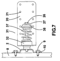
- the wall isolator (1) with rubber silent block, basically comprises a die-cut laminar metal base (2) that is Circular in its centre part, narrowing at the top (4) and bottom (5) both ends being radially finished off (6) incorporating a perforation (7) of a smaller diameter in its geometric centre; this base is installed on a walt (8) by means of screws (9) and washers (10).
- the centre part (11) is notably higher due to the spokes (12) that form it, incorporating a threaded perforation (13) at its geometric centre.
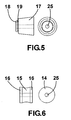
- a rubber silent block (14) Centred on the central part (11) of the metal base (2) there is a rubber silent block (14), that is basically cylindrical its central part (15) being wider and formed by an interior spoke, both narrower ends (16) remaining straight.
- a rubber silent block (17) During mounting one end is fitted adjoining the metallic base (2) and the other end adjoining another rubber silent block (17), of a cone trunk shape, with a boss (18) at its narrowest point and a smaller diameter housing box (19), to house a bent t-shaped metal angle brace (20), on which the fixed or removable panels am instated by means of fixing elements though a plurality of equidistant perforation (21) located along the top and bottom part.
- the angle brace (20) is made of thin laminar plate and of a rectangular shape, the edges (22) of its free end being rounded, the opposite end (23), of a reduced length and bent to an "L" shape, with an orifice (24) at its centre and the edges (22) of its free end being rounded.
- the silent block (17) remains secured in the angle brace (20) when the boss (18) is inserted into the orifice (24), maintaining a slight pressure and remaining in position in the box (19).
- All of the silent blocks have a through perforation (25) located at their geometric centre to allow a clamping screw (26) to pass through, producing a compact block when screwed to the metal base (2), a flat washer (27) being fitted to enhance the screw torque.
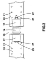
- the floating isolator (28) with rubber silent black is basically formed by two metal angle braces (20) bent in an L-shape, each of which includes a silent block (17), between both of these there is another cylindrical rubber silent block (14).
- the fixed or removable panels are installed on the metal angle braces (20) by means of fixing elements through a plurality of equidistant perforations (21).
- All of the silent blocks have a through perforation (25) at their geometric centre to allow a clamping screw (29) to pass through, producing a compact block when screwed to a counter nut (30), flat washers (27) being fitted to enhance the tightening torque
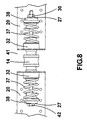
- the wall isolator (31), with rubber silent block and spring is basically formed by a die-cut laminar metal base (2) and it is installed on a wall (8) by means of screws (9) and washes (10).
- a robber silent block that is basically cylindrical, its central part (33) having a larger diameter; both ends being equal and of a smaller diameter comprise a straight section (34), a hemispherical boss (35) and a housing box (36) to accommodate a bent L-shaped metal angle brace (20).
- the opposite end Whilst one end (34) of the aforementioned silent block (32) remains adjoining the metal base (2), the opposite end, formed in the same way, houses a spring (37) that, in turn, is centred on another cylindrical rubber silent block (38), formed by a short straight section (39) of a larger diameter, with one end formed by another short straight section (40) of a smaller diameter and the opposite end, of a smaller diameter, having a straight section (34), a hemispherical boss (35) and a housing box (36) in which the opposite end of the spring (37) is housed.
- a spring that, in turn, is centred on another cylindrical rubber silent block (38), formed by a short straight section (39) of a larger diameter, with one end formed by another short straight section (40) of a smaller diameter and the opposite end, of a smaller diameter, having a straight section (34), a hemispherical boss (35) and a housing box (36) in which the opposite end of the spring (37) is housed.
- the silent block (32) remains secured in the angle brace (20) when the hemispherical boss (35) is inserted into the orifice (24), maintaining a slight pressure, remaining in position in the box (36), the spring (37) then remains positioned between the box (36) and the hemispherical boss (35)
- All of the silent blocks have a through perforation (25) at their geometric center to allow a clamping screw (26) to pass through, providing a compact black when screwed to the metal base (2), a flat washer (27) being fitted to enhance the tightening torque.
- the floating isolator (41), with rubber silent biotic and springs, basically comprises two bent Leaped metal angle braces (20), each one of which has a silent block (32), between each of these there is another cylindrical rubber silent block (14), in turn each silent block (32) takes a spring (37) housing its opposite end in a silent block (38).
- All of the silent blocks have a through perforation (25) at their geometric centre to allow a clamping screw (42) to pass through, providing a compact block when screwed to a counter nut (30), being fitted with flat washers (27) to enhance the tightening torque.
Landscapes
- Engineering & Computer Science (AREA)
- Architecture (AREA)
- Physics & Mathematics (AREA)
- Electromagnetism (AREA)
- Civil Engineering (AREA)
- Structural Engineering (AREA)
- Building Environments (AREA)
- Buildings Adapted To Withstand Abnormal External Influences (AREA)
Claims (13)
- - Ein Bausystem zum Zusammenbau von befestigten oder entfernbaren Bauplatten und Zwischendecken oder solchen ähnlicher Art, die im Allgemeinen in der Baubranche zum Einsatz kommen, und wo der Zusammenbau einen Wandisolator (1) enthält, der an eine Wand angeschraubt werden kann. Dieser ist dadurch gekennzeichnet, dass für das Zusammenfügen von anliegenden Platten, das Bausystem zusätzlich einen eingehängten Isolator (28) enthält, wobei der Wandisolator (1) aus einer ausgestanzten metallischen Lamellenunterlage (2) zur Anbringung an die Wand und einem Silentbloc (14) besteht, der vorzugsweise aus Gummimaterial bestehen soll, das die metallische Unterlage (2) mit dem anderen Ende vom besagten Silentbloc (14) verbindet. Dieser grenzt an eine L-förmige metallische Klammer (20) an, worin eine Spannschraube (26) durch die metallische Unterlage (2), den Silentbloc (14) und die L-förmige metallische Klammer (20) hindurchgeht. Ebenso enthält der eingehängte Isolator (28) zwei weitere L-förmige metallische Klammern (20), wovon jede einen Silenbloc (17) enthält, der vorzugsweise aus Gummi bestehen soll, mit einem weiteren Silentbloc (14) zwischen den beiden weiteren L-förmigen metallischen Klammern (20). Darin durchdringt eine Spannschraube (29) die beiden weiteren L-förmigen metallischen Klammern (20) und die drei Silentblocs (14, 17), wodurch der Struktur ermöglicht wird in ihrer Position zu verharren, ohne einzustürzen, falls ein Feuer ausbricht.
- - Ein Bausystem, in Übereinstimmung mit dem vorausgegangenen Patentanspruch, worin das besagte andere Ende vom erwähnten Silentbloc (14) an einen weiteren Silentbloc (17) angrenzt, der vorzugsweise aus Gummi sein soll und auf der besagten metallischen Winkelklammer in L-Form (20) untergebracht ist, und worin eine Schraube (26) in eine Öffnung (13) der Unterlage (2) sowie Unterlegscheibe (27) eingeschraubt ist.
- - Ein Bausystem, in Übereinstimmung mit den vorausgegangenen Anträgen, wo die Spannschraube (29) des schwebenden Isolators (28) an eine Gegenmutter (30) und zwei Unterlegscheiben (27) angeschraubt ist.
- - Ein Bausystem, in Übereinstimmung mit dem Patentanspruch 1 oder 2, wo der Wandisolator (31) eine Feder (37) beinhaltet, die zwischen dem Silentbloc (32) und einem weiteren Silentbloc (38) platziert ist, der vorzugsweise aus Gummi sein sollte. Hier wird eine weitere Spannschraube (26) in eine Öffnung (13) der Unterlage (2) und eine Unterlegescheibe (27) eingeschraubt.
- - Ein Bausystem, in Übereinstimmung mit den vorausgegangenen Patentansprüche, wo jeder Silentbloc (32) des schwebenden Isolators (41), der die beiden L-förmigen metallischen Winkelklammern (20) aufnimmt, über eine Feder (37) verfügt, deren gegenüberliegendes Ende in einem weiteren Silentbloc (38) untergebracht ist, wo die Spannschraube (42) an eine Gegenmutter (30) und zwei Unterlegscheiben (27) geschraubt ist.
- - Ein Bausystem, in Übereinstimmung mit den vorausgegangenen Patentansprüche, wo die ausgestanzte metallische Lamellenunterlage (2) in der Mitte (11) durch eine Rundform gebildet wird, und das Oberteil (1) und Unterteil (5) verengt. Sowohl die Ober- wie die Unterteile, die durch eine Speiche (6) enden, die an ihrer geometrischen Mitte mit einer Perforation (7) eines geringen Durchmessers versehen ist, und wo der mittlere Teil (11) aufgrund der Speichen (12), die ihn bilden, wesentlich höher ist und an seiner geometrischen Mitte eine mit Gewinden versehene Perforation (13) enthält.
- - Ein Bausystem, in Übereinstimmung mit den vorausgegangenen Patentansprüche, wo die metallische Winkelklammer (20) aus einer dünnen Lamellenplatte in rechteckiger Form besteht. Die Kanten (22) ihres freiliegenden Endes sind abgerundet und das gegenüberliegende kürzere Ende (23) ist so gebogen, dass die Klammer in ihrer Mitte eine L-Form und eine Öffnung (24) hat. Hier sind die Kanten (22) ihres freiliegenden Endes an der besagten metallischen Winkelklammer abgerundet. Die befestigten oder entfernbaren Platten sind mit Hilfe von Befestigungselementen durch eine Vielzahl von abstandsgleichen Perforationen (21) montierbar, die entlang des Ober- und Unterteils der besagten metallischen Winkelklammer (20) platziert sind.
- - Ein Bausystem, in Übereinstimmung mit den Patentansprüche 2, 3 und 5, wo der Silentbloc (14) aus Gummi oder einem ähnlichen Material sein kann und zylindrisch ist. Sein mittlerer Teil (15) ist breiter und wird durch eine gewölbte Form gebildet, Enden (16), die enger sind und gerade bleiben sowie mit einer längsgerichteten zylindrischen Perforation (25) versehen sind, die in seiner geometrischen Mitte platziert ist.
- - Ein Bausystem, in Übereinstimmung mit den Patentansprüche 2 und 3, wo der Silentbloc (17) aus Gummi oder einem ähnlichem Material sein kann, und durch einen konischen Block gebildet wird. Dieser weist an seinem engsten Teil einen kurzen Vorsprung (18) und einen Behälter (19) zur Unterbringung mit geringerem Durchmesser auf, mit einer längsgerichteten zylindrischen Perforation (25), die in seiner geometrischen Mitte platziert ist.
- - Ein Bausystem, in Übereinstimmung mit den Patentansprüche 7 und 9, wo der Silenbloc (17) an der Winkelklammer (20) befestigt ist. Wenn der Vorsprung (18) durch die Öffnung (24) eingeführt wird, erfolgt ein leichter Druck und die Position im Behälter (19) wird aufrechterhalten.
- - Ein Bausystem, in Übereinstimmung mit den Patentansprüche 4 und 5, wo der Silentbloc (32) aus Gummi oder einem ähnlichen Material sein kann. Dieser ist grundsätzlich zylindrisch und sein mittlerer Teil (33) weist einen größeren Durchmesser auf, wobei beide Enden gleich und von geringerem Durchmesser sind und eine gerade Sektion (34), einen hemispherischen Vorsprung (35) und einen Behälter zur Unterbringung (36) mit einer längsgerichteten zylindrischen Perforation (25) haben, die in der geometrischen Mitte platziert ist.
- - Ein Bausystem, in Übereinstimmung mit den Patentansprüche 4 und 5, wo der Silentbloc (38) aus Gummi oder einem ähnlichen Material sein kann. Dieser ist grundsätzlich zylindrisch und wird an seinem mittleren Teil durch eine kurze gerade Sektion (39) mit einem größeren Durchmesser gebildet. Ein Ende wird durch eine kurze gerade Sektion (40) gebildet, mit einem geringeren Durchmesser und das gegenüberliegende Ende eines geringeren Durchmessers hat eine gerade Sektion (34), einen hemispherischen Vorsprung (35) und einen Behälter zur Unterbringung (36).
- - Ein Bausystem, in Übereinstimmung mit dem Patentanspruch 12, wo der Silentbloc (32) an der Winkelklammer (20) befestigt ist. Wenn der hemispherische Vorsprung (35) durch die Öffnung (24) der metallischen Winkelklammer (20) eingeführt wird, erfolgt ein leichter Druck und die Position im Behälter (36) wird aufrechterhalten, weshalb die Feder (37) in der Folge zwischen dem Behälter (36) und dem hemispherischen Vorsprung (35) an ihrem Platz bleibt.
Applications Claiming Priority (4)
| Application Number | Priority Date | Filing Date | Title |
|---|---|---|---|
| ES200302961 | 2003-12-16 | ||
| ES200302961A ES2245205B2 (es) | 2003-12-16 | 2003-12-16 | Soporte amortiguador para falsos techos y similares. |
| ES200303036A ES2206076B1 (es) | 2003-12-23 | 2003-12-23 | Sistema de sujecion para paneles fijos o desmontables. |
| ES200303036 | 2003-12-23 |
Publications (3)
| Publication Number | Publication Date |
|---|---|
| EP1548201A2 EP1548201A2 (de) | 2005-06-29 |
| EP1548201A3 EP1548201A3 (de) | 2005-08-03 |
| EP1548201B1 true EP1548201B1 (de) | 2008-04-09 |
Family
ID=34553724
Family Applications (1)
| Application Number | Title | Priority Date | Filing Date |
|---|---|---|---|
| EP04029896A Expired - Lifetime EP1548201B1 (de) | 2003-12-16 | 2004-12-16 | Vibrationsisolierendes bausystem |
Country Status (4)
| Country | Link |
|---|---|
| EP (1) | EP1548201B1 (de) |
| AT (1) | ATE391814T1 (de) |
| DE (1) | DE602004012953T2 (de) |
| ES (1) | ES2303928T3 (de) |
Families Citing this family (6)
| Publication number | Priority date | Publication date | Assignee | Title |
|---|---|---|---|---|
| CA2485280A1 (fr) | 2004-11-12 | 2006-05-12 | Robert Ducharme | Isolateur acoustique anti-vibration pour plafond suspendu |
| US7735285B2 (en) * | 2006-12-21 | 2010-06-15 | Usg Interiors, Inc. | Acoustical mounting bracket for attaching ceiling suspension to floor joists |
| SE532372C2 (sv) * | 2007-03-21 | 2009-12-29 | Lars Haakan Wernersson | Fjädrande infästande arrangemang |
| ES2584877T3 (es) * | 2007-05-18 | 2016-09-29 | Plakabeton S.A. | Dispositivo de fijación con aislamiento acústico para uso en construcciones de edificios |
| ES2611004B1 (es) * | 2015-10-30 | 2018-02-08 | Suspensiones Elásticas Del Norte, S.L. | Dispositivo de sustentación para techos suspendidos y trasdosados y techo suspendido o trasdosado asociado |
| CN112523416A (zh) * | 2020-11-27 | 2021-03-19 | 广东邦达实业有限公司 | 一种天花板减震器 |
Family Cites Families (5)
| Publication number | Priority date | Publication date | Assignee | Title |
|---|---|---|---|---|
| DE8107689U1 (de) * | 1981-03-17 | 1981-09-24 | Dipa - Matthias und René Dick GmbH, 5000 Köln | Schalldaemmendes element |
| DE29911747U1 (de) * | 1999-07-09 | 2000-03-09 | Linke, Sander, 21073 Hamburg | Dämpfungselement zur akustisch-entkoppelnden Aufhängung von Bauteilen und Verbindungssystemen für dessen universellen Einsatz vorwiegend im Akustikbau |
| FR2830554B1 (fr) * | 2001-10-08 | 2004-01-30 | Placoplatre Sa | Pied de suspente pour ossature de plafond, suspente ayant un tel pied et ensemble comprenant une ossature de plafond et au moins une telle suspente |
| FR2831572A1 (fr) * | 2001-10-29 | 2003-05-02 | Serge Daniel Robin | Dispositif d'accrochage et de suspension rapide pour profiles porteurs de faux-plafonds |
| ES2206076B1 (es) * | 2003-12-23 | 2005-04-16 | Juan Muñoz Molina | Sistema de sujecion para paneles fijos o desmontables. |
-
2004
- 2004-12-16 DE DE602004012953T patent/DE602004012953T2/de not_active Expired - Fee Related
- 2004-12-16 ES ES04029896T patent/ES2303928T3/es not_active Expired - Lifetime
- 2004-12-16 EP EP04029896A patent/EP1548201B1/de not_active Expired - Lifetime
- 2004-12-16 AT AT04029896T patent/ATE391814T1/de not_active IP Right Cessation
Also Published As
| Publication number | Publication date |
|---|---|
| EP1548201A2 (de) | 2005-06-29 |
| EP1548201A3 (de) | 2005-08-03 |
| DE602004012953T2 (de) | 2009-05-28 |
| ES2303928T3 (es) | 2008-09-01 |
| ATE391814T1 (de) | 2008-04-15 |
| DE602004012953D1 (de) | 2008-05-21 |
Similar Documents
| Publication | Publication Date | Title |
|---|---|---|
| US5494244A (en) | Device for mounting air diffusers and boxes to room partition orifices | |
| US7028432B2 (en) | Compact ceiling isolation hanger | |
| US20100126739A1 (en) | Decorative support panel | |
| US20040169113A1 (en) | Para-seismic support for pipes | |
| EP1548201B1 (de) | Vibrationsisolierendes bausystem | |
| CA2673245C (en) | Acoustical mounting bracket for attaching ceiling suspension to floor joists | |
| SG182046A1 (en) | Hanging type vibration isolator | |
| US4493468A (en) | Adjustable pipe fastener | |
| KR102555178B1 (ko) | 건물 내의 비-구조적 구성 요소용 내진 클램프 | |
| US10851917B2 (en) | Seismic clamp for non-structural components in a building | |
| JP2008274546A (ja) | 吊り天井 | |
| US20040213429A1 (en) | Fixture mounting assembly | |
| US4785887A (en) | Adjustable fire sprinkler head support system | |
| EP0264276A2 (de) | Schwingungs- und Lärmisolierungsvorrichtung | |
| US5356103A (en) | Apparatus for providing support on a metal purling | |
| US8076573B1 (en) | Electrical box hanger | |
| US5313748A (en) | Security device for skylights and other vents, shafts or wells | |
| AU2003256509A1 (en) | Mounting bracket, and method therefor | |
| JPH0125146Y2 (de) | ||
| KR200187864Y1 (ko) | 배관용 파이프 고정구의 치수감소 구조 | |
| KR102759503B1 (ko) | 비구조요소 내진용 관절형 행거 | |
| AU2005209610A1 (en) | A cable ladder assembly | |
| US20030172610A1 (en) | Safety device for a hanging ceiling | |
| CA2476539C (en) | Para-seismic support for pipes | |
| KR200173253Y1 (ko) | 디퓨저 설치장치 |
Legal Events
| Date | Code | Title | Description |
|---|---|---|---|
| PUAI | Public reference made under article 153(3) epc to a published international application that has entered the european phase |
Free format text: ORIGINAL CODE: 0009012 |
|
| PUAL | Search report despatched |
Free format text: ORIGINAL CODE: 0009013 |
|
| AK | Designated contracting states |
Kind code of ref document: A2 Designated state(s): AT BE BG CH CY CZ DE DK EE ES FI FR GB GR HU IE IS IT LI LT LU MC NL PL PT RO SE SI SK TR |
|
| AX | Request for extension of the european patent |
Extension state: AL BA HR LV MK YU |
|
| RTI1 | Title (correction) |
Free format text: VIBRATION DAMPING CONSTRUCTION SYSTEM |
|
| AK | Designated contracting states |
Kind code of ref document: A3 Designated state(s): AT BE BG CH CY CZ DE DK EE ES FI FR GB GR HU IE IS IT LI LT LU MC NL PL PT RO SE SI SK TR |
|
| AX | Request for extension of the european patent |
Extension state: AL BA HR LV MK YU |
|
| 17P | Request for examination filed |
Effective date: 20060112 |
|
| AKX | Designation fees paid |
Designated state(s): AT BE BG CH CY CZ DE DK EE ES FI FR GB GR HU IE IS IT LI LT LU MC NL PL PT RO SE SI SK TR |
|
| 17Q | First examination report despatched |
Effective date: 20060320 |
|
| GRAP | Despatch of communication of intention to grant a patent |
Free format text: ORIGINAL CODE: EPIDOSNIGR1 |
|
| GRAS | Grant fee paid |
Free format text: ORIGINAL CODE: EPIDOSNIGR3 |
|
| GRAA | (expected) grant |
Free format text: ORIGINAL CODE: 0009210 |
|
| AK | Designated contracting states |
Kind code of ref document: B1 Designated state(s): AT BE BG CH CY CZ DE DK EE ES FI FR GB GR HU IE IS IT LI LT LU MC NL PL PT RO SE SI SK TR |
|
| REG | Reference to a national code |
Ref country code: GB Ref legal event code: FG4D |
|
| REG | Reference to a national code |
Ref country code: CH Ref legal event code: EP |
|
| REG | Reference to a national code |
Ref country code: IE Ref legal event code: FG4D |
|
| REF | Corresponds to: |
Ref document number: 602004012953 Country of ref document: DE Date of ref document: 20080521 Kind code of ref document: P |
|
| REG | Reference to a national code |
Ref country code: ES Ref legal event code: FG2A Ref document number: 2303928 Country of ref document: ES Kind code of ref document: T3 |
|
| PG25 | Lapsed in a contracting state [announced via postgrant information from national office to epo] |
Ref country code: SI Free format text: LAPSE BECAUSE OF FAILURE TO SUBMIT A TRANSLATION OF THE DESCRIPTION OR TO PAY THE FEE WITHIN THE PRESCRIBED TIME-LIMIT Effective date: 20080409 |
|
| NLV1 | Nl: lapsed or annulled due to failure to fulfill the requirements of art. 29p and 29m of the patents act | ||
| PG25 | Lapsed in a contracting state [announced via postgrant information from national office to epo] |
Ref country code: BG Free format text: LAPSE BECAUSE OF FAILURE TO SUBMIT A TRANSLATION OF THE DESCRIPTION OR TO PAY THE FEE WITHIN THE PRESCRIBED TIME-LIMIT Effective date: 20080709 Ref country code: PT Free format text: LAPSE BECAUSE OF FAILURE TO SUBMIT A TRANSLATION OF THE DESCRIPTION OR TO PAY THE FEE WITHIN THE PRESCRIBED TIME-LIMIT Effective date: 20080909 Ref country code: FI Free format text: LAPSE BECAUSE OF FAILURE TO SUBMIT A TRANSLATION OF THE DESCRIPTION OR TO PAY THE FEE WITHIN THE PRESCRIBED TIME-LIMIT Effective date: 20080409 Ref country code: NL Free format text: LAPSE BECAUSE OF FAILURE TO SUBMIT A TRANSLATION OF THE DESCRIPTION OR TO PAY THE FEE WITHIN THE PRESCRIBED TIME-LIMIT Effective date: 20080409 |
|
| PG25 | Lapsed in a contracting state [announced via postgrant information from national office to epo] |
Ref country code: PL Free format text: LAPSE BECAUSE OF FAILURE TO SUBMIT A TRANSLATION OF THE DESCRIPTION OR TO PAY THE FEE WITHIN THE PRESCRIBED TIME-LIMIT Effective date: 20080409 Ref country code: AT Free format text: LAPSE BECAUSE OF FAILURE TO SUBMIT A TRANSLATION OF THE DESCRIPTION OR TO PAY THE FEE WITHIN THE PRESCRIBED TIME-LIMIT Effective date: 20080409 |
|
| PG25 | Lapsed in a contracting state [announced via postgrant information from national office to epo] |
Ref country code: IS Free format text: LAPSE BECAUSE OF FAILURE TO SUBMIT A TRANSLATION OF THE DESCRIPTION OR TO PAY THE FEE WITHIN THE PRESCRIBED TIME-LIMIT Effective date: 20080809 |
|
| EN | Fr: translation not filed | ||
| PG25 | Lapsed in a contracting state [announced via postgrant information from national office to epo] |
Ref country code: LT Free format text: LAPSE BECAUSE OF FAILURE TO SUBMIT A TRANSLATION OF THE DESCRIPTION OR TO PAY THE FEE WITHIN THE PRESCRIBED TIME-LIMIT Effective date: 20080409 Ref country code: SE Free format text: LAPSE BECAUSE OF FAILURE TO SUBMIT A TRANSLATION OF THE DESCRIPTION OR TO PAY THE FEE WITHIN THE PRESCRIBED TIME-LIMIT Effective date: 20080709 Ref country code: CZ Free format text: LAPSE BECAUSE OF FAILURE TO SUBMIT A TRANSLATION OF THE DESCRIPTION OR TO PAY THE FEE WITHIN THE PRESCRIBED TIME-LIMIT Effective date: 20080409 Ref country code: DK Free format text: LAPSE BECAUSE OF FAILURE TO SUBMIT A TRANSLATION OF THE DESCRIPTION OR TO PAY THE FEE WITHIN THE PRESCRIBED TIME-LIMIT Effective date: 20080409 |
|
| PLBE | No opposition filed within time limit |
Free format text: ORIGINAL CODE: 0009261 |
|
| STAA | Information on the status of an ep patent application or granted ep patent |
Free format text: STATUS: NO OPPOSITION FILED WITHIN TIME LIMIT |
|
| PG25 | Lapsed in a contracting state [announced via postgrant information from national office to epo] |
Ref country code: RO Free format text: LAPSE BECAUSE OF FAILURE TO SUBMIT A TRANSLATION OF THE DESCRIPTION OR TO PAY THE FEE WITHIN THE PRESCRIBED TIME-LIMIT Effective date: 20080409 Ref country code: BE Free format text: LAPSE BECAUSE OF FAILURE TO SUBMIT A TRANSLATION OF THE DESCRIPTION OR TO PAY THE FEE WITHIN THE PRESCRIBED TIME-LIMIT Effective date: 20080409 Ref country code: SK Free format text: LAPSE BECAUSE OF FAILURE TO SUBMIT A TRANSLATION OF THE DESCRIPTION OR TO PAY THE FEE WITHIN THE PRESCRIBED TIME-LIMIT Effective date: 20080409 |
|
| ET | Fr: translation filed | ||
| REG | Reference to a national code |
Ref country code: FR Ref legal event code: EERR Free format text: CORRECTION DE BOPI 09/05 - BREVETS EUROPEENS DONT LA TRADUCTION N A PAS ETE REMISE A L INPI. IL Y A LIEU DE SUPPRIMER : LA MENTION DE LA NON-REMISE. LA REMISE DE LA TRADUCTION EST PUBLIEE DANS LE PRESENT BOPI. |
|
| 26N | No opposition filed |
Effective date: 20090112 |
|
| PG25 | Lapsed in a contracting state [announced via postgrant information from national office to epo] |
Ref country code: EE Free format text: LAPSE BECAUSE OF FAILURE TO SUBMIT A TRANSLATION OF THE DESCRIPTION OR TO PAY THE FEE WITHIN THE PRESCRIBED TIME-LIMIT Effective date: 20080409 |
|
| PGFP | Annual fee paid to national office [announced via postgrant information from national office to epo] |
Ref country code: DE Payment date: 20081229 Year of fee payment: 5 |
|
| PGFP | Annual fee paid to national office [announced via postgrant information from national office to epo] |
Ref country code: GB Payment date: 20081218 Year of fee payment: 5 |
|
| PG25 | Lapsed in a contracting state [announced via postgrant information from national office to epo] |
Ref country code: MC Free format text: LAPSE BECAUSE OF NON-PAYMENT OF DUE FEES Effective date: 20081231 |
|
| REG | Reference to a national code |
Ref country code: CH Ref legal event code: PL |
|
| PG25 | Lapsed in a contracting state [announced via postgrant information from national office to epo] |
Ref country code: IT Free format text: LAPSE BECAUSE OF FAILURE TO SUBMIT A TRANSLATION OF THE DESCRIPTION OR TO PAY THE FEE WITHIN THE PRESCRIBED TIME-LIMIT Effective date: 20080409 |
|
| PG25 | Lapsed in a contracting state [announced via postgrant information from national office to epo] |
Ref country code: CY Free format text: LAPSE BECAUSE OF FAILURE TO SUBMIT A TRANSLATION OF THE DESCRIPTION OR TO PAY THE FEE WITHIN THE PRESCRIBED TIME-LIMIT Effective date: 20080409 |
|
| PG25 | Lapsed in a contracting state [announced via postgrant information from national office to epo] |
Ref country code: LI Free format text: LAPSE BECAUSE OF NON-PAYMENT OF DUE FEES Effective date: 20081231 Ref country code: CH Free format text: LAPSE BECAUSE OF NON-PAYMENT OF DUE FEES Effective date: 20081231 Ref country code: IE Free format text: LAPSE BECAUSE OF NON-PAYMENT OF DUE FEES Effective date: 20081216 |
|
| PGFP | Annual fee paid to national office [announced via postgrant information from national office to epo] |
Ref country code: FR Payment date: 20081231 Year of fee payment: 5 |
|
| PG25 | Lapsed in a contracting state [announced via postgrant information from national office to epo] |
Ref country code: HU Free format text: LAPSE BECAUSE OF FAILURE TO SUBMIT A TRANSLATION OF THE DESCRIPTION OR TO PAY THE FEE WITHIN THE PRESCRIBED TIME-LIMIT Effective date: 20081010 Ref country code: LU Free format text: LAPSE BECAUSE OF NON-PAYMENT OF DUE FEES Effective date: 20081216 |
|
| GBPC | Gb: european patent ceased through non-payment of renewal fee |
Effective date: 20091216 |
|
| PG25 | Lapsed in a contracting state [announced via postgrant information from national office to epo] |
Ref country code: TR Free format text: LAPSE BECAUSE OF FAILURE TO SUBMIT A TRANSLATION OF THE DESCRIPTION OR TO PAY THE FEE WITHIN THE PRESCRIBED TIME-LIMIT Effective date: 20080409 |
|
| REG | Reference to a national code |
Ref country code: FR Ref legal event code: ST Effective date: 20100831 |
|
| PG25 | Lapsed in a contracting state [announced via postgrant information from national office to epo] |
Ref country code: GR Free format text: LAPSE BECAUSE OF FAILURE TO SUBMIT A TRANSLATION OF THE DESCRIPTION OR TO PAY THE FEE WITHIN THE PRESCRIBED TIME-LIMIT Effective date: 20080710 Ref country code: FR Free format text: LAPSE BECAUSE OF NON-PAYMENT OF DUE FEES Effective date: 20091231 |
|
| PG25 | Lapsed in a contracting state [announced via postgrant information from national office to epo] |
Ref country code: DE Free format text: LAPSE BECAUSE OF NON-PAYMENT OF DUE FEES Effective date: 20100701 |
|
| PG25 | Lapsed in a contracting state [announced via postgrant information from national office to epo] |
Ref country code: GB Free format text: LAPSE BECAUSE OF NON-PAYMENT OF DUE FEES Effective date: 20091216 |
|
| PGFP | Annual fee paid to national office [announced via postgrant information from national office to epo] |
Ref country code: ES Payment date: 20240105 Year of fee payment: 20 |
|
| REG | Reference to a national code |
Ref country code: ES Ref legal event code: FD2A Effective date: 20241230 |
|
| PG25 | Lapsed in a contracting state [announced via postgrant information from national office to epo] |
Ref country code: ES Free format text: LAPSE BECAUSE OF EXPIRATION OF PROTECTION Effective date: 20241217 |
|
| PG25 | Lapsed in a contracting state [announced via postgrant information from national office to epo] |
Ref country code: ES Free format text: LAPSE BECAUSE OF EXPIRATION OF PROTECTION Effective date: 20241217 |