EP1547977B1 - Verfahren zur Aufbereitung von Abwasser - Google Patents
Verfahren zur Aufbereitung von Abwasser Download PDFInfo
- Publication number
- EP1547977B1 EP1547977B1 EP20030104877 EP03104877A EP1547977B1 EP 1547977 B1 EP1547977 B1 EP 1547977B1 EP 20030104877 EP20030104877 EP 20030104877 EP 03104877 A EP03104877 A EP 03104877A EP 1547977 B1 EP1547977 B1 EP 1547977B1
- Authority
- EP
- European Patent Office
- Prior art keywords
- heat exchanger
- wastewater
- temperature
- water
- thermal disinfection
- Prior art date
- Legal status (The legal status is an assumption and is not a legal conclusion. Google has not performed a legal analysis and makes no representation as to the accuracy of the status listed.)
- Expired - Lifetime
Links
- 239000002351 wastewater Substances 0.000 title claims description 37
- 238000000034 method Methods 0.000 title claims description 24
- XLYOFNOQVPJJNP-UHFFFAOYSA-N water Substances O XLYOFNOQVPJJNP-UHFFFAOYSA-N 0.000 claims description 49
- 238000004659 sterilization and disinfection Methods 0.000 claims description 34
- 238000001556 precipitation Methods 0.000 claims description 31
- 238000006065 biodegradation reaction Methods 0.000 claims description 15
- 238000000926 separation method Methods 0.000 claims description 9
- NKWPZUCBCARRDP-UHFFFAOYSA-L calcium bicarbonate Chemical compound [Ca+2].OC([O-])=O.OC([O-])=O NKWPZUCBCARRDP-UHFFFAOYSA-L 0.000 claims description 5
- 229910000020 calcium bicarbonate Inorganic materials 0.000 claims description 5
- 235000010216 calcium carbonate Nutrition 0.000 claims 2
- VTYYLEPIZMXCLO-UHFFFAOYSA-L calcium carbonate Substances [Ca+2].[O-]C([O-])=O VTYYLEPIZMXCLO-UHFFFAOYSA-L 0.000 claims 2
- 238000011144 upstream manufacturing Methods 0.000 claims 2
- 239000012528 membrane Substances 0.000 description 32
- MHAJPDPJQMAIIY-UHFFFAOYSA-N Hydrogen peroxide Chemical compound OO MHAJPDPJQMAIIY-UHFFFAOYSA-N 0.000 description 18
- 230000015556 catabolic process Effects 0.000 description 13
- 238000006731 degradation reaction Methods 0.000 description 13
- 241000894006 Bacteria Species 0.000 description 10
- 230000000903 blocking effect Effects 0.000 description 6
- OSGAYBCDTDRGGQ-UHFFFAOYSA-L calcium sulfate Inorganic materials [Ca+2].[O-]S([O-])(=O)=O OSGAYBCDTDRGGQ-UHFFFAOYSA-L 0.000 description 6
- 239000012141 concentrate Substances 0.000 description 6
- 235000008733 Citrus aurantifolia Nutrition 0.000 description 5
- 235000011941 Tilia x europaea Nutrition 0.000 description 5
- QVGXLLKOCUKJST-UHFFFAOYSA-N atomic oxygen Chemical compound [O] QVGXLLKOCUKJST-UHFFFAOYSA-N 0.000 description 5
- 230000008021 deposition Effects 0.000 description 5
- 230000000694 effects Effects 0.000 description 5
- 239000003344 environmental pollutant Substances 0.000 description 5
- 239000004571 lime Substances 0.000 description 5
- 231100000719 pollutant Toxicity 0.000 description 5
- 239000000047 product Substances 0.000 description 5
- 230000001954 sterilising effect Effects 0.000 description 5
- UIIMBOGNXHQVGW-UHFFFAOYSA-M Sodium bicarbonate Chemical compound [Na+].OC([O-])=O UIIMBOGNXHQVGW-UHFFFAOYSA-M 0.000 description 4
- 239000000126 substance Substances 0.000 description 4
- ZAMOUSCENKQFHK-UHFFFAOYSA-N Chlorine atom Chemical compound [Cl] ZAMOUSCENKQFHK-UHFFFAOYSA-N 0.000 description 3
- 230000003115 biocidal effect Effects 0.000 description 3
- 239000003139 biocide Substances 0.000 description 3
- 229910001424 calcium ion Inorganic materials 0.000 description 3
- 239000000460 chlorine Substances 0.000 description 3
- 229910052801 chlorine Inorganic materials 0.000 description 3
- 230000000249 desinfective effect Effects 0.000 description 3
- 230000002349 favourable effect Effects 0.000 description 3
- 230000004907 flux Effects 0.000 description 3
- 229910052602 gypsum Inorganic materials 0.000 description 3
- 239000010440 gypsum Substances 0.000 description 3
- 229910052751 metal Inorganic materials 0.000 description 3
- 239000002184 metal Substances 0.000 description 3
- 244000005700 microbiome Species 0.000 description 3
- 239000012466 permeate Substances 0.000 description 3
- 239000010802 sludge Substances 0.000 description 3
- 238000004065 wastewater treatment Methods 0.000 description 3
- XKMRRTOUMJRJIA-UHFFFAOYSA-N ammonia nh3 Chemical class N.N XKMRRTOUMJRJIA-UHFFFAOYSA-N 0.000 description 2
- 244000052616 bacterial pathogen Species 0.000 description 2
- 230000008901 benefit Effects 0.000 description 2
- 230000015572 biosynthetic process Effects 0.000 description 2
- 238000009835 boiling Methods 0.000 description 2
- 238000006243 chemical reaction Methods 0.000 description 2
- 238000001914 filtration Methods 0.000 description 2
- 150000002430 hydrocarbons Chemical class 0.000 description 2
- 239000004615 ingredient Substances 0.000 description 2
- 239000012774 insulation material Substances 0.000 description 2
- 230000002906 microbiologic effect Effects 0.000 description 2
- 238000001728 nano-filtration Methods 0.000 description 2
- 230000003647 oxidation Effects 0.000 description 2
- 238000007254 oxidation reaction Methods 0.000 description 2
- 239000001301 oxygen Substances 0.000 description 2
- 229910052760 oxygen Inorganic materials 0.000 description 2
- 230000035515 penetration Effects 0.000 description 2
- 238000001223 reverse osmosis Methods 0.000 description 2
- 229910000030 sodium bicarbonate Inorganic materials 0.000 description 2
- 235000017557 sodium bicarbonate Nutrition 0.000 description 2
- 125000006850 spacer group Chemical group 0.000 description 2
- 239000004215 Carbon black (E152) Substances 0.000 description 1
- 241000700605 Viruses Species 0.000 description 1
- 125000004429 atom Chemical group 0.000 description 1
- 230000001580 bacterial effect Effects 0.000 description 1
- 230000004071 biological effect Effects 0.000 description 1
- -1 calcium sulfate anhydride Chemical class 0.000 description 1
- 238000003776 cleavage reaction Methods 0.000 description 1
- 238000011109 contamination Methods 0.000 description 1
- 238000000354 decomposition reaction Methods 0.000 description 1
- 239000000645 desinfectant Substances 0.000 description 1
- 238000005265 energy consumption Methods 0.000 description 1
- 238000005189 flocculation Methods 0.000 description 1
- 230000016615 flocculation Effects 0.000 description 1
- 230000002070 germicidal effect Effects 0.000 description 1
- 238000010438 heat treatment Methods 0.000 description 1
- 229930195733 hydrocarbon Natural products 0.000 description 1
- 239000003295 industrial effluent Substances 0.000 description 1
- 239000010842 industrial wastewater Substances 0.000 description 1
- 239000007788 liquid Substances 0.000 description 1
- 238000005555 metalworking Methods 0.000 description 1
- 230000006911 nucleation Effects 0.000 description 1
- 238000010899 nucleation Methods 0.000 description 1
- 150000002894 organic compounds Chemical class 0.000 description 1
- 230000001590 oxidative effect Effects 0.000 description 1
- 125000004430 oxygen atom Chemical group O* 0.000 description 1
- 239000002244 precipitate Substances 0.000 description 1
- 238000000746 purification Methods 0.000 description 1
- 239000002994 raw material Substances 0.000 description 1
- 239000000376 reactant Substances 0.000 description 1
- 230000009257 reactivity Effects 0.000 description 1
- 150000003839 salts Chemical class 0.000 description 1
- 230000007017 scission Effects 0.000 description 1
- 239000013049 sediment Substances 0.000 description 1
- 229910001220 stainless steel Inorganic materials 0.000 description 1
- 239000010935 stainless steel Substances 0.000 description 1
- 239000000758 substrate Substances 0.000 description 1
- 150000003467 sulfuric acid derivatives Chemical class 0.000 description 1
- 238000000108 ultra-filtration Methods 0.000 description 1
Images
Classifications
-
- B—PERFORMING OPERATIONS; TRANSPORTING
- B01—PHYSICAL OR CHEMICAL PROCESSES OR APPARATUS IN GENERAL
- B01D—SEPARATION
- B01D65/00—Accessories or auxiliary operations, in general, for separation processes or apparatus using semi-permeable membranes
- B01D65/08—Prevention of membrane fouling or of concentration polarisation
-
- B—PERFORMING OPERATIONS; TRANSPORTING
- B01—PHYSICAL OR CHEMICAL PROCESSES OR APPARATUS IN GENERAL
- B01D—SEPARATION
- B01D61/00—Processes of separation using semi-permeable membranes, e.g. dialysis, osmosis or ultrafiltration; Apparatus, accessories or auxiliary operations specially adapted therefor
- B01D61/02—Reverse osmosis; Hyperfiltration ; Nanofiltration
- B01D61/025—Reverse osmosis; Hyperfiltration
-
- B—PERFORMING OPERATIONS; TRANSPORTING
- B01—PHYSICAL OR CHEMICAL PROCESSES OR APPARATUS IN GENERAL
- B01D—SEPARATION
- B01D61/00—Processes of separation using semi-permeable membranes, e.g. dialysis, osmosis or ultrafiltration; Apparatus, accessories or auxiliary operations specially adapted therefor
- B01D61/02—Reverse osmosis; Hyperfiltration ; Nanofiltration
- B01D61/027—Nanofiltration
-
- B—PERFORMING OPERATIONS; TRANSPORTING
- B01—PHYSICAL OR CHEMICAL PROCESSES OR APPARATUS IN GENERAL
- B01D—SEPARATION
- B01D61/00—Processes of separation using semi-permeable membranes, e.g. dialysis, osmosis or ultrafiltration; Apparatus, accessories or auxiliary operations specially adapted therefor
- B01D61/02—Reverse osmosis; Hyperfiltration ; Nanofiltration
- B01D61/04—Feed pretreatment
-
- B—PERFORMING OPERATIONS; TRANSPORTING
- B01—PHYSICAL OR CHEMICAL PROCESSES OR APPARATUS IN GENERAL
- B01D—SEPARATION
- B01D61/00—Processes of separation using semi-permeable membranes, e.g. dialysis, osmosis or ultrafiltration; Apparatus, accessories or auxiliary operations specially adapted therefor
- B01D61/14—Ultrafiltration; Microfiltration
- B01D61/16—Feed pretreatment
-
- B—PERFORMING OPERATIONS; TRANSPORTING
- B01—PHYSICAL OR CHEMICAL PROCESSES OR APPARATUS IN GENERAL
- B01D—SEPARATION
- B01D65/00—Accessories or auxiliary operations, in general, for separation processes or apparatus using semi-permeable membranes
- B01D65/02—Membrane cleaning or sterilisation ; Membrane regeneration
- B01D65/022—Membrane sterilisation
-
- C—CHEMISTRY; METALLURGY
- C02—TREATMENT OF WATER, WASTE WATER, SEWAGE, OR SLUDGE
- C02F—TREATMENT OF WATER, WASTE WATER, SEWAGE, OR SLUDGE
- C02F1/00—Treatment of water, waste water, or sewage
- C02F1/02—Treatment of water, waste water, or sewage by heating
-
- C—CHEMISTRY; METALLURGY
- C02—TREATMENT OF WATER, WASTE WATER, SEWAGE, OR SLUDGE
- C02F—TREATMENT OF WATER, WASTE WATER, SEWAGE, OR SLUDGE
- C02F1/00—Treatment of water, waste water, or sewage
- C02F1/44—Treatment of water, waste water, or sewage by dialysis, osmosis or reverse osmosis
- C02F1/441—Treatment of water, waste water, or sewage by dialysis, osmosis or reverse osmosis by reverse osmosis
-
- C—CHEMISTRY; METALLURGY
- C02—TREATMENT OF WATER, WASTE WATER, SEWAGE, OR SLUDGE
- C02F—TREATMENT OF WATER, WASTE WATER, SEWAGE, OR SLUDGE
- C02F1/00—Treatment of water, waste water, or sewage
- C02F1/44—Treatment of water, waste water, or sewage by dialysis, osmosis or reverse osmosis
- C02F1/444—Treatment of water, waste water, or sewage by dialysis, osmosis or reverse osmosis by ultrafiltration or microfiltration
-
- C—CHEMISTRY; METALLURGY
- C02—TREATMENT OF WATER, WASTE WATER, SEWAGE, OR SLUDGE
- C02F—TREATMENT OF WATER, WASTE WATER, SEWAGE, OR SLUDGE
- C02F5/00—Softening water; Preventing scale; Adding scale preventatives or scale removers to water, e.g. adding sequestering agents
- C02F5/02—Softening water by precipitation of the hardness
- C02F5/025—Hot-water softening devices
-
- B—PERFORMING OPERATIONS; TRANSPORTING
- B01—PHYSICAL OR CHEMICAL PROCESSES OR APPARATUS IN GENERAL
- B01D—SEPARATION
- B01D2311/00—Details relating to membrane separation process operations and control
- B01D2311/04—Specific process operations in the feed stream; Feed pretreatment
-
- B—PERFORMING OPERATIONS; TRANSPORTING
- B01—PHYSICAL OR CHEMICAL PROCESSES OR APPARATUS IN GENERAL
- B01D—SEPARATION
- B01D2311/00—Details relating to membrane separation process operations and control
- B01D2311/06—Specific process operations in the permeate stream
-
- B—PERFORMING OPERATIONS; TRANSPORTING
- B01—PHYSICAL OR CHEMICAL PROCESSES OR APPARATUS IN GENERAL
- B01D—SEPARATION
- B01D2321/00—Details relating to membrane cleaning, regeneration, sterilization or to the prevention of fouling
- B01D2321/08—Use of hot water or water vapor
-
- B—PERFORMING OPERATIONS; TRANSPORTING
- B01—PHYSICAL OR CHEMICAL PROCESSES OR APPARATUS IN GENERAL
- B01D—SEPARATION
- B01D2321/00—Details relating to membrane cleaning, regeneration, sterilization or to the prevention of fouling
- B01D2321/16—Use of chemical agents
-
- C—CHEMISTRY; METALLURGY
- C02—TREATMENT OF WATER, WASTE WATER, SEWAGE, OR SLUDGE
- C02F—TREATMENT OF WATER, WASTE WATER, SEWAGE, OR SLUDGE
- C02F1/00—Treatment of water, waste water, or sewage
- C02F1/52—Treatment of water, waste water, or sewage by flocculation or precipitation of suspended impurities
-
- C—CHEMISTRY; METALLURGY
- C02—TREATMENT OF WATER, WASTE WATER, SEWAGE, OR SLUDGE
- C02F—TREATMENT OF WATER, WASTE WATER, SEWAGE, OR SLUDGE
- C02F1/00—Treatment of water, waste water, or sewage
- C02F1/66—Treatment of water, waste water, or sewage by neutralisation; pH adjustment
-
- C—CHEMISTRY; METALLURGY
- C02—TREATMENT OF WATER, WASTE WATER, SEWAGE, OR SLUDGE
- C02F—TREATMENT OF WATER, WASTE WATER, SEWAGE, OR SLUDGE
- C02F2103/00—Nature of the water, waste water, sewage or sludge to be treated
- C02F2103/16—Nature of the water, waste water, sewage or sludge to be treated from metallurgical processes, i.e. from the production, refining or treatment of metals, e.g. galvanic wastes
-
- C—CHEMISTRY; METALLURGY
- C02—TREATMENT OF WATER, WASTE WATER, SEWAGE, OR SLUDGE
- C02F—TREATMENT OF WATER, WASTE WATER, SEWAGE, OR SLUDGE
- C02F2209/00—Controlling or monitoring parameters in water treatment
- C02F2209/02—Temperature
-
- C—CHEMISTRY; METALLURGY
- C02—TREATMENT OF WATER, WASTE WATER, SEWAGE, OR SLUDGE
- C02F—TREATMENT OF WATER, WASTE WATER, SEWAGE, OR SLUDGE
- C02F2303/00—Specific treatment goals
- C02F2303/04—Disinfection
-
- C—CHEMISTRY; METALLURGY
- C02—TREATMENT OF WATER, WASTE WATER, SEWAGE, OR SLUDGE
- C02F—TREATMENT OF WATER, WASTE WATER, SEWAGE, OR SLUDGE
- C02F3/00—Biological treatment of water, waste water, or sewage
- C02F3/02—Aerobic processes
-
- C—CHEMISTRY; METALLURGY
- C02—TREATMENT OF WATER, WASTE WATER, SEWAGE, OR SLUDGE
- C02F—TREATMENT OF WATER, WASTE WATER, SEWAGE, OR SLUDGE
- C02F9/00—Multistage treatment of water, waste water or sewage
-
- Y—GENERAL TAGGING OF NEW TECHNOLOGICAL DEVELOPMENTS; GENERAL TAGGING OF CROSS-SECTIONAL TECHNOLOGIES SPANNING OVER SEVERAL SECTIONS OF THE IPC; TECHNICAL SUBJECTS COVERED BY FORMER USPC CROSS-REFERENCE ART COLLECTIONS [XRACs] AND DIGESTS
- Y02—TECHNOLOGIES OR APPLICATIONS FOR MITIGATION OR ADAPTATION AGAINST CLIMATE CHANGE
- Y02W—CLIMATE CHANGE MITIGATION TECHNOLOGIES RELATED TO WASTEWATER TREATMENT OR WASTE MANAGEMENT
- Y02W10/00—Technologies for wastewater treatment
- Y02W10/10—Biological treatment of water, waste water, or sewage
Definitions
- the invention relates to a process for the treatment of wastewater, which is fed to a biological degradation stage, which is followed by a filter unit.
- the invention also relates to a plant for the treatment of wastewater with a biological degradation stage and a filter system.
- the WO02 / 074698 deals with the removal of sulphates from a liquid raw material. It is disclosed that water is to be heated by means of different heat exchangers to temperatures well above the boiling point of water, whereby a correspondingly high pressure must be set to prevent boiling of the water. It is also described to use a high pressure boiler in which calcium sulfate anhydride precipitated becomes. For this purpose, the water is a plate heat exchanger, a tube heat exchanger and another heat exchanger in the form of a steam condenser, and only then fed to the high pressure vessel or the precipitation.
- EP 1 293 485 A1 discloses a process for the treatment of industrial effluents in which the effluent undergoes at least one chemical / physical flocculation / precipitation, a filtration system, a biological effluent purification stage and a nanofiltration unit. This method has proven itself in practice. However, depending on the operating state of the plant, this process can lead to a strong contamination of the wastewater behind the biological wastewater treatment stage, which can lead to a blockage of a membrane plant.
- Wastewater treatment processes in combination with a biodegradation stage are known. Common to these methods is the basic principle that the wastewater is first introduced into a biodegradation stage after a chemical / physical pretreatment. In the biodegradation step, substantially organic hydrocarbon compounds and ammonium-nitrogen compounds are treated and biodegraded. After the biodegradation stage, the wastewater is generally fed via suitable filtration processes to a membrane plant, in which residual pollutants and salts are then removed by means of ultra or nanofiltration or reverse osmosis.
- the wastewater is flushed in a high speed cycle across a membrane surface. Only the water permeating through the membrane (permeate) is replaced in this cycle. This leads to a concentration of pollutants in this cycle (concentrate).
- concentration concentration of pollutants in this cycle
- the concentrate is fed after leaving the membrane plant to a part or completely back to the biodegradation stage.
- a major drawback of these processes is that the wastewater downstream of the biodegradation stage is contaminated with microorganisms, the concentration of which increases the more effectively the biodegradation stage operates.
- it is precisely this microbiological load on the water that inevitably causes bacteria and other microorganisms to be flushed into the membrane unit and settle on the membrane surface and a spacer in the membrane module and multiply.
- the bacteria settled in the membrane module due to the process sufficient oxygen and substrate supplied so that forms its own biocenosis in no time, which leads to a blocking of the membrane module.
- This blocking takes place in two stages: First, a biofilm forms on the membrane surface, which prevents penetration of the water through the membrane. Thereafter, due to the growth cycle of the bacteria, an excess sludge of dead microorganisms is formed, which settles in the spacer and obstructs the flow through the membrane.
- the microbiological activity of the wastewater to be treated has a significant influence on the performance, especially on the flux rate of the membrane plant.
- the present invention has for its object to provide an improved method and an improved plant for the treatment of waste water, in which a blocking of the membrane is avoided.
- the object is achieved on the one hand by a method having the features of claim 1 and on the other by a system having the features of claim 3.
- the invention is based on the finding that to avoid blocking of the membrane, a disinfection, for example with biocide, by means of hydrogen peroxide, with chlorine or by means of an electrolytic disinfection is not suitable because z.
- a disinfection for example with biocide, by means of hydrogen peroxide, with chlorine or by means of an electrolytic disinfection is not suitable because z.
- the biocide does not act locally, but entered by the circulating water behind the membrane plant in the biological degradation stage and destroy them sustainable.
- the atom Due to the high reactivity of the atomic oxygen, the atom not only reacts with the DNA of the bacteria, but also with other partners with an oxidation potential. These are mainly the organic ingredients in the wastewater. This reaction is not selective in a known manner.
- the disinfection of bacteria is proportional to the oxidation of all other pollutants. Only a fraction of the hydrogen peroxide used actually benefits the bacteria disinfection. It follows that this method is very costly, since depending on the organic load of the wastewater uneconomical amounts of hydrogen peroxide must be used.
- Disinfection with chlorine leads to the same disadvantages as disinfecting with biocide, as described above.
- a depot effect of the chlorine in the wastewater will permanently destroy the biological degradation stage in a circulation process.
- electrolytic disinfection by an electrolytic process produces atomic oxygen through the splitting of water.
- the effect on bacteria and ingredients is similar to that for disinfecting with hydrogen peroxide, which has been described above.
- the use of an electrolytic disinfection is only suitable for very small volume flows, since the investment costs are very high.
- the invention is further based on the finding that sufficient sterilization for continuous operation at 60 ° C can be achieved, but at relatively short time must be sterilized at higher temperatures (up to 80 ° C) in order to detect more thermostable bacterial strains can ,
- the thermal disinfection is carried out directly downstream of the biofilter in order to thermally sterilize the water.
- the wastewater is passed to the biological degradation stage in the thermal disinfection.
- the water is passed through a filter unit in a storage tank of the membrane unit.
- a volume flow from the biological degradation stage is minimized, wherein the volume flow should be about 120% of a permeate amount behind the membrane plant.
- the water is filtered out, whereby the pollutants remain in the concentrate and are enriched in the container.
- the treated water is discharged via a Permeatablauf.
- the concentrate is split at a control valve. A main stream is returned to the feed tank, with a partial stream being returned to the biodegradation stage for further biological treatment.
- the wastewater coming from the biofilter is first fed via a feed pump into a preheat exchanger.
- the wastewater is heated in a first step to a temperature below the failure temperature of calcium bicarbonate. This is below 52 ° C.
- the water enters a precipitation chamber and then into a separation chamber.
- At least the precipitation chamber is designed as a closed, pressureless container. It is possible that both precipitation chamber and the deposition chamber are arranged in a common container, preferably a closed, non-pressurized container.
- sodium bicarbonate is metered introduced via a metering unit to eliminate calcium sulfate in the precipitation chamber. This minimizes formation of gypsum in thermal disinfection.
- suitable chemicals which are suitable for chemically changing CaSO 4 .2H 2 O so that it can not precipitate as gypsum.
- a battery of heat exchanger plates is arranged in the precipitation chamber.
- the size of the heat exchanger plates is designed so that the incoming water is heated at a control range of 50 to 60 ° C in a second step to a temperature of about 55 ° C ⁇ 1 ° C.
- the water is kept in motion via a submersible mixer.
- the first and the last heat exchanger plate of the heat exchanger plate battery are connected to a DC power source and charged with a DC voltage of about 2 volts. This ensures that one of the heat exchanger plate anodically and a heat exchanger plate opposite thereto acts cathodically.
- the water is passed through a drain in a suitable sediment separator or other suitable filter system, preferably a slant clarifier, which is arranged in the deposition chamber. Sedimentable substances, in particular sparingly soluble lime flakes, are deposited in the oblique clarifier.
- a pump can be used.
- the water is heated by a primary energy source in a third step to 60 to 80 ° C, preferably up to 75 ° C to achieve a complete sterilization.
- the high-temperature heat exchanger is preferably designed such that a sufficient residence time for complete sterilization is ensured.
- the sterilized water is passed on the primary side after the high-temperature heat exchanger in the heat exchanger battery to warm the precipitation chamber.
- the heat exchanger plates are hollow and connected by means of distribution lines.
- the water is introduced into the preheat exchanger to heat the incoming waste water in the preheat exchanger. This is favorable because it uses the heat energy from the high-temperature heat exchanger.
- the water is supplied to the further treatment in the filter system.
- thermostat which measures the target value for the precipitation chamber.
- the thermostat By controlling the primary energy supply by means of the thermostat is set via the sterilization temperature in the high-temperature heat exchanger, the required flow temperature in the heat exchanger battery.
- this is suitably designed such that the individual heat exchanger plates are electrically separated from each other.
- This is preferably achieved in that the distribution lines to the individual plates made of non-conductive plastic.
- each heat exchanger plate is connected to the positive pole of the DC power source, wherein between each heat exchanger plate, a metal sheet, preferably a stainless steel sheet metal plate is arranged, which is connected to the negative terminal of the DC power source.
- a metal sheet preferably a stainless steel sheet metal plate
- the heat exchanger plates act anodically and the metal plates arranged therebetween act cathodically.
- the positively charged Ca ions will now endeavor to attach to the cathode. This is particularly advantageous prevents lime deposits form on the heat exchanger plates.
- the separated lime sludge from the oblique clarifier is withdrawn at regular intervals on a bottom valve of a funnel, which is assigned to the deposition chamber.
- biologically active wastewater is disinfected from the effluent of the biological degradation stage before it is conducted into the membrane circulation.
- a biological growth is at least reduced or even completely prevented.
- the energy input at a sterilization temperature of 60 ° C can be limited to an energy consumption of about 8.9 kWh / m 3 of water. It is highly advantageous that no additional primary energy is consumed by the fact that in addition to the degermination, other organic compounds are degraded in the water.
- An additionally advantageous aspect of the invention is seen in the partial decalcification of the water, thereby improving the conditions for the membranes.
- an average flux can be increased by more than 15%.
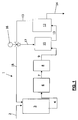
- FIG. 1 a plant 1 for the treatment of wastewater.
- the plant 1 can preferably be used for the treatment of waste water of the metalworking industry.
- the wastewater is fed to a biological degradation stage 3.
- the biodegradation step 3 is a conventional, known biodegradation step.
- the wastewater is supplied from the biological degradation stage 3 via a supply line 4 of a thermal disinfection 6.
- the thermal disinfection 6 will be closer to below FIG. 2 described.
- the wastewater is passed via a line 7 and a filter unit 8 by means of a supply line 9 in a storage tank 11 of a membrane system 12.
- the storage tank 11 and the membrane unit 12 are combined in a circuit 13.
- the filter unit 8, the storage tank 11 and the membrane unit 12 form an example of a filter system.
- Within the diaphragm circuit 11, 12, 13, the water is filtered out. Pollutants remain in a concentrate and are enriched in the reservoir 11.
- the treated water is discharged via a permeate effluent 14.
- the concentrate is split at a control valve 16.
- a main stream 17 is passed back into the feed tank 11, wherein a partial flow is conducted within a feed line 18 back to the biological degradation stage 3 for further biological treatment.
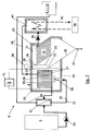
- the embodiment of the thermal disinfection 6 is in FIG. 2 shown.
- the thermal disinfection 6 has a precipitation chamber 19 and a separation chamber 21. Between the precipitation chamber 19 and the separation chamber 21 is on the one hand a septum 22 and on the other a weir 23 is arranged.
- the septum 22 extends from a broad side wall of the container, which is exemplified as a foot wall 24, to one of theticianwandung 24 opposite broad side wall of the container, which is exemplified as the top wall 26.
- an overflow opening 27 in the vicinity of the top wall 26 is arranged.
- the Weir 23 extends from the head wall 26 towards the foot wall 24 and ends shortly before a funnel 28, which will be explained below.
- the precipitation chamber 19 is separated from the separation chamber 21. Between the septum 22 and the weir 23, a drain 30 is formed.
- the wastewater coming from the biological decomposition stage 3 is first conducted via a feed pump 29 into a preheat exchanger 31. From the preheat exchanger 31, the water enters the precipitation chamber 19. At a feed line 32 to the precipitation chamber 19, a metering unit 33 is arranged for metering sodium bicarbonate. However, the dosing unit 33 can also be arranged such that it opens directly into the precipitation chamber 19 with a supply line.
- heat exchanger plates 34 are arranged.
- a plurality of heat exchanger plates 34 are combined to form a heat exchanger battery 36.
- the individual heat exchanger plates 34 are electrically separated from each other. This is achieved by e.g. Distribution lines 37 to the individual heat exchanger plates 34 are made of non-conductive plastic.
- the control of the thermal disinfection is via a thermostat 38.
- the thermostat 38 is arranged such that the temperature in the drain 30 can be controlled to control a primary energy source 46, which will be discussed below.
- the water is kept in motion by means of a submersible agitator 39.
- the submersible agitator 39 cooperates with baffles not shown in such a way that a uniform flow over the heat exchanger plates 34 is ensured.
- two of the heat exchanger plates 34 preferably the respective outer heat exchanger plates 34 are connected to a DC power source 41.
- the heat exchanger battery 36 may be configured such that all heat exchanger plates 34 are connected to the positive pole of the DC power source 41, wherein between the respective heat exchanger plates 34 suitable plates are arranged, which are connected to the negative pole of the DC power source 41st are connected.
- the heat exchanger plates 34 and the sheets are in this case electrically separated from each other.
- the water is passed through the drain 30 into the separation chamber 21 in which a slanting device 42 is arranged.
- a drain 43 is arranged, through which the water is passed into a high-temperature heat exchanger 44.
- a pump 48 is provided in the high-temperature heat exchanger 44.
- a heating element 45 is arranged, which is connected to a primary energy source 46.
- the thermal disinfection 6 has successively the preheat exchanger 31, the precipitation chamber 19, the deposition chamber 21 and the high-temperature heat exchanger 44.
- the sterilized water is passed after the high-temperature heat exchanger 44 on the primary side in the heat exchanger battery 36 to heat the precipitation chamber 19.
- the heat exchanger plates 34 are hollow for this purpose and connected by means of the distribution lines 37.
- the water is introduced into the preheat exchanger 31 to heat the incoming waste water in this.
- the precipitation chamber 19, the separation chamber 21 and / or the high-temperature heat exchanger 44 it is expedient for the preheat exchanger 31, the precipitation chamber 19, the separation chamber 21 and / or the high-temperature heat exchanger 44 to be thermally insulated with a thermal insulation material or the like. This further minimizes the primary energy input.
- the water is supplied to the further treatment in the filter system.
- the path of the sterilized water from the high-temperature heat exchanger 44, via the heat exchanger plates 34 and the preheat exchanger 31 to the filter system is in FIG. 2 exemplified by the line 49.
- the separated lime sludge from the oblique clarifier 42 is withdrawn at regular intervals on a bottom valve 47, which is arranged on the hopper 28.
Landscapes
- Chemical & Material Sciences (AREA)
- Engineering & Computer Science (AREA)
- Water Supply & Treatment (AREA)
- Chemical Kinetics & Catalysis (AREA)
- Life Sciences & Earth Sciences (AREA)
- Hydrology & Water Resources (AREA)
- Environmental & Geological Engineering (AREA)
- Organic Chemistry (AREA)
- Nanotechnology (AREA)
- Heat Treatment Of Water, Waste Water Or Sewage (AREA)
- Separation Using Semi-Permeable Membranes (AREA)
Description
- Die Erfindung betrifft ein Verfahren zur Aufbereitung von Abwasser, das einer biologischen Abbaustufe zugeführt wird, der eine Filteranlage nachgeschaltet ist. Die Erfindung betrifft aber auch eine Anlage zur Aufbereitung von Abwasser mit einer biologischen Abbaustufe sowie einer Filteranlage.
- Die
WO02/074698 - In der
EP 1 293 485 A1 ist ein Verfahren zur Aufbereitung von Industrieabwässern offenbart, bei dem das Abwasser mindestens eine chemisch/physikalische Flockung/Fällung , ein Filtersystem, eine biologische Abwasserreinigungsstufe sowie eine Nanofiltrationseinheit durchläuft. Dieses Verfahren hat sich in der Praxis bewährt. Allerdings kann es bei diesem Verfahren je nach Betriebszustand der Anlage zu einer starken Verkeimung des Abwassers hinter der biologischen Abwasserreinigungsstufe kommen, was zu einer Verblockung einer Membrananlage führen kann. - In der
DE 44 00 604 C1 wird ein Verfahren zum Betrieb einer Kleinstosmoseanlage offenbart, die in einem Umkehrosmosemodul aus zulaufendem Rohwasser ca. 10 - 50l/d Produktwasser in einem nahezu konstanten Produktwasserstrom herstellen kann. Der Produktwasserstrom wird auf ca. 70°C - 90°C erwärmt und anschließend wieder abgekühlt. Die Produktwassertemperatur wird solange auf einem keimtötenden Niveau gehalten, bis eine hinreichende Menge an Keimen im Produktwasser thermisch abgetötet wird. - Verfahren zur Abwasseraufbereitung in Kombination mit einer biologischen Abbaustufe sind bekannt. Diesen Verfahren ist das Grundprinzip gemeinsam, daß das Abwasser zunächst nach einer chemisch/physikalischen Vorbehandlung in eine biologische Abbaustufe eingeleitet wird. In der biologischen Abbaustufe werden im wesentlichen organische Kohlenwasserstoff-Verbindungen und Ammonium-Stickstoff-Verbindungen behandelt und biologisch abgebaut. Hinter der biologischen Abbaustufe wird das Abwasser in der Regel über geeignete Filtrationsverfahren einer Membrananlage zugeführt, in der dann mit Hilfe einer Ultra- oder Nanofiltration oder einer Umkehrosmose Restschadstoffe und Salze entfernt werden.
- Das Abwasser wird in einem Kreislauf mit hoher Geschwindigkeit über eine Membranoberfläche gespült. Lediglich das durch die Membrane durchdringende Wasser (Permeat) wird in diesem Kreislauf ersetzt. Hieraus folgert eine Aufkonzentration der Schadstoffe in diesen Kreislauf (Konzentrat). Zum weiteren Abbau aufkonzentrierter Kohlenwasserstoff- und Ammonium-Stickstoff-Verbindungen wird das Konzentrat nach Verlassen der Membrananlage zu einem Teil oder vollständig wieder der biologischen Abbaustufe zugeführt.
- Ein Hauptnachteil dieser Verfahren ist darin zu sehen, daß das Abwasser hinter der biologischen Abbaustufe mit Mikroorganismen belastet ist, deren Konzentration um so größer ist, je effektiver die biologische Abbaustufe arbeitet. Gerade diese mikrobiologische Belastung des Wassers führt aber zwangsläufig dazu, daß Bakterien und andere Mikroorganismen in die Membrananlage gespült werden und sich auf der Membranoberfläche und einem Spacer im Membranmodul ansiedeln und vermehren. Zudem werden die angesiedelten Bakterien im Membranmodul verfahrensbedingt ausreichend mit Sauerstoff und Substrat versorgt, so daß sich in kürzester Zeit eine eigene Biozönose bildet, die zu einer Verblockung des Membranmoduls führt.
- Diese Verblockung findet in zwei Stufen statt: Zunächst bildet sich ein Biofilm auf der Membranoberfläche aus, der ein Durchdringen des Wassers durch die Membrane verhindert. Danach bildet sich, bedingt durch den Wachstumszyklus der Bakterien, ein Überschußschlamm aus abgestorbenen Mikroorganismen, der sich im Spacer festsetzt und den Durchfluß durch die Membrane behindert.
- Bei Verfahren und Anlagen zur Aufbereitung von Abwasser als Kombination aus einer Membrananlage und einer biologischen Abbaustufe hat die mikrobiologische Aktivität des zu behandelnden Abwassers einen wesentlichen Einfluß auf die Leistungsfähigkeit, vor allem auf die Fluxrate der Membrananlage. Je größer die biologische Aktivität des Wassers, bedingt durch die biologische Abbaustufe ist, desto größer ist ein zu erwartendes Biofouling auf der Membranfläche, was zum Abfallen der Fluxrate durch die Membrane führt.
- Der vorliegenden Erfindung liegt die Aufgabe zugrunde, ein verbessertes Verfahren und eine verbesserte Anlage zur Aufbereitung von Abwässern zur Verfügung zu stellen, bei der eine Verblockung der Membrane vermieden wird.
- Erfindungsgemäß wird die Aufgabe zum einen durch ein Verfahren mit den Merkmalen des Anspruchs 1 und zu anderen mit einer Anlage mit den Merkmalen des Anspruchs 3 gelöst.
- Der Erfindung liegt die Erkenntnis zugrunde, daß zur Vermeidung einer Verblockung der Membrane eine Desinfektion zum Beispiel mit Biozid, mittels Wasserstoffsuperoxid, mit Chlor oder mittels einer elektrolytischen Desinfektion nicht geeignet ist, da z. B. das Biozid nicht lokal wirkt, sondern von dem Kreislaufwasser hinter der Membrananlage auch in die biologische Abbaustufe eingetragen und diese nachhaltig zerstören würde.
- Eine Desinfektion mit Wasserstoffsuperoxid als Desinfektionsmittel wirkt nur in Verbindung mit UV-Licht. Durch eine natürliche Trübung des Abwassers ist in der Regel aber davon auszugehen, daß die Eindringtiefe der UV-Strahlen für eine ausreichende Spaltung des Wasserstoffsuperoxids nicht gegeben ist. Darüber hinaus spricht noch ein weiterer Umstand gegen den Einsatz von Wasserstoffsuperoxid, der für alle oxidativ wirkenden Verfahren gilt. Die Wirkung von Wasserstoffsuperoxid beruht auf der Eigenschaft, daß aus einem Molekül durch die Bestrahlung mit UV-Licht ein Sauerstoffatom herausgebrochen wird, das als atomarer Sauerstoff einen Reaktionspartner sucht. Durch das sehr hohe Reaktionspotential reagiert der Sauerstoff mit den in der Zellstruktur eingelagerten DNS der Bakterien und verändert deren DNA, so daß die Bakterien entweder sofort absterben oder aber nicht mehr teilungsfähig sind.
- Durch die hohe Reaktivität des atomaren Sauerstoffs reagiert das Atom aber nicht nur mit der DNS der Bakterien, sondern auch mit anderen Partnern mit einem Oxidationspotential. Dies sind vor allem die organischen Inhaltsstoffe im Abwasser. Diese Reaktion ist bekannter Weise nicht selektiv. Die Desinfektion der Bakterien erfolgt proportional der Oxidation aller anderen Schadstoffe. Lediglich ein Bruchteil des eingesetzten Wasserstoffsuperoxids kommt der Bakteriendesinfektion tatsächlich zugute. Daraus folgt, daß dieses Verfahren sehr kostenintensiv ist, da je nach organischer Belastung des Abwassers unwirtschaftliche Mengen von Wasserstoffsuperoxid eingesetzt werden müssen.
- Eine Desinfektion mit Chlor führt zu denselben Nachteilen wie bei einer Desinfektion mit Biozid, was oben beschrieben wurde. Eine Depotwirkung des Chlors im Abwasser wird bei einem Kreislaufverfahren die biologische Abbaustufe nachhaltig zerstören.
- Ähnlich wie bei einer Desinfektion mit Wasserstoffsuperoxid wird bei einer elektrolytischen Desinfektion durch einen elektrolytischen Prozeß atomarer Sauerstoff durch die Spaltung von Wasser hergestellt. Die Wirkung auf Bakterien und Inhaltsstoffe ist ähnlich wie die zu der Desinfektion mit Wasserstoffsuperoxid, was oben beschrieben wurde. Der Einsatz einer elektrolytischen Desinfektion ist nur bei sehr kleinen Volumenströmen geeignet, da die Investitionskosten sehr hoch sind.
- Thermische Desinfektionsverfahren von Wasser und Abwasser beruhen auf dem Prinzip von Pasteur, wonach das Wasser auf eine erforderliche Temperatur erhitzt wird, um Bakterien, Keime und Viren nachhaltig abzutöten. Um den Energieaufwand für die Temperierung des Wassers zu minimieren, wird in der Regel eine Kaskade von Wärmetauschern eingesetzt, in denen die Energie des ablaufenden heißen Wassers an das ankommende kalte Wasser abgegeben wird. Hierbei treten Probleme auf, die in der vorteilhaften Anwendung des hier gezeigten Verfahrens berücksichtigt werden:
- Ausfallen von schwer löslichem Kalziumhydrogenkarbonat bei Temperaturen über 53 °C,
- Eliminieren von Kalziumsulfat um Gipsbildung zu minimieren,
- Minimieren des Primärenergieeinsatzes,
- Optimieren der Wärmetauscher-Oberflächen.
- Der Erfindung liegt weiterhin die Erkenntnis zugrunde, daß eine ausreichende Entkeimung für einen kontinuierlichen Betrieb mit 60 °C erreichbar ist, wobei allerdings in größeren Zeitabständen kurzfristig auch mit höheren Temperaturen (bis 80°C) entkeimt werden muß, um auch thermostabilere Bakterienstämme erfassen zu können.
- Um einer Membranverblockung vorzubeugen, ist es günstig im Sinne der Erfindung, wenn die thermische Desinfektion dem Biofilter direkt nachgeschaltet durchgeführt wird, um das Wasser thermisch zu entkeimen. Hierzu wird das Abwasser nach der biologischen Abbaustufe in die thermische Desinfektion geleitet. Aus der thermischen Desinfektion wird das Wasser über eine Filtereinheit in einen Vorlagebehälter der Membrananlage geleitet. Um möglichst viel Energie einzusparen ist es zweckmäßig, daß ein Volumenstrom aus der biologischen Abbaustufe minimiert wird, wobei der Volumenstrom ca. 120 % einer Permeatmenge hinter der Membrananlage betragen sollte. Im Membrankreislauf wird das Wasser ausgefiltert, wobei die Schadstoffe im Konzentrat bleiben und im Behälter angereichert werden. Das behandelte Wasser wird über einen Permeatablauf ausgeschleust. Das Konzentrat wird an einem Stellventil aufgeteilt. Ein Hauptstrom wird zurück in den Vorlagebehälter geleitet, wobei ein Teilstrom wieder zurück in die biologische Abbaustufe zur weiteren biologischen Behandlung geleitet wird.
- Das aus dem Biofilter kommende Abwasser wird zunächst über eine Förderpumpe in einen Vorwärmetauscher geführt. Hier wird das Abwasser in einem ersten Schritt auf eine Temperatur unterhalb der Ausfalltemperatur von Kalziumhydrogenkarbonat erwärmt. Diese liegt unterhalb von 52°C. Hinter dem Wärmetauscher gelangt das Wasser in eine Fällungskammer und anschließend in eine Abscheidekammer. Zumindest die Fällungskammer ist als geschlossener, druckloser Behälter ausgestaltet. Möglich ist, daß sowohl Fällungskammer als auch die Abscheidekammer in einem gemeinsamen Behälter, vorzugsweise einem geschlossenen, drucklosen Behälter angeordnet sind. In einer Zuleitung zur Fällungskammer wird über eine Dosiereinheit Natriumhydrogenkarbonat dosiert eingeführt, um Kalziumsulfatreste in der Fällungskammer zu eliminieren. Damit wird eine Gipsbildung in der thermischen Desinfektion minimiert. Selbstverständlich können auch andere geeignete Chemikalien eingesetzt werden, die geeignet sind, CaSO4x2H2O chemisch derart zu verändern, daß dieses nicht als Gips ausfallen kann.
- In der Fällungskammer ist eine Batterie aus Wärmetauscherplatten angeordnet. Die Größe der Wärmetauscherplatten ist so ausgelegt, daß das ankommende Wasser bei einem Regelbereich von 50 bis 60 °C in einem zweiten Schritt auf eine Temperatur von ca. 55 °C ± 1 °C erwärmt wird. Zur Verbesserung des Wärmeübergangs an der Oberfläche der Wärmetauscherplatten wird das Wasser über ein Tauchrührwerk in Bewegung gehalten. Zudem werden vorzugsweise die erste und die letzte Wärmetauscherplatte der Wärmetauscherplatten-Batterie an eine Gleichstromquelle angeschlossen und mit einer Gleichspannung von ca. 2 Volt beladen. Hierdurch wird erreicht, daß eine der Wärmetauscherplatte anodisch und eine dazu gegenüberliegende Wärmetauscherplatte kathodisch wirkt. Mittels dieses elektrolytischen Effektes wird erreicht, daß die positiv geladenen Ca-Ionen zur Kathode wandern. Um zu verhindern, daß sich auf der kathodischen Wärmetauscherplattenoberfläche Kalk ablagert, wird die Polung der Gleichstromquelle günstiger Weise in einstellbaren Zeiträumen getauscht. Dies hat den Vorteil, daß bereits auf der Oberfläche angelagerte Ca-lonen wieder abgestoßen werden.
- Das Wasser wird durch einen Ablauf in einen geeigneten Sedimentabscheider oder ein anderes geeignetes Filtersystem, bevorzugt einen Schrägklärer geleitet, der in der Abscheidekammer angeordnet ist. In dem Schrägklärer werden sedimentierbare Stoffe, insbesondere schwer lösliche Kalkflocken abgeschieden. An einem Ablauf wird das Wasser aus der Abscheidekammer in einen Hochtemperatur-Wärmetauscher geleitet. Hierzu kann auch eine Pumpe eingesetzt werden. In dem Hochtemperatur-Wärmetauscher wird das Wasser durch eine Primärenergiequelle in einem dritten Schritt auf 60 bis 80 °C, vorzugsweise bis auf 75°C erwärmt, um eine Vollentkeimung zu erreichen. Der Hochtemperatur-Wärmetauscher ist bevorzugt derart ausgelegt, daß eine ausreichende Verweilzeit zur Vollentkeimung gewährleistet ist.
- Das entkeimte Wasser wird nach dem Hochtemperatur-Wärmetauscher primärseitig in die Wärmetauscher-Batterie geleitet, um die Fällungskammer aufzuwärmen. Die Wärmetauscherplatten sind hierzu hohl ausgebildet und mittels Verteilleitungen verbunden. Nach Verlassen der Wärmetauscher-Batterie wird das Wasser in den Vorwärmetauscher eingeleitet, um das ankommende Abwasser in dem Vorwärmetauscher zu erwärmen. Dies ist günstig, da damit die Wärmeenergie aus dem Hochtemperatur-Wärmetauscher genutzt wird. Um möglichst geringe Wärmeenergie Verluste zu haben, ist es zweckmäßig, wenn der Vorwärmetauscher, die Fällungskammer, die Abscheidekammer und/oder der Hochtemperatur-Wärmetauscher mit einem Wärmedämmstoff oder dergleichen thermisch isoliert ist. Damit wird der Primäreintrag weiter minimiert. Nach Verlassen des Vorwärmetauschers wird das Wasser der weiteren Behandlung in der Filteranlage zugeführt.
- Günstig im Sinne der Erfindung ist, wenn die Steuerung der Primärenergiequelle über ein Thermostat erfolgt, welches den Sollwert für die Fällungskammer mißt. Durch die Steuerung der Primärenergiezufuhr mittels des Thermostats wird über die Entkeimungstemperatur im Hochtemperatur-Wärmetauscher die erforderliche Vorlauftemperatur in der Wärmetauscher-Batterie eingestellt.
- Um den elektrolytischen Effekt in der Wärmetauscher-Batterie zu erreichen, wird diese zweckmäßigerweise derart gestaltet, daß die einzelnen Wärmetauscherplatten elektrisch voneinander getrennt sind. Dies wird bevorzugt dadurch erreicht, daß die Verteilleitungen zu den einzelnen Platten aus nicht-leitendem Kunststoff bestehen.
- In einer alternativen Ausgestaltung wird jede Wärmetauscherplatte an den Pluspol der Gleichstromquelle angeschlossen, wobei zwischen jeder Wärmetauscherplatte eine Blechtafel, vorzugsweise eine Edelstahl-Blechtafel angeordnet ist, die an den Minuspol der Gleichstromquelle angeschlossen ist. Hiermit wird vorteilhafter Weise erreicht, daß die Wärmetauscher-Platten anodisch wirken und die dazwischen angeordneten Blechtafeln kathodisch wirken. Die positiv geladenen Ca-lonen werden nun bestrebt sein, sich an der Kathode anzulagern. Damit wird besonders vorteilhaft verhindert, daß sich Kalkablagerungen an den Wärmetauscherplatten bilden.
- Der abgeschiedene Kalkschlamm aus dem Schrägklärer wird in regelmäßigen Abständen an einem Bodenventil eines Trichters, welcher der Abscheidekammer zugeordnet ist abgezogen.
- Mit dem Erfindungsgemäßen Verfahren und der erfindungsgemäßen Anlage zur Aufbereitung von Abwässern wird biologisch aktives Abwasser aus dem Ablauf der biologischen Abbaustufe desinfiziert, bevor es in den Membrankreislauf geleitet wird. Damit wird ein biologisches Wachstum zumindest vermindert oder sogar vollständig unterbunden.
- Weiter kann der Energieeintrag bei einer Entkeimungstemperatur von 60 °C auf einen Energieverbrauch von ca. 8,9 kWh/m3 Wasser begrenzt werden. Höchst vorteilhaft ist, daß keine zusätzliche Primärenergie dadurch verbraucht wird, daß neben der Entkeimung auch andere organische Verbindungen im Wasser abgebaut werden.
- Ein zusätzlich vorteilhafter Aspekt der Erfindung ist in der Teilentkalkung des Wassers zu sehen, wodurch die Bedingungen für die Membranen verbessert werden. Mittels der Abscheidung des Kalziumhydrogenkarbonats vor der Membrane kann ein durchschnittliche Flux um mehr als 15 % gesteigert werden.
- Weitere vorteilhafte Ausgestaltungen der Erfindung sind in den Unteransprüchen und in der folgenden Figurenbeschreibung offenbart.
- Es zeigen:
- Figur 1
- eine schematische Darstellung einer Abwasserbehandlungsanlage,
- Figur 2
- eine thermischen Desinfektionsanlage im Querschnitt.
- In den einzelnen Figuren sind gleiche Teile stets mit denselben Bezugszeichen versehen, so daß sie in der Regel auch nur einmal beschrieben werden.
-
Figur 1 eine Anlage 1 zur Aufbereitung von Abwässern. Die Anlage 1 kann bevorzugt zur Behandlung von Abwässern der metallverarbeitenden Industrie verwendet werden. Über eine Zuleitung 2 wird das Abwasser einer biologischen Abbaustufe 3 zugeführt wird. Die biologische Abbaustufe 3 ist eine herkömmliche, bekannte biologische Abbaustufe. Das Abwasser wird aus der biologischen Abbaustufe 3 über eine Zuleitung 4 einer thermischen Desinfektion 6 zugeführt. Die thermische Desinfektion 6 wird nachfolgend näher zuFigur 2 beschrieben. - Aus der thermischen Desinfektion 6 wird das Abwasser über eine Leitung 7 und einer Filtereinheit 8 mittels einer Zuleitung 9 in einen Vorlagebehälter 11 einer Membrananlage 12 geführt. Der Vorlagebehälter 11 und die Membrananlage 12 sind in einem Kreislauf 13 zusammengeschlossen. Die Filtereinheit 8, der Vorlagebehälter 11 und die Membrananlage 12 bilden beispielhaft eine Filteranlage. Innerhalb des Membrankreislaufs 11, 12, 13 wird das Wasser ausgefiltert. Schadstoffe bleiben in einem Konzentrat und werden in dem Vorlagebehälter 11 angereichert. Das behandelte Wasser wird über einen Permeatablauf 14 ausgeschleust. Das Konzentrat wird an einem Stellventil 16 aufgeteilt. Ein Hauptstrom 17 wird zurück in den Vorlagebehälter 11 geleitet, wobei ein Teilstrom innerhalb einer Zuleitung 18 zurück in die biologische Abbaustufe 3 zur weiteren biologischen Behandlung geleitet wird.
- Die Ausgestaltung der thermischen Desinfektion 6 ist in
Figur 2 dargestellt. Die thermische Desinfektion 6 weist eine Fällungskammer 19 und eine Abscheidekammer 21 auf. Zwischen der Fällungskammer 19 und der Abscheidekammer 21 ist zum einen eine Scheidewand 22 und zum anderen ein Wehr 23 angeordnet. Die Scheidewand 22 erstreckt sich von einer Breitseitenwandung des Behälters, die beispielhaft als Fußwandung 24 bezeichnet wird, zu einer der Fußwandung 24 gegenüberliegenden Breitseitenwandung des Behälters, die beispielhaft als Kopfwandung 26 bezeichnet wird. In der Scheidewand 22 ist eine Überströmöffnung 27 in der Nähe der Kopfwandung 26 angeordnet. Das Wehr 23 erstreckt sich von der Kopfwandung 26 in Richtung zur Fußwandung 24 und endet kurz vor einem Trichter 28, der weiter unten erläutert wird. Somit ist die Fällungskammer 19 von der Abscheidekammer 21 getrennt. Zwischen der Scheidewand 22 und dem Wehr 23 ist ein Ablauf 30 gebildet. - Das aus der biologischen Abbaustufe 3 kommende Abwasser wird zunächst über eine Förderpumpe 29 in einen Vorwärmetauscher 31 geführt. Von dem Vorwärmetauscher 31 gelangt das Wasser in die Fällungskammer 19. An einer Zuleitung 32 zur Fällungskammer 19 ist eine Dosiereinheit 33 zur Dosierung von Natriumhydrogenkarbonat angeordnet. Die Dosiereinheit 33 kann aber auch derart angeordnet sein, daß sie mit einer Zuleitung direkt in der Fällungskammer 19 mündet.
- In der Fällungskammer 19 sind Wärmetauscherplatten 34 angeordnet. Vorzugsweise sind mehrere Wärmetauscherplatten 34 zu einer Wärmetauscher-Batterie 36 zusammengefaßt. Die einzelnen Wärmtauscherplatten 34 sind elektrisch voneinander getrennt. Dies wird erreicht, indem z.B. Verteilleitungen 37 zu den einzelnen Wärmtauscherplatten 34 aus nicht-leitendem Kunststoff bestehen. Die Steuerung der thermischen Desinfektion erfolgt über ein Thermostat 38. Das Thermostat 38 ist derart angeordnet, daß die Temperatur in dem Ablauf 30 kontrolliert werden kann, um eine Primärenergiequelle 46 zu steuern, auf die weiter unten eingegangen wird.
- Zur Verbesserung des Wärmeübergangs an den Oberflächen der Wärmetauscherplatten 34 wird das Wasser über ein Tauchrührwerk 39 in Bewegung gehalten. Das Tauchrührwerk 39 wirkt mit nicht dargestellten Leitblechen derart zusammen, daß eine gleichmäßige Überströmung der Wärmetauscherplatten 34 gewährleistet ist. Zudem werden zwei der Wärmtauscherplatten 34, vorzugsweise die jeweils äußeren Wärmetauscherplatten 34 an eine Gleichstromquelle 41 angeschlossen. Die Wärmetauscherbatterie 36 kann derart ausgestaltet sein, daß alle Wärmetauscherplatten 34 an den Pluspol der Gleichstromquelle 41 angeschlossen werden, wobei zwischen den jeweiligen Wärmetauscherplatten 34 geeignete Bleche angeordnet sind, die an den Minuspol der Gleichstromquelle 41 angeschlossen sind. Die Wärmetauscherplatten 34 und die Bleche sind hierbei elektrisch voneinander getrennt.
- Das Wasser wird durch den Ablauf 30 in die Abscheidekammer 21, in der ein Schrägklärer 42 angeordnet ist geleitet.
- In der Abscheidekammer 21 ist ein Ablauf 43 angeordnet, durch den das Wasser in einen Hochtemperatur-Wärmetauscher 44 geleitet wird. Hierzu ist eine Pumpe 48 vorgesehen. In dem Hochtemperatur-Wärmetauscher 44 ist ein Heizelement 45 angeordnet, daß mit einer Primärenergiequelle 46 verbunden ist.
- Die thermische Desinfektion 6 weist aufeinanderfolgend den Vorwärmetauscher 31, die Fällungskammer 19, die Abscheidekammer 21 und den Hochtemperatur-Wärmetauscher 44 auf.
- Das entkeimte Wasser wird nach dem Hochtemperatur-Wärmetauscher 44 primärseitig in die Wärmetauscher-Batterie 36 geleitet, um die Fällungskammer 19 aufzuwärmen. Die Wärmetauscherplatten 34 sind hierzu hohl ausgebildet und mittels der Verteilleitungen 37 verbunden. Nach Verlassen der Wärmetauscher-Batterie 36 wird das Wasser in den Vorwärmetauscher 31 eingeleitet, um das ankommende Abwasser in diesem zu erwärmen. Um möglichst geringe Wärmeenergie Verluste zu haben, ist es zweckmäßig, wenn der Vorwärmetauscher 31, die Fällungskammer 19, die Abscheidekammer 21 und/oder der Hochtemperatur-Wärmetauscher 44 mit einem Wärmedämmstoff oder dergleichen thermisch isoliert ist. Damit wird der Primärenergieeintrag weiter minimiert. Nach Verlassen des Vorwärmetauschers 31 wird das Wasser der weiteren Behandlung in der Filteranlage zugeführt. Der Weg des entkeimten Wassers von dem Hochtemperatur-Wärmetauscher 44, über die Wärmetauscherplatten 34 und den Vorwärmetauscher 31 zur Filteranlage ist in
Figur 2 beispielhaft mittels der Leitung 49 dargestellt. - Der abgeschiedene Kalkschlamm aus dem Schrägklärer 42 wird in regelmäßigen Abständen an einem Bodenventil 47, das an dem Trichter 28 angeordnet ist abgezogen.
- Mit der erfindungsgemäßen Anlage und dem erfindungsgemäßen Verfahren zur Aufbereitung von Industrieabwässern wird erreicht, daß eine Verblockung der Membrane verhindert wird, indem das Abwasser thermisch desinfiziert wird um Biofouling, das durch Keimbildung in der biologischen Abbaustufe verursacht wird, in der nachgeschalteten Membrananlage zu vermindern.
Claims (5)
- Verfahren zur Aufbereitung von Abwasser, das einer biologischen Abbaustufe (3) zugeführt wird, der eine Filteranlage nachgeschaltet ist,
gekennzeichnet durch
eine thermische Desinfektion (6), welche der biologischen Abbaustufe (3) nachgeschaltet und der Filteranlage vorgeschaltet ist, wobei in der thermischen Desinfektion (6) das Abwasser entkeimt wird, wobei das Abwasser
in einem ersten Schritt in einem Vorwärmetauscher (31) auf eine Temperatur unterhalb der Ausfalltemperatur von Kalziumhydrogenkarbonat erwärmt wird,
in einem zweiten Schritt in einer Fällungskammer (19) bei einem Regelbereich von 50°C bis 60°C auf eine Temperatur von 55°C ± 1°C erwärmt wird, und
in einem dritten Schritt in einem Wärmetauscher (44) auf eine Temperatur von 60°C bis 80°C erwärmt wird - Verfahren nach Anspruch 1,
dadurch gekennzeichnet, daß
nach dem dritten Schritt entkeimtes Wasser von dem Wärmetauscher (44) primärseitig in Wärmetauscherplatten (34) geleitet wird, die in der Fällungskammer (19) angeordnet sind, um die Fällungskammer (19) aufzuwärmen und anschließend in den Vorwärmetauscher (31) geleitet wird, um das ankommende Abwasser in diesem zu erwärmen, wobei das entkeimte Wasser nach Verlassen des Vorwärmetauschers (31) zur weiteren Behandlung der Filteranlage zugeführt wird. - Anlage zur Aufbereitung von Abwasser mit einer biologischen Abbaustufe (3) und einer Filteranlage insbesondere zur Durchführung des Verfahrens nach den vorhergehenden Ansprüchen,
gekennzeichnet durch
eine thermische Desinfektion (6), welche der biologischen Abbaustufe (3) nachgeschaltet und der Filteranlage vorgeschaltet ist, wobei die thermische Desinfektion (6) aufeinander folgend einen Vorwärmetauscher (31), eine Fällungskammer (19), eine Abscheidekammer (21) und einen Wärmetauscher (44) aufweist, wobei das Abwasser in mehreren Schritten und zwar in einem ersten Schritt in dem Vorwärmetauscher (31) auf eine Temperatur unterhalb der Ausfalltemperatur von Kalziumhydrogenkarbonat, in einem zweiten Schritt in der Fällungskammer (19) bei einem Regelbereich von 50°C bis 60°C auf eine Temperatur von 55°C ± 1 °C und in einem dritten Schritt in dem Wärmetauscher (44) auf eine Temperatur von 60°C bis 80°C erwärmt wird, so dass das Abwasser in der thermischen Desinfektion (6) entkeimbar ist. - Anlage nach Anspruch 3,
dadurch gekennzeichnet, daß
die thermische Desinfektion (6) in ihrer Fällungskammer (19) mehrere Wärmetauscherplatten (34) aufweist, die vorzugsweise zu einer Wärmetauscherplatten-Batterie (36) zusammengefaßt sind. - Anlage nach Anspruch 3 oder 4,
dadurch gekennzeichnet, daß
der thermischen Desinfektion (6) eine an in ihrer Fällungskammer (19) angeordneten Wärmetauscherplatten (34) angeschlossene Gleichstromquelle (41) zugeordnet ist.
Priority Applications (1)
| Application Number | Priority Date | Filing Date | Title |
|---|---|---|---|
| EP20030104877 EP1547977B1 (de) | 2003-12-22 | 2003-12-22 | Verfahren zur Aufbereitung von Abwasser |
Applications Claiming Priority (1)
| Application Number | Priority Date | Filing Date | Title |
|---|---|---|---|
| EP20030104877 EP1547977B1 (de) | 2003-12-22 | 2003-12-22 | Verfahren zur Aufbereitung von Abwasser |
Publications (2)
| Publication Number | Publication Date |
|---|---|
| EP1547977A1 EP1547977A1 (de) | 2005-06-29 |
| EP1547977B1 true EP1547977B1 (de) | 2011-11-23 |
Family
ID=34530797
Family Applications (1)
| Application Number | Title | Priority Date | Filing Date |
|---|---|---|---|
| EP20030104877 Expired - Lifetime EP1547977B1 (de) | 2003-12-22 | 2003-12-22 | Verfahren zur Aufbereitung von Abwasser |
Country Status (1)
| Country | Link |
|---|---|
| EP (1) | EP1547977B1 (de) |
Cited By (1)
| Publication number | Priority date | Publication date | Assignee | Title |
|---|---|---|---|---|
| US10927014B1 (en) * | 2018-06-06 | 2021-02-23 | Raymond C. Sherry | Waste water treatment to reduce BOD/COD |
Families Citing this family (2)
| Publication number | Priority date | Publication date | Assignee | Title |
|---|---|---|---|---|
| DE102006015538A1 (de) * | 2006-03-31 | 2007-10-11 | H. C. Starck Gmbh & Co. Kg | Vorrichtung und Verfahren zur Herstellung von Verbindungen durch Fällung |
| CN118359250A (zh) * | 2024-05-22 | 2024-07-19 | 贵州金泽新能源科技有限公司 | 一种灭菌装置、生产回用水循环利用系统及灭菌方法 |
Family Cites Families (5)
| Publication number | Priority date | Publication date | Assignee | Title |
|---|---|---|---|---|
| US3850801A (en) * | 1973-06-07 | 1974-11-26 | Mcquay Perfex Inc | Waste water purification system |
| WO2002074698A1 (en) * | 2001-03-20 | 2002-09-26 | Water Minerals Limited | Removal of sulphates from a feedstock |
| DE10156289A1 (de) * | 2001-11-19 | 2003-06-18 | Nocado Armaturenfab Gmbh & Co | Vorrichtung und Verfahren zur Reinwasseraufbereitung |
| FR2833938B1 (fr) * | 2001-12-20 | 2004-03-12 | S C R D Esteve Patrick | Procede de traitement d'effluents charges en graisses et unite de traitement mettant en oeuvre le procede |
| DE50206295D1 (de) * | 2002-01-31 | 2006-05-18 | Ford Global Tech Inc | Verfahren zur Aufbereitung von Industrieabwässern |
-
2003
- 2003-12-22 EP EP20030104877 patent/EP1547977B1/de not_active Expired - Lifetime
Cited By (2)
| Publication number | Priority date | Publication date | Assignee | Title |
|---|---|---|---|---|
| US10927014B1 (en) * | 2018-06-06 | 2021-02-23 | Raymond C. Sherry | Waste water treatment to reduce BOD/COD |
| US11618691B1 (en) | 2018-06-06 | 2023-04-04 | Raymond C. Sherry | Waste water treatment to reduce BOD/COD |
Also Published As
| Publication number | Publication date |
|---|---|
| EP1547977A1 (de) | 2005-06-29 |
Similar Documents
| Publication | Publication Date | Title |
|---|---|---|
| EP0779829B1 (de) | Verfahren und vorrichtung zum entsalzen von meerwasser | |
| Valderrama et al. | Winery wastewater treatment for water reuse purpose: Conventional activated sludge versus membrane bioreactor (MBR): A comparative case study | |
| Tafti et al. | Optimized coupling of an intermittent DC electric field with a membrane bioreactor for enhanced effluent quality and hindered membrane fouling | |
| Ma et al. | Effects of dissolved organic matter size fractions on trihalomethanes formation in MBR effluents during chlorine disinfection | |
| CN107055713A (zh) | 一种基于单价阳离子选择性电渗析的高硬度含盐水浓缩方法 | |
| Pervov | Precipitation of calcium carbonate in reverse osmosis retentate flow by means of seeded techniques—A tool to increase recovery | |
| US12012347B2 (en) | Cooling pond water treatment system | |
| EP1293485B1 (de) | Verfahren zur Aufbereitung von Industrieabwässern | |
| DE102008004663B4 (de) | Verfahren zur elektrochemischen Hygienisierung und Keimminderung von biologisch gereinigtem Abwasser, insbesondere häuslichem Abwasser, und von Abwasserteilströmen und Vorrichtung dazu | |
| Wisniewski et al. | Use of a membrane bioreactor for denitrification of brine from an electrodialysis process | |
| DE102009026375A1 (de) | Ankopplungs- und Umschalteinheit für Leitungen zum Transport von Fluiden | |
| CN108046482A (zh) | 一种高盐分高硬度难降解有机浓缩废水处理方法及系统 | |
| DE102015006706A1 (de) | Kontinuierliches Verfahren zur Entfernung von Mikro-Verunreinigungen aus biologisch geklärtem, kommunalen Abwasser | |
| EP2078174B1 (de) | Wasseraufbereitungssystem | |
| EP1547977B1 (de) | Verfahren zur Aufbereitung von Abwasser | |
| DE10247686B3 (de) | Reaktor zum Entkalken und gleichzeitigem Entfernen von Schadstoffen | |
| EP0990622A2 (de) | Verfahren und Vorrichtung zur biologischen Reinigung von Abwasser | |
| AT519319B1 (de) | Aufbereitung von Abwasser zu Trinkwasser mittels Ozon | |
| DE102009026377A1 (de) | Anlage zur Desinfektion und Sanitisierung | |
| WO2017157388A1 (de) | Modulares verfahren und abwasserbehandlungsanordnung zur effizienten reinigung von abwasser | |
| EP0971858B1 (de) | Verfahren zum aufbereiten von abwasser, insbesondere aus mälzereien und brauereien | |
| EP2464447A1 (de) | Vorrichtung zum eintrag von gas in flüssigkeiten | |
| Miquel et al. | A newly developed process for nitrate removal from drinking water | |
| BR112021000632A2 (pt) | Anólito como um aditivo para tratamento de água residual | |
| El-Ghzizel et al. | Brine recycling impact on nitrate removal and electrochemical disinfection performances: a case study of Sidi Taibi desalination plant |
Legal Events
| Date | Code | Title | Description |
|---|---|---|---|
| PUAI | Public reference made under article 153(3) epc to a published international application that has entered the european phase |
Free format text: ORIGINAL CODE: 0009012 |
|
| AK | Designated contracting states |
Kind code of ref document: A1 Designated state(s): AT BE BG CH CY CZ DE DK EE ES FI FR GB GR HU IE IT LI LU MC NL PT RO SE SI SK TR |
|
| AX | Request for extension of the european patent |
Extension state: AL LT LV MK |
|
| 17P | Request for examination filed |
Effective date: 20051229 |
|
| AKX | Designation fees paid |
Designated state(s): DE FR GB |
|
| 17Q | First examination report despatched |
Effective date: 20090325 |
|
| GRAP | Despatch of communication of intention to grant a patent |
Free format text: ORIGINAL CODE: EPIDOSNIGR1 |
|
| GRAS | Grant fee paid |
Free format text: ORIGINAL CODE: EPIDOSNIGR3 |
|
| GRAA | (expected) grant |
Free format text: ORIGINAL CODE: 0009210 |
|
| AK | Designated contracting states |
Kind code of ref document: B1 Designated state(s): DE FR GB |
|
| REG | Reference to a national code |
Ref country code: GB Ref legal event code: FG4D Free format text: NOT ENGLISH |
|
| RAP2 | Party data changed (patent owner data changed or rights of a patent transferred) |
Owner name: FORD GLOBAL TECHNOLOGIES, LLC, A SUBSIDARY OF FORD |
|
| REG | Reference to a national code |
Ref country code: DE Ref legal event code: R096 Ref document number: 50314081 Country of ref document: DE Effective date: 20120202 |
|
| PLBE | No opposition filed within time limit |
Free format text: ORIGINAL CODE: 0009261 |
|
| STAA | Information on the status of an ep patent application or granted ep patent |
Free format text: STATUS: NO OPPOSITION FILED WITHIN TIME LIMIT |
|
| 26N | No opposition filed |
Effective date: 20120824 |
|
| REG | Reference to a national code |
Ref country code: DE Ref legal event code: R097 Ref document number: 50314081 Country of ref document: DE Effective date: 20120824 |
|
| REG | Reference to a national code |
Ref country code: FR Ref legal event code: PLFP Year of fee payment: 13 |
|
| REG | Reference to a national code |
Ref country code: FR Ref legal event code: PLFP Year of fee payment: 14 |
|
| REG | Reference to a national code |
Ref country code: FR Ref legal event code: PLFP Year of fee payment: 15 |
|
| PGFP | Annual fee paid to national office [announced via postgrant information from national office to epo] |
Ref country code: FR Payment date: 20171120 Year of fee payment: 15 |
|
| PGFP | Annual fee paid to national office [announced via postgrant information from national office to epo] |
Ref country code: GB Payment date: 20171128 Year of fee payment: 15 |
|
| PGFP | Annual fee paid to national office [announced via postgrant information from national office to epo] |
Ref country code: DE Payment date: 20171221 Year of fee payment: 15 |
|
| REG | Reference to a national code |
Ref country code: DE Ref legal event code: R119 Ref document number: 50314081 Country of ref document: DE |
|
| GBPC | Gb: european patent ceased through non-payment of renewal fee |
Effective date: 20181222 |
|
| PG25 | Lapsed in a contracting state [announced via postgrant information from national office to epo] |
Ref country code: DE Free format text: LAPSE BECAUSE OF NON-PAYMENT OF DUE FEES Effective date: 20190702 Ref country code: FR Free format text: LAPSE BECAUSE OF NON-PAYMENT OF DUE FEES Effective date: 20181231 |
|
| PG25 | Lapsed in a contracting state [announced via postgrant information from national office to epo] |
Ref country code: GB Free format text: LAPSE BECAUSE OF NON-PAYMENT OF DUE FEES Effective date: 20181222 |