EP1547881A2 - Hebel-Welle-Vorrichtung, Verfahren zur Herstellung einer Hebel-Welle-Vorrichtung und Scheibenwischanlage mit einer Hebel-Welle-Vorrichtung - Google Patents
Hebel-Welle-Vorrichtung, Verfahren zur Herstellung einer Hebel-Welle-Vorrichtung und Scheibenwischanlage mit einer Hebel-Welle-Vorrichtung Download PDFInfo
- Publication number
- EP1547881A2 EP1547881A2 EP04026424A EP04026424A EP1547881A2 EP 1547881 A2 EP1547881 A2 EP 1547881A2 EP 04026424 A EP04026424 A EP 04026424A EP 04026424 A EP04026424 A EP 04026424A EP 1547881 A2 EP1547881 A2 EP 1547881A2
- Authority
- EP
- European Patent Office
- Prior art keywords
- shaft
- lever
- wiper system
- windscreen wiper
- shaft device
- Prior art date
- Legal status (The legal status is an assumption and is not a legal conclusion. Google has not performed a legal analysis and makes no representation as to the accuracy of the status listed.)
- Granted
Links
- 238000004519 manufacturing process Methods 0.000 title claims abstract description 10
- 239000000463 material Substances 0.000 claims abstract description 21
- 238000000034 method Methods 0.000 abstract description 10
- 230000005540 biological transmission Effects 0.000 description 7
- 230000002349 favourable effect Effects 0.000 description 3
- 210000000078 claw Anatomy 0.000 description 2
- QNRATNLHPGXHMA-XZHTYLCXSA-N (r)-(6-ethoxyquinolin-4-yl)-[(2s,4s,5r)-5-ethyl-1-azabicyclo[2.2.2]octan-2-yl]methanol;hydrochloride Chemical compound Cl.C([C@H]([C@H](C1)CC)C2)CN1[C@@H]2[C@H](O)C1=CC=NC2=CC=C(OCC)C=C21 QNRATNLHPGXHMA-XZHTYLCXSA-N 0.000 description 1
- 241000309551 Arthraxon hispidus Species 0.000 description 1
- 229910003460 diamond Inorganic materials 0.000 description 1
- 239000010432 diamond Substances 0.000 description 1
- 230000000694 effects Effects 0.000 description 1
Images


Classifications
-
- B—PERFORMING OPERATIONS; TRANSPORTING
- B60—VEHICLES IN GENERAL
- B60S—SERVICING, CLEANING, REPAIRING, SUPPORTING, LIFTING, OR MANOEUVRING OF VEHICLES, NOT OTHERWISE PROVIDED FOR
- B60S1/00—Cleaning of vehicles
- B60S1/02—Cleaning windscreens, windows or optical devices
- B60S1/04—Wipers or the like, e.g. scrapers
- B60S1/06—Wipers or the like, e.g. scrapers characterised by the drive
- B60S1/16—Means for transmitting drive
- B60S1/18—Means for transmitting drive mechanically
- B60S1/24—Means for transmitting drive mechanically by rotary cranks
-
- F—MECHANICAL ENGINEERING; LIGHTING; HEATING; WEAPONS; BLASTING
- F16—ENGINEERING ELEMENTS AND UNITS; GENERAL MEASURES FOR PRODUCING AND MAINTAINING EFFECTIVE FUNCTIONING OF MACHINES OR INSTALLATIONS; THERMAL INSULATION IN GENERAL
- F16D—COUPLINGS FOR TRANSMITTING ROTATION; CLUTCHES; BRAKES
- F16D1/00—Couplings for rigidly connecting two coaxial shafts or other movable machine elements
- F16D1/06—Couplings for rigidly connecting two coaxial shafts or other movable machine elements for attachment of a member on a shaft or on a shaft-end
- F16D1/064—Couplings for rigidly connecting two coaxial shafts or other movable machine elements for attachment of a member on a shaft or on a shaft-end non-disconnectable
- F16D1/072—Couplings for rigidly connecting two coaxial shafts or other movable machine elements for attachment of a member on a shaft or on a shaft-end non-disconnectable involving plastic deformation
Definitions
- the invention relates to a lever-shaft device, a Method for producing a lever-shaft device and a Windscreen wiper system with a lever-shaft device after the Preambles of the independent claims.
- a lever-shaft device especially for windscreen wiper systems can be and with the torque from a drive unit can transfer to a lever.
- a frictional connection can be made by the lever with a Screw is tightened and produces a clamp connection.
- One Positive locking can be achieved by a shaft with conical Knurled knurled with an axially mounted lever with a nut becomes.
- the lever can be riveted to the shaft.
- a shaft-crank connection which is formed by a press connection.
- a Transmission output shaft of a windscreen wiper device rotatably with connected to a crank.
- the transmission output shaft is necessarily axial heavily loaded. The joining must be done before the drive motor is closed.
- lever-shaft device in particular for a windscreen wiper system, proposed in which a shaft in a connection area between a lever and the shaft at least partially surrounded by plastically deformed lever material of the lever is.
- This allows a positive connection or frictional engagement between Lever and shaft made and sufficient torque be transferred from the shaft to the lever.
- the joining process can at the Shaft of a finished closed engine are made. This facilitates production and saves costs in production.
- the lever can be attached at any angle to the shaft become. A connection between shaft and lever can already with least or even with disappearing shaft overhang reliable will be realized. This allows a small amount of Achieve lever shaft device.
- a selectable shaft overhang feasible which is favorable for is a torque transmission from the shaft to the lever. in the Unlike screw connections can both mounting hardware as well as production steps in production can be saved.
- the lever on a hole in which the shaft engages can a suitable geometric coordination between a contour of Shaft and a contour of the bore can be made.
- the hole has a deviating from a circle Contour, in particular with changes in curvature and / or edges on.
- a forked lever is conceivable that the shaft only partially encompassed.
- the contour of the hole or where appropriate the fork may in particular rhombic, teardrop-shaped, pear-shaped, be double-bulbous, also edged contours are conceivable.
- An advantageous frictional connection or positive connection can be achieved if the shaft at least in the connection area an angular contour having.
- the contour of the shaft and the contour of the lever will be suitably matched, with advantageous Combinations of contours and / or diameters and / or material combinations to achieve an optimized form fit or frictional engagement can be selected.
- the safety of the connection between shaft and lever can be improved when the shaft starting from the end face a Paragraph has in the connection area on which the lever is placed is.
- the lever is easy to position; the assembly is simplified. It is favorable, if the contour of the wave at the of the Lever on the shoulder covered area is edged, bringing an advantageous adhesion between the shaft and lever can be achieved can.
- a groove may be provided in the connection area of the shaft be, having the plastically deformed lever material.
- the groove is designed as a circumferential annular groove.
- a groove bottom expediently has an edged contour to a favorable To allow traction between lever and shaft.
- the Lever shaft device when the lever material a has lower elastic yield strength than a shaft material, from which the shaft is formed at least in the connection area.
- the difference is so large that the preferred Cold forming joining process essentially limited to the lever remains and an influence on the wave is omitted.
- the wave can vary in different areas Have yield strengths and different Materials may be formed or formed of a material.
- the elastic yield strength of the shaft material is greater than the elastic yield point of the lever material.
- a wave is at one Connected end face with a lever arranged at an angle to the shaft, it being suggested that for fixing the lever on the shaft of the lever in a connection area with the shaft at least partially plastically deformed by cold forming. Since the lever is deformed with forces acting radially to the shaft, An effect of axial forces on the shaft can be avoided. This allows a joining process to a finished motor.
- the lever shaft device in a connection area between a shaft and a lever has a plastically deformed lever material.
- the Lever is preferably designed as a crank plate, which advantageously just be executed. A cranking of the crank plate can be omitted.
- the lever-shaft device is characterized by a low altitude.
- Fig. 1 a shows a plan view of a not explained in detail usual Windscreen wiper drive 30 with an undeformed lever 14 on a shaft 12 before a joining operation to form a lever-shaft device 10 (Fig. 1b).
- the lever 14 is a plane crank plate for actuating a windscreen wiper, not shown or wiper linkage formed.
- On a side facing away from the shaft 12 Flat side of the lever 14 is a conventional joint head 32nd intended.
- a conventional Wischgestlinde be attached, which wiper blades drives, the wipe over a window of a vehicle.
- the shaft 12 engages a bore 20 of the lever 14 a.
- Fig. 1 b shows a detail of a lever-shaft device 10 after the Joining process with a shaft overhang.
- a wave 12 interspersed in a bore 20 of an angle projecting lever 14 and projects a shaft end with its end face 24 beyond the lever 14 also.
- a connection region 18 it can be seen that the lever 14 by the cold forming of the lever 14 in the connection area 18 is tapered towards an end piece 34.
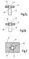
- Fig. 2 a shows a longitudinal section through a shaft 12 with a shoulder 26 at a shaft end, wherein a lever 14 on the shoulder 26 is seated. With a tapered shaft end, the shaft 12 engages a bore 20 of the lever 14 a.
- the end face 24 is substantially flush with a remote from the shaft 12 Flat side of the lever 14 from.
- 2 b shows a variant, in which at a shaft end of a shaft 12 has a circumferential groove 28 is provided.
- the shaft 12 protrudes into a bore 20 of a lever 14 and has a projection, so that the end face 24th not flush with a side facing away from the shaft 12 flat side of the Levers 14 closes, but this towers over.
- Fig. 3 shows schematically a cross section through a connecting region 18 of a lever 14 with a shaft 12 of one Circle deviating contours before a joining process.
- the one by one Circle deviating contour 22 of a bore 20 has diamond shape on, while the shaft 12 has an edged contour.
- To the joining process is at least partially in a connection area 18 between shaft 12 and lever 14 plastically deformed Leverage in frictional or positive Contact with the shaft 12.
- Fig. 4 a shows a plan view of one in a preferred trapezoidal Forming tool arranged lever-shaft device 10th
- a shaft end of the shaft 12 is of two trapezoidal punches 40, 42 applied with axial force and deforms plastically. there the shaft 12 is at least partially plastically deformed Surrounded lever material and a frictional engagement or positive engagement educated.
- Fig. 4 b shows and a view obliquely from the front. It is clearly visible how the shaft end was deformed.
- Fig. 5 shows a plan view of a in a preferred mouth-shaped Forming tool arranged lever shaft device 10.
- a Shaft 12 protrudes with its end face 24 into a bore 20 of a Levers 14.
- the bore 20 has an approximately pear-shaped contour 22 on.
- the shaft 12 is located approximately in the center of two opposite pairs of claws 44, 46, which of both Narrow sides of the lever 14 Apply pressure to the lever 14 and this in its center, in which the shaft 12 having bore 20, plastically deformed. In the area of the claws 44, 46 can be clearly seen that the lever 14 in this area plastic is deformed.
- the end face 24 of the shaft 12, however, is completely unchanged.
- a Wave 12, or a complete engine or a transmission with a Shaft 12 is positioned in a tool.
- a lever 14 is angled, for example, positioned perpendicular to the shaft 12, wherein the Shaft 12 engages in a bore 20 of the shaft 12.
- Wave 12 and Levers 14 are joined by cold forming by a plastic Deformation of the lever material by acting radial forming forces he follows. This is a tensile stress in the lever material to the generates the shaft 12 having bore 20. Starts the lever material to flow into the bore 20, lever material passes to the Shaft 12, or to a provided there paragraph 26 or in a Groove 28 and there produces a frictional connection or positive connection.
Landscapes
- Engineering & Computer Science (AREA)
- Mechanical Engineering (AREA)
- General Engineering & Computer Science (AREA)
- Transmission Devices (AREA)
- Shafts, Cranks, Connecting Bars, And Related Bearings (AREA)
- Mechanical Control Devices (AREA)
- Pressure Welding/Diffusion-Bonding (AREA)
- Connection Of Plates (AREA)
Abstract
Description
- Fig. 1 a, b
- eine Aufsicht auf einen Scheibenwischerantrieb mit unverformtem Hebel auf einer Welle vor einem Fügevorgang (a) und ein Detail einer Hebel-Welle-Vorrichtung nach dem Fügevorgang mit einem Wellenüberstand (b);
- Fig. 2 a, b
- einen Längsschnitt durch eine Welle mit einem Absatz an einem Wellenende (a) und mit einer umlaufenden Nut am Wellenende (b);
- Fig. 3
- schematisch einen Querschnitt durch einen Verbindungsbereich eines Hebels mit einer Welle mit von einem Kreis abweichenden Konturen;
- Fig. 4 a, b
- eine Aufsicht auf eine in einem trapezförmigen Umformwerkzeug angeordnete Hebel-Welle-Vorrichtung (a) und eine Ansicht schräg von vorne (b); und
- Fig. 5
- eine Aufsicht auf eine in einem maulförmigen Umformwerkzeug angeordnete Hebel-Welle-Vorrichtung.
Claims (10)
- Hebel-Welle-Vorrichtung, insbesondere für eine Scheibenwischanlage, wobei eine Welle (12) an einem Wellenende mit einem winklig zur Welle (12) angeordneten Hebel (14) verbunden ist, dadurch gekennzeichnet, dass die Welle (12) in einem Verbindungsbereich (18) zwischen Welle (12) und Hebel (14) wenigstens bereichsweise von plastisch verformtem Hebelmaterial des Hebels (14) umgeben ist.
- Hebel-Welle-Vorrichtung nach Anspruch 1, dadurch gekennzeichnet, dass der Hebel (14) in einem beliebigen Winkel zur Welle (12) anordenbar ist.
- Hebel-Welle-Vorrichtung nach Anspruch 1 oder 2, dadurch gekennzeichnet, dass der Hebel (14) eine Bohrung (20) aufweist, in welche die Welle (12) eingreift.
- Hebel-Welle-Vorrichtung nach einem der vorhergehenden Ansprüche, dadurch gekennzeichnet, dass die Bohrung (20) eine von einem Kreis abweichende Kontur (22) aufweist.
- Hebel-Welle-Vorrichtung nach einem der vorhergehenden Ansprüche, dadurch gekennzeichnet, dass die Welle (12) eine kantige Kontur aufweist.
- Hebel-Welle-Vorrichtung nach einem der vorhergehenden Ansprüche, dadurch gekennzeichnet, dass die Welle (12) ausgehend von einer Stirnfläche (24) einen Absatz (26) im Verbindungsbereich (18) aufweist, auf dem der Hebel (14) aufgesetzt ist.
- Hebel-Welle-Vorrichtung nach einem der Ansprüche 1 bis 5, dadurch gekennzeichnet, dass im Verbindungsbereich (18) der Welle (14) eine Nut (28) vorgesehen ist, die plastisch verformtes Hebelmaterial aufweist.
- Hebel-Welle-Vorrichtung nach einem der vorhergehenden Ansprüche, dadurch gekennzeichnet, dass das Hebelmaterial eine geringere elastische Streckgrenze aufweist als ein Wellenmaterial, aus dem die Welle (12) wenigstens im Verbindungsbereich (18) gebildet ist.
- Verfahren zur Herstellung einer Hebel-Welle-Vorrichtung, insbesondere für eine Hebel-Welle-Vorrichtung einer Scheibenwischanlage, wobei eine Welle (12) an einem Wellenende mit einem winklig zur Welle (12) angeordneten Hebel (14) verbunden wird, dadurch gekennzeichnet, dass zur Befestigung des Hebels (14) auf der Welle (12) der Hebel (14) in einem Verbindungsbereich (18) mit der Welle (12) wenigstens bereichsweise durch Kaltumformen plastisch verformt wird.
- Scheibenwischanlage mit einer Hebel-Welle-Vorrichtung (10), wobei eine Welle (12) mit einem winklig angeordneten Hebel (14) verbunden ist, dadurch gekennzeichnet, dass die Hebel-Welle-Vorrichtung (10) in einem Verbindungsbereich (18) zwischen Welle (12) und Hebel (14) einen plastisch verformtes Hebelmaterial aufweist.
Applications Claiming Priority (2)
| Application Number | Priority Date | Filing Date | Title |
|---|---|---|---|
| DE2003161454 DE10361454A1 (de) | 2003-12-23 | 2003-12-23 | Hebel-Welle-Vorrichtung, Verfahren zur Herstellung einer Hebel-Welle-Vorrichtung und Scheibenwischanlage mit einer Hebel-Welle-Vorrichtung |
| DE10361454 | 2003-12-23 |
Publications (3)
| Publication Number | Publication Date |
|---|---|
| EP1547881A2 true EP1547881A2 (de) | 2005-06-29 |
| EP1547881A3 EP1547881A3 (de) | 2005-08-31 |
| EP1547881B1 EP1547881B1 (de) | 2010-05-26 |
Family
ID=34530407
Family Applications (1)
| Application Number | Title | Priority Date | Filing Date |
|---|---|---|---|
| EP20040026424 Expired - Lifetime EP1547881B1 (de) | 2003-12-23 | 2004-11-08 | Hebel-Welle-Vorrichtung, Verfahren zur Herstellung einer Hebel-Welle-Vorrichtung und Scheibenwischanlage mit einer Hebel-Welle-Vorrichtung |
Country Status (3)
| Country | Link |
|---|---|
| EP (1) | EP1547881B1 (de) |
| DE (2) | DE10361454A1 (de) |
| ES (1) | ES2344560T3 (de) |
Families Citing this family (2)
| Publication number | Priority date | Publication date | Assignee | Title |
|---|---|---|---|---|
| DE102007027662B4 (de) * | 2007-06-15 | 2017-08-24 | Robert Bosch Gmbh | Scheibenwischervorrichtung |
| DE102015215956A1 (de) * | 2015-08-20 | 2017-02-23 | Robert Bosch Gmbh | Antriebseinrichtung für eine Scheibenwischvorrichtung |
Citations (1)
| Publication number | Priority date | Publication date | Assignee | Title |
|---|---|---|---|---|
| DE4307994A1 (de) | 1993-03-13 | 1994-09-15 | Teves Gmbh Alfred | Verbindung einer Welle bzw. Bolzen mit einem Kurbelhebel einer Wischanlage |
Family Cites Families (3)
| Publication number | Priority date | Publication date | Assignee | Title |
|---|---|---|---|---|
| FR2114161A5 (de) * | 1970-11-18 | 1972-06-30 | Decayeux Freres | |
| DE3738924A1 (de) * | 1987-11-17 | 1989-06-01 | Swf Auto Electric Gmbh | Getriebeteil fuer eine wischanlage von kraftfahrzeugen und verfahren zu dessen herstellen |
| DE10234613A1 (de) * | 2002-07-30 | 2004-02-19 | Robert Bosch Gmbh | Scheibenwischvorrichtung und Wischerarm, insbesondere für ein Kraftfahrzeug |
-
2003
- 2003-12-23 DE DE2003161454 patent/DE10361454A1/de not_active Ceased
-
2004
- 2004-11-08 EP EP20040026424 patent/EP1547881B1/de not_active Expired - Lifetime
- 2004-11-08 DE DE200450011202 patent/DE502004011202D1/de not_active Expired - Lifetime
- 2004-11-08 ES ES04026424T patent/ES2344560T3/es not_active Expired - Lifetime
Patent Citations (1)
| Publication number | Priority date | Publication date | Assignee | Title |
|---|---|---|---|---|
| DE4307994A1 (de) | 1993-03-13 | 1994-09-15 | Teves Gmbh Alfred | Verbindung einer Welle bzw. Bolzen mit einem Kurbelhebel einer Wischanlage |
Also Published As
| Publication number | Publication date |
|---|---|
| EP1547881B1 (de) | 2010-05-26 |
| DE502004011202D1 (de) | 2010-07-08 |
| DE10361454A1 (de) | 2005-07-28 |
| EP1547881A3 (de) | 2005-08-31 |
| ES2344560T3 (es) | 2010-08-31 |
Similar Documents
| Publication | Publication Date | Title |
|---|---|---|
| EP1076620A1 (de) | Vorrichtung zum befestigen eines lenkhebels an einer achse | |
| EP0687228A1 (de) | Verbindung einer welle bzw. bolzen mit einem kurbelhebel einer wischanlage | |
| EP1137558B1 (de) | Vorrichtung zum befestigen eines wischarms auf einer antriebswelle | |
| EP0952939A1 (de) | Antriebsvorrichtung für eine wischanlage, insbesondere für scheiben an kraftfahrzeugen | |
| EP1547881A2 (de) | Hebel-Welle-Vorrichtung, Verfahren zur Herstellung einer Hebel-Welle-Vorrichtung und Scheibenwischanlage mit einer Hebel-Welle-Vorrichtung | |
| EP1721084B1 (de) | Kurbelwellenanordnung und formteil für eine kurbelwellenanordnung | |
| EP1556185B1 (de) | Verfahren zur herstellung eines spurstangengehäuses | |
| EP2088350B1 (de) | Verfahren zur im Rahmen der Herstellung eines Auswuchtgewichts vorgesehenden Verbindung eines Gewichtskörpers und eines Befestigungselements sowie entsprechendes Auswuchtgewicht | |
| WO2016202876A1 (de) | Thermoplastischer reibverbinder | |
| DE102006049146A1 (de) | Verfahren zur Herstellung einer aus Blechteilen bestehenden Baugruppe | |
| EP1444118B1 (de) | Scheibenwischvorrichtung, insbesondere für ein kraftfahrzeug | |
| DE102021108129B4 (de) | Drehmomentübertragungseinheit, Verfahren zur Herstellung der Drehmomentübertragungseinheit und Hybridgetriebe | |
| DE102016200357A1 (de) | Verfahren zum Fügen von mindestens zwei Bauteilen mittels eines gehärteten Fügeelements | |
| DE102019006901A1 (de) | Verfahren zur Herstellung einer drehmomentübertragenden Anbindung eines Wischerarmes eines Scheibenwischers eines Fahrzeuges an eine Antriebswelle | |
| DE102011009602A1 (de) | Selbstlochender Blindniet | |
| DE216401C (de) | ||
| EP1077164B1 (de) | Wischerlager | |
| EP3798069B1 (de) | Wischervorrichtung, sowie verfahren zum herstellen einer wischervorrichtung | |
| DE102015215956A1 (de) | Antriebseinrichtung für eine Scheibenwischvorrichtung | |
| DE10323740A1 (de) | Baugruppe, mit einem Stanzniet und mindestens zwei zu verbindenden Bauteilen | |
| DE10241929A1 (de) | Joch für ein Universalgelenk und Herstellungsverfahren hierfür | |
| EP1218230A1 (de) | Wischeinrichtung | |
| DE10028465B4 (de) | Verfahren zur nicht verschweißten Verbindung von zwei metallischen Teilen, Geräteausstattung zur Durchführung des Verfahrens sowie durch das Verfahren hergestelltes Element | |
| DE19856133A1 (de) | Bolzen mit Kugelkopf | |
| DE102004024286A1 (de) | Getriebe-Antriebseinheit mit einem Gehäusedeckel sowie Verfahren zum Herstellen einer solchen |
Legal Events
| Date | Code | Title | Description |
|---|---|---|---|
| PUAI | Public reference made under article 153(3) epc to a published international application that has entered the european phase |
Free format text: ORIGINAL CODE: 0009012 |
|
| AK | Designated contracting states |
Kind code of ref document: A2 Designated state(s): AT BE BG CH CY CZ DE DK EE ES FI FR GB GR HU IE IS IT LI LU MC NL PL PT RO SE SI SK TR |
|
| AX | Request for extension of the european patent |
Extension state: AL HR LT LV MK YU |
|
| PUAL | Search report despatched |
Free format text: ORIGINAL CODE: 0009013 |
|
| AK | Designated contracting states |
Kind code of ref document: A3 Designated state(s): AT BE BG CH CY CZ DE DK EE ES FI FR GB GR HU IE IS IT LI LU MC NL PL PT RO SE SI SK TR |
|
| AX | Request for extension of the european patent |
Extension state: AL HR LT LV MK YU |
|
| 17P | Request for examination filed |
Effective date: 20060228 |
|
| AKX | Designation fees paid |
Designated state(s): DE ES FR GB IT |
|
| GRAP | Despatch of communication of intention to grant a patent |
Free format text: ORIGINAL CODE: EPIDOSNIGR1 |
|
| GRAS | Grant fee paid |
Free format text: ORIGINAL CODE: EPIDOSNIGR3 |
|
| GRAA | (expected) grant |
Free format text: ORIGINAL CODE: 0009210 |
|
| AK | Designated contracting states |
Kind code of ref document: B1 Designated state(s): DE ES FR GB IT |
|
| REG | Reference to a national code |
Ref country code: GB Ref legal event code: FG4D Free format text: NOT ENGLISH |
|
| REF | Corresponds to: |
Ref document number: 502004011202 Country of ref document: DE Date of ref document: 20100708 Kind code of ref document: P |
|
| REG | Reference to a national code |
Ref country code: ES Ref legal event code: FG2A Ref document number: 2344560 Country of ref document: ES Kind code of ref document: T3 |
|
| PLBE | No opposition filed within time limit |
Free format text: ORIGINAL CODE: 0009261 |
|
| STAA | Information on the status of an ep patent application or granted ep patent |
Free format text: STATUS: NO OPPOSITION FILED WITHIN TIME LIMIT |
|
| 26N | No opposition filed |
Effective date: 20110301 |
|
| REG | Reference to a national code |
Ref country code: DE Ref legal event code: R097 Ref document number: 502004011202 Country of ref document: DE Effective date: 20110228 |
|
| REG | Reference to a national code |
Ref country code: FR Ref legal event code: PLFP Year of fee payment: 12 |
|
| PGFP | Annual fee paid to national office [announced via postgrant information from national office to epo] |
Ref country code: DE Payment date: 20160126 Year of fee payment: 12 |
|
| REG | Reference to a national code |
Ref country code: FR Ref legal event code: PLFP Year of fee payment: 13 |
|
| PGFP | Annual fee paid to national office [announced via postgrant information from national office to epo] |
Ref country code: GB Payment date: 20161124 Year of fee payment: 13 Ref country code: FR Payment date: 20161124 Year of fee payment: 13 |
|
| PGFP | Annual fee paid to national office [announced via postgrant information from national office to epo] |
Ref country code: IT Payment date: 20161124 Year of fee payment: 13 Ref country code: ES Payment date: 20161124 Year of fee payment: 13 |
|
| REG | Reference to a national code |
Ref country code: DE Ref legal event code: R119 Ref document number: 502004011202 Country of ref document: DE |
|
| PG25 | Lapsed in a contracting state [announced via postgrant information from national office to epo] |
Ref country code: DE Free format text: LAPSE BECAUSE OF NON-PAYMENT OF DUE FEES Effective date: 20170601 |
|
| GBPC | Gb: european patent ceased through non-payment of renewal fee |
Effective date: 20171108 |
|
| REG | Reference to a national code |
Ref country code: FR Ref legal event code: ST Effective date: 20180731 |
|
| PG25 | Lapsed in a contracting state [announced via postgrant information from national office to epo] |
Ref country code: FR Free format text: LAPSE BECAUSE OF NON-PAYMENT OF DUE FEES Effective date: 20171130 Ref country code: IT Free format text: LAPSE BECAUSE OF NON-PAYMENT OF DUE FEES Effective date: 20171108 |
|
| PG25 | Lapsed in a contracting state [announced via postgrant information from national office to epo] |
Ref country code: GB Free format text: LAPSE BECAUSE OF NON-PAYMENT OF DUE FEES Effective date: 20171108 |
|
| PG25 | Lapsed in a contracting state [announced via postgrant information from national office to epo] |
Ref country code: ES Free format text: LAPSE BECAUSE OF NON-PAYMENT OF DUE FEES Effective date: 20171109 |