EP1547835B1 - Pivoting door wing for public transport vehicles - Google Patents
Pivoting door wing for public transport vehicles Download PDFInfo
- Publication number
- EP1547835B1 EP1547835B1 EP04027951A EP04027951A EP1547835B1 EP 1547835 B1 EP1547835 B1 EP 1547835B1 EP 04027951 A EP04027951 A EP 04027951A EP 04027951 A EP04027951 A EP 04027951A EP 1547835 B1 EP1547835 B1 EP 1547835B1
- Authority
- EP
- European Patent Office
- Prior art keywords
- pivoting
- door
- pivoting door
- flap according
- support element
- Prior art date
- Legal status (The legal status is an assumption and is not a legal conclusion. Google has not performed a legal analysis and makes no representation as to the accuracy of the status listed.)
- Not-in-force
Links
- 239000004033 plastic Substances 0.000 claims description 5
- 229920003023 plastic Polymers 0.000 claims description 5
- 239000000463 material Substances 0.000 claims description 4
- 239000004753 textile Substances 0.000 claims description 3
- 229910000838 Al alloy Inorganic materials 0.000 claims description 2
- 229910000851 Alloy steel Inorganic materials 0.000 claims description 2
- 229910000831 Steel Inorganic materials 0.000 claims description 2
- XAGFODPZIPBFFR-UHFFFAOYSA-N aluminium Chemical compound [Al] XAGFODPZIPBFFR-UHFFFAOYSA-N 0.000 claims description 2
- 229910052782 aluminium Inorganic materials 0.000 claims description 2
- 239000010959 steel Substances 0.000 claims description 2
- 230000015572 biosynthetic process Effects 0.000 claims 2
- 239000004411 aluminium Substances 0.000 claims 1
- 239000002131 composite material Substances 0.000 description 2
- 238000010276 construction Methods 0.000 description 1
- 230000001419 dependent effect Effects 0.000 description 1
- 238000011161 development Methods 0.000 description 1
- 230000018109 developmental process Effects 0.000 description 1
- 239000013585 weight reducing agent Substances 0.000 description 1
Images


Classifications
-
- B—PERFORMING OPERATIONS; TRANSPORTING
- B62—LAND VEHICLES FOR TRAVELLING OTHERWISE THAN ON RAILS
- B62D—MOTOR VEHICLES; TRAILERS
- B62D25/00—Superstructure or monocoque structure sub-units; Parts or details thereof not otherwise provided for
- B62D25/08—Front or rear portions
- B62D25/10—Bonnets or lids, e.g. for trucks, tractors, busses, work vehicles
-
- B—PERFORMING OPERATIONS; TRANSPORTING
- B61—RAILWAYS
- B61D—BODY DETAILS OR KINDS OF RAILWAY VEHICLES
- B61D19/00—Door arrangements specially adapted for rail vehicles
- B61D19/02—Door arrangements specially adapted for rail vehicles for carriages
-
- E—FIXED CONSTRUCTIONS
- E05—LOCKS; KEYS; WINDOW OR DOOR FITTINGS; SAFES
- E05D—HINGES OR SUSPENSION DEVICES FOR DOORS, WINDOWS OR WINGS
- E05D15/00—Suspension arrangements for wings
- E05D15/28—Suspension arrangements for wings supported on arms movable in horizontal plane
-
- E—FIXED CONSTRUCTIONS
- E05—LOCKS; KEYS; WINDOW OR DOOR FITTINGS; SAFES
- E05F—DEVICES FOR MOVING WINGS INTO OPEN OR CLOSED POSITION; CHECKS FOR WINGS; WING FITTINGS NOT OTHERWISE PROVIDED FOR, CONCERNED WITH THE FUNCTIONING OF THE WING
- E05F15/00—Power-operated mechanisms for wings
- E05F15/60—Power-operated mechanisms for wings using electrical actuators
- E05F15/603—Power-operated mechanisms for wings using electrical actuators using rotary electromotors
- E05F15/611—Power-operated mechanisms for wings using electrical actuators using rotary electromotors for swinging wings
- E05F15/614—Power-operated mechanisms for wings using electrical actuators using rotary electromotors for swinging wings operated by meshing gear wheels, one of which being mounted at the wing pivot axis; operated by a motor acting directly on the wing pivot axis
-
- E—FIXED CONSTRUCTIONS
- E05—LOCKS; KEYS; WINDOW OR DOOR FITTINGS; SAFES
- E05F—DEVICES FOR MOVING WINGS INTO OPEN OR CLOSED POSITION; CHECKS FOR WINGS; WING FITTINGS NOT OTHERWISE PROVIDED FOR, CONCERNED WITH THE FUNCTIONING OF THE WING
- E05F15/00—Power-operated mechanisms for wings
- E05F15/60—Power-operated mechanisms for wings using electrical actuators
- E05F15/603—Power-operated mechanisms for wings using electrical actuators using rotary electromotors
- E05F15/611—Power-operated mechanisms for wings using electrical actuators using rotary electromotors for swinging wings
- E05F15/63—Power-operated mechanisms for wings using electrical actuators using rotary electromotors for swinging wings operated by swinging arms
-
- E—FIXED CONSTRUCTIONS
- E05—LOCKS; KEYS; WINDOW OR DOOR FITTINGS; SAFES
- E05D—HINGES OR SUSPENSION DEVICES FOR DOORS, WINDOWS OR WINGS
- E05D15/00—Suspension arrangements for wings
- E05D15/28—Suspension arrangements for wings supported on arms movable in horizontal plane
- E05D15/30—Suspension arrangements for wings supported on arms movable in horizontal plane with pivoted arms and sliding guides
-
- E—FIXED CONSTRUCTIONS
- E05—LOCKS; KEYS; WINDOW OR DOOR FITTINGS; SAFES
- E05D—HINGES OR SUSPENSION DEVICES FOR DOORS, WINDOWS OR WINGS
- E05D5/00—Construction of single parts, e.g. the parts for attachment
- E05D5/02—Parts for attachment, e.g. flaps
- E05D5/06—Bent flaps
- E05D5/062—Bent flaps specially adapted for vehicles
-
- E—FIXED CONSTRUCTIONS
- E05—LOCKS; KEYS; WINDOW OR DOOR FITTINGS; SAFES
- E05D—HINGES OR SUSPENSION DEVICES FOR DOORS, WINDOWS OR WINGS
- E05D9/00—Flaps or sleeves specially designed for making from particular material, e.g. hoop-iron, sheet metal, plastics
-
- E—FIXED CONSTRUCTIONS
- E05—LOCKS; KEYS; WINDOW OR DOOR FITTINGS; SAFES
- E05D—HINGES OR SUSPENSION DEVICES FOR DOORS, WINDOWS OR WINGS
- E05D9/00—Flaps or sleeves specially designed for making from particular material, e.g. hoop-iron, sheet metal, plastics
- E05D9/005—Flaps or sleeves specially designed for making from particular material, e.g. hoop-iron, sheet metal, plastics from plastics
-
- E—FIXED CONSTRUCTIONS
- E05—LOCKS; KEYS; WINDOW OR DOOR FITTINGS; SAFES
- E05Y—INDEXING SCHEME ASSOCIATED WITH SUBCLASSES E05D AND E05F, RELATING TO CONSTRUCTION ELEMENTS, ELECTRIC CONTROL, POWER SUPPLY, POWER SIGNAL OR TRANSMISSION, USER INTERFACES, MOUNTING OR COUPLING, DETAILS, ACCESSORIES, AUXILIARY OPERATIONS NOT OTHERWISE PROVIDED FOR, APPLICATION THEREOF
- E05Y2900/00—Application of doors, windows, wings or fittings thereof
- E05Y2900/50—Application of doors, windows, wings or fittings thereof for vehicles
- E05Y2900/506—Application of doors, windows, wings or fittings thereof for vehicles for buses
-
- E—FIXED CONSTRUCTIONS
- E05—LOCKS; KEYS; WINDOW OR DOOR FITTINGS; SAFES
- E05Y—INDEXING SCHEME ASSOCIATED WITH SUBCLASSES E05D AND E05F, RELATING TO CONSTRUCTION ELEMENTS, ELECTRIC CONTROL, POWER SUPPLY, POWER SIGNAL OR TRANSMISSION, USER INTERFACES, MOUNTING OR COUPLING, DETAILS, ACCESSORIES, AUXILIARY OPERATIONS NOT OTHERWISE PROVIDED FOR, APPLICATION THEREOF
- E05Y2900/00—Application of doors, windows, wings or fittings thereof
- E05Y2900/50—Application of doors, windows, wings or fittings thereof for vehicles
- E05Y2900/51—Application of doors, windows, wings or fittings thereof for vehicles for railway cars or mass transit vehicles
Definitions
- the invention relates to a hinged door or pivoting flap for vehicles of public transport with at least one wing, which is fastened by means of a connected to the wing via at least one hinge support member on a parallel to the pivot door pivotable drive tube.
- Such a swing door is for example in DE-A-3 705 369 and in EP 580 221 shown.
- the support member generally consists of a support frame with a support tube extending in the vertical direction parallel to the swing door leaf and on its two ends is articulated via swivel joints with a vertical axis of rotation on the pivot door wing.
- a support tube lying in different horizontal planes two support arms are fixed.
- the support arms are each connected via clamps frictionally connected to the drive tube.
- the invention has the object of providing a pivoting door or pivoting flap with the features specified in the preamble of claim 1 in such a way that the support element can be configured in a visually particularly appealing manner. Furthermore, a weight reduction and ease of assembly should be achieved.
- a basic idea of the invention is not to construct the support element with a plurality of support arms, but from one or more extruded profile pieces.
- the extruded profile pieces can be formed so that they extend over the entire distance that arises in the known support elements between the two support tubes. This opens up the possibility of making the support element visually appealing by, for example, its front surface can be covered with textile material and at least the upper edge of the extruded profile pieces can be provided with a strip-shaped cap made of plastic.
- the inventive construction of the support element brings in addition to a reduction in weight still an increased level of security, since it is no longer possible, for example, with a leg or a piece of luggage between the two arms, which can lead to dangerous accidents when you open the swing door. Furthermore, it has been found that the assembly of the pivoting door according to the invention is considerably simplified by the special design of the support element. Finally, the structure of the support element of one or more extruded profile pieces brings a considerable advantage in the production and storage. In conventional swing doors support arms with very different tube lengths must be kept in stock for different door dimensions. When constructing the support element of extruded profile pieces, it is possible to easily weld each additional pieces.
- the invention can be used both with swing doors and with pivoting flaps, for example trunk flaps on buses.
- the swing doors or hinged flaps can be motorized or manually movable.
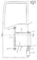
- Figs. 1 and 2 show a swing door 1 on a not shown otherwise in the vehicle of public transport.
- the seen in Fig. 1 from the inside of the vehicle fro swing door 1 is mounted on a support frame to a door frame 1.1.
- the support frame has a support tube 3, which is parallel to the pivot door 1 in the vertical direction and hinged at its two ends via hinges 3.1 and 3.2 with a vertical axis of rotation on the pivot door 1.
- On the support tube 3, a support member 4 is fixed, the structure will be explained in more detail below.
- the support element 4 is frictionally connected via a clamp 6 with a drive tube 2.
- the drive tube 2 also extends in the vertical direction parallel to the swing door leaf 1 and is rotatably mounted in a holder 2.1, which is attached to a connected to the door frame 1.1 vehicle structure.
- the drive tube 2 is rotated by a rotary drive 5 in rotation.
- the structure of the support member 4 is shown in FIGS. 2 and 3 and 5 in more detail.
- the support element 4 consists of a total of three extruded profile pieces 4.1, 4.2 and 4.3, of which the extruded 4.2 and 4.3 are integrally connected to each other and the extruded section 4.1 is attached as an additional piece with a narrow side to the opposite narrow side of the extruded section 4.2 and welded thereto.
- the narrow side of the extruded profile piece 4.2 is provided with a groove 8.2 and the narrow side of the extruded profile piece 4.1 with a spring 8.1. With this tongue and groove connection, the two extruded profile pieces are attached to each other and then welded together.
- the extruded profile pieces 4.1, 4.2 and 4.3 have in the usual way two equally spaced outer walls with arranged between them webs or side walls. This structure is shown in Fig. 3 closer, where, for example, the extruded section 4.2 has the outer walls 4.21 and 4.22, which are interconnected via webs 4.23 and kept at the same distance. The narrow side is completed with a side wall 4.24.
- the extruded profile pieces may be made of aluminum or an aluminum alloy, steel or a steel alloy or plastic.
- the clamp 6 has two legs 6.1 and 6.2, of which the leg 6.1 is integrated into the extruded section 4.3.
- the clamping is achieved by screw 7.1, 7.2 and 7.3.
- a strip-shaped cap 10 made of plastic etc. may be arranged.
- Fig. 4 shows that the supported with the support element described pivoting door can also be designed as a two-leaf pivoting door. 4 is in principle the same as described with reference to FIGS. 1 and 2, with the difference that the support member 4 'and 4A is slightly shorter by the shown in Fig. 2 additional piece 4.1 is missing ,
- the door thus has the two pivot door leaves 1 and 1A, a common door frame 1.1, two drive tubes 2 and 2A, two support tubes 3 and 3A, respectively, a support member 4 'and 4A, via the clamp 6 and 6A to the drive tube 2 and 2A is connected.
- a support member 4 'and 4A via the clamp 6 and 6A to the drive tube 2 and 2A is connected.
- the difference between the support members of the embodiment of FIG. 1 and 2 and the embodiment of FIG. 4 is again clearly visible.
- the additional piece 4.1 is attached to the parts 4.2 and 4.3 of the support element, as described above, while in the embodiment of Fig. 4, the support element is composed only of the parts 4.2 'and 4.3' ,
- a stop buffer 11 or 11A is arranged on the pivoting door leaf 1 or 1A facing inside of the extruded profile piece 4.3 or 4.3A.
- the support member may be formed in principle in the same manner as shown for example in Figs. 1 to 3.
- the arrangement is such that the support tube and the drive tube, which are designated in Figs. 1 and 2 by the reference numerals 3 and 2, not vertically, but horizontally, so that the pivoting flap is pivoted about a horizontal axis ,
Landscapes
- Engineering & Computer Science (AREA)
- Mechanical Engineering (AREA)
- Chemical & Material Sciences (AREA)
- Combustion & Propulsion (AREA)
- Transportation (AREA)
- Power-Operated Mechanisms For Wings (AREA)
- Shafts, Cranks, Connecting Bars, And Related Bearings (AREA)
- Laminated Bodies (AREA)
- Hinges (AREA)
- Gates (AREA)
- Support Devices For Sliding Doors (AREA)
- Window Of Vehicle (AREA)
Abstract
Description
Die Erfindung betrifft eine Schwenktür oder Schwenkklappe für Fahrzeuge des öffentlichen Personennahverkehrs mit mindestens einem Flügel, der mittels eines mit dem Flügel über mindestens ein Drehgelenk verbundenen Tragelements an einem parallel zum Schwenktürflügel angeordneten drehbaren Antriebsrohr befestigt ist.The invention relates to a hinged door or pivoting flap for vehicles of public transport with at least one wing, which is fastened by means of a connected to the wing via at least one hinge support member on a parallel to the pivot door pivotable drive tube.
Eine derartige Schwenktür ist beispielsweise in
Bei den bekannten Schwenktüren dieser Bauart besteht dasTragelement im allgemeinen aus einem Traggestell mit einem Tragrohr, das in vertikaler Richtung parallel zum Schwenktürflügel verläuft und an seinen beiden Enden über Drehgelenke mit vertikaler Drehachse am Schwenktürflügel angelenkt ist. Am Tragrohr sind zwei in unterschiedlichen horizontalen Ebenen liegenden Tragarme fest angeordnet. Die Tragarme sind jeweils über Klemmschellen kraftschlüssig mit dem Antriebsrohr verbunden.In the known swing doors of this type, the support member generally consists of a support frame with a support tube extending in the vertical direction parallel to the swing door leaf and on its two ends is articulated via swivel joints with a vertical axis of rotation on the pivot door wing. At the support tube lying in different horizontal planes two support arms are fixed. The support arms are each connected via clamps frictionally connected to the drive tube.
Der Erfindung liegt die Aufgabe zugrunde, eine Schwenktür oder Schwenkklappe mit den eingangs und im Oberbegriff des Patentanspruchs 1 angegebenen Merkmalen so auszubilden, dass das Tragelement in optisch besonders ansprechender Weise ausgestaltet werden kann. Weiterhin sollte eine Gewichtsreduzierung und eine Erleichterung bei der Montage erreicht werden.The invention has the object of providing a pivoting door or pivoting flap with the features specified in the preamble of
Die Lösung dieser Aufgabe geschieht erfindungsgemäß mit den Merkmalen aus dem kennzeichnenden Teil des Patentanspruchs 1. Vorteilhafte Weiterbildungen der Erfindung sind in den abhängigen Ansprüchen beschrieben.The solution of this object is achieved according to the invention with the features of the characterizing part of
Ein Grundgedanke der Erfindung besteht darin, das Tragelement nicht mit mehreren Tragarmen aufzubauen, sondern aus einem oder mehreren Strangpressprofilstücken. Wie weiter unten anhand von Ausführungsbeispielen näher erläutert, können die Strangpressprofilstücke so ausgebildet werden, dass sie sich über den ganzen Abstand erstrecken, der bei den bekannten Tragelementen zwischen den beiden Tragrohren entsteht. Dies eröffnet die Möglichkeit, das Tragelement optisch ansprechend zu gestalten, indem beispielsweise seine Vorderläche mit textilem Material verkleidet werden kann und zumindest die obere Kante der Strangpressprofilstücke mit einer streifenförmigen Abdeckkappe aus Kunststoff versehen werden kann. Die erfindungsgemäße Ausbildung des Tragelements bringt außer einer Gewichtsreduzierung noch ein erhöhtes Maß an Sicherheit, da es nun nicht mehr möglich ist, beispielsweise mit einem Bein oder einem Gepäckstück zwischen die beiden Tragarme zu geraten, was beim Öffnen der Schwenktür zu gefährlichen Unfällen führen kann. Weiterhin hat sich herausgestellt, dass die Montage der erfindungsgemäßen Schwenktür durch die besondere Ausbildung des Tragelements erheblich vereinfacht wird. Schließlich bringt der Aufbau des Tragelements aus ein oder mehreren Strangpressprofilstücken einen erheblichen Vorteil bei der Herstellung und Lagerhaltung. Bei herkömmlichen Schwenktüren müssen für unterschiedliche Türabmessungen Tragarme mit sehr unterschiedlichen Rohrlängen auf Lager gehalten werden. Beim Aufbau des Tragelements aus Strangpressprofilstücken ist es möglich, jeweils einfach Zusatzstücke anzuschweißen. Wie weiter unten erläutert, kann dabei in besonders vorteilhafter Weise das Aneinandersetzen der Strangpressprofilstücke derart erfolgen, dass die aneinander ansetzbaren Schmalseiten mit einer Nut-Feder-Verbindung versehen sind, so dass sie beim Aneinanderansetzen ineinandergreifen und dann in dieser Lage fixiert miteinander verschweißt oder verklebt werden können.A basic idea of the invention is not to construct the support element with a plurality of support arms, but from one or more extruded profile pieces. As explained in more detail below with reference to embodiments, the extruded profile pieces can be formed so that they extend over the entire distance that arises in the known support elements between the two support tubes. This opens up the possibility of making the support element visually appealing by, for example, its front surface can be covered with textile material and at least the upper edge of the extruded profile pieces can be provided with a strip-shaped cap made of plastic. The inventive construction of the support element brings in addition to a reduction in weight still an increased level of security, since it is no longer possible, for example, with a leg or a piece of luggage between the two arms, which can lead to dangerous accidents when you open the swing door. Furthermore, it has been found that the assembly of the pivoting door according to the invention is considerably simplified by the special design of the support element. Finally, the structure of the support element of one or more extruded profile pieces brings a considerable advantage in the production and storage. In conventional swing doors support arms with very different tube lengths must be kept in stock for different door dimensions. When constructing the support element of extruded profile pieces, it is possible to easily weld each additional pieces. As explained below, it can be done in a particularly advantageous manner the Aneinanderetzen the extruded sections such that the adjoining narrow sides are provided with a tongue and groove connection, so that they intermesh when juxtaposed and then fixed in this position welded or glued together can.
Die Erfindung ist sowohl bei Schwenktüren als auch bei Schwenkklappen, beispielsweise Kofferraumklappen an Autobussen, einsetzbar. Die Schwenktüren oder Schwenkklappen können motorisch oder manuell bewegbar sein.The invention can be used both with swing doors and with pivoting flaps, for example trunk flaps on buses. The swing doors or hinged flaps can be motorized or manually movable.
Im folgenden werden anhand der beigefügten Zeichnungen Ausführungsbeispiele für eine Schwenktür nach der Erfindung und ihrem Aufbau näher erläutert.In the following embodiments of a swing door according to the invention and its structure will be explained in more detail with reference to the accompanying drawings.
In den Zeichnungen zeigen:
- Fig. 1 einen Schwenktürflügel mit einem Tragelement zur Befestigung an einem Antriebsrohr;
- Fig. 2 einen Schnitt nach der Linie II-II in Fig. 1;
- Fig. 3 in perspektivischer, gegenüber Fig. 1 vergrößerter Darstellung das aus Strangpressprofilstücken zusammengesetzte Tragelement gemäß Fig. 1 und 2;
- Fig. 4 eine Ausführungsform der Schwenktür als zweiflüglige Tür;
- Fig. 5 in explodierter Darstellung das aus drei Strangpressprofilstücken zusammengesetzte Tragelement mit Tragrohr.
- Figure 1 shows a swing door leaf with a support member for attachment to a drive tube.
- Figure 2 is a section along the line II-II in Fig. 1.
- Fig. 3 in perspective, with respect to Figure 1 enlarged view of the composite of extruded profile pieces supporting element according to Figures 1 and 2.
- 4 shows an embodiment of the hinged door as a two-leaf door;
- Fig. 5 in an exploded view of the composite of three extruded profile pieces support member with support tube.
Die Fig. 1 und 2 zeigen einen Schwenktürflügel 1 an einem im übrigen nicht dargestellten Fahrzeug des öffentlichen Personennahverkehrs. Der in Fig. 1 von der Innenseite des Fahrzeugs her gesehene Schwenktürflügel 1 ist über ein Traggestell an einem Türrahmen 1.1 befestigt. Das Traggestell besitzt ein Tragrohr 3, das in vertikaler Richtung parallel zum Schwenktürflügel 1 verläuft und an seinen beiden Enden über Drehgelenke 3.1 und 3.2 mit vertikaler Drehachse am Schwenktürflügel 1 angelenkt ist. Am Tragrohr 3 ist ein Tragelement 4 fest angeordnet, dessen Aufbau weiter unten näher erläutert wird. Das Tragelement 4 ist über eine Klemmschelle 6 kraftschlüssig mit einem Antriebsrohr 2 verbunden. Das Antriebsrohr 2 verläuft ebenfalls in vertikaler Richtung parallel zum Schwenktürflügel 1 und ist in einer Halterung 2.1 drehbar gelagert, die an einer mit dem Türrahmen 1.1 verbundenen Fahrzeugstruktur befestigt ist. Das Antriebsrohr 2 wird von einem Drehantrieb 5 in Drehung versetzt.Figs. 1 and 2 show a
Der Aufbau des Tragelements 4 ist den Fig. 2 und 3 sowie 5 genauer zu entnehmen. Das Tragelement 4 besteht insgesamt aus drei Strangpressprofilstücken 4.1, 4.2 und 4.3, von denen die Strangpressprofilstücke 4.2 und 4.3 einstückig miteinander ver-bunden sind und das Strangpressprofilstück 4.1 als Zusatzstück mit einer Schmalseite an die gegenüberliegende Schmalseite des Strangpressprofilstücks 4.2 angesetzt und mit dieser verschweißt ist. Hierzu ist die Schmalseite des Strangpressprofilstücks 4.2 mit einer Nut 8.2 und die Schmalseite des Strangpressprofilstücks 4.1 mit einer Feder 8.1 versehen. Mit dieser Nut-Feder-Verbindung werden die beiden Strangpressprofilstücke aneinander angesetzt und dann miteinander verschweißt. Die Strangpressprofilstücke 4.1, 4.2 und 4.3 besitzen in üblicher Weise zwei in gleichem Abstand voneinander angeordnete Außenwände mit zwischen ihnen angeordneten Stegen bzw. Seitenwänden. Dieser Aufbau ist Fig. 3 genauer zu entnehmen, wo beispielsweise das Strangpressprofilstück 4.2 die Außenwände 4.21 und 4.22 besitzt, die über Stege 4.23 miteinander verbunden und auf gleichem Abstand gehalten sind. Die Schmalseite ist mit einer Seitenwand 4.24 abgeschlossen. Die Strangpressprofilstücke können aus Aluminium oder aus einer Aluminiumlegierung, aus Stahl oder einer Stahllegierung oder auch aus Kunststoff bestehen.The structure of the
Im Tragelement 4 sind die Strangpressprofilstücke in horizontaler Richtung aneinander anschließend miteinander verbunden.In the
Mit dem Antriebsrohr 2 ist das Tragelement 4 über eine einstückig ausgebildete Klemmschelle 6 kraftschlüssig verbunden. Die Klemmschelle 6 besitzt zwei Schenkel 6.1 und 6.2, von denen der Schenkel 6.1 in das Strangpressprofilstück 4.3 integriert ist. Die Klemmung wird durch Schraubverbindungen 7.1, 7.2 und 7.3 erreicht.With the
Zur optisch ansprechenden Gestaltung kann, wie in Fig. 1 angedeutet, mindestens die dem Fahrzeuginneren zugekehrte Oberfläche 9 des Tragelements 4 mit einer textilen Auflage, beispielsweise einer Teppichauflage, versehen sein, und an der oberen Schmalseite des Tragelements 4 kann eine streifenförmige Abdeckkappe 10 aus Kunststoff etc. angeordnet sein.For optically appealing design, as indicated in Fig. 1, at least the vehicle
Fig. 4 zeigt, dass die mit dem beschriebenen Tragelement gehalterte Schwenktür auch als zweiflüglige Schwenktür ausgebildet sein kann. Der Aufbau der zweiflügligen Schwenktür nach Fig. 4 ist im Prinzip der gleiche wie anhand der Fig. 1 und 2 geschildert, mit dem Unterschied, dass das Tragelement 4' bzw. 4A etwas kürzer ist, indem das in Fig. 2 dargestellte Zusatzstück 4.1 fehlt.Fig. 4 shows that the supported with the support element described pivoting door can also be designed as a two-leaf pivoting door. 4 is in principle the same as described with reference to FIGS. 1 and 2, with the difference that the support member 4 'and 4A is slightly shorter by the shown in Fig. 2 additional piece 4.1 is missing ,
Die Tür besitzt somit die beiden Schwenktürflügel 1 und 1A, einen gemeinsamen Türrahmen 1.1, zwei Antriebsrohre 2 bzw. 2A, zwei Tragrohre 3 bzw. 3A, jeweils ein Tragelement 4' bzw. 4A, das über die Klemmschelle 6 bzw. 6A mit dem Antriebsrohr 2 bzw. 2A verbunden ist. Aus Fig. 5 ist der Unterschied zwischen den Tragelementen der Ausführungsform nach Fig. 1 und 2 und der Ausführungsform nach Fig. 4 noch einmal gut zu ersehen. Im Falle der Ausführungsform nach Fig. 1 und 2 ist an die Teile 4.2 und 4.3 des Tragelements noch das Zusatzstück 4.1 angesetzt, wie oben beschrieben, während bei der Ausführungsform nach Fig. 4 das Tragelement nur aus den Teilen 4.2' und 4.3' aufgebaut ist.The door thus has the two
Bei allen dargestellten Ausführungsformen eines Schwenktürflügels ist an der dem Schwenktürflügel 1 bzw. 1A zugewandten Innenseite des Strangpressprofilstücks 4.3 bzw. 4.3A ein Anschlagpuffer 11 bzw. 11A angeordnet.In all the illustrated embodiments of a swing door leaf, a
Bei einem nicht dargestellten Ausführungsbeispiel für eine Schwenkklappe, beispielsweise eine Kofferraumklappe für einen Autobus, kann das Tragelement prinzipiell in der gleichen Weise ausgebildet sein wie beispielsweise in den Fig. 1 bis 3 dargestellt. In einem solchen Falle ist die Anordnung derart, dass das Tragrohr und das Antriebsrohr, die in den Fig.1 und 2 mit den Bezugsziffern 3 und 2 bezeichnet sind, nicht vertikal, sondern horizontal verlaufen, so dass die Schwenkklappe um eine horizontale Achse verschwenkt wird.In an embodiment, not shown, for a pivoting flap, such as a trunk lid for a bus, the support member may be formed in principle in the same manner as shown for example in Figs. 1 to 3. In such a case, the arrangement is such that the support tube and the drive tube, which are designated in Figs. 1 and 2 by the
Claims (14)
- Pivoting door or pivoting flap for local public transport vehicles with at least one wing (1) which is fastened to a rotatable drive tube (2) disposed parallel to the wing by means of a support element (4) connected to the wing via at least one pivot joint (3.1, 3.2), characterised in that the support element (4) is formed from at least one extruded section (4.1, 4.2, 4.3) of a predetermined height and width.
- Pivoting door or pivoting flap according to Claim 1, characterised in that the extruded section (4.2) has two outer plates (4.21, 4.22) which are disposed at a uniform spacing from one another and have webs (4.23) or side walls (4.24) disposed between them.
- Pivoting door or pivoting flap according to Claim 1 or 2, characterised in that the extruded section (4.1, 4.2, 4.3) consists of aluminium or an aluminium alloy.
- Pivoting door or pivoting flap according to Claim 1 or 2, characterised in that the extruded section (4.1, 4.2, 4.3) consists of steel or a steel alloy.
- Pivoting door or pivoting flap according to either of Claims 1 and 2, characterised in that the extruded section (4.1, 4.2, 4.3) consists of plastics material.
- Pivoting door or pivoting flap according to any one of Claims 1 to 5, characterised in that the support element (4) is constructed from two or more extruded sections (4.1, 4.2, 4.3) which are fastened to one another.
- Pivoting door or pivoting flap according to Claim 6, characterised in that the support element (4) is constructed from two or more extruded sections (4.1, 4.2, 4.3) which are adjacent to one another in the horizontal direction.
- Pivoting door or pivoting flap according to Claim 7, characterised in that the adjacent extruded sections (4.1, 4.2) are fixed to one another by means of a tongue and groove joint (8.1 - 8.2) and welded or glued together.
- Pivoting door or pivoting flap according to any one of Claims 1 to 8, characterised in that the support element (4) is non-positively connected to the drive tube (2) via at least one clamping clip (6).
- Pivoting door or pivoting flap according to Claim 9, characterised in that the clamping clip (6) is of integral formation and is fastened to the extruded section (4.3) in the region of its one free leg (6.1).
- Pivoting door or pivoting flap according to Claim 9, characterised in that the clamping clip is of integral formation and is fastened to the extruded section in the region of its plane of symmetry.
- Pivoting door or pivoting flap according to any one of Claims 1 to 11, characterised in that the support element (4) is provided on at least one of its outer sides (9) with a covering of textile material or plastics material.
- Pivoting door or pivoting flap according to any one of Claims 1 to 12, characterised in that the support element (4) is provided on at least one of its narrow sides at the top and/or bottom edge with a strip-shaped cover cap (10).
- Pivoting door according to any one of Claims 1 to 13, characterised in that the support element (4) is connected to the pivoting door wing (1) via at least one pivot joint (3.1, 3.2) with a vertical axis of rotation and is fastened to a rotatable, motor-driven drive tube (2) which is disposed vertically and parallel to the pivoting door wing (1) .
Priority Applications (1)
| Application Number | Priority Date | Filing Date | Title |
|---|---|---|---|
| PL04027951T PL1547835T3 (en) | 2003-12-24 | 2004-11-25 | Pivoting door wing for public transport vehicles |
Applications Claiming Priority (2)
| Application Number | Priority Date | Filing Date | Title |
|---|---|---|---|
| DE20320029U DE20320029U1 (en) | 2003-12-24 | 2003-12-24 | Swing door or swivel flap for public transport vehicles |
| DE20320029U | 2003-12-24 |
Publications (3)
| Publication Number | Publication Date |
|---|---|
| EP1547835A2 EP1547835A2 (en) | 2005-06-29 |
| EP1547835A3 EP1547835A3 (en) | 2007-02-21 |
| EP1547835B1 true EP1547835B1 (en) | 2008-01-09 |
Family
ID=32186159
Family Applications (1)
| Application Number | Title | Priority Date | Filing Date |
|---|---|---|---|
| EP04027951A Not-in-force EP1547835B1 (en) | 2003-12-24 | 2004-11-25 | Pivoting door wing for public transport vehicles |
Country Status (5)
| Country | Link |
|---|---|
| EP (1) | EP1547835B1 (en) |
| AT (1) | ATE383262T1 (en) |
| DE (2) | DE20320029U1 (en) |
| ES (1) | ES2299784T3 (en) |
| PL (1) | PL1547835T3 (en) |
Families Citing this family (2)
| Publication number | Priority date | Publication date | Assignee | Title |
|---|---|---|---|---|
| DE102004062485A1 (en) * | 2004-12-24 | 2006-07-13 | Daimlerchrysler Ag | vehicle door |
| US9353566B2 (en) * | 2013-08-30 | 2016-05-31 | Magna Closures Inc. | Power door actuation system |
Family Cites Families (3)
| Publication number | Priority date | Publication date | Assignee | Title |
|---|---|---|---|---|
| DE3705369A1 (en) * | 1987-02-20 | 1988-09-01 | Bode & Co Geb | ROTARY DRIVE FOR MOVING A SWIVEL DOOR, ESPECIALLY ON VEHICLES |
| IT1260120B (en) * | 1992-07-21 | 1996-03-28 | Ermanno Righi | VEHICLE DOOR SWING DRIVE DEVICE |
| ITTO20010757A1 (en) * | 2001-07-31 | 2003-01-31 | Oclap Srl | DEVICE FOR OPENING AND CLOSING A ROTATING-TRANSLATING DOOR FOR MOTOR VEHICLES. |
-
2003
- 2003-12-24 DE DE20320029U patent/DE20320029U1/en not_active Expired - Lifetime
-
2004
- 2004-11-25 ES ES04027951T patent/ES2299784T3/en active Active
- 2004-11-25 EP EP04027951A patent/EP1547835B1/en not_active Not-in-force
- 2004-11-25 DE DE502004005897T patent/DE502004005897D1/en active Active
- 2004-11-25 PL PL04027951T patent/PL1547835T3/en unknown
- 2004-11-25 AT AT04027951T patent/ATE383262T1/en not_active IP Right Cessation
Also Published As
| Publication number | Publication date |
|---|---|
| EP1547835A2 (en) | 2005-06-29 |
| PL1547835T3 (en) | 2008-06-30 |
| EP1547835A3 (en) | 2007-02-21 |
| DE20320029U1 (en) | 2004-04-22 |
| DE502004005897D1 (en) | 2008-02-21 |
| ES2299784T3 (en) | 2008-06-01 |
| ATE383262T1 (en) | 2008-01-15 |
Similar Documents
| Publication | Publication Date | Title |
|---|---|---|
| EP0014361B1 (en) | Slidable folding door | |
| EP0483533B1 (en) | Vehicle cabin, particularly for an industrial tractor unit | |
| EP0059361A2 (en) | Rear window for an agricultural tractor cab | |
| EP1669231A2 (en) | Sliding and folding door for automotive vehicles | |
| EP1108849B1 (en) | Door leaf of a sectional door | |
| DE4244233A1 (en) | ||
| DE69606793T2 (en) | Improved movement device for opening and closing a wardrobe door | |
| DE3317341C2 (en) | Motor vehicle door | |
| DE68917057T2 (en) | Motor vehicle with sliding doors. | |
| DE1584080A1 (en) | Suspension for swing doors | |
| EP1547835B1 (en) | Pivoting door wing for public transport vehicles | |
| DE4216689A1 (en) | Concealed hinge joint | |
| DE202006003330U1 (en) | Sectional door of linked panels with a vertical movement, together with a slip door of linked panels, has hinges for the slip door panels on swing axes at the front side of the door | |
| DE19600553C1 (en) | Cover for gate hinge, especially for sectional gate hinges | |
| EP0702124B1 (en) | Finger guard for sectional doors | |
| CH655762A5 (en) | Folding sliding part for external and internal walls of buildings | |
| DE69724084T2 (en) | sectional doors | |
| EP1036700B1 (en) | External door for a camper, caravan or the like | |
| EP1516763B1 (en) | Body structure | |
| DE19745032B4 (en) | Hinge assembly for the pivotable articulation of a door or tailgate on a body part of a motor vehicle | |
| EP0976594A1 (en) | Cargo door | |
| DE2645671A1 (en) | Up-and-over garage door - is opened by individual door panels pivoting relative to each other when door is pushed up along runners | |
| DE3333215A1 (en) | Spoiler | |
| DE9217845U1 (en) | Moulded plastic box with hinged wall | |
| DE20316761U1 (en) | Arrangement for fixing hinged folding door, especially for motor vehicle of public transport, to actuation tube, has clamp that connects carrier arm to actuation tube and that consists of two pieces |
Legal Events
| Date | Code | Title | Description |
|---|---|---|---|
| PUAI | Public reference made under article 153(3) epc to a published international application that has entered the european phase |
Free format text: ORIGINAL CODE: 0009012 |
|
| AK | Designated contracting states |
Kind code of ref document: A2 Designated state(s): AT BE BG CH CY CZ DE DK EE ES FI FR GB GR HU IE IS IT LI LU MC NL PL PT RO SE SI SK TR |
|
| AX | Request for extension of the european patent |
Extension state: AL HR LT LV MK YU |
|
| PUAL | Search report despatched |
Free format text: ORIGINAL CODE: 0009013 |
|
| AK | Designated contracting states |
Kind code of ref document: A3 Designated state(s): AT BE BG CH CY CZ DE DK EE ES FI FR GB GR HU IE IS IT LI LU MC NL PL PT RO SE SI SK TR |
|
| AX | Request for extension of the european patent |
Extension state: AL HR LT LV MK YU |
|
| 17P | Request for examination filed |
Effective date: 20070419 |
|
| GRAP | Despatch of communication of intention to grant a patent |
Free format text: ORIGINAL CODE: EPIDOSNIGR1 |
|
| AKX | Designation fees paid |
Designated state(s): AT BE BG CH CY CZ DE DK EE ES FI FR GB GR HU IE IS IT LI LU MC NL PL PT RO SE SI SK TR |
|
| GRAS | Grant fee paid |
Free format text: ORIGINAL CODE: EPIDOSNIGR3 |
|
| GRAA | (expected) grant |
Free format text: ORIGINAL CODE: 0009210 |
|
| AK | Designated contracting states |
Kind code of ref document: B1 Designated state(s): AT BE BG CH CY CZ DE DK EE ES FI FR GB GR HU IE IS IT LI LU MC NL PL PT RO SE SI SK TR |
|
| REG | Reference to a national code |
Ref country code: GB Ref legal event code: FG4D Free format text: NOT ENGLISH |
|
| REG | Reference to a national code |
Ref country code: CH Ref legal event code: EP |
|
| REG | Reference to a national code |
Ref country code: IE Ref legal event code: FG4D Free format text: LANGUAGE OF EP DOCUMENT: GERMAN |
|
| REF | Corresponds to: |
Ref document number: 502004005897 Country of ref document: DE Date of ref document: 20080221 Kind code of ref document: P |
|
| GBT | Gb: translation of ep patent filed (gb section 77(6)(a)/1977) |
Effective date: 20080204 |
|
| PG25 | Lapsed in a contracting state [announced via postgrant information from national office to epo] |
Ref country code: SI Free format text: LAPSE BECAUSE OF FAILURE TO SUBMIT A TRANSLATION OF THE DESCRIPTION OR TO PAY THE FEE WITHIN THE PRESCRIBED TIME-LIMIT Effective date: 20080109 |
|
| REG | Reference to a national code |
Ref country code: ES Ref legal event code: FG2A Ref document number: 2299784 Country of ref document: ES Kind code of ref document: T3 |
|
| REG | Reference to a national code |
Ref country code: PL Ref legal event code: T3 |
|
| PG25 | Lapsed in a contracting state [announced via postgrant information from national office to epo] |
Ref country code: IS Free format text: LAPSE BECAUSE OF FAILURE TO SUBMIT A TRANSLATION OF THE DESCRIPTION OR TO PAY THE FEE WITHIN THE PRESCRIBED TIME-LIMIT Effective date: 20080509 Ref country code: FI Free format text: LAPSE BECAUSE OF FAILURE TO SUBMIT A TRANSLATION OF THE DESCRIPTION OR TO PAY THE FEE WITHIN THE PRESCRIBED TIME-LIMIT Effective date: 20080109 |
|
| PG25 | Lapsed in a contracting state [announced via postgrant information from national office to epo] |
Ref country code: BG Free format text: LAPSE BECAUSE OF FAILURE TO SUBMIT A TRANSLATION OF THE DESCRIPTION OR TO PAY THE FEE WITHIN THE PRESCRIBED TIME-LIMIT Effective date: 20080409 |
|
| ET | Fr: translation filed | ||
| PG25 | Lapsed in a contracting state [announced via postgrant information from national office to epo] |
Ref country code: PT Free format text: LAPSE BECAUSE OF FAILURE TO SUBMIT A TRANSLATION OF THE DESCRIPTION OR TO PAY THE FEE WITHIN THE PRESCRIBED TIME-LIMIT Effective date: 20080609 |
|
| REG | Reference to a national code |
Ref country code: IE Ref legal event code: FD4D |
|
| PG25 | Lapsed in a contracting state [announced via postgrant information from national office to epo] |
Ref country code: SK Free format text: LAPSE BECAUSE OF FAILURE TO SUBMIT A TRANSLATION OF THE DESCRIPTION OR TO PAY THE FEE WITHIN THE PRESCRIBED TIME-LIMIT Effective date: 20080109 Ref country code: IE Free format text: LAPSE BECAUSE OF FAILURE TO SUBMIT A TRANSLATION OF THE DESCRIPTION OR TO PAY THE FEE WITHIN THE PRESCRIBED TIME-LIMIT Effective date: 20080109 Ref country code: SE Free format text: LAPSE BECAUSE OF FAILURE TO SUBMIT A TRANSLATION OF THE DESCRIPTION OR TO PAY THE FEE WITHIN THE PRESCRIBED TIME-LIMIT Effective date: 20080409 Ref country code: DK Free format text: LAPSE BECAUSE OF FAILURE TO SUBMIT A TRANSLATION OF THE DESCRIPTION OR TO PAY THE FEE WITHIN THE PRESCRIBED TIME-LIMIT Effective date: 20080109 |
|
| PLBE | No opposition filed within time limit |
Free format text: ORIGINAL CODE: 0009261 |
|
| STAA | Information on the status of an ep patent application or granted ep patent |
Free format text: STATUS: NO OPPOSITION FILED WITHIN TIME LIMIT |
|
| PG25 | Lapsed in a contracting state [announced via postgrant information from national office to epo] |
Ref country code: RO Free format text: LAPSE BECAUSE OF FAILURE TO SUBMIT A TRANSLATION OF THE DESCRIPTION OR TO PAY THE FEE WITHIN THE PRESCRIBED TIME-LIMIT Effective date: 20080109 |
|
| 26N | No opposition filed |
Effective date: 20081010 |
|
| PG25 | Lapsed in a contracting state [announced via postgrant information from national office to epo] |
Ref country code: EE Free format text: LAPSE BECAUSE OF FAILURE TO SUBMIT A TRANSLATION OF THE DESCRIPTION OR TO PAY THE FEE WITHIN THE PRESCRIBED TIME-LIMIT Effective date: 20080109 |
|
| PG25 | Lapsed in a contracting state [announced via postgrant information from national office to epo] |
Ref country code: MC Free format text: LAPSE BECAUSE OF NON-PAYMENT OF DUE FEES Effective date: 20081130 |
|
| REG | Reference to a national code |
Ref country code: CH Ref legal event code: PL |
|
| PG25 | Lapsed in a contracting state [announced via postgrant information from national office to epo] |
Ref country code: CY Free format text: LAPSE BECAUSE OF FAILURE TO SUBMIT A TRANSLATION OF THE DESCRIPTION OR TO PAY THE FEE WITHIN THE PRESCRIBED TIME-LIMIT Effective date: 20080109 |
|
| PG25 | Lapsed in a contracting state [announced via postgrant information from national office to epo] |
Ref country code: LI Free format text: LAPSE BECAUSE OF NON-PAYMENT OF DUE FEES Effective date: 20081130 Ref country code: CH Free format text: LAPSE BECAUSE OF NON-PAYMENT OF DUE FEES Effective date: 20081130 |
|
| PG25 | Lapsed in a contracting state [announced via postgrant information from national office to epo] |
Ref country code: AT Free format text: LAPSE BECAUSE OF NON-PAYMENT OF DUE FEES Effective date: 20081125 |
|
| PG25 | Lapsed in a contracting state [announced via postgrant information from national office to epo] |
Ref country code: HU Free format text: LAPSE BECAUSE OF FAILURE TO SUBMIT A TRANSLATION OF THE DESCRIPTION OR TO PAY THE FEE WITHIN THE PRESCRIBED TIME-LIMIT Effective date: 20080710 Ref country code: LU Free format text: LAPSE BECAUSE OF NON-PAYMENT OF DUE FEES Effective date: 20081125 |
|
| PG25 | Lapsed in a contracting state [announced via postgrant information from national office to epo] |
Ref country code: GR Free format text: LAPSE BECAUSE OF FAILURE TO SUBMIT A TRANSLATION OF THE DESCRIPTION OR TO PAY THE FEE WITHIN THE PRESCRIBED TIME-LIMIT Effective date: 20080410 |
|
| PGFP | Annual fee paid to national office [announced via postgrant information from national office to epo] |
Ref country code: CZ Payment date: 20131114 Year of fee payment: 10 Ref country code: FR Payment date: 20131119 Year of fee payment: 10 Ref country code: DE Payment date: 20131126 Year of fee payment: 10 Ref country code: GB Payment date: 20131122 Year of fee payment: 10 |
|
| PGFP | Annual fee paid to national office [announced via postgrant information from national office to epo] |
Ref country code: BE Payment date: 20131121 Year of fee payment: 10 Ref country code: IT Payment date: 20131125 Year of fee payment: 10 Ref country code: NL Payment date: 20131120 Year of fee payment: 10 Ref country code: ES Payment date: 20131120 Year of fee payment: 10 Ref country code: TR Payment date: 20131118 Year of fee payment: 10 Ref country code: PL Payment date: 20131113 Year of fee payment: 10 |
|
| REG | Reference to a national code |
Ref country code: DE Ref legal event code: R119 Ref document number: 502004005897 Country of ref document: DE |
|
| REG | Reference to a national code |
Ref country code: NL Ref legal event code: V1 Effective date: 20150601 |
|
| PG25 | Lapsed in a contracting state [announced via postgrant information from national office to epo] |
Ref country code: BE Free format text: LAPSE BECAUSE OF NON-PAYMENT OF DUE FEES Effective date: 20141130 |
|
| GBPC | Gb: european patent ceased through non-payment of renewal fee |
Effective date: 20141125 |
|
| PG25 | Lapsed in a contracting state [announced via postgrant information from national office to epo] |
Ref country code: CZ Free format text: LAPSE BECAUSE OF NON-PAYMENT OF DUE FEES Effective date: 20141125 |
|
| REG | Reference to a national code |
Ref country code: FR Ref legal event code: ST Effective date: 20150731 |
|
| PG25 | Lapsed in a contracting state [announced via postgrant information from national office to epo] |
Ref country code: NL Free format text: LAPSE BECAUSE OF NON-PAYMENT OF DUE FEES Effective date: 20150601 |
|
| PG25 | Lapsed in a contracting state [announced via postgrant information from national office to epo] |
Ref country code: DE Free format text: LAPSE BECAUSE OF NON-PAYMENT OF DUE FEES Effective date: 20150602 Ref country code: GB Free format text: LAPSE BECAUSE OF NON-PAYMENT OF DUE FEES Effective date: 20141125 |
|
| PG25 | Lapsed in a contracting state [announced via postgrant information from national office to epo] |
Ref country code: FR Free format text: LAPSE BECAUSE OF NON-PAYMENT OF DUE FEES Effective date: 20141201 |
|
| PG25 | Lapsed in a contracting state [announced via postgrant information from national office to epo] |
Ref country code: IT Free format text: LAPSE BECAUSE OF NON-PAYMENT OF DUE FEES Effective date: 20141125 |
|
| REG | Reference to a national code |
Ref country code: ES Ref legal event code: FD2A Effective date: 20160129 |
|
| PG25 | Lapsed in a contracting state [announced via postgrant information from national office to epo] |
Ref country code: PL Free format text: LAPSE BECAUSE OF NON-PAYMENT OF DUE FEES Effective date: 20141125 |
|
| PG25 | Lapsed in a contracting state [announced via postgrant information from national office to epo] |
Ref country code: ES Free format text: LAPSE BECAUSE OF NON-PAYMENT OF DUE FEES Effective date: 20141126 |
|
| PG25 | Lapsed in a contracting state [announced via postgrant information from national office to epo] |
Ref country code: TR Free format text: LAPSE BECAUSE OF NON-PAYMENT OF DUE FEES Effective date: 20141125 |