EP1547703A1 - Abstreifvorrichtung für Stanzstempel - Google Patents
Abstreifvorrichtung für Stanzstempel Download PDFInfo
- Publication number
- EP1547703A1 EP1547703A1 EP20040015329 EP04015329A EP1547703A1 EP 1547703 A1 EP1547703 A1 EP 1547703A1 EP 20040015329 EP20040015329 EP 20040015329 EP 04015329 A EP04015329 A EP 04015329A EP 1547703 A1 EP1547703 A1 EP 1547703A1
- Authority
- EP
- European Patent Office
- Prior art keywords
- punch
- stripper
- pierce
- work
- pierce punch
- Prior art date
- Legal status (The legal status is an assumption and is not a legal conclusion. Google has not performed a legal analysis and makes no representation as to the accuracy of the status listed.)
- Granted
Links
Images


Classifications
-
- B—PERFORMING OPERATIONS; TRANSPORTING
- B21—MECHANICAL METAL-WORKING WITHOUT ESSENTIALLY REMOVING MATERIAL; PUNCHING METAL
- B21D—WORKING OR PROCESSING OF SHEET METAL OR METAL TUBES, RODS OR PROFILES WITHOUT ESSENTIALLY REMOVING MATERIAL; PUNCHING METAL
- B21D45/00—Ejecting or stripping-off devices arranged in machines or tools dealt with in this subclass
- B21D45/003—Ejecting or stripping-off devices arranged in machines or tools dealt with in this subclass in punching machines or punching tools
- B21D45/006—Stripping-off devices
-
- Y—GENERAL TAGGING OF NEW TECHNOLOGICAL DEVELOPMENTS; GENERAL TAGGING OF CROSS-SECTIONAL TECHNOLOGIES SPANNING OVER SEVERAL SECTIONS OF THE IPC; TECHNICAL SUBJECTS COVERED BY FORMER USPC CROSS-REFERENCE ART COLLECTIONS [XRACs] AND DIGESTS
- Y10—TECHNICAL SUBJECTS COVERED BY FORMER USPC
- Y10T—TECHNICAL SUBJECTS COVERED BY FORMER US CLASSIFICATION
- Y10T83/00—Cutting
- Y10T83/869—Means to drive or to guide tool
- Y10T83/8821—With simple rectilinear reciprocating motion only
- Y10T83/8841—Tool driver movable relative to tool support
-
- Y—GENERAL TAGGING OF NEW TECHNOLOGICAL DEVELOPMENTS; GENERAL TAGGING OF CROSS-SECTIONAL TECHNOLOGIES SPANNING OVER SEVERAL SECTIONS OF THE IPC; TECHNICAL SUBJECTS COVERED BY FORMER USPC CROSS-REFERENCE ART COLLECTIONS [XRACs] AND DIGESTS
- Y10—TECHNICAL SUBJECTS COVERED BY FORMER USPC
- Y10T—TECHNICAL SUBJECTS COVERED BY FORMER US CLASSIFICATION
- Y10T83/00—Cutting
- Y10T83/869—Means to drive or to guide tool
- Y10T83/8821—With simple rectilinear reciprocating motion only
- Y10T83/8841—Tool driver movable relative to tool support
- Y10T83/8853—Including details of guide for tool or tool support
Definitions
- the present invention relates to a punch stripper, which is structured by uniting a conventional piercing punch and a conventional stripper.
- a conventional piecing process is executed as shown in Fig. 19.
- a work W is mounted on a work supporting member 102 firmly fixed to a lower die base plate 101, a pad 103 pressing the work W is hanged downward from a hanging bolt 105 provided in an upper die base plate 104, the pad 103 is energized toward a lower side by a coil spring 106 contracted between the pad 103 and the upper die base plate 104, and the work W is pressed.
- a piece punch 107 is firmly fixed to a lower surface of the upper die base plate 104 in a downward handing manner by a retainer 108.
- the piercing process is executed by mounting the work W on the work supporting member 102 and downward moving an upper die 109. Then, the pad 103 first presses the work W, the work W is pierced by the piece punch 107 in accordance with a continuous downward movement of the upper die 109, and the upper die 109 reaches a bottom dead center state shown in Fig. 19.
- the pad 103 presses the work W for stabilizing before the piercing operation by the pierce punch 107, in order to allow the pierce punch 107 to pierce. Further, the pad 103 has a function of taking away the work W from the pierce punch 107 after being pierced by the pierce punch 107.
- the pad which presses the work and takes the work away from the pierce punch is constituted by a large block body and is manufactured normally by a cast metal.
- the pad is constituted by the large block body, is heavy, and has increased portions to be machined, whereby an expensive press die is structured.
- An illustrated example in Fig. 19 shows an example in which the portion to be pierced is a flat surface, however, the pierced portion is normally constituted by a three-dimensional curved surface, so that the pad is formed in accordance with an expensive copying process.
- cams such as a passive cam, an actuating cam and the like are used at the time of piercing a side surface of the work as shown in Fig. 18, the standardization of the cam relevant parts has been already achieved, and a high efficiency has been achieved in the design, the manufacture and the product control. However, an association between the standard of the cam relevant parts and the standard of the pierce relevant parts is not achieved.
- the present invention has been developed taking the matters mentioned above into consideration and for the following purposes.
- a punch stripper comprising a pierce punch, a punch retainer holding the pierce punch, a cover which covers the pierce punch so as to protrude a leading end portion of the pierce punch, and is fastened by screws to the punch retainer, a stripper which is outward fitted to the pierce punch, presses the work before piercing the work by the pierce punch, takes out the pierce punch from the work after piercing, is received within the cover so as to move forward and backward, and forms a stop flange in a rear end, and a coil spring which is received within the cover so as to bring the stripper into contact with the stop flange, and energizes the stripper toward an outer side.
- a punch stripper wherein the fitted portion between the stripper and the cover is formed in a non-circular cross sectional shape for preventing the stripper from rotating.
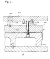
- Fig. 1 is a front elevational cross sectional view of a top dead center state of a pierce die to which a punch stripper in accordance with the present invention is attached
- Fig. 2 is a front elevational cross sectional view of a bottom dead center state of the pierce die in Fig. 1.
- a work W is mounted on a work supporting member 42 firmly fixed to a lower die base plate 41, and a punch stripper 43 applying a piercing process to the work W is firmly fixed to an upper die base plate 44.
- the piercing process is executed by mounting the work W on the work supporting member 42 and downward moving an upper die 45, whereby a stripper 5 first presses the work W, the work W is pierced by a piece punch 1 in accordance with a continuous downward movement of the upper die 45, and the upper die 45 reaches a bottom dead center state shown in Fig. 2.
- the stripper 5 presses the work W for stabilizing before the piercing operation by the pierce punch 1, in order to allow the pierce punch 1 to pierce. Further, the stripper 5 has a function of taking away the work W from the pierce punch 1 after being pierced by the pierce punch 1.
- Fig. 3 is a front elevational view of an assembly of a specific embodiment of the punch stripper in accordance with the present invention
- Fig. 4 is a plan view of the assembly in Fig. 3.
- the punch stripper in accordance with the present invention is constituted by a pierce punch 1, a punch retainer 2 holding the pierce punch 1, a cover 3 which covers the pierce punch 1 so as to protrude a leading end portion of the pierce punch 1, and is fastened by screws to the punch retainer 2, a stripper 5 which is outward fitted to the pierce punch 1, presses the work W before piercing the work W by the pierce punch 1, takes out the pierce punch 1 from the work W after piercing, is received within the cover 3 so as to move forward and backward, and forms a stop flange 4 in a rear end, and a coil spring 6 which is received within the cover 3 so as to bring the stripper 5 into contact with the stop flange 4, and energizes the stripper 5 toward an outer side.
- the pierce punch 1 is hardened and ground by a tool steel, and is held to the punch retainer 2 shown in Figs. 5 and 6.
- the punch retainer 2 is a plate-like body which is approximately in a triangular shape in a plan view, and is structured such that a holding hole 7 is pierced near a corner, and the pierce punch 1 is pressure inserted to and raised up in the holding hole 7.
- An engagement flange 8 in a base end of the pierce punch 1 is positioned within an enlarged hole 9.
- Bolt holes 10 are pierced near the other two corners, and the punch retainer is fastened to the upper die base plate 41 by bolts (not shown).
- a bolt hole 23 fastens the cover 3 mentioned below.
- the cover 3 covers the pierce punch 1, and is constituted by a tube portion 12 to which the leading end of the pierce punch 1 is protruded, and a mounting portion 13 which is extended to a side portion from the tube portion 12 for fastening the cover 3 to the punch retainer 2 by screws.
- the tube portion 12 moves the stripper 5 forward andbackward, and forms a receiving chamber 14 capable of receiving the coil spring 6, and an oval hole 16 for preventing the stripper 5 from rotating is pierced in an upper wall 15 of the receiving chamber 14.
- An engagement protruding piece 22 engaging with the punch retainer 2 is protruded from a leading end of the mounting portion 13, amounting hole 19 through which a positioning and mounting bolt 18 shown in Figs. 9 and 10 is inserted is pierced in a center portion 13 of the mounting portion, and the positioning and mounting bolt 18 is inserted through the mounting hole 19 so as to be engaged with a thread hole 23 in the punch retainer 2.
- the stripper 5 is outward fitted to the pierce punch 1, presses the work W before piercing the work W by means of the pierce punch 1, takes out the pierce punch 1 from the work W after piercing, is received within the cover 3 so as to move forward and backward, and forms the stop flange 4 at a rear end.
- the stripper 5 is received within the receiving chamber 14 of the cover 3 and engages the stop flange 4 at the rear end with the upper wall 15 so as to be protruded forward from the cover 3.
- An upper end of the coil spring 6 which is received within the receiving chamber 14 of the cover 3 in a contracted manner is brought into contact with the stop flange 4 so as to energize the stripper 5 toward an outer side.
- the pierce punch 1 pierces the work.
- the upper die 45 further moves downward, the pierce punch 1 protrudes into the work.
- the stripper 5 takes away the work W from the pierce punch 1 because the stripper 5 is energized toward the outer side by the coil spring 6.
- the receiving chamber 14 of the cover 3 is set so as to apply a stroke required for the pressing force before the work W is pierced, and a stroke required for the take-away force for taking away the work W from the piece punch 1 after the work W is pierced, to the stripper 5.
- the pierce punch pierces a non-circular hole such as a rectangular and the other shapes than a round hole
- a rotation stop for the pierce punch is required.
- the stripper 5 is formed on an oval diameter outer peripheral surface 21 so as to be fitted to the oval hole 16 of the cover 3.
- the leading end surface 17 of the pierce punch 1 is initially immersed into the stripper 5, however, when the upper die 45 moves downward so as to be brought into contact with the work W, the pierce punch 1 moves forward into the receiving chamber 14 of the cover 3, the pierce punch 1 is energized toward the outer side by the coil spring 6, the work W is energized by the stripper 5, and the work W is stabilized before the work W is pierced by the pierce punch 1.
- the stripper 5 takes away the pierce punch 1 from the work W because the stripper 5 is energized by the coil spring 6.
- the leading end surface 17 of the stripper 5 is subjected to the copying process after the punch stripper is mounted to the lower die base plate 41, whereby the leading end surface 17 of the stripper 5 is sufficiently brought into contact with the three-dimensional curved surface of the work.
- the leading end surface 20 of the piece punch 1 keeps a flat surface, and a sufficient piercing process can be executed by an angle of incline of 10 degree.
- the punch stripper mentioned above is of the main body mounting type.
- a punch retainer and a stripper of the outward mounting type punch stripper are absolutely the same as those of the main body mounting type punch stripper, however, a cover thereof is different therefrom.
- the outward mounting type punch stripper is constituted by a pierce punch 31, a punch retainer 2 which holds the pierce punch 31, a cover 32 which covers the pierce punch 31, protrudes a leading end portion of the pierce punch 31 and is fastened by screw to the punch retainer 2, a stripper 5 which is outward fitted to the pierce punch 31, presses the work before the work is pierced by the pierce punch 31, takes out the pierce punch from the work after piercing, is received within the cover 32 so as to be moved forward and backward, and forms a stop flange 4 at a rear end, and a coil spring 6 which is received within the cover 32, is brought into contact with the stop flange 4 of the stripper 5 and energizes the stripper 5 toward an outer side.
- the cover 31 is constituted by a tube body 33 which covers the pierce punch 31 and protrudes the leading end of the pierce punch 31, and a mounting portion 34 which extends to a lower side portion of the tube body 33 for fastening by screw the cover 31 to the outward mounting portion.
- the tube body 33 is absolutely the same as the tube body 12 of the main body mounting type, and the same reference numeral is attached thereto.
- a bolt hole 35 for fastening by screw to the outward mounting portion and a knock pin hole 36 for positioning are pierced in the mounting portion 34.
- Fig. 18 shows a bottom dead center state.
- the work W is mounted on a work supporting member 42 firmly fixed to a lower die base plate 41, a heel 51 is firmly fixed to the lower die base plate 41, the heel 51 is provided slidably with a passive cam 53 which is energized to an outer side (in a right direction as facing to the drawing) by an elastic coil spring 52, and the passive cam 53 is brought into contact with a stop plate 54 of the heel 51 at a position where an upper die 45 is positioned at a top dead center.
- An actuating cam 55 driven while being brought into contact with the passive cam 53 is firmly fixed to an upper die base plate 44.
- the punch retainer 2 holding the pierce punch 31 is firmly fixed to the passive cam 53, a stripper 17 which is outward fitted to the pierce punch 31 and is energized in a direction of the work W by the coil spring 6 is provided, and the cover 32 which is outward fitted to the stripper 17 and guides the stripper 17 is firmly fixed to the passive cam 53.
- the pierce punch 31 In a state in which the upper die 45 is at the top dead center, the pierce punch 31 is positioned within the stripper, and the upper die 45 is moved downward.
- the actuating cam 55 is brought into contact with the passive cam 53 so as to drive the passive cam 53
- the stripper 17 is brought into contact with the work W, and the work W is pierced by the pierce punch 31.
- the upper die 45 is moved upward after piercing, the pierce punch 31 within the work W is pulled out on the basis of the energizing force of the stripper 17.
- the outward mounting type punch stripper and the main body mounting type punch stripper are not essentially different from each other, but are different only in the mounting portion of the punch stripper.
- main body mounting type punch stripper and the outward mounting type punch stripper have the following features.
- the cover is structured by integrally forming the tube portion and the mounting portion, an accuracy of the punch stripper is improved in comparison with the separate structure.
- the coil spring is employed for energizing the stripper instead of an urethane rubber, it is possible to move the stripper for a long distance, and it is possible to prevent the stripper from being compressed so as to be broken. Since the urethane rubber is expanded due to the compression, the urethane rubber cannot be used for the compact punch stripper, and can execute only a slight compression.
- the mounting bolt for the cover is visible from the outside in the present punch stripper, it is possible to easily detach the punch stripper.
- the accuracy of the pierce punch is held by setting the length of the fitted portion between the stripper and the cover long.
- a mounting portion has a size of 55 mm x 60 mm, and a height of 98 mm.
- the present punch stripper is described with respect to the piercing process, however, can be applied to a notching process or the like.
- the punch stripper is constituted by the pierce punch, the punch retainer which holds the pierce punch, the cover which covers the pierce punch, protrudes the leading end portion of the pierce punch and is fastened by screw to the punch reta iner, the stripper which is outward fitted to the pierce punch, presses the work before the work is pierced by the pierce punch, takes out the pierce punch from the work after piercing, is received within the cover so as to be moved forward and backward, and forms the stop flange at a rear end, and the coil spring which is received within the cover, is brought into contact with the stop flange of the stripper and energizes the stripper toward the outer side, it is possible to achieve the objects (1) , (2) and (3) mentioned above.
- the fitted portion between the stripper and the cover is constituted by the punch stripper formed in the non-circular cross sectional shape for preventing the stripper from rotating, it is possible to achieve the objects (1), (2) and (3) mentioned above.
Landscapes
- Engineering & Computer Science (AREA)
- Mechanical Engineering (AREA)
- Punching Or Piercing (AREA)
Applications Claiming Priority (2)
| Application Number | Priority Date | Filing Date | Title |
|---|---|---|---|
| JP2003424011A JP2005177823A (ja) | 2003-12-22 | 2003-12-22 | パンチストリッパー |
| JP2003424011 | 2003-12-22 |
Publications (2)
| Publication Number | Publication Date |
|---|---|
| EP1547703A1 true EP1547703A1 (de) | 2005-06-29 |
| EP1547703B1 EP1547703B1 (de) | 2008-03-19 |
Family
ID=34544916
Family Applications (1)
| Application Number | Title | Priority Date | Filing Date |
|---|---|---|---|
| EP20040015329 Expired - Lifetime EP1547703B1 (de) | 2003-12-22 | 2004-06-30 | Abstreifvorrichtung für Stanzstempel |
Country Status (5)
| Country | Link |
|---|---|
| US (1) | US20050132858A1 (de) |
| EP (1) | EP1547703B1 (de) |
| JP (1) | JP2005177823A (de) |
| CA (1) | CA2480734A1 (de) |
| DE (1) | DE602004012520D1 (de) |
Cited By (2)
| Publication number | Priority date | Publication date | Assignee | Title |
|---|---|---|---|---|
| ITPN20100021A1 (it) * | 2010-04-09 | 2011-10-10 | Armenio Scattolon | Stampo perfezionato per estrattore di punzoni |
| US20130255350A1 (en) * | 2012-04-02 | 2013-10-03 | Dayton Progress Corporation | Pilot assembly having stripper |
Families Citing this family (2)
| Publication number | Priority date | Publication date | Assignee | Title |
|---|---|---|---|---|
| JP5827453B2 (ja) * | 2005-08-08 | 2015-12-02 | ディヴィッド ジェイ メルリング | パンチリテーナー用ストリッパーユニット |
| KR100903320B1 (ko) | 2007-05-29 | 2009-06-18 | 현대자동차주식회사 | 프레스용 비드성형유닛 |
Citations (3)
| Publication number | Priority date | Publication date | Assignee | Title |
|---|---|---|---|---|
| US2168377A (en) * | 1938-06-09 | 1939-08-08 | George F Wales | Punching and stripping mechanism for presses |
| GB789408A (en) * | 1954-11-23 | 1958-01-22 | Johan Willem Ocenasek | Improvements in or relating to punching apparatus |
| US4993295A (en) * | 1988-12-08 | 1991-02-19 | Utica Enterprises, Inc. | Punch stripper |
Family Cites Families (9)
| Publication number | Priority date | Publication date | Assignee | Title |
|---|---|---|---|---|
| US1723935A (en) * | 1927-12-08 | 1929-08-06 | Henricson Edwin | Punch assembly |
| US1822468A (en) * | 1928-09-20 | 1931-09-08 | George F Wales | Punch mounting, stripping and lubricating means for stamping presses |
| US2334138A (en) * | 1943-06-17 | 1943-11-09 | George F Wales | Punching apparatus |
| US2494018A (en) * | 1944-01-08 | 1950-01-10 | Douglas Aircraft Co Inc | Blanking and piercing device |
| US2699830A (en) * | 1950-04-03 | 1955-01-18 | Hovis Screwlock Company Inc | Universal punch and die equipment |
| US2760574A (en) * | 1952-02-15 | 1956-08-28 | Paul H Taylor | Punch and die holder with eccentric stripper spring |
| US3211035A (en) * | 1963-08-20 | 1965-10-12 | Sr Lawrence V Whistler | Punch stripper apparatus |
| US3548700A (en) * | 1968-03-21 | 1970-12-22 | Houdaille Industries Inc | Punch holder and drive assembly |
| US4030390A (en) * | 1975-09-10 | 1977-06-21 | Fox Valley Tool & Die, Inc. | Apparatus for cutting items from a sheet |
-
2003
- 2003-12-22 JP JP2003424011A patent/JP2005177823A/ja active Pending
-
2004
- 2004-06-30 EP EP20040015329 patent/EP1547703B1/de not_active Expired - Lifetime
- 2004-06-30 DE DE200460012520 patent/DE602004012520D1/de not_active Expired - Lifetime
- 2004-07-08 US US10/885,727 patent/US20050132858A1/en not_active Abandoned
- 2004-09-07 CA CA 2480734 patent/CA2480734A1/en not_active Abandoned
Patent Citations (3)
| Publication number | Priority date | Publication date | Assignee | Title |
|---|---|---|---|---|
| US2168377A (en) * | 1938-06-09 | 1939-08-08 | George F Wales | Punching and stripping mechanism for presses |
| GB789408A (en) * | 1954-11-23 | 1958-01-22 | Johan Willem Ocenasek | Improvements in or relating to punching apparatus |
| US4993295A (en) * | 1988-12-08 | 1991-02-19 | Utica Enterprises, Inc. | Punch stripper |
Cited By (4)
| Publication number | Priority date | Publication date | Assignee | Title |
|---|---|---|---|---|
| ITPN20100021A1 (it) * | 2010-04-09 | 2011-10-10 | Armenio Scattolon | Stampo perfezionato per estrattore di punzoni |
| EP2374555A1 (de) * | 2010-04-09 | 2011-10-12 | Armenio Scattolon | Stanzstempel mit Abstreifvorrichtung |
| US20130255350A1 (en) * | 2012-04-02 | 2013-10-03 | Dayton Progress Corporation | Pilot assembly having stripper |
| US9956601B2 (en) * | 2012-04-02 | 2018-05-01 | Dayton Progress Corporation | Pilot assembly having an integrated stripper that may be coaxial with a pilot |
Also Published As
| Publication number | Publication date |
|---|---|
| CA2480734A1 (en) | 2005-06-22 |
| EP1547703B1 (de) | 2008-03-19 |
| JP2005177823A (ja) | 2005-07-07 |
| US20050132858A1 (en) | 2005-06-23 |
| DE602004012520D1 (de) | 2008-04-30 |
Similar Documents
| Publication | Publication Date | Title |
|---|---|---|
| US4911592A (en) | Method of installation and installation apparatus | |
| JP2579897B2 (ja) | 自己リベッティング・ファスナーの取付ヘッド装置 | |
| JPH0757409B2 (ja) | ナット・ファスナーのパネルへの取付け方法 | |
| US4810143A (en) | Fastener and panel assembly | |
| US4459073A (en) | Fasteners with piercing and riveting performance | |
| US7950261B2 (en) | Method and apparatus for press forming sheet material | |
| US6722013B1 (en) | Method, tool and punch for joining components to a plate | |
| JP3927952B2 (ja) | セルフピアシング部品、取付方法及びダイ部材 | |
| EP1905534A1 (de) | Presse zum Anbringen von Muttern an Rohren | |
| EP2665569B1 (de) | Einmalschlagwerkzeug für eine bündig montierte drehbare unverlierbare mutter | |
| US4711021A (en) | Method of installing a female element to a panel and installation apparatus | |
| CN111760978B (zh) | 一种汽车门锁零件顶压式吊冲模具 | |
| US20050132858A1 (en) | Punch stripper | |
| US4700470A (en) | Fastener installation apparatus | |
| JPH0634818U (ja) | ピアス加工用プレス型 | |
| CN213856639U (zh) | 一种带有弹簧机构的自动化圆筒形多孔冲压模具 | |
| JPH08150003A (ja) | スライドファスナー用スライダー | |
| CN209238800U (zh) | 一种用于汽车加热膜支架的销钉及其铆接工装 | |
| US20100313725A1 (en) | Puncher | |
| CN210647963U (zh) | 防止吸废料的模具用冲头 | |
| EP1500461A2 (de) | Verfahren zum Anbringen eines Funktionselements an ein Blechteil, und ein Zusammenbauteil | |
| US7111538B2 (en) | Double acting cam die | |
| US3804265A (en) | Stock pusher | |
| CN214263514U (zh) | 具有小空间使用的卸料机构的薄板工件冲压模具结构 | |
| JPS63299822A (ja) | 絞り,孔明け用複合金型 |
Legal Events
| Date | Code | Title | Description |
|---|---|---|---|
| PUAI | Public reference made under article 153(3) epc to a published international application that has entered the european phase |
Free format text: ORIGINAL CODE: 0009012 |
|
| 17P | Request for examination filed |
Effective date: 20041214 |
|
| AK | Designated contracting states |
Kind code of ref document: A1 Designated state(s): AT BE BG CH CY CZ DE DK EE ES FI FR GB GR HU IE IT LI LU MC NL PL PT RO SE SI SK TR |
|
| AX | Request for extension of the european patent |
Extension state: AL HR LT LV MK |
|
| AKX | Designation fees paid |
Designated state(s): DE FR GB IT |
|
| 17Q | First examination report despatched |
Effective date: 20060704 |
|
| GRAP | Despatch of communication of intention to grant a patent |
Free format text: ORIGINAL CODE: EPIDOSNIGR1 |
|
| RIN1 | Information on inventor provided before grant (corrected) |
Inventor name: HAYASHI, MINORU Inventor name: ETSUDA, TOORU Inventor name: NAKATANI, HIDEO |
|
| GRAS | Grant fee paid |
Free format text: ORIGINAL CODE: EPIDOSNIGR3 |
|
| GRAA | (expected) grant |
Free format text: ORIGINAL CODE: 0009210 |
|
| AK | Designated contracting states |
Kind code of ref document: B1 Designated state(s): DE FR GB IT |
|
| REG | Reference to a national code |
Ref country code: GB Ref legal event code: FG4D |
|
| REF | Corresponds to: |
Ref document number: 602004012520 Country of ref document: DE Date of ref document: 20080430 Kind code of ref document: P |
|
| EN | Fr: translation not filed | ||
| PLBE | No opposition filed within time limit |
Free format text: ORIGINAL CODE: 0009261 |
|
| STAA | Information on the status of an ep patent application or granted ep patent |
Free format text: STATUS: NO OPPOSITION FILED WITHIN TIME LIMIT |
|
| PG25 | Lapsed in a contracting state [announced via postgrant information from national office to epo] |
Ref country code: DE Free format text: LAPSE BECAUSE OF FAILURE TO SUBMIT A TRANSLATION OF THE DESCRIPTION OR TO PAY THE FEE WITHIN THE PRESCRIBED TIME-LIMIT Effective date: 20080620 |
|
| 26N | No opposition filed |
Effective date: 20081222 |
|
| GBPC | Gb: european patent ceased through non-payment of renewal fee |
Effective date: 20080630 |
|
| PG25 | Lapsed in a contracting state [announced via postgrant information from national office to epo] |
Ref country code: GB Free format text: LAPSE BECAUSE OF NON-PAYMENT OF DUE FEES Effective date: 20080630 |
|
| PG25 | Lapsed in a contracting state [announced via postgrant information from national office to epo] |
Ref country code: IT Free format text: LAPSE BECAUSE OF FAILURE TO SUBMIT A TRANSLATION OF THE DESCRIPTION OR TO PAY THE FEE WITHIN THE PRESCRIBED TIME-LIMIT Effective date: 20080319 |
|
| PG25 | Lapsed in a contracting state [announced via postgrant information from national office to epo] |
Ref country code: FR Free format text: LAPSE BECAUSE OF FAILURE TO SUBMIT A TRANSLATION OF THE DESCRIPTION OR TO PAY THE FEE WITHIN THE PRESCRIBED TIME-LIMIT Effective date: 20090109 |