EP1547209B1 - Abstimmbarer laserresonator mit rotierendem element - Google Patents
Abstimmbarer laserresonator mit rotierendem element Download PDFInfo
- Publication number
- EP1547209B1 EP1547209B1 EP02779412A EP02779412A EP1547209B1 EP 1547209 B1 EP1547209 B1 EP 1547209B1 EP 02779412 A EP02779412 A EP 02779412A EP 02779412 A EP02779412 A EP 02779412A EP 1547209 B1 EP1547209 B1 EP 1547209B1
- Authority
- EP
- European Patent Office
- Prior art keywords
- cavity
- cavity end
- end mirror
- grating
- mirror
- Prior art date
- Legal status (The legal status is an assumption and is not a legal conclusion. Google has not performed a legal analysis and makes no representation as to the accuracy of the status listed.)
- Expired - Lifetime
Links
- 230000003287 optical effect Effects 0.000 claims description 30
- 230000005670 electromagnetic radiation Effects 0.000 claims description 15
- 230000015572 biosynthetic process Effects 0.000 claims 4
- 230000000295 complement effect Effects 0.000 description 2
- 238000013459 approach Methods 0.000 description 1
- 230000007423 decrease Effects 0.000 description 1
- 230000001419 dependent effect Effects 0.000 description 1
- 230000000977 initiatory effect Effects 0.000 description 1
- 238000005259 measurement Methods 0.000 description 1
- 230000003252 repetitive effect Effects 0.000 description 1
Images




Classifications
-
- H—ELECTRICITY
- H01—ELECTRIC ELEMENTS
- H01S—DEVICES USING THE PROCESS OF LIGHT AMPLIFICATION BY STIMULATED EMISSION OF RADIATION [LASER] TO AMPLIFY OR GENERATE LIGHT; DEVICES USING STIMULATED EMISSION OF ELECTROMAGNETIC RADIATION IN WAVE RANGES OTHER THAN OPTICAL
- H01S3/00—Lasers, i.e. devices using stimulated emission of electromagnetic radiation in the infrared, visible or ultraviolet wave range
- H01S3/10—Controlling the intensity, frequency, phase, polarisation or direction of the emitted radiation, e.g. switching, gating, modulating or demodulating
- H01S3/105—Controlling the intensity, frequency, phase, polarisation or direction of the emitted radiation, e.g. switching, gating, modulating or demodulating by controlling the mutual position or the reflecting properties of the reflectors of the cavity, e.g. by controlling the cavity length
- H01S3/1055—Controlling the intensity, frequency, phase, polarisation or direction of the emitted radiation, e.g. switching, gating, modulating or demodulating by controlling the mutual position or the reflecting properties of the reflectors of the cavity, e.g. by controlling the cavity length one of the reflectors being constituted by a diffraction grating
-
- H—ELECTRICITY
- H01—ELECTRIC ELEMENTS
- H01S—DEVICES USING THE PROCESS OF LIGHT AMPLIFICATION BY STIMULATED EMISSION OF RADIATION [LASER] TO AMPLIFY OR GENERATE LIGHT; DEVICES USING STIMULATED EMISSION OF ELECTROMAGNETIC RADIATION IN WAVE RANGES OTHER THAN OPTICAL
- H01S3/00—Lasers, i.e. devices using stimulated emission of electromagnetic radiation in the infrared, visible or ultraviolet wave range
- H01S3/05—Construction or shape of optical resonators; Accommodation of active medium therein; Shape of active medium
- H01S3/08—Construction or shape of optical resonators or components thereof
- H01S3/08059—Constructional details of the reflector, e.g. shape
- H01S3/08068—Holes; Stepped surface; Special cross-section
Definitions
- the invention relates to a wavelength tunable cavity.
- it relates to a wavelength tunable laser source having an external cavity.
- Wavelength tunable laser cavities are playing increasingly important role in industry, particularly in optical communication measurement device industry.
- Laser arrangements allowing to provide repetitive wavelength sweeps over a certain wavelength range are known e.g. form US-A-5,283,795, US-A-4,601,036, or US-A-4,868,834.
- the object is solved by a cavity comprising the features according to the independent claims. Advantageous embodiments of the invention are provided in the dependent claims.
- a wavelength tunable cavity comprises a first and a second cavity end mirror, which serve to reflect an incident beam provided by a light source towards each other, respectively. Both mirrors define a cavity having an optical path length.
- a beam of electromagnetic radiation may be coupled in by means of a beam splitter, a gain medium arranged within the cavity or by means of one or both cavity end mirrors being semitransparent. As a result, resonance modes having a wavelength depending on said optical path length form within the cavity.
- a grating serves as a wavelength-tuning filter, e.g. selecting one specific resonance mode out of a series in order to restrict the cavity to a beam having a specific wavelength.
- the grating is to be arranged within the optical path between said first and second cavity end mirror.
- the grating redirects the beam reflected by the first cavity end mirror under a redirection angle towards the second cavity end mirror. The angle depends on the wavelength of the beam.
- the filtered wavelength generally corresponds to that angle, at which the redirected beam is directly reflected back by the second cavity end mirror towards the grating, while portions of said beam having wavelengths differing from the filter wavelength leave the cavity.
- the cavity can be tuned in wavelength by extending the optical path length between the first and the second cavity end mirror.
- the optical path length is varied by providing a movement of the second cavity end mirror or the grating with respect to the respective other optical elements.
- Such a movement is achieved by arranging at least one of the grating, the second cavity end mirror or a further redirection mirror to be rotatable by at least 360° about a rotation axis.
- This feature advantageously provides a continuous movement either of the second cavity end mirror or the grating in order to tune the wavelength of the cavity.
- a redirection mirror or the grating Due to the rotation movement about an axis the mirror or the grating is rotated along a circle path.
- the circle path volume covered by the mirror, a redirection mirror or the grating has to coincide at least in a portion with the optical path of the beam within the cavity.
- the rotation axis and the rotation plane, in which the mirror or the grating rotates coincides with a plane defined by the first and second cavity end mirrors and the grating.
- a condition that the mirror or the grating along the circle path intersects with the beam along the optical path is then preserved for an extended portion along the circle path.
- a rotation movement along this portion of the circle path provides a continuous tuning of the cavity, while a movement of the grating or the mirror along a complementary portion along the circle path leads to an interruption of the optical path within the cavity. The beam does not intersect with the mirror or the grating along this complementary portion.
- the invention provides the advantage that a tuning movement of the grating or the mirror does not have to be accelerated and stopped in inevitably resulting in a jitter of the tuned wavelength signal. Rather, having, e.g., a constant velocity the grating orthe mirror enters the portion of the circle path, where the beam intersects with the mirror or the grating, and then tuning the cavity until it leaves this portion again.
- the invention also comprises an arrangement of a cavity, wherein a redirecting mirror is arranged within the optical path being rotatable about an axis for altering the optical path length of the cavity.
- the invention also comprises an arrangement, where both, the grating and the second cavity end mirror rotate about an axis, whereby the optical path length of the cavity is changed because the rotating grating is inclined with respect to the beam reflected by the first cavity end mirror thus altering the distance of the first cavity end mirror towards the point, where the beam intersects the grating.
- a first embodiment of the present invention is displayed in figure 1.
- a wavelength tunable cavity comprises a laser source 11 emitting a beam 80' towards a grating 20, which redirects the light as a beam 80 having a selected wavelength towards a second cavity end mirror 30.
- Second cavity end mirror 30 is mounted on an arm 35, which represents a portion of a support being rotatable about an axis 40.
- the optical path of beams 80', 80 expands a plane, which is parallel to the surface of a socket 15, to which the laser source 11 and the grating 20 is fixed.
- the rotation axis 40 is inclined with respect to socket 15.
- the cycle path 31 of the second cavity end mirror 30 passes a portion 32 of the beam 80, which is redirected by grating 20.
- the optical path length of the cavity continuously increases until the beam misses intersecting the second cavity end mirror 30.
- a set of four cavity end mirrors 30 is mounted to arms 35 of the rotating support. Thus, for each rotation cycle four scans are performed through the wavelength range provided by portion 32 representing an intersection of beam 80 with second cavity end mirror 30.
- the rotation velocity of the support around the rotation axis 40 is held constant throughout the tuning movement of the second cavity end mirrors 30.
- a second embodiment of the present invention is displayed in figure 2.
- a laser source 11 having a first cavity end mirror as a back facet emits a beam 80' towards a grating 20, which redirects the light as beam 80 having a selected wavelength towards a second cavity end mirror 30, which is mounted to a wheel 36.
- a set of eight second cavity end mirrors 30, 30' is mounted to wheel 36 in an equidistant fashion.
- the arrangement according to figure 2 represents a Littmann cavity. I.e., lines 90, 91, 92 extending from the first cavity end mirror 10, the grating 20 and the second cavity end mirror 30 intersect in a pivot point 100.
- the pivot point 100 coincides with the rotation axis 40 of the wheel, to which the second cavity end mirrors 30 are each mounted. Therefore, a Littmann-condition is preserved for any rotation angle that the wheel 36 acquires.
- a slight variation of this embodiment is displayed in figure 3.
- the arrangement comprises a mirror folding means 110 for folding the second cavity end mirrors 30, such that these mirrors 30, 30' cannot obstruct with the grating 20, when this grating 20, the second cavity end mirror 30 and the first cavity end mirror 10 of the laser source 11 expand the same plane as the wheel.
- a control unit checks the position of each cavity end mirror 30', i.e. the current rotation angle, with respect to the position of the grating 20. If a corresponding mirror approaches the grating, a signal is issued initiating the mirror folding means to fold the corresponding second cavity end mirror 30' towards the center of the wheel 36.
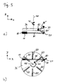
- a third embodiment of the present invention is displayed in figure 5.
- a side view of this embodiment shown in figure 5a shows a laser source 11 having a first cavity end mirror 10 as a back facet emitting a beam 80 towards a grating 20.
- the beam 80 is redirected as a beam 80' having a selected wavelength range towards a redirection mirror 60 which is mounted on a rotating wheel having a rotation axis 40.
- the optical path, which the beam takes has a three dimensional curvature, which depends on the current rotation angle of the wheel 36.
- the optical path length of the cavity is a function of the current rotation angle of the wheel 36.
- a set of six redirection mirrors 60 is arranged equidistantly on wheel 36.
- a retro-reflector is used in order to compensate maladjustments of the redirection mirrors 60.
- a fourth embodiment of the present invention is shown in figure 6.
- a laser source 11 having a first cavity end mirror 10 as a back facet emits a beam 80' through a collimating lens 12 towards a grating 20 redirecting said beam towards a second cavity end mirror 30.
- the cavity obeys a Littmann-condition in that a pivot point 100 exists corresponding to intersecting lines 90, 91, 92 extended from the first and second cavity end mirrors 10, 30 and the grating 20.
- Both the grating 20 and a second cavity end mirror 30 are mounted on a support, which rotates about an axis 40.
- the axis coincides with pivot point 100.
- a distance between the second cavity end mirror 30 and the grating 20 is held constant throughout the rotation movement.
- a tuning of the cavity wavelength is provided by a variation in optical path length due to an inclination of the grating 20 with respect to the direction of beam 80'.
- a retro-reflector 13 preserves a laser-condition in case but no grating 20 intersects with beam 80'.
- a particular advantage of the present embodiment arises from the fact that no mechanical efforts have to be undertaken in order to circumvent the obstruction of grating 20 with second cavity end mirror 30.
- a further example of a tunable cavity is displayed in figure 7.
- a laser source 11 emits a beam 80' towards a grating 20 mounted on a wheel 36.
- the grating 20 extends around the outer surface of wheel 36 having a constantly varying grating constant 141, 142, 143.
- the wheel 36 rotates around the rotation axis 40 thus varying the grating constant that is active in redirecting the beam 80 towards the second cavity end mirror 30.
- another control unit can adjust the position of the second cavity end mirror 30.
- a drive-rotating wheel 36 as well as a drive adjusting cavity end mirror 30 are connected to said control unit.
- an active grating constant can be determined by said control unit and the current angle of the cavity end mirror 30 with respect to pivot point 100 can be adjusted in order to tune the wavelength of the cavity.
- FIG. 9 A further example concerning the case of gratings 20, 20' rotating about an axis 40 is displayed in figure 9.
- An octagon 37 comprising eight gratings 20 is supplied with a beam 80' emitted from a laser source 11.
- the beam 80 is redirected towards a second cavity end mirror 30, which may be shifted in accordance with the actual rotation angle of the grating 20.
- the adjustment is carried out to compensate the change of line 91 towards a line 91a defining an extension of grating 20 towards a pivot point 100. Since due to the rotation movement 41 of the octagon the pivot point 100 starts to move towards another position 100' an extension line 92 of the second cavity end mirror 30 has to be shifted to a line 92a running through the new pivot point 100'.
- the optical path length of beam 80', 80 varies, while a Littmann-condition is still preserved until the next grating 20' becomes the active grating 20, which receives beam 80' from the laser source 11.
Landscapes
- Physics & Mathematics (AREA)
- Electromagnetism (AREA)
- Engineering & Computer Science (AREA)
- Plasma & Fusion (AREA)
- Optics & Photonics (AREA)
- Lasers (AREA)
- Semiconductor Lasers (AREA)
- Mechanical Light Control Or Optical Switches (AREA)
Claims (8)
- Resonator mit abstimmbarer Wellenlänge, der Folgendes umfasst:einen ersten Endspiegel (10) des Resonators, wobei der Endspiegel geeignet ist, einen einfallenden Strahl (80) einer elektromagnetischen Strahlung zumindest teilweise in Richtung eines zweiten Endspiegels (30) des Resonators zu reflektieren,wobei der zweite Endspiegel (30) des Resonators geeignet ist, einen einfallenden Strahl (80) einer elektromagnetischen Strahlung zumindest teilweise wieder in Richtung des ersten Endspiegels (10) des Resonators zu reflektieren, wobei die beiden Endspiegel (10, 30) des Resonators die Bildung von Resonanzmoden der elektromagnetischen Strahlung innerhalb des Resonators bewirken und die Länge eines optischen Pfades des Strahls (80) innerhalb des Resonators durch den ersten (10) und den zweiten Endspiegel (30) des Resonators definiert wird,ein Gitter (20), das im Strahlengang des durch den ersten Endspiegel (10) des Resonators reflektierten Strahls (80) angeordnet ist, wobei das Gitter (20) zum Abstimmen der Wellenlänge des Strahls (80) geeignet ist,dadurch gekennzeichnet, dass der zweite Endspiegel (30) des Resonators um einen Winkel von mindestens 360 Grad drehbar um eine Achse (40) angeordnet ist, um eine kontinuierliche Bewegung (41) des zweiten Endspiegels (30) des Resonators entlang einer Kreisbahn in Bezug auf das Gitter (20) zu erzeugen,wobei die Kreisbahn des zweiten Endspiegels (30) des Resonators mindestens einen Teil (32) umfasst, der so angeordnet ist, dass er den durch das Gitter (20) umgelenkten Strahl (80) schneidet.
- Resonator nach Anspruch 1, der femer eine Laserquelle umfasst, die wiederum
ein Verstärkungsmedium zum Emittieren des Strahls (80) einer elektromagnetischen Strahlung durch eine Vorderfläche entlang des optischen Pfades in Richtung des Gitters (20), und
den ersten Endspiegel (10) des Resonators als Rückflächenspiegel umfasst. - Resonator nach Anspruch 1 oder einem der vorangehenden Ansprüche, bei dem der erste (10) und der zweite Endspiegel (30) des Resonators und das Gitter (20) als Littmann-Resonator mit einem Drehpunkt (100) angeordnet sind, wobei sich der Drehpunkt (100) an einer im Wesentlichen innerhalb der Rotationsachse (40) des zweiten Endspiegels (30) des Resonators gelegenen Stelle befindet.
- Resonator nach Anspruch 1 oder einem der vorangehenden Ansprüche, bei dem die Rotationsachse (40) des zweiten Endspiegels (30) des Resonators im Wesentlichen rechtwinklig zu einer durch den ersten (10) und den zweiten Endspiegel (30) des Resonators und das Gitter (20) definierten Ebene angeordnet ist.
- Resonator mit abstimmbarer Wellenlänge, der Folgendes umfasst:einen ersten Endspiegel des Resonators, wobei der Endspiegel geeignet ist, einen einfallenden Strahl einer elektromagnetischen Strahlung zumindest teilweise in Richtung des ersten Endspiegels des Resonators zu reflektieren,einen zweiten Endspiegel des Resonators, wobei der Endspiegel geeignet ist, einen einfallenden Strahl einer elektromagnetischen Strahlung zumindest teilweise zum ersten Endspiegel des Resonators zu reflektieren, wobei die beiden Endspiegel des Resonators die Bildung von Resonanzmoden der elektromagnetischen Strahlung innerhalb des Resonators bewirken und die Länge eines optischen Pfades des Strahls innerhalb des Resonators durch den ersten und den zweiten Endspiegel des Resonators definiert wird,ein Gitter zum Umlenken des optischen Pfades des durch den ersten Endspiegel des Resonators reflektierten Strahls in Richtung des zweiten Endspiegels des Resonators, wobei das Gitter zum Abstimmen der Wellenlänge des Strahls durch Beugung geeignet ist,dadurch gekennzeichnet, dass ein Umlenkspiegel zum Umlenken des optischen Pfades des Strahls enthalten ist, der vom Gitter in Richtung des zweiten Endspiegels des Resonators umgelenkt wird,wobei der Umlenkspiegel so angeordnet ist, dass er entlang einer Kreisbahn um einen Winkel von mindestens 360 Grad um eine Achse gedreht werden kann, um eine kontinuierliche Bewegung in Bezug auf das Gitter und den zweiten Endspiegel des Resonators zu erzeugen,wobei die Kreisbahn des Umlenkspiegels mindestens einen Teil umfasst, der so angeordnet ist, dass er den Strahl schneidet, wenn dieser durch das Gitter umgelenkt wird.
- Resonator mit abstimmbarer Wellenlänge, der Folgendes umfasst:einen ersten Endspiegel des Resonators, wobei der Endspiegel geeignet ist, einen einfallenden Strahl einer elektromagnetischen Strahlung zumindest teilweise in Richtung eines zweiten Endspiegels des Resonators zu reflektieren,wobei der zweite Endspiegel des Resonators geeignet ist, einen einfallenden Strahl einer elektromagnetischen Strahlung zumindest teilweise in Richtung des ersten Endspiegels des Resonators zu reflektieren, wobei die beiden Endspiegel des Resonators die Bildung von Resonanzmoden der elektromagnetischen Strahlung innerhalb des Resonators bewirken und die Länge eines optischen Pfades des Strahls innerhalb des Resonators durch den ersten und den zweiten Endspiegel des Resonators definiert wird,ein Gitter, das im Strahlengang des durch den ersten Endspiegel des Resonators reflektierten Strahls angeordnet ist, wobei das Gitter zum Abstimmen der Wellenlänge des Strahls dient,dadurch gekennzeichnet, dass sowohl der zweite Endspiegel des Resonators als auch das Gitter so angeordnet sind, dass sie auf einer Kreisbahn um einen Winkel von mindestens 360 Grad um eine Achse gedreht werden können, um eine kontinuierliche Bewegung in Bezug auf das Gitter zu erzeugen,wobei die Kreisbahn des Gitters mindestens einen Teil umfasst, der so angeordnet ist, dass er den durch den ersten Endspiegel des Resonators reflektierten Strahl schneidet.
- Resonator nach Anspruch 6, der femer eine Laserquelle umfasst, die wiederum:ein Verstärkungsmedium zum Emittieren des Strahls (80) einer elektromagnetischen Strahlung durch eine Vorderfläche entlang des optischen Pfades in Richtung des Gitters (20), undden ersten Endspiegel (10) des Resonators als Rückflächenspiegel umfasst.
- Verfahren, das die folgenden Schritte umfasst:Reflektieren eines einfallenden Strahls (80) einer elektromagnetischen Strahlung von einem ersten Endspiegel (10) des Resonators zumindest teilweise in Richtung eines zweiten Endspiegels (30) des Resonators,Reflektieren eines einfallenden Strahls (80) einer elektromagnetischen Strahlung von dem mindestens einen zweiten Endspiegels (30) des Resonators zumindest teilweise zurück in Richtung des ersten Endspiegels (10) des Resonators, wobei die beiden Endspiegel (10, 30) des Resonators die Bildung von Resonanzmoden der elektromagnetischen Strahlung innerhalb des Resonators bewirken und die Länge eines optischen Pfades des Strahls (80) innerhalb des Resonators durch den ersten (10) und den zweiten Endspiegel (30) des Resonators definiert wird,Abstimmen der Wellenlänge des Strahls (80) mittels eines Gitters (20), das innerhalb des optischen Pfades des durch den ersten Endspiegel (10) des Resonators reflektierten Strahls (80) angeordnet ist,gekennzeichnet durchDrehen des mindestens einen zweiten Endspiegels (30) des Resonators um einen Winkel von mindestens 360 Grad um eine Achse (40), um eine kontinuierliche Bewegung (41) des zweiten Endspiegels (30) des Resonators auf einer Kreisbahn in Bezug auf das Gitter (20) zu erzeugen, wobei die Kreisbahn des zweiten Endspiegels (30) des Resonators mindestens einen Teil (32) umfasst, der so angeordnet ist, dass er den durch das Gitter (20) umgelenkten Strahl (80) schneidet.
Applications Claiming Priority (1)
| Application Number | Priority Date | Filing Date | Title |
|---|---|---|---|
| PCT/EP2002/010712 WO2004030166A1 (en) | 2002-09-25 | 2002-09-25 | Wavelength tunable cavity with rotational movement |
Publications (2)
| Publication Number | Publication Date |
|---|---|
| EP1547209A1 EP1547209A1 (de) | 2005-06-29 |
| EP1547209B1 true EP1547209B1 (de) | 2007-01-10 |
Family
ID=32039074
Family Applications (1)
| Application Number | Title | Priority Date | Filing Date |
|---|---|---|---|
| EP02779412A Expired - Lifetime EP1547209B1 (de) | 2002-09-25 | 2002-09-25 | Abstimmbarer laserresonator mit rotierendem element |
Country Status (6)
| Country | Link |
|---|---|
| US (1) | US7463668B2 (de) |
| EP (1) | EP1547209B1 (de) |
| JP (1) | JP2006500776A (de) |
| AU (1) | AU2002342751A1 (de) |
| DE (1) | DE60217558T2 (de) |
| WO (1) | WO2004030166A1 (de) |
Families Citing this family (5)
| Publication number | Priority date | Publication date | Assignee | Title |
|---|---|---|---|---|
| EP2034570A1 (de) * | 2003-07-03 | 2009-03-11 | PD-LD, Inc. | Verwendung von Volumen-Bragg-Gittern zur Festlegung von Laseremissionseigenschaften |
| WO2011000153A1 (zh) * | 2009-06-30 | 2011-01-06 | 山东远普光学股份有限公司 | 连续无跳模可调谐光栅外腔半导体激光器 |
| EP2287980A1 (de) * | 2009-08-21 | 2011-02-23 | Karlsruher Institut für Technologie | Durchstimmbare Laserlichtquelle auf Basis variabler optischer Pulsanregung und Verfahren zum Betreiben derselben |
| NL2022286B1 (en) * | 2018-09-19 | 2020-05-07 | Illumina Inc | Structured illumination of a sample |
| US10901202B2 (en) | 2018-09-19 | 2021-01-26 | Illumina, Inc. | Structured illumination of a sample |
Family Cites Families (5)
| Publication number | Priority date | Publication date | Assignee | Title |
|---|---|---|---|---|
| US4601036A (en) * | 1982-09-30 | 1986-07-15 | Honeywell Inc. | Rapidly tunable laser |
| US4862468A (en) * | 1987-04-27 | 1989-08-29 | Hughes Aircraft Company | Rapidly switchable line selector for pulsed lasers |
| US4868834A (en) * | 1988-09-14 | 1989-09-19 | The United States Of America As Represented By The Secretary Of The Army | System for rapidly tuning a low pressure pulsed laser |
| US5283795A (en) * | 1992-04-21 | 1994-02-01 | Hughes Aircraft Company | Diffraction grating driven linear frequency chirped laser |
| US5537432A (en) * | 1993-01-07 | 1996-07-16 | Sdl, Inc. | Wavelength-stabilized, high power semiconductor laser |
-
2002
- 2002-09-25 EP EP02779412A patent/EP1547209B1/de not_active Expired - Lifetime
- 2002-09-25 WO PCT/EP2002/010712 patent/WO2004030166A1/en not_active Ceased
- 2002-09-25 DE DE60217558T patent/DE60217558T2/de not_active Expired - Fee Related
- 2002-09-25 US US10/529,437 patent/US7463668B2/en not_active Expired - Fee Related
- 2002-09-25 JP JP2004538787A patent/JP2006500776A/ja active Pending
- 2002-09-25 AU AU2002342751A patent/AU2002342751A1/en not_active Abandoned
Also Published As
| Publication number | Publication date |
|---|---|
| DE60217558T2 (de) | 2007-05-03 |
| US20060274810A1 (en) | 2006-12-07 |
| JP2006500776A (ja) | 2006-01-05 |
| AU2002342751A1 (en) | 2004-04-19 |
| DE60217558D1 (de) | 2007-02-22 |
| US7463668B2 (en) | 2008-12-09 |
| WO2004030166A1 (en) | 2004-04-08 |
| EP1547209A1 (de) | 2005-06-29 |
Similar Documents
| Publication | Publication Date | Title |
|---|---|---|
| EP1459111B1 (de) | Externer resonator mit retro-reflektierender vorrichtung insbesondere für abstimmbare laser | |
| EP2377212B1 (de) | Frequenzabstimmbare laservorrichtung | |
| CA2324182C (en) | Method and device for optically crossconnecting optical signals using tilting mirror mems with drift monitoring feature | |
| US4656641A (en) | Laser cavity optical system for stabilizing the beam from a phase locked multi-emitter broad emitter laser | |
| US6188500B1 (en) | Method for generating multiple scan lines in a thin scanner | |
| US6301274B1 (en) | Tunable external cavity laser | |
| US20220236383A1 (en) | Micro-electro-mechanical system (mems) micro-mirror array (mma) steered active situational awareness sensor | |
| US20010053013A1 (en) | Scanner with synchronously switched optics | |
| US7463668B2 (en) | Wavelength tunable cavity with rotational movement | |
| US5754328A (en) | Mid-objective laser scanner | |
| US6118471A (en) | Beam diameter control method and device | |
| US20220260685A1 (en) | Conic micro-electro-mechanical system (mems) micro-mirror array (mma) steered active situational awareness sensor | |
| JP2003161907A (ja) | レーザビーム径可変装置 | |
| US4251125A (en) | Scanning optical system including an afocal system | |
| JP3358420B2 (ja) | 光学走査装置 | |
| EP0775928B1 (de) | Optischer Scanner | |
| US5650871A (en) | Single element optics for passive facet tracking | |
| US5337182A (en) | Optical Scanner | |
| JPH10177147A (ja) | 光学装置及び光学装置の走査方法 | |
| JP2004500698A (ja) | リットマン配置の外部共振器を備えたダイオードレーザーの調節可能なシステム | |
| JPH1048558A (ja) | レーザ走査光学ユニット | |
| US5559627A (en) | Optics for passive facet tracking | |
| JPH03287220A (ja) | 光走査装置 | |
| JPS62278521A (ja) | 光ビ−ム走査装置 | |
| US5486945A (en) | Optics for passive facet tracking |
Legal Events
| Date | Code | Title | Description |
|---|---|---|---|
| PUAI | Public reference made under article 153(3) epc to a published international application that has entered the european phase |
Free format text: ORIGINAL CODE: 0009012 |
|
| 17P | Request for examination filed |
Effective date: 20050425 |
|
| AK | Designated contracting states |
Kind code of ref document: A1 Designated state(s): AT BE BG CH CY CZ DE DK EE ES FI FR GB GR IE IT LI LU MC NL PT SE SK TR |
|
| AX | Request for extension of the european patent |
Extension state: AL LT LV MK RO SI |
|
| DAX | Request for extension of the european patent (deleted) | ||
| RBV | Designated contracting states (corrected) |
Designated state(s): DE FR GB |
|
| RIN1 | Information on inventor provided before grant (corrected) |
Inventor name: HABERLAND, UDO Inventor name: STEFFENS, WOLF Inventor name: SCHMIDT, ANDREAS Inventor name: HEITKAMP, JENS |
|
| GRAP | Despatch of communication of intention to grant a patent |
Free format text: ORIGINAL CODE: EPIDOSNIGR1 |
|
| RTI1 | Title (correction) |
Free format text: WAVELENGTH TUNABLE CAVITY WITH ROTATIONAL MOVEMENT |
|
| GRAS | Grant fee paid |
Free format text: ORIGINAL CODE: EPIDOSNIGR3 |
|
| GRAA | (expected) grant |
Free format text: ORIGINAL CODE: 0009210 |
|
| AK | Designated contracting states |
Kind code of ref document: B1 Designated state(s): DE FR GB |
|
| REG | Reference to a national code |
Ref country code: GB Ref legal event code: FG4D |
|
| RAP2 | Party data changed (patent owner data changed or rights of a patent transferred) |
Owner name: AGILENT TECHNOLOGIES, INC. |
|
| REF | Corresponds to: |
Ref document number: 60217558 Country of ref document: DE Date of ref document: 20070222 Kind code of ref document: P |
|
| ET | Fr: translation filed | ||
| PLBE | No opposition filed within time limit |
Free format text: ORIGINAL CODE: 0009261 |
|
| STAA | Information on the status of an ep patent application or granted ep patent |
Free format text: STATUS: NO OPPOSITION FILED WITHIN TIME LIMIT |
|
| 26N | No opposition filed |
Effective date: 20071011 |
|
| PGFP | Annual fee paid to national office [announced via postgrant information from national office to epo] |
Ref country code: GB Payment date: 20070926 Year of fee payment: 6 |
|
| PGFP | Annual fee paid to national office [announced via postgrant information from national office to epo] |
Ref country code: FR Payment date: 20070917 Year of fee payment: 6 |
|
| PGFP | Annual fee paid to national office [announced via postgrant information from national office to epo] |
Ref country code: DE Payment date: 20081002 Year of fee payment: 7 |
|
| GBPC | Gb: european patent ceased through non-payment of renewal fee |
Effective date: 20080925 |
|
| REG | Reference to a national code |
Ref country code: FR Ref legal event code: ST Effective date: 20090529 |
|
| PG25 | Lapsed in a contracting state [announced via postgrant information from national office to epo] |
Ref country code: FR Free format text: LAPSE BECAUSE OF NON-PAYMENT OF DUE FEES Effective date: 20080930 |
|
| PG25 | Lapsed in a contracting state [announced via postgrant information from national office to epo] |
Ref country code: GB Free format text: LAPSE BECAUSE OF NON-PAYMENT OF DUE FEES Effective date: 20080925 |
|
| PG25 | Lapsed in a contracting state [announced via postgrant information from national office to epo] |
Ref country code: DE Free format text: LAPSE BECAUSE OF NON-PAYMENT OF DUE FEES Effective date: 20100401 |