EP1546644B1 - Reorientation of a stylus pen - Google Patents
Reorientation of a stylus pen Download PDFInfo
- Publication number
- EP1546644B1 EP1546644B1 EP03761714.9A EP03761714A EP1546644B1 EP 1546644 B1 EP1546644 B1 EP 1546644B1 EP 03761714 A EP03761714 A EP 03761714A EP 1546644 B1 EP1546644 B1 EP 1546644B1
- Authority
- EP
- European Patent Office
- Prior art keywords
- stylus
- engagement
- repositioning
- relative
- measurement device
- Prior art date
- Legal status (The legal status is an assumption and is not a legal conclusion. Google has not performed a legal analysis and makes no representation as to the accuracy of the status listed.)
- Expired - Lifetime
Links
Images


Classifications
-
- G—PHYSICS
- G01—MEASURING; TESTING
- G01B—MEASURING LENGTH, THICKNESS OR SIMILAR LINEAR DIMENSIONS; MEASURING ANGLES; MEASURING AREAS; MEASURING IRREGULARITIES OF SURFACES OR CONTOURS
- G01B5/00—Measuring arrangements characterised by the use of mechanical techniques
- G01B5/004—Measuring arrangements characterised by the use of mechanical techniques for measuring coordinates of points
- G01B5/008—Measuring arrangements characterised by the use of mechanical techniques for measuring coordinates of points using coordinate measuring machines
- G01B5/012—Contact-making feeler heads therefor
-
- G—PHYSICS
- G01—MEASURING; TESTING
- G01B—MEASURING LENGTH, THICKNESS OR SIMILAR LINEAR DIMENSIONS; MEASURING ANGLES; MEASURING AREAS; MEASURING IRREGULARITIES OF SURFACES OR CONTOURS
- G01B7/00—Measuring arrangements characterised by the use of electric or magnetic techniques
- G01B7/004—Measuring arrangements characterised by the use of electric or magnetic techniques for measuring coordinates of points
- G01B7/008—Measuring arrangements characterised by the use of electric or magnetic techniques for measuring coordinates of points using coordinate measuring machines
- G01B7/012—Contact-making feeler heads therefor
-
- G—PHYSICS
- G01—MEASURING; TESTING
- G01B—MEASURING LENGTH, THICKNESS OR SIMILAR LINEAR DIMENSIONS; MEASURING ANGLES; MEASURING AREAS; MEASURING IRREGULARITIES OF SURFACES OR CONTOURS
- G01B21/00—Measuring arrangements or details thereof, where the measuring technique is not covered by the other groups of this subclass, unspecified or not relevant
- G01B21/02—Measuring arrangements or details thereof, where the measuring technique is not covered by the other groups of this subclass, unspecified or not relevant for measuring length, width, or thickness
- G01B21/04—Measuring arrangements or details thereof, where the measuring technique is not covered by the other groups of this subclass, unspecified or not relevant for measuring length, width, or thickness by measuring coordinates of points
- G01B21/042—Calibration or calibration artifacts
Definitions
- the present invention relates to the orientation of a stylus of a measurement type probe e.g. as used on a coordinate positioning machine, brought about by the movement of part of the probe whilst inhibiting movement of the stylus part.
- the stylus may need to be repositioned. There are a number of ways in which this can be done. Possibly a different stylus can be used for each of the surface and bore inspections, or as is desirable the stylus can be repositioned into a new position. Repositioning can be effected by motors within the probe. Alternatively, repositioning can be effected by restraining some part of the stylus and moving the probe support to reorientate the stylus. A device of this latter type is disclosed in US Patent No. 5,848,477 .
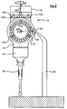
- Fig 1 shows a typical coordinate measurement machine 2 (CMM) capable of moving a probe 10 in X,Y and Z axes.
- CMM coordinate measurement machine 2
- the probe 10 together with a stylus 30 held in stylus holder 12 is moved towards the surface of the workpiece until a stylus tip 34 touches the workpiece.
- the probe 10 produces a signal to stop the movement of the probe and to record the coordinate position of the stylus tip. From this information dimensions of the workpiece can be determined. Desirably all dimensions of the features of the workpiece need to be determined in one operation without moving the workpiece. This can be achieved as described above, either by using different styli, or reorientating the stylus.
- Fig 1 the probe support is illustrated in a second position 8'.
- Stylus 30 is held by a stylus repositioning device 50 whilst the quill is moved from 8 to 8'.
- This movement will involve adjustments to the probe support in two or possibly three axes.
- Further reorientation of the stylus holder 12 will, in the example illustrated in Fig 1 , enable the dimensions of the three bores in the workpiece 5 to be inspected.
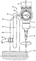
- One type of measurement probe arrangement which has a repositionable stylus is illustrated in more detail in Fig 2 .
- the Figure shows a probe head 14 which has the features described in US 4 571 847 .
- this head supports movably a probe 10.
- Stylus 30 is connected to the probe 10, and both probe and stylus are repositionable to a number of pre-selected repeatable positions relative to the quill 8.
- Probe support 12 may be rotated about axis A and has three sets of roller pairs 120, each pair being engageable with opposite sides of one of a ring of balls 122. Thus a total of six contact points are made and rotational increments of the probe support 12 equal to the angular ball spacing are possible (15 degrees in this case).
- a similar arrangement is provided for rotation of the probe support about axis B.
- the balls and rollers are biased into engagement by springs so that their relative position is maintained in use.
- the spring bias can be overcome readily for repositioning.
- the stylus 30 (together with the probe 10 in this instance) can be repositioned by obstructing the probe support 12 whilst moving the quill 8. Obstruction of the support 12 is brought about in this example by use of a stylus repositioning device 50.
- the device 50 is held stationary and has a ball 52 engageable with a receptacle 54 in the probe support 12.
- the ball 52 and receptacle 54 form first and second mutually engageable portions of an engagement.
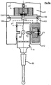
- a similar head 14,probe 10 and stylus 12 are shown in Figure 3 .
- the head is modified such that the receptacle is replaced with a stalk 56 and ball 58.
- a different stylus repositioning device 503 is shown.
- the repositioning device 503 holds the ball 58 whilst movement of the quill 8 in an arc R takes place. This movement is centred about the ball 58.
- the device 503 comprises a conduit 48 within a body 60. At one end of the conduit is a lip 62 which forms a datum surface for holding the ball 58. Ball 58 and lip 62 form first and second mutually engageable portions of an engagement.
- a vacuum which is provided by a vacuum tube 64.
- the body 60 is mounted to a base 66 which can be fixed to the bed 4 of the coordinate measurement machine 2.
- the ball 58 is moved into contact with the lip 62 and a vacuum is generated within the conduit 48. This vacuum holds the ball 58 against the lip 62 whilst the probe support 12 is repositioned about axis A and/or B.
- Fig 3a shows a variant of the probe assembly shown in Fig 3 .
- the roller pairs 120 and balls 122 are caused to separate by the action of solenoids 74 acting in the direction of arrows C.
- Parting of the ball and roller sets provides less resistance to reorientation.
- Activation of the solenoids can be via an instruction from the CMM, both solenoids 74 can be operated together or the solenoids can be operated singly.
- the solenoids are energised via an electrical path P which runs from a supply at the quill 8, through both solenoids and through the repositioning device 503 or 50 via ball 58.
- the act of contacting the repositioning device energises the solenoids and separates the balls and rollers.
- Other separation systems are possible e.g. mechanical or vacuum types.
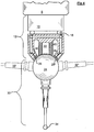
- Figures 4 and 5 show a variant of the head 14 shown in Figures 2 and 3 .
- the stylus 30 is movable about a stylus holder 12' and the probe 10 is fixed in relation to the quill 8.
- Figure 4 shows a probe 10 which produces a signal to stop the coordinate measurement machine when stylus tip 34 touches a surface. Also shown is a movable stylus 30 which may swing in any direction by virtue of a universal joint formed between cup-shaped bearing surfaces 25 and ball 24.
- the stylus holder 12' is normally held in place but is free, when released, to swing in a part-spherical manner to bring the stylus into positions within the limits shown by the feint outlines 30' and 30" (i.e. greater than hemispherical movement).
- the probe assembly includes a kinematic joint 18 connecting the probe 10 and stylus holder 12'.
- ball 24 is held statically in place in contact with bearing surfaces 25 by the attractive force of a magnet 22.
- An electromagnet 20 is shown also which may provide additional attraction to hold the ball 24 in place.
- the ball 24 may be made of ferrous material, or a hollow ceramic body filled with ferrous fluent material.
- Bearing surfaces 25 may be three pads of ceramic material.
- the magnetic attraction between ball 24 and magnet 22 may be reduced by inducing an opposite field in electromagnet 20.
- the electromagnet may be pulsed or the current may be alternated to provide vibrations between the support 12 and the ball 24. These vibrations will reduce the friction in the universal joint.
- An optional air supply 38 is shown for feeding jets 36. These air jets 36 provide a low friction universal joint, when operated. Where an air supply is provided on the machine this may be used to supply pressurised air via conduit 38 to air jets 36 whilst movement of the universal joint takes place. This air supply will cause a fluid film to form between the surface of the ball 24 and the bearing surfaces 25 and will thereby reduce the friction between the two. The fluid film may replace or augment the electromagnetic friction reducing effects mentioned above.
- the current in the electromagnet 20 may be switched off or reversed, and/or the air supply discontinued.
- the stylus 30 will thus be repositioned and ready for use.
- FIG. 5 shows a similar probe assembly to that shown in Figure 4 .
- electromagnet 20 and magnet 22 are replaced by a vacuum chamber 42.
- Vacuum is induced via a conduit 44.
- a part-spherical bearing surface 46 is provided.
- a vacuum is held in the chamber 42, to hold the stylus 30 in place, in static relation to the stylus support 12'.
- the pressure within the chamber 42 is increased so as to reduce the holding force on the ball 24. Once reorientation has taken place the pressure in the chamber 42 is reduced once more.
- an electromagnet and/or air bearings may be used to reduce friction, as described above.
- Ball 24 need not be of a magnetic/magnetisable material if a vacuum is used solely.
- Figures 6 and 7 shows two possible modifications of the styli 30 illustrated in Figures 4 and 5 which may be used in order that these styli may be repositionable using the quill 8 as a driving force.
- a receptacle 54' similar to the receptacle 54 illustrated in Figure 2 is used.
- a stylus repositioning device 50 is used.
- the repositioning technique is as described with reference to Figure 2 .
- the path R again has a radius r.
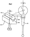
- Figure 7 shows another possible modification.
- a stalk 160 is attached to the stylus 30 and a cylinder 164 is attached to the stalk.
- the cylinder 164 is engageable with a rotatable stylus repositioning device 507.
- the device has a vee slot 66 for accepting the cylinder and for holding it by means of magnetism. Repositioning of the stylus is performed by moving the quill 8 as described above in a path R which has a radius r. Movement of the quill about a centre of rotation coincident with the centre of rotation B' of the device 507 allows further repositioning of the stylus 30 about axis B.
- the description refers to a vacuum.
- this word encompasses any fluid pressure which is lower than ambient or a complete vacuum.
- Figs 4 , 5 , 6 and 7 show a ball and cup type universal joint.
- any universal joint having a convexity and an element be to received around the convexity, or a concavity and an element to be received into the concavity will suffice as an alternative.
- a large ball (the convexity) nestable within three smaller spaced balls, or a cup (a concavity) as one piece of the joint and three balls in fixed relation to be received into the cup.
- An array of contact points arranged to provide an effective concave on convex spherical pattern could be used on an equivalent concave or convex spherical surface.
- Balls 122 and rollers 120 have been shown in Figs 2 , 3 and 3a . Any kinematic arrangement could be used instead of this arrangement, in order to provide a plurality of repeatable positions, e.g. an array of radially extending vee slots and three mating balls.
- coordinate measurement machine as used herein is intended to encompass any machine capable of determining co-ordinates, cartesian or otherwise, e.g. a machine tool or a robotic arm having position determination.
Landscapes
- Physics & Mathematics (AREA)
- General Physics & Mathematics (AREA)
- Length Measuring Devices With Unspecified Measuring Means (AREA)
- A Measuring Device Byusing Mechanical Method (AREA)
Applications Claiming Priority (3)
| Application Number | Priority Date | Filing Date | Title |
|---|---|---|---|
| GBGB0215152.0A GB0215152D0 (en) | 2002-07-01 | 2002-07-01 | Probe or stylus orientation |
| GB0215152 | 2002-07-01 | ||
| PCT/GB2003/002810 WO2004003466A2 (en) | 2002-07-01 | 2003-07-01 | Probe or stylus orientation |
Publications (2)
| Publication Number | Publication Date |
|---|---|
| EP1546644A2 EP1546644A2 (en) | 2005-06-29 |
| EP1546644B1 true EP1546644B1 (en) | 2017-12-06 |
Family
ID=9939603
Family Applications (1)
| Application Number | Title | Priority Date | Filing Date |
|---|---|---|---|
| EP03761714.9A Expired - Lifetime EP1546644B1 (en) | 2002-07-01 | 2003-07-01 | Reorientation of a stylus pen |
Country Status (7)
| Country | Link |
|---|---|
| US (2) | US7100297B2 (enExample) |
| EP (1) | EP1546644B1 (enExample) |
| JP (1) | JP4361016B2 (enExample) |
| CN (1) | CN1695036B (enExample) |
| AU (1) | AU2003251143A1 (enExample) |
| GB (1) | GB0215152D0 (enExample) |
| WO (1) | WO2004003466A2 (enExample) |
Families Citing this family (42)
| Publication number | Priority date | Publication date | Assignee | Title |
|---|---|---|---|---|
| GB0019200D0 (en) * | 2000-08-05 | 2000-09-27 | Renishaw Plc | Bearing arrangement |
| EP1617172B1 (fr) * | 2004-07-16 | 2007-12-26 | Tesa SA | Palpeur orientable |
| GB0501690D0 (en) * | 2005-01-27 | 2005-03-02 | Renishaw Plc | Articulating device |
| DE102005032749A1 (de) * | 2005-07-13 | 2007-01-18 | Carl Zeiss Industrielle Messtechnik Gmbh | Verfahren zum Antasten eines Werkstücks mit einem Koordinatenmessgerät und Koordinatenmessgeräte |
| GB0605796D0 (en) * | 2006-03-23 | 2006-05-03 | Renishaw Plc | Apparatus and method of measuring workpieces |
| GB0617344D0 (en) * | 2006-09-05 | 2006-10-11 | Renishaw Plc | Surface sensing device |
| ATE459856T1 (de) * | 2006-09-05 | 2010-03-15 | Renishaw Plc | Oberflächenmesseinrichtung |
| EP1978328B1 (en) * | 2007-04-03 | 2015-02-18 | Hexagon Metrology AB | Oscillating scanning probe with constant contact force |
| DE102007022326B4 (de) | 2007-05-08 | 2022-07-07 | Carl Zeiss Industrielle Messtechnik Gmbh | Koordinatenmessgerät zum Bestimmen von Raumkoordinaten an einem Messobjekt sowie Dreh-Schwenk-Mechanismus für ein solches Koordinatenmessgerät |
| DE202007012868U1 (de) * | 2007-09-14 | 2007-12-06 | The Gleason Works Corp. | Schlittenanordnung für eine Werkzeugmaschine |
| US8250772B2 (en) * | 2008-02-07 | 2012-08-28 | Eaton Homer L | Spatial measurement and robotic arm device |
| US7587834B2 (en) * | 2008-02-07 | 2009-09-15 | Eaton Homer L | Motorized coordinate measuring device |
| GB0804114D0 (en) * | 2008-03-05 | 2008-04-09 | Renishaw Plc | Surface sensing device |
| US8453337B2 (en) * | 2009-06-02 | 2013-06-04 | James Richard Lacy | System and method for workpiece coordinate measurements |
| DE102010006505B4 (de) | 2010-01-28 | 2013-09-19 | Carl Zeiss Industrielle Messtechnik Gmbh | Koordinatenmessgerät mit passivem Dreh-Schwenk-Mechanismus |
| JP5410317B2 (ja) * | 2010-02-05 | 2014-02-05 | 株式会社ミツトヨ | 三次元測定機 |
| EP2381212B1 (en) * | 2010-04-26 | 2018-04-25 | Tesa Sa | Coordinate measuring system for rotationally symmetric workpieces |
| EP2384851B1 (en) * | 2010-05-03 | 2018-01-03 | Tesa Sa | Coordinate Measuring System with rotatory adapter |
| EP2386845B1 (en) * | 2010-05-14 | 2024-03-13 | Nordson Corporation | Apparatus and method for testing of bonds of a semiconductor assembly |
| EP2386846A1 (en) * | 2010-05-14 | 2011-11-16 | Nordson Corporation | System and method for testing of bonds of a semiconductor assembly |
| GB201013938D0 (en) * | 2010-08-20 | 2010-10-06 | Renishaw Plc | Method for recalibrating coordinate positioning apparatus |
| EP3926294B1 (de) * | 2010-09-10 | 2024-02-21 | Carl Zeiss Industrielle Messtechnik GmbH | Taststift-anordnung |
| DE102011100467B3 (de) * | 2011-05-02 | 2012-07-05 | Carl Zeiss Industrielle Messtechnik Gmbh | Messkopf für ein Koordinatenmessgerät zum Bestimmen von Raumkoordinaten an einem Messobjekt |
| EP2839241B1 (en) | 2012-04-18 | 2018-08-08 | Renishaw PLC | Method of finding a feature of an object using a machine tool and corresponding machine tool apparatus |
| CN104969028B (zh) * | 2012-04-18 | 2018-06-01 | 瑞尼斯豪公司 | 在机床上进行模拟测量扫描的方法和对应的机床设备 |
| EP3239653B1 (en) | 2012-04-18 | 2018-11-21 | Renishaw plc | Method of measurement on a machine tool and corresponding machine tool |
| JP5982194B2 (ja) * | 2012-06-26 | 2016-08-31 | 株式会社アルバック | 起点座標補正方法 |
| KR101459443B1 (ko) | 2012-12-14 | 2014-11-07 | 현대자동차 주식회사 | 센서 위치 제어장치 및 그 제어방법 |
| US9696517B2 (en) * | 2014-03-19 | 2017-07-04 | Jefferson Science Associates, Llc | Insertion device and method for accurate and repeatable target insertion |
| US10401162B2 (en) * | 2014-04-23 | 2019-09-03 | Renishaw Plc | Calibration of measurement probes |
| WO2016015775A1 (de) * | 2014-07-31 | 2016-02-04 | Carl Zeiss Industrielle Messtechnik Gmbh | Tastkopf für ein koordinatenmessgeraet |
| EP3051253B1 (en) * | 2015-02-02 | 2018-08-22 | Rolls-Royce North American Technologies, Inc. | Multi-axis calibration block |
| CN105467244B (zh) * | 2015-12-10 | 2018-06-19 | 苏州世纪福智能装备股份有限公司 | 一种射频测试机 |
| EP3184960B1 (en) * | 2015-12-22 | 2018-06-27 | Tesa Sa | Motorized orientable head for measuring system |
| DE102016201466B3 (de) * | 2016-02-01 | 2017-04-27 | Carl Zeiss Industrielle Messtechnik Gmbh | Dreheinheit für ein Koordinatenmessgerät |
| NL1042154B1 (en) * | 2016-11-21 | 2018-05-28 | Reginald Galestien | a method and direct reference-plane-standards for the fast and accurate determining of the axial position of the gauge plane on the center line of conical objects such as conical gauges, plain or with screw thread, internal and external, with the aim in this gauge plane the accurate measurement of the diameters of plain conical gauges and the major diameter, minor diameter and pitch diameter of screw thread gauges using a known 2 dimensional scanning measuring machine. |
| DE102017114551B4 (de) | 2017-06-29 | 2021-12-23 | Carl Zeiss Industrielle Messtechnik Gmbh | Dreh-Schwenk-Mechanismus für ein Koordinatenmessgerät |
| DE102018115745B4 (de) | 2018-06-29 | 2024-12-05 | Carl Zeiss Industrielle Messtechnik Gmbh | Dreh-Schwenk-Mechanismus für ein Koordinatenmessgerät |
| CN110030903B (zh) * | 2019-05-31 | 2020-11-20 | 重庆丰川电子科技有限公司 | 键盘底板自动检测装置 |
| GB202012104D0 (en) * | 2020-08-04 | 2020-09-16 | Renishaw Plc | Measurement method |
| US20240159508A1 (en) * | 2021-02-17 | 2024-05-16 | Renishaw Plc | Metrology apparatus |
| CN115290018B (zh) * | 2022-07-11 | 2024-10-29 | 安徽摩格恩轴承有限公司 | 一种精密轴承测量装置 |
Family Cites Families (15)
| Publication number | Priority date | Publication date | Assignee | Title |
|---|---|---|---|---|
| GB1597842A (en) * | 1977-02-07 | 1981-09-09 | Rolls Royce | Indexing mechanism |
| US4523450A (en) * | 1981-11-07 | 1985-06-18 | Carl-Zeiss-Stiftung, Heidenheim/Brenz | Method of calibrating probe pins on multicoordinate measurement machines |
| US4485453A (en) * | 1982-03-29 | 1984-11-27 | International Business Machines Corporation | Device and method for determining the location and orientation of a drillhole |
| US4523540A (en) * | 1982-04-12 | 1985-06-18 | The Continental Group, Inc. | Adhesive applicator |
| GB8411437D0 (en) * | 1984-05-04 | 1984-06-13 | Renishaw Plc | Co-ordinate positioning apparatus |
| DE3735075A1 (de) * | 1987-10-16 | 1989-04-27 | Zeiss Carl Fa | Pruefeinrichtung und verfahren zur bestimmung der messunsicherheit von koordinatenmessgeraeten |
| DE3740070A1 (de) * | 1987-11-26 | 1989-06-08 | Zeiss Carl Fa | Dreh-schwenk-einrichtung fuer tastkoepfe von koordinatenmessgeraeten |
| GB8906287D0 (en) * | 1989-03-18 | 1989-05-04 | Renishaw Plc | Probe calibration |
| DE3934056A1 (de) * | 1989-10-12 | 1991-05-08 | Zeiss Carl Fa | Tastkopf fuer koordinatenmessgeraete |
| US5430948A (en) * | 1993-07-12 | 1995-07-11 | Vander Wal, Iii; H. James | Coordinate measuring machine certification system |
| DE19605776A1 (de) * | 1996-02-16 | 1997-08-21 | Zeiss Carl Fa | Koordinatenmeßgerät mit einem Taststift, dessen Orientierung einstellbar ist |
| US6430828B1 (en) * | 1998-04-17 | 2002-08-13 | Electronic Measuring Devices, Inc. | Coordinate positioning apparatus with indexable stylus, components thereof, and method of using it |
| JP3628938B2 (ja) * | 2000-06-23 | 2005-03-16 | 株式会社ミツトヨ | タッチ信号プローブ |
| JP3763124B2 (ja) * | 2001-05-31 | 2006-04-05 | 株式会社ミツトヨ | タッチ信号プローブの信号処理装置および信号処理方法 |
| GB0114360D0 (en) * | 2001-06-13 | 2001-08-08 | Renishaw Plc | Stylus orientation |
-
2002
- 2002-07-01 GB GBGB0215152.0A patent/GB0215152D0/en not_active Ceased
-
2003
- 2003-07-01 WO PCT/GB2003/002810 patent/WO2004003466A2/en not_active Ceased
- 2003-07-01 JP JP2004516984A patent/JP4361016B2/ja not_active Expired - Fee Related
- 2003-07-01 AU AU2003251143A patent/AU2003251143A1/en not_active Abandoned
- 2003-07-01 US US10/517,660 patent/US7100297B2/en not_active Expired - Fee Related
- 2003-07-01 EP EP03761714.9A patent/EP1546644B1/en not_active Expired - Lifetime
- 2003-07-01 CN CN038156865A patent/CN1695036B/zh not_active Expired - Lifetime
-
2006
- 2006-08-28 US US11/510,687 patent/US7293365B2/en not_active Expired - Lifetime
Also Published As
| Publication number | Publication date |
|---|---|
| US20060283034A1 (en) | 2006-12-21 |
| JP2005531765A (ja) | 2005-10-20 |
| JP4361016B2 (ja) | 2009-11-11 |
| US7293365B2 (en) | 2007-11-13 |
| US20050256672A1 (en) | 2005-11-17 |
| AU2003251143A1 (en) | 2004-01-19 |
| CN1695036A (zh) | 2005-11-09 |
| AU2003251143A8 (en) | 2004-01-19 |
| GB0215152D0 (en) | 2002-08-07 |
| WO2004003466A3 (en) | 2005-01-13 |
| EP1546644A2 (en) | 2005-06-29 |
| CN1695036B (zh) | 2010-04-28 |
| US7100297B2 (en) | 2006-09-05 |
| WO2004003466A2 (en) | 2004-01-08 |
Similar Documents
| Publication | Publication Date | Title |
|---|---|---|
| EP1546644B1 (en) | Reorientation of a stylus pen | |
| US7127825B2 (en) | Stylus orientation | |
| US6430828B1 (en) | Coordinate positioning apparatus with indexable stylus, components thereof, and method of using it | |
| US5848477A (en) | Coordinate measuring apparatus having a spatially adjustable probe pin | |
| EP2207006B2 (en) | Surface sensing device | |
| US6519860B1 (en) | Position feedback control system | |
| US10488171B2 (en) | Probe head for a coordinate measuring machine | |
| US10302407B2 (en) | Motorized orientable head for measuring system | |
| EP0508686A2 (en) | Calibration device for machine | |
| US8468672B2 (en) | Surface sensing device | |
| US20190003813A1 (en) | Sensor adjustment mechanism for a coordinate measuring machine | |
| WO1993001466A1 (en) | Touch probe | |
| CN101251377B (zh) | 坐标测量用辅助用具、坐标测量用探测器以及坐标测量仪 | |
| JP2019045312A (ja) | スタイラス及び表面形状測定装置 | |
| CN101512285B (zh) | 表面感测设备 | |
| RU2179920C2 (ru) | Манипулятор |
Legal Events
| Date | Code | Title | Description |
|---|---|---|---|
| PUAI | Public reference made under article 153(3) epc to a published international application that has entered the european phase |
Free format text: ORIGINAL CODE: 0009012 |
|
| 17P | Request for examination filed |
Effective date: 20050126 |
|
| AK | Designated contracting states |
Kind code of ref document: A2 Designated state(s): AT BE BG CH CY CZ DE DK EE ES FI FR GB GR HU IE IT LI LU MC NL PT RO SE SI SK TR |
|
| AX | Request for extension of the european patent |
Extension state: AL LT LV MK |
|
| DAX | Request for extension of the european patent (deleted) | ||
| 17Q | First examination report despatched |
Effective date: 20070926 |
|
| REG | Reference to a national code |
Ref country code: DE Ref legal event code: R079 Ref document number: 60350827 Country of ref document: DE Free format text: PREVIOUS MAIN CLASS: G01B0007012000 Ipc: G01B0005012000 |
|
| GRAP | Despatch of communication of intention to grant a patent |
Free format text: ORIGINAL CODE: EPIDOSNIGR1 |
|
| INTG | Intention to grant announced |
Effective date: 20170707 |
|
| RIC1 | Information provided on ipc code assigned before grant |
Ipc: G01B 5/012 20060101AFI20170623BHEP Ipc: G01B 21/04 20060101ALI20170623BHEP |
|
| RIN1 | Information on inventor provided before grant (corrected) |
Inventor name: MCFARLAND, GEOFFREY Inventor name: MCMURTRY, DAVID, ROBERTS |
|
| GRAS | Grant fee paid |
Free format text: ORIGINAL CODE: EPIDOSNIGR3 |
|
| GRAA | (expected) grant |
Free format text: ORIGINAL CODE: 0009210 |
|
| AK | Designated contracting states |
Kind code of ref document: B1 Designated state(s): AT BE BG CH CY CZ DE DK EE ES FI FR GB GR HU IE IT LI LU MC NL PT RO SE SI SK TR |
|
| REG | Reference to a national code |
Ref country code: GB Ref legal event code: FG4D |
|
| REG | Reference to a national code |
Ref country code: AT Ref legal event code: REF Ref document number: 952779 Country of ref document: AT Kind code of ref document: T Effective date: 20171215 Ref country code: CH Ref legal event code: EP |
|
| REG | Reference to a national code |
Ref country code: IE Ref legal event code: FG4D |
|
| REG | Reference to a national code |
Ref country code: DE Ref legal event code: R096 Ref document number: 60350827 Country of ref document: DE |
|
| REG | Reference to a national code |
Ref country code: NL Ref legal event code: MP Effective date: 20171206 |
|
| PG25 | Lapsed in a contracting state [announced via postgrant information from national office to epo] |
Ref country code: ES Free format text: LAPSE BECAUSE OF FAILURE TO SUBMIT A TRANSLATION OF THE DESCRIPTION OR TO PAY THE FEE WITHIN THE PRESCRIBED TIME-LIMIT Effective date: 20171206 Ref country code: SE Free format text: LAPSE BECAUSE OF FAILURE TO SUBMIT A TRANSLATION OF THE DESCRIPTION OR TO PAY THE FEE WITHIN THE PRESCRIBED TIME-LIMIT Effective date: 20171206 Ref country code: FI Free format text: LAPSE BECAUSE OF FAILURE TO SUBMIT A TRANSLATION OF THE DESCRIPTION OR TO PAY THE FEE WITHIN THE PRESCRIBED TIME-LIMIT Effective date: 20171206 |
|
| REG | Reference to a national code |
Ref country code: AT Ref legal event code: MK05 Ref document number: 952779 Country of ref document: AT Kind code of ref document: T Effective date: 20171206 |
|
| PG25 | Lapsed in a contracting state [announced via postgrant information from national office to epo] |
Ref country code: GR Free format text: LAPSE BECAUSE OF FAILURE TO SUBMIT A TRANSLATION OF THE DESCRIPTION OR TO PAY THE FEE WITHIN THE PRESCRIBED TIME-LIMIT Effective date: 20180307 Ref country code: BG Free format text: LAPSE BECAUSE OF FAILURE TO SUBMIT A TRANSLATION OF THE DESCRIPTION OR TO PAY THE FEE WITHIN THE PRESCRIBED TIME-LIMIT Effective date: 20180306 |
|
| PG25 | Lapsed in a contracting state [announced via postgrant information from national office to epo] |
Ref country code: NL Free format text: LAPSE BECAUSE OF FAILURE TO SUBMIT A TRANSLATION OF THE DESCRIPTION OR TO PAY THE FEE WITHIN THE PRESCRIBED TIME-LIMIT Effective date: 20171206 |
|
| PG25 | Lapsed in a contracting state [announced via postgrant information from national office to epo] |
Ref country code: EE Free format text: LAPSE BECAUSE OF FAILURE TO SUBMIT A TRANSLATION OF THE DESCRIPTION OR TO PAY THE FEE WITHIN THE PRESCRIBED TIME-LIMIT Effective date: 20171206 Ref country code: CZ Free format text: LAPSE BECAUSE OF FAILURE TO SUBMIT A TRANSLATION OF THE DESCRIPTION OR TO PAY THE FEE WITHIN THE PRESCRIBED TIME-LIMIT Effective date: 20171206 Ref country code: SK Free format text: LAPSE BECAUSE OF FAILURE TO SUBMIT A TRANSLATION OF THE DESCRIPTION OR TO PAY THE FEE WITHIN THE PRESCRIBED TIME-LIMIT Effective date: 20171206 |
|
| PG25 | Lapsed in a contracting state [announced via postgrant information from national office to epo] |
Ref country code: AT Free format text: LAPSE BECAUSE OF FAILURE TO SUBMIT A TRANSLATION OF THE DESCRIPTION OR TO PAY THE FEE WITHIN THE PRESCRIBED TIME-LIMIT Effective date: 20171206 Ref country code: IT Free format text: LAPSE BECAUSE OF FAILURE TO SUBMIT A TRANSLATION OF THE DESCRIPTION OR TO PAY THE FEE WITHIN THE PRESCRIBED TIME-LIMIT Effective date: 20171206 Ref country code: RO Free format text: LAPSE BECAUSE OF FAILURE TO SUBMIT A TRANSLATION OF THE DESCRIPTION OR TO PAY THE FEE WITHIN THE PRESCRIBED TIME-LIMIT Effective date: 20171206 |
|
| REG | Reference to a national code |
Ref country code: DE Ref legal event code: R097 Ref document number: 60350827 Country of ref document: DE |
|
| PLBE | No opposition filed within time limit |
Free format text: ORIGINAL CODE: 0009261 |
|
| STAA | Information on the status of an ep patent application or granted ep patent |
Free format text: STATUS: NO OPPOSITION FILED WITHIN TIME LIMIT |
|
| 26N | No opposition filed |
Effective date: 20180907 |
|
| PG25 | Lapsed in a contracting state [announced via postgrant information from national office to epo] |
Ref country code: DK Free format text: LAPSE BECAUSE OF FAILURE TO SUBMIT A TRANSLATION OF THE DESCRIPTION OR TO PAY THE FEE WITHIN THE PRESCRIBED TIME-LIMIT Effective date: 20171206 Ref country code: SI Free format text: LAPSE BECAUSE OF FAILURE TO SUBMIT A TRANSLATION OF THE DESCRIPTION OR TO PAY THE FEE WITHIN THE PRESCRIBED TIME-LIMIT Effective date: 20171206 |
|
| REG | Reference to a national code |
Ref country code: DE Ref legal event code: R119 Ref document number: 60350827 Country of ref document: DE |
|
| REG | Reference to a national code |
Ref country code: CH Ref legal event code: PL |
|
| PG25 | Lapsed in a contracting state [announced via postgrant information from national office to epo] |
Ref country code: MC Free format text: LAPSE BECAUSE OF FAILURE TO SUBMIT A TRANSLATION OF THE DESCRIPTION OR TO PAY THE FEE WITHIN THE PRESCRIBED TIME-LIMIT Effective date: 20171206 Ref country code: LU Free format text: LAPSE BECAUSE OF NON-PAYMENT OF DUE FEES Effective date: 20180701 |
|
| REG | Reference to a national code |
Ref country code: BE Ref legal event code: MM Effective date: 20180731 |
|
| REG | Reference to a national code |
Ref country code: IE Ref legal event code: MM4A |
|
| PG25 | Lapsed in a contracting state [announced via postgrant information from national office to epo] |
Ref country code: CH Free format text: LAPSE BECAUSE OF NON-PAYMENT OF DUE FEES Effective date: 20180731 Ref country code: DE Free format text: LAPSE BECAUSE OF NON-PAYMENT OF DUE FEES Effective date: 20190201 Ref country code: IE Free format text: LAPSE BECAUSE OF NON-PAYMENT OF DUE FEES Effective date: 20180701 Ref country code: LI Free format text: LAPSE BECAUSE OF NON-PAYMENT OF DUE FEES Effective date: 20180731 Ref country code: FR Free format text: LAPSE BECAUSE OF NON-PAYMENT OF DUE FEES Effective date: 20180731 |
|
| PG25 | Lapsed in a contracting state [announced via postgrant information from national office to epo] |
Ref country code: BE Free format text: LAPSE BECAUSE OF NON-PAYMENT OF DUE FEES Effective date: 20180731 |
|
| PG25 | Lapsed in a contracting state [announced via postgrant information from national office to epo] |
Ref country code: TR Free format text: LAPSE BECAUSE OF FAILURE TO SUBMIT A TRANSLATION OF THE DESCRIPTION OR TO PAY THE FEE WITHIN THE PRESCRIBED TIME-LIMIT Effective date: 20171206 |
|
| PG25 | Lapsed in a contracting state [announced via postgrant information from national office to epo] |
Ref country code: HU Free format text: LAPSE BECAUSE OF FAILURE TO SUBMIT A TRANSLATION OF THE DESCRIPTION OR TO PAY THE FEE WITHIN THE PRESCRIBED TIME-LIMIT; INVALID AB INITIO Effective date: 20030701 Ref country code: PT Free format text: LAPSE BECAUSE OF FAILURE TO SUBMIT A TRANSLATION OF THE DESCRIPTION OR TO PAY THE FEE WITHIN THE PRESCRIBED TIME-LIMIT Effective date: 20171206 |
|
| PG25 | Lapsed in a contracting state [announced via postgrant information from national office to epo] |
Ref country code: CY Free format text: LAPSE BECAUSE OF FAILURE TO SUBMIT A TRANSLATION OF THE DESCRIPTION OR TO PAY THE FEE WITHIN THE PRESCRIBED TIME-LIMIT Effective date: 20171206 |
|
| PGFP | Annual fee paid to national office [announced via postgrant information from national office to epo] |
Ref country code: GB Payment date: 20220719 Year of fee payment: 20 |
|
| P01 | Opt-out of the competence of the unified patent court (upc) registered |
Effective date: 20230602 |
|
| REG | Reference to a national code |
Ref country code: GB Ref legal event code: PE20 Expiry date: 20230630 |
|
| PG25 | Lapsed in a contracting state [announced via postgrant information from national office to epo] |
Ref country code: GB Free format text: LAPSE BECAUSE OF EXPIRATION OF PROTECTION Effective date: 20230630 |