EP1546508B1 - Appareil de post-cimentation de boulon d'ancrage - Google Patents
Appareil de post-cimentation de boulon d'ancrage Download PDFInfo
- Publication number
- EP1546508B1 EP1546508B1 EP03766066A EP03766066A EP1546508B1 EP 1546508 B1 EP1546508 B1 EP 1546508B1 EP 03766066 A EP03766066 A EP 03766066A EP 03766066 A EP03766066 A EP 03766066A EP 1546508 B1 EP1546508 B1 EP 1546508B1
- Authority
- EP
- European Patent Office
- Prior art keywords
- rock bolt
- sleeve
- grout
- passages
- component
- Prior art date
- Legal status (The legal status is an assumption and is not a legal conclusion. Google has not performed a legal analysis and makes no representation as to the accuracy of the status listed.)
- Expired - Lifetime
Links
- 239000011435 rock Substances 0.000 title claims abstract description 116
- 239000011440 grout Substances 0.000 claims abstract description 77
- 238000002347 injection Methods 0.000 claims abstract description 8
- 239000007924 injection Substances 0.000 claims abstract description 8
- 230000008878 coupling Effects 0.000 claims description 47
- 238000010168 coupling process Methods 0.000 claims description 47
- 238000005859 coupling reaction Methods 0.000 claims description 47
- 239000004033 plastic Substances 0.000 claims description 31
- 229920003023 plastic Polymers 0.000 claims description 31
- 239000000463 material Substances 0.000 claims description 12
- 230000002093 peripheral effect Effects 0.000 claims description 10
- 239000010935 stainless steel Substances 0.000 claims description 6
- 229910001220 stainless steel Inorganic materials 0.000 claims description 6
- 238000007789 sealing Methods 0.000 claims description 5
- 230000000295 complement effect Effects 0.000 claims description 3
- 230000013011 mating Effects 0.000 claims 1
- 238000009434 installation Methods 0.000 description 16
- 230000007797 corrosion Effects 0.000 description 14
- 238000005260 corrosion Methods 0.000 description 14
- 239000002131 composite material Substances 0.000 description 3
- 238000000034 method Methods 0.000 description 3
- 229920005989 resin Polymers 0.000 description 3
- 239000011347 resin Substances 0.000 description 3
- 239000000126 substance Substances 0.000 description 3
- 229910000975 Carbon steel Inorganic materials 0.000 description 2
- 229910000831 Steel Inorganic materials 0.000 description 2
- 239000010962 carbon steel Substances 0.000 description 2
- 239000004568 cement Substances 0.000 description 2
- 238000005538 encapsulation Methods 0.000 description 2
- 238000011065 in-situ storage Methods 0.000 description 2
- 230000007246 mechanism Effects 0.000 description 2
- 230000000717 retained effect Effects 0.000 description 2
- 239000007787 solid Substances 0.000 description 2
- 239000010959 steel Substances 0.000 description 2
- 230000009471 action Effects 0.000 description 1
- 239000000853 adhesive Substances 0.000 description 1
- 230000001070 adhesive effect Effects 0.000 description 1
- 238000004873 anchoring Methods 0.000 description 1
- 238000006243 chemical reaction Methods 0.000 description 1
- 230000005484 gravity Effects 0.000 description 1
- 238000011900 installation process Methods 0.000 description 1
- 230000014759 maintenance of location Effects 0.000 description 1
- 238000010137 moulding (plastic) Methods 0.000 description 1
- 231100000989 no adverse effect Toxicity 0.000 description 1
- 229920001225 polyester resin Polymers 0.000 description 1
- 239000004645 polyester resin Substances 0.000 description 1
- 230000002787 reinforcement Effects 0.000 description 1
- 239000011443 resin grout Substances 0.000 description 1
- 230000007704 transition Effects 0.000 description 1
Images


Classifications
-
- E—FIXED CONSTRUCTIONS
- E21—EARTH OR ROCK DRILLING; MINING
- E21D—SHAFTS; TUNNELS; GALLERIES; LARGE UNDERGROUND CHAMBERS
- E21D20/00—Setting anchoring-bolts
- E21D20/02—Setting anchoring-bolts with provisions for grouting
-
- E—FIXED CONSTRUCTIONS
- E21—EARTH OR ROCK DRILLING; MINING
- E21D—SHAFTS; TUNNELS; GALLERIES; LARGE UNDERGROUND CHAMBERS
- E21D21/00—Anchoring-bolts for roof, floor in galleries or longwall working, or shaft-lining protection
- E21D21/0026—Anchoring-bolts for roof, floor in galleries or longwall working, or shaft-lining protection characterised by constructional features of the bolts
- E21D21/0033—Anchoring-bolts for roof, floor in galleries or longwall working, or shaft-lining protection characterised by constructional features of the bolts having a jacket or outer tube
Definitions
- the present invention relates to improvements in rock reinforcement installations, and in particular relates to an apparatus for post-grouting of rock bolt installations to improve load transfer between the rock and the bolt and to provide corrosion protection.
- rock bolts The roof of an underground mine is secured using rock bolts to confine the rock.
- the rock bolts are inserted into a hole, predrilled into the rock.
- the rock bolt is secured at the top of the hole by a mechanical or chemical anchor creating a point anchor.
- the rock bolt is secured in the hole by grouting along its length with a cement or polyester resin.
- Grouting of the bolt along its entire length is the much preferred method to improve confinement of the rock through load transfer between the rock and bolt along its entire length rather than at a local area only. Grouting of the bolt also protects it from corrosion.
- Australian Patent Application No. 49856/93 discloses a method of post-grouting a rock bolt which utilises a plastic sleeve mounted on the bolt and which extends along substantially the entire length of the bolt (approximately 2 m long) toward the top of the hole.
- the sleeve communicates with a grouting chamber located at the base of the bolt below the roof plate.
- Grout is pumped into the grouting chamber, using a grout nozzle pushed into a hole provided in the grouting chamber.
- the grout flows upwardly through the inner annular passage defined between the sleeve and rock bolt to the end of the sleeve at the top of the hole and then spreads down the outer annular passage between the sleeve and the wall of the rock bolt hole.
- a tensioning nut is threaded onto the exposed end of the bolt and engages the body of the grouting chamber which in turn engages a roof plate bearing against the rock face surrounding the rock bolt hole.
- the above method suffers from several disadvantages. Firstly, when the rock bolt is installed into a roof covered with a wire mesh, the leading end of the plastic sleeve often catches on the wire, obstructing the installation. Secondly, once the grouting nozzle is detached from the grouting chamber, grout drains from the grouting chamber under gravity through the hole into which the grouting nozzle had been inserted, thereby reducing the level of grout encapsulation of the bolt. Thirdly, whilst the grout encapsulates the rock bolt within the rock bolt hole, the tail end of the rock bolt and the nut used to pre-tension the rock bolt remain exposed and subject to corrosion.
- the roof plate will often not be perpendicular to the hole and the rock bolt when pressed against the rock face by tensioning of the nut. This causes the grouting chamber body, moving with the roof plate as a result of friction, to be misaligned with the nut. Accordingly, the nut and grouting chamber body do not engage with parallel faces and the ability to tension the rock bolt with the nut is thereby reduced.
- German Patent Application DE 42 04 533 A1 which is considered the closest prior art, discloses an injection bore anchor with a reliable corrosion protection and which is easy to handle.
- the injection bore anchor comprises at least an anchor rod, an anchor plate together with a tension nut and a bore head.
- the anchor rod is bound into an enclosure in the area adjacent to the anchor plate.
- the enclosure which can be rubber or plastics, is firmly arranged on the anchor rod and seals the ring space between its inside and the outside of the anchor rod.
- At both ends of the enclosure are casings closing the ring space on the face side and rotatably fixed on the outside of the anchor rod. Each casing is tightly screwed to the anchor rod and is in sealed connection with the tubular cylindrical enclosure.
- the invention according WO 01/40628 A1 relates to an arrangement for feeding bonding material into a space between a bolt and rock.
- the arrangement comprises a sleeve-like nozzle, which can be pushed tightly against a feed chamber which belongs to the rock bolt so that the feed hole in the feed chamber is connected to the inner space of the nozzle.
- the arrangement further comprises means for feeding bonding material inside and through the nozzle to the feed chamber.
- the arrangement also comprises means for placing the nozzle around the feed chamber.
- German Patent Application DE 39 02 727 A1 describes a resin-bedded bolt, which can be assembled from few parts to prepare a unit at the place of use, then can be placed in the borehole and then can be effectively secured and restrained.
- the resin-bedded bolt consists on the whole of a glass-fibre-reinforced tube and can be effectively used as a tension element by the tube being slit crosswise at both ends and by a tapered expanding mandrel with concentric inner bore being inserted into these slots.
- This expanding mandrel and the glass-fibre-reinforced tube are surrounded by a taper sleeve which has an inner wall conforming to the outer wall of the expanding mandrel, in which arrangement they run parallel to one another in a transition area so that a considerable amount of force can be applied.
- the taper sleeve has a blind hole with a metric internal thread so that a plug-type connection with integrated non-return valve can be inserted and secured, so that adhesive material, i.e. resin, can be injected without great effort.
- an apparatus for post-grouting a rock bolt comprising: an elongate sleeve having first and second ends and being adapted to receive a rock bolt with a first end thereof extending beyond said sleeve first end and a second end thereof extending beyond said sleeve second end; an end fitting attached to said sleeve second end, said end fitting having a central aperture for receiving said rock bolt and one or more grout passages communicating the exterior of said end fitting with the interior of said sleeve; and seal means for sealing said one or more said grout passages, said seal means being displaceable between open and closed positions; wherein said seal means is biased towards said closed position at which said one or more passages is/are substantially sealed and injection of grout into said end fitting via said passage (s) deflects said seal means to said open position enabling flow of grout through said one or more passages and into said sleeve.
- said end fitting comprises: a female component secured to said sleeve second end and defining a concavity facing away from said sleeve, and a male component adapted to be threaded onto said rock bolt second end and to be received within said female component concavity so as to transfer compressive loads between said male and female components, wherein said one or more grout passages is/are defined between said male and female component is provided with a nut drive surface for threading said male component onto said rock bolt second end to tension said rock bolt.
- said female component concavity is semi-spherical and said male component is provided with a generally complementary convex semi-spherical peripheral surface.
- said female component is provided with coupling means on a peripheral surface thereof for coupling to a grout delivery hose coupling.
- a plurality of said passages are defined as recesses in the peripheral surface of said male component.
- said seal means comprises a flap associated with each of said one or more grout passages.
- said flap (s) is/are formed of a resilient plastics material.
- Said seal means may comprise a ring-like member extending about said male component with said flap (s) being integrally formed with said ring-like member.
- Said apparatus may include a plastic cap at least substantially covering said end fitting male component.
- said plastic cap incorporates said seal means.
- a peripheral edge of said cap is adapted to engage a groove provided in said end fitting female component concavity to thereby retain the assembly of said plastic cap, said end fitting male component and said end fitting female component.
- said apparatus is provided with a tapered cap at said sleeve first end, said tapered cap being provided with a central open passage for receipt of said rock bolt and a plurality of apertures in a side wall of said cap for passage of grout therethrough.
- the female component may desirably be formed of stainless steel.
- said apparatus for post-grouting a rock bolt comprises: a coupling member having first and second ends and an internal cavity opening onto said coupling member first end, said coupling member first end being adapted to be coupled to said end fitting with said coupling member cavity communicating with said one or more grout passages, said coupling member being provided with an inlet port adapted to be coupled to a grout delivery hose and a valve means for sealing said inlet port, wherein said coupling member is adapted to enclose said rock bolt second end within said coupling member cavity.
- said coupling member is formed of a plastics material.
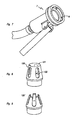
- a rock bolt assembly consists of a standard rock bolt 1 having threaded first and second ends 1a, 1b, a standard expansion shell type mechanical anchor 2 threaded onto the rock bolt first end 1 a and a rock bolt post-grouting apparatus 100.
- the post-grouting apparatus 100 has an elongate sleeve 101 and an end fitting 102.
- the elongate sleeve 101 is configured to receive the rock bolt 1 with the rock bolt first end 1a extending beyond the sleeve first end 101a and the rock bolt second end 1b extending beyond the sleeve second end 101b.
- the sleeve 101 will typically have a length such that it extends from adjacent the expansion shell 2 at the rock bolt first end 1a to adjacent the threaded second end 1b of the rock bolt, being a length typically of the order of 2 m.
- the sleeve 101 will typically be formed of a plastics material and is provided with corrugations 10 la which assist in anchoring the sleeve 101 with respect to the grout.
- the end fitting 102 is here in the form of a female component 103 and a male component 104, as depicted in greater detail in Figures 3 to 6 .
- the female component 103 is attached to the sleeve second end 101b by way of an annular flange 105.
- the rock bolt second end 1b extends through the end fitting 102 via apertures 106,107 provided in the female and male components 103,104.
- the female component 103 is in the general form of a cup, having a semi-spherical concavity 108 facing away from the sleeve 101.
- the end fitting female component 103 has a partly spherical outer surface 109 which engages a roof plate 3 which bears against the rock face 4 surrounding the rock bolt hole 5 in the usual manner.
- the male component 104 is in the form of a modified nut having a nut drive surface 110 and with the central aperture 107 being threaded for engagement with the threads of the rock bolt second end 1b.
- the leading end of the nut 104 is provided with three radial protrusions 111 each having a convex semi-spherical surface generally complementary to the concavity 108 of the female cup 103.
- grout passages 112 are defined at the interface between the nut 104 and cup 103 in the spaces between the radial protrusions 111. These grout passages 112 communicate the exterior of the end fitting 102 with the interior of the sleeve 101, thereby providing a passage for the injection of grout into the sleeve 101.
- the nut 104 is retained in position with the protrusions 111 abutting the wall of the concavity 108 of the cup 103 by way of a retaining clip 113 engaging grooves 114, 115 provided respectively in the wall of the cup concavity 108 and the nut protrusions 111, as best depicted in Figure 1 .
- This retention is purely for handling and transport purposes, as in use the nut 104 secures the cup 102 against the roof plate 3.
- any misalignment of the cup 103 resulting from misalignment of the roof plate when the rock face is uneven, will have no adverse effect.
- the relationship between the nut protrusions 111 and the wall of the cup concavity 108 provide for transfer of compressive loads from the nut 104 to the cup 102, which are in turn transferred to the rock face by way of the roof plate 3. These compressive loads are developed in reaction to the tensile loads in the bolt 1 resulting from tensioning of the bolt I by way of the nut 104.
- the outer part spherical surface 109 of the cup 103 is provided with coupling means, in the form of slots 116, for engagement with corresponding pins 6 provided in a standard grout delivery hose coupling 7 as depicted in Figure 8 .
- the end fitting could be a single component with grout passages extending therethrough, with a separate nut being provided to bear against the end fitting when tensioning the bolt.
- Such a configuration would, however, suffer from the potential misalignment problem discussed above if the rock face is uneven.
- Seal means here in the form of flaps 117, depicted in greater detail in Figures 3 , 4 and 6 , are provided for sealing the grout passages 112.
- the flaps 117 are displaceable between open and closed positions, with the flaps being biased towards the closed position (depicted in solid cross section).
- the passages 112 are substantially sealed to prevent the flow of grout down through the passages 112 and out of the end fitting 102.
- the flow deflects the flaps 117 to the open position (depicted in phantom) enabling the flow of grout through the passages 112 and into the sleeve 101.
- the biasing action of the flaps 117 moves them to the closed position, with the weight of the grout above the flaps 117 also tending to force the flaps 117 to the closed position.
- the flaps 117 are integrally formed with a ring-like member 118.
- the ring-like member 118 is mounted in a groove 119 provided around the periphery of the nut 104 directly beneath the radial protrusions 111, as best depicted in Figure 1 .
- the ring-like member 118 and flaps 117 are moulded from a resilient plastics material, with the resilience of the plastics material providing the biasing force tending to close the flaps 117.
- the flaps 117 might alternatively be spring biased utilising a separate spring mechanism, however the simple plastic moulding avoids the difficulties which might be associated with clogging of any spring mechanisms with grout.
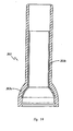
- the first end 101a of the sleeve is provided with a tapered cap 120, depicted in further detail in Figure 8 .
- the tapered cap 120 has a central open passage 121 through which the rock bolt I passes and a plurality of apertures 122 in the cap side wall to enable passage of grout therethrough. Whilst the cap of Figure 8 has the apertures 122 spaced from the tapered end of the cap, it is envisaged that the apertures might extend to the tapered end as depicted in the variant of the cap 120'depicted in Figure 9 .
- a rock bolt assembly will typically be provided with the expansion shell 2 and post-grouting apparatus 100 already assembled onto the rock bolt 1.
- the rock bolt assembly is installed into the rock bolt hole with a roof plate 3 in place on the rock face 4.
- the expansion shell 2 is then expanded by rotating the rock bolt 1 via the nut drive surface 110 of the nut 104 in the usual manner, and the bolt tensioned by further tightening of the nut 104.
- the nut bears against the cup 102 which in-turn bears against the roof plate 3, transferring compressive loads to the rock face 4.
- a grout delivery hose is then attached to the end fitting 102 by way of the hose coupling 7, and grout injected into the grout passages 112, deflecting the seal flaps 117 to the open position.
- the grout flows through the passages 112 and up through the interior annular passage defined between the sleeve 101 and the rock bolt 1, through the apertures 122 in the tapered cap 120 and down through the outer annular passage between the sleeve 101 and the wall of the rock bolt hole 5.
- the resiliency of the plastic seal flaps 117 along with the weight of the grout, forces the seal flaps 117 to the closed position, preventing grout from escaping from the inner annular passage between the sleeve 101 and the rock bolt 1. Full encapsulation of the rock bolt I can accordingly be retained.
- the coupling 7 is then disengaged from the end fitting 102 to complete the installation process.
- a coupling member 123 Whilst the rock bolt remains substantially fully encapsulated with grout within the hole, to thereby protect it against corrosion as well as providing for load transfer between the rock bolt 1 and surrounding rock, the nut 104 and rock bolt second end 1b remain exposed, and therefore subject to corrosion.
- a coupling member 123 can be utilised.
- the coupling member 123 has an internal cavity 124 opening onto the first end 123a of the coupling member.
- Pins 125 are provided in the first end 123a of the coupling member to enable the coupling member 123 to be coupled to the end fitting 102 described above in the same manner as the hose coupling 7 of Figure 8 .
- the coupling member 123 also has an inlet port 126, here positioned at the coupling member second end 123b, which can be directly coupled to a grout delivery hose by any suitable means.
- a valve means here in the form of a gate valve 127 is provided to seal the inlet port.
- the coupling member 123 is sized such that it encloses the rock bolt second end 1b, and the portion of the nut 104 protruding beyond the cup 102, within the cavity 124 of the coupling member 123.
- the coupling member 123 will be secured to the end fitting 102 in the same manner as described above, with a grout delivery hose being coupled to the inlet port 126.
- Grout is injected through the coupling member 123 and into the grout passages 112 in the same manner as discussed above.
- the valve 127 is closed and the coupling member 123 is left in situ coupled to the cup 102, with the grout delivery hose being removed from the inlet port 126. Accordingly, the coupling member 123 remains filled with grout, fully encasing the rock bolt second end 1b and nut 104, protecting the same from corrosion.
- the seal flaps 117 might be omitted from the grout delivery apparatus when such a coupling member 123 is used, however it is preferred that the seal flaps remain to provide an added safeguard from the possible escape of grout from the sleeve 101.
- the coupling member 123 remains in situ, and accordingly one coupling member 123 is required for each rock bolt, it is preferred that the coupling member be moulded from plastics material so as to reduce costs.
- an alternate post-grouting apparatus 200 is depicted.
- This alternate post-grouting apparatus has an elongate sleeve 201 as per that of Figures 1 and 2 and an end fitting 202 in the form of a female cup-like component 203 and a male nut-like component 204 similar to that of Figures 1 to 4 .
- a plastic cap 230 substantially covers the nut 204.
- the cap 230 consists of a nut covering portion 231 which covers the nut drive surface 210 of the nut 204 and an annular flange 232 which covers the nut protrusions 211.
- Apertures 233 are formed in the flange portion 232 enabling access to the grout passages 212 defined in the spaces between the nut protrusions 211.
- Walls 234 extend from the flange apertures 233 so as to cover the side walls of the grout passages 212.
- the peripheral edge 235 of the cap annular flange 232 engages a groove 214 provided in the wall of the concavity 208 of the cup 203. This engagement retains the assembly of the cap 230, nut 204 and cup 203 during transport and handling of the rock bolt assembly.
- the plastic cap 230 acts to protect the nut 204 of the end fitting 202 against corrosion. As the cap 230 can be installed during initial assembly of the rock bolt assembly prior to installation to a rock bolt hole, the access difficulties associated with fitting of the coupling member 123 of Figure 10 to an already installed rock bolt assembly in the high roof of a mine are eliminated.
- the side walls of the nut covering portion 231 of the plastic cap 230 are approximately 2 mm thick, whilst the end wall is approximately 4 mm thick, with this thicker wall being suitable to bear the driving load applied by the installation rig during rock bolt installation without tearing of the cap 230.
- the nut drive portion 210 of the nut is of a reduced size as compared to that of the nut drive portion 110 of the apparatus of Figures 1 to 4 , thereby enabling a standard rock bolt installation spanner socket to be utilised.
- the nut drive portion 210 has a blind threaded aperture receiving the rock bolt second end 1b, thereby providing a closed end face on the drive portion. This thus prevents the rock bolt second end 1b from extending beyond the end of the nut 204 and damaging the plastic cap 230.
- the nut drive portion 210 may be provided with a through aperture in the same manner as the nut 104 of Figures 1 to 4, with the rock bolt being provided with a thread of a limited length equal to or shorter than the length of the nut drive portion 210 such that the rock bolt cannot be threaded into the aperture sufficiently for the rock bolt second end 1b to protrude beyond the nut.
- the cap 230 may be provided with seal means in the form of flaps 217 covering the apertures 233. These flaps 217 are biased to the closed position as depicted in Figure 13 , but upon injection of grout the flaps 217 are deflected upwardly to an open position allowing grout to enter the grout passages 212. These flaps 217 accordingly replace the flaps 117 of the apparatus of Figures 1 to 4 . These flaps 217 also act to provide extra corrosion protection, however they may not be necessary to prevent the escape of grout where a high viscosity grout is utilised.
- the cap 203 may be formed of a stiff plastics material.
- longitudinally extending stiffening ribs 205a have been utilised which act to stiffen the flange 205 while still providing a passage for grout to flow between the flange 205 and the wall of the rock bolt hole 5.
- a composite cup 303 as depicted in Figure 14 may be utilised, including a plastic outer skin 303a and steel liner 303b providing the required strength.
- the cup 203 might be formed of stainless steel, providing strength and corrosion resistance.
- Composite cup 403 includes a plastic main body 403a incorporating a plastic flange 405 to which the sleeve 101 is fixed.
- a carbon steel inner liner/shroud 403b is provided in the concavity of the cup-like component 403.
- the associated male nut-like component 104/204 which will also be typically be formed of carbon steel, engages this inner shroud 403b in use.
- the shroud 403b hence effectively acts as a wear lining preventing damage to the plastic main body 403a from the male nut-like component 104/204.
- a stainless steel outer shroud 403c is provided on the exterior face of the cup- like component in the region intersecting the cup-like end of the component and the flange 405, and extending along the cup-like end. This stainless steel outer shroud 403c will bear against the roof plate 3 in use, again preventing wear of the plastic main body 403a. Forming the outer shroud 403c from stainless steel will inhibit corrosion of the same.
- the post-grouting apparatus is also applicable for use with cable bolt type rock bolts.
- the modified nut described above can be utilised in place of the standard tensioning nut.
- the male component of the end fitting would be formed as a modified barrel, rather than a nut, to replace the standard barrel of the barrel and wedge assembly.
Landscapes
- Engineering & Computer Science (AREA)
- Mining & Mineral Resources (AREA)
- Structural Engineering (AREA)
- Life Sciences & Earth Sciences (AREA)
- General Life Sciences & Earth Sciences (AREA)
- Geochemistry & Mineralogy (AREA)
- Geology (AREA)
- Piles And Underground Anchors (AREA)
- Consolidation Of Soil By Introduction Of Solidifying Substances Into Soil (AREA)
- Road Signs Or Road Markings (AREA)
- Walking Sticks, Umbrellas, And Fans (AREA)
Claims (18)
- Dispositif de post-cimentation d'un boulon d'ancrage, comprenant :- un manchon allongé (101) ayant des première et deuxième extrémités (101a, 101b) et étant conçu pour recevoir un boulon d'ancrage (1) avec une première extrémité (1a) de celui-ci qui s'étend au-delà de ladite première extrémité de manchon (101 a) et une deuxième extrémité (1b) de celui-ci qui s'étend au-delà de ladite deuxième extrémité de manchon (101b),- une pièce de fixation ou d'ajustement d'extrémité (102) montée sur ladite deuxième extrémité de manchon (101b), ladite pièce de fixation d'extrémité (102) ayant une ouverture centrale (106, 107) destinée à recevoir ledit boulon d'ancrage (1) et un ou plusieurs passages de ciment (112) mettant en communication l'extérieur de ladite pièce de fixation ou d'ajustement d'extrémité (102) avec l'intérieur dudit manchon (101),caractérisé en ce que le dispositif comprend un moyen d'étanchéité (117, 217) destiné à fermer de façon étanche lesdits un ou plusieurs passages de ciment (112), ledit moyen d'étanchéité (117, 217) étant déplaçable entre des positions ouverte et fermée, dans lequel ledit moyen d'étanchéité (117, 217) est sollicité vers ladite position fermée à laquelle lesdits un ou plusieurs passages de ciment (112) sont sensiblement fermés de façon étanche et l'injection de ciment dans ladite pièce de fixation ou d'ajustement d'extrémité (102) par le biais dudit/desdits passage(s) déforme ledit moyen d'étanchéité (117, 217) vers ladite position ouverte en permettant l'écoulement de ciment à travers lesdits un ou plusieurs passages de ciment (112) et dans ledit manchon (101).
- Dispositif selon la revendication 1, dans lequel ladite pièce de fixation d'extrémité (102) comprend : un composant femelle (103) fixé à ladite deuxième extrémité de manchon (101b) et définissant une concavité (108) non orientée vers ledit manchon (101), et un composant mâle (104) conçu pour être vissé sur ladite deuxième extrémité de boulon d'ancrage (1b) et pour être reçu dans ladite concavité de composant femelle (108) de manière à transférer des charges de compression entre lesdits composants mâle et femelle (104, 103), dans lequel lesdits un ou plusieurs passages de ciment (112) sont définis entre lesdits composants mâle et femelle (104, 103) et ledit composant mâle (104) est doté d'une surface d'entraînement d'écrou (110) pour visser ledit composant mâle (104) sur ladite deuxième extrémité de boulon d'ancrage (1b) pour mettre sous tension ledit boulon d'ancrage (1).
- Dispositif selon la revendication 1, dans lequel ladite concavité de composant femelle (108) est semi-sphérique et ledit composant mâle (104) est doté d'une surface périphérique semi-sphérique convexe complémentaire.
- Dispositif selon la revendication 2, dans lequel ledit composant femelle (103) est doté d'un moyen de couplage (116) sur une surface périphérique (109) de celui-ci pour un couplage à un raccord de tuyau de délivrance de ciment (107).
- Dispositif selon la revendication 2, dans lequel une pluralité desdits passages (112) sont définis sous la forme d'évidements dans la surface périphérique dudit composant mâle (104).
- Dispositif selon la revendication 5, dans lequel ledit moyen d'étanchéité comprend un volet (117, 217) associé à chacun desdits passages de ciment (112).
- Dispositif selon la revendication 6, dans lequel lesdits volets (117, 217) sont formés d'une matière plastique souple.
- Dispositif selon la revendication 7, dans lequel ledit moyen d'étanchéité comprend un élément en forme d'anneau (118) s'étendant autour dudit composant mâle (104), lesdits volets étant formés de manière solidaire avec ledit élément en forme d'anneau (118).
- Dispositif selon la revendication 2, comprenant en outre un couvercle en matière plastique (230) recouvrant au moins sensiblement ledit composant mâle de pièce de fixation d'extrémité (104, 204).
- Dispositif selon la revendication 9, dans lequel ledit couvercle en matière plastique (230) incorpore ledit moyen d'étanchéité (217).
- Dispositif selon la revendication 9, dans lequel un bord périphérique (235) dudit couvercle (230) est conçu pour s'engager avec une rainure (214) ménagée dans ladite concavité de composant femelle de pièce de fixation d'extrémité (208) pour retenir de cette manière l'assemblage dudit couvercle en matière plastique (230), dudit composant mâle de pièce de fixation d'extrémité (204) et dudit composant femelle de pièce de fixation d'extrémité (203).
- Dispositif selon la revendication 1, dans lequel ledit dispositif est doté d'un couvercle incliné (120) au niveau de ladite première extrémité de manchon (101a), ledit couvercle incliné (120) étant doté d'un passage ouvert central (121) pour la réception dudit boulon d'ancrage (1) et d'une pluralité d'ouvertures (122) dans une paroi latérale dudit couvercle (120) pour le passage de ciment à travers.
- Dispositif selon la revendication 2, dans lequel ledit composant femelle est formé à partir d'acier inoxydable.
- Dispositif selon l'une quelconque des revendication 1 à 13 comprenant : un élément de couplage (123) ayant des première et deuxième extrémités (123a, 123b) et une ouverture de cavité interne (124) sur ladite première extrémité d'élément de couplage (123a), ladite première extrémité d'élément de couplage (123a) étant conçue pour être couplée à ladite pièce de fixation d'extrémité (102) avec ladite cavité d'élément de couplage (124) en communication avec lesdits un ou plusieurs passages de ciment (112), ledit élément de couplage (123) étant doté d'un orifice d'entrée (16) conçu pour être couplé à un tuyau de délivrance de ciment et d'un moyen de vanne (127) pour fermer de façon étanche ledit orifice d'entrée (126), dans lequel ledit élément de couplage (123) est conçu pour enfermer ladite deuxième extrémité de boulon d'ancrage (1b) dans ladite cavité d'élément de couplage (124).
- Dispositif selon la revendication 14, dans lequel ledit élément de couplage (123) est formé à partir d'une matière plastique.
- Dispositif selon la revendication 14, dans lequel ladite pièce de fixation d'extrémité (102) comprend: un composant femelle (103) fixé à ladite deuxième extrémité de manchon (101b) et définissant une concavité (108) non orientée vers ledit manchon (101), et un composant mâle (104) conçu pour être vissé sur ladite deuxième extrémité de boulon d'ancrage (1b) et pour être reçu dans ladite concavité de composant femelle (108) et engager sa paroi, dans lequel lesdits un ou plusieurs passages de ciment (112) sont définis au niveau de l'interface entre lesdits composants mâle et femelle (104, 103) et ledit composant mâle (104) est doté d'une surface d'entraînement d'écrou (110) pour visser ledit composant mâle (104) sur ladite deuxième extrémité de boulon d'ancrage (1b) pour mettre sous tension ledit boulon d'ancrage (1).
- Dispositif selon la revendication 16, dans lequel ladite concavité de composant femelle (108) est semi-sphérique et ledit composant mâle (104) est doté d'une surface périphérique semi-sphérique convexe d'accouplement pour engager ladite concavité semi-sphérique (108).
- Assemblage de boulon d'ancrage comprenant: un dispositif selon l'une quelconque des revendications 1 à 17, un boulon d'ancrage (1) ayant des première et deuxième extrémités (1a, 1b), ledit boulon d'ancrage (1) étant reçu par ledit manchon allongé (101), ladite première extrémité de boulon d'ancrage (1a) s'étendant au-delà de ladite première extrémité de manchon (101a) et ladite deuxième extrémité de boulon d'ancrage (1b) s'étendant au-delà de ladite deuxième extrémité de manchon (101b), ledit boulon d'ancrage (1) étant en outre reçu par ladite ouverture centrale (106, 107) de pièce de fixation d'extrémité (102).
Priority Applications (1)
| Application Number | Priority Date | Filing Date | Title |
|---|---|---|---|
| SI200331979T SI1546508T1 (sl) | 2002-08-02 | 2003-08-01 | Priprava za naknadno zapolnjevanje geotehničnih sider |
Applications Claiming Priority (5)
| Application Number | Priority Date | Filing Date | Title |
|---|---|---|---|
| AU2002950558 | 2002-08-02 | ||
| AU2002950558A AU2002950558A0 (en) | 2002-08-02 | 2002-08-02 | Rock bolt post grouting apparatus |
| AU2002953569A AU2002953569A0 (en) | 2002-12-24 | 2002-12-24 | Rock bolt |
| AU2002953569 | 2002-12-24 | ||
| PCT/AU2003/000967 WO2004013463A1 (fr) | 2002-08-02 | 2003-08-01 | Appareil de post-cimentation de boulon d'ancrage |
Publications (3)
| Publication Number | Publication Date |
|---|---|
| EP1546508A1 EP1546508A1 (fr) | 2005-06-29 |
| EP1546508A4 EP1546508A4 (fr) | 2006-01-18 |
| EP1546508B1 true EP1546508B1 (fr) | 2011-01-05 |
Family
ID=31496426
Family Applications (1)
| Application Number | Title | Priority Date | Filing Date |
|---|---|---|---|
| EP03766066A Expired - Lifetime EP1546508B1 (fr) | 2002-08-02 | 2003-08-01 | Appareil de post-cimentation de boulon d'ancrage |
Country Status (8)
| Country | Link |
|---|---|
| US (1) | US7381013B1 (fr) |
| EP (1) | EP1546508B1 (fr) |
| AT (1) | ATE494455T1 (fr) |
| CA (1) | CA2494781C (fr) |
| DE (1) | DE60335638D1 (fr) |
| PT (1) | PT1546508E (fr) |
| SI (1) | SI1546508T1 (fr) |
| WO (1) | WO2004013463A1 (fr) |
Cited By (1)
| Publication number | Priority date | Publication date | Assignee | Title |
|---|---|---|---|---|
| US8998541B2 (en) | 2011-02-24 | 2015-04-07 | Suomen Metallityö Oy | Rock bolt |
Families Citing this family (25)
| Publication number | Priority date | Publication date | Assignee | Title |
|---|---|---|---|---|
| CZ301263B6 (cs) * | 2003-01-24 | 2009-12-23 | Ankra, S.R.O. | Horninový injektážní svorník a zpusob jeho výroby |
| US7717650B2 (en) * | 2003-12-02 | 2010-05-18 | Dywidag-Systems International, U.S.A., Inc. | Roof truss shoe having wedge retention device and method of using the same |
| DE102006000042A1 (de) * | 2006-01-31 | 2007-08-02 | Hilti Ag | Adapterteil eines selbstbohrenden Gebirgsankers |
| US20120251245A1 (en) * | 2006-07-07 | 2012-10-04 | Excel Mining Systems Llc | Low Profile Cable Bolt Heads |
| US8137032B2 (en) * | 2006-12-19 | 2012-03-20 | Minova International Limited | Anchor with grout jacket |
| US7802943B2 (en) * | 2008-01-10 | 2010-09-28 | Dsi Ground Support Inc. | Low profile mine roof support |
| CA2742253C (fr) * | 2008-11-24 | 2016-01-12 | Fci Holdings Delaware, Inc. | Cable gaine |
| AU2011274289B2 (en) * | 2010-06-30 | 2013-02-28 | DSI Underground Australia Pty Limited | An apparatus for post-grouting a cable bolt, cable bolt assembly and method of installing a cable bolt |
| PL2603666T3 (pl) * | 2010-08-10 | 2017-09-29 | DSI Underground IP Holdings Luxembourg S.à r.L. | Iniektowana kotwa linowa |
| CL2011000042A1 (es) * | 2011-01-07 | 2011-06-17 | Sistema de fortificacion que comprende una barra helicoidal estandar, una cabeza de expansion adaptada a la rosca de la barra, un elemento de material plastico, un tubo de plastico corrugado, una placa de fortificacion estandar y una tuerca de fortificacion roscada segun el perno helicoidal que utiliza. | |
| AT13228U1 (de) * | 2011-01-31 | 2013-08-15 | Atlas Copco Mai Gmbh | Schutzvorrichtung für (gebirgs-)anker und reibrohranker |
| CA2798203A1 (fr) * | 2011-12-14 | 2013-06-14 | Rsc Mining (Pty) Ltd. | Boulon d'ancrage |
| AU2013204178B2 (en) * | 2012-09-06 | 2015-11-26 | DSI Underground Australia Pty Limited | A rock bolt assembly |
| FI125339B (fi) | 2012-12-10 | 2015-08-31 | Suomen Metallityö Oy | Kallioankkuripultti |
| PL3019700T3 (pl) | 2013-07-12 | 2018-03-30 | Minova International Limited | Podatna kotwa skalna |
| SE1551687A1 (sv) * | 2013-07-30 | 2015-12-21 | Dywidag Systems Int Pty Ltd | Friction bolt assembly |
| AU2015309690A1 (en) * | 2014-08-28 | 2017-04-20 | Kevin Frank STACEY | Rock bolt and method of stabilizing excavations |
| MX392334B (es) * | 2015-06-23 | 2025-03-24 | Epiroc Drilling Tools Ab | Sistema de entrega de lechada. |
| CA2957748C (fr) | 2017-02-13 | 2018-05-01 | Lyle Kenneth Adams | Joint de boulon a roche |
| CN109026101A (zh) * | 2018-09-13 | 2018-12-18 | 于守东 | 一种矿用锚注装置及其使用方法 |
| EP4090831B1 (fr) * | 2020-04-01 | 2024-01-03 | Innovative Mining Products (Pty) Ltd | Ensemble boulon ancré de manière adhésive |
| US20240175360A1 (en) * | 2021-03-23 | 2024-05-30 | Cmte Development Limited | Carbon Fiber Rock Bolt |
| CN113339034B (zh) * | 2021-07-07 | 2023-06-20 | 六盘水师范学院 | 一种适用于隧道支护及稳定性测量的智能锚杆 |
| EP4130426B1 (fr) * | 2021-08-05 | 2024-10-09 | Sandvik Mining and Construction Australia (Production/Supply) Pty Ltd | Douille de commande pour l'installation d'un boulon de renforcement au sol |
| CN119266882B (zh) * | 2024-10-18 | 2025-10-28 | 中铁四局集团有限公司 | 一种新型让压锚杆的应用方法 |
Family Cites Families (17)
| Publication number | Priority date | Publication date | Assignee | Title |
|---|---|---|---|---|
| US3665717A (en) * | 1971-01-14 | 1972-05-30 | Soil Sampling Service Inc | Method and apparatus for installing elongated rods in unstable earth formations |
| JPS534326B2 (fr) * | 1975-01-09 | 1978-02-16 | ||
| DE2707238C3 (de) * | 1977-02-19 | 1979-07-12 | Dyckerhoff & Widmann Ag, 8000 Muenchen | Korrosionsgeschütztes Zugglied für einen vorspannbaren Anker im Festgestein |
| DE2732059A1 (de) | 1977-07-15 | 1979-02-01 | Ortwin M Zeissig | Bohrlochverschluss zum zurueckhalten von injektionsfluessigkeiten, insbesondere fuer den berg- und tunnelbau |
| FR2560285B1 (fr) * | 1984-02-23 | 1987-12-04 | Louis Claude | Procede pour enfoncer et sceller une armature dans le sol, dispositif et armature pour la mise en oeuvre de ce procede |
| FR2604744B1 (fr) * | 1986-10-02 | 1991-04-19 | Francois Entreprises Cfe Sa Ci | Procede et dispositif d'ancrage sous contrainte |
| DE3902727A1 (de) * | 1989-01-31 | 1990-08-02 | Willich F Gmbh & Co | Gfk-gebirgsklebeanker |
| DE3912526A1 (de) * | 1989-04-17 | 1990-10-18 | Hilti Ag | Verankerung an plattenfoermigen bauteilen |
| CA2087923A1 (fr) * | 1992-01-23 | 1993-07-24 | Johannes Jacobus Gouws | Methode de remplissage d'un trou de forage |
| DE4204533C2 (de) * | 1992-02-15 | 1994-03-17 | Gd Anker Gmbh & Co Kg | Injektionsbohranker |
| NO176069C (no) * | 1992-09-09 | 1999-06-25 | Irsta Stolindustri As | Anordning for forankring og gysing av bergbolt |
| GB2283291B (en) * | 1993-09-20 | 1996-08-14 | Bridon Plc | Roof bolt |
| AU2020195A (en) | 1994-05-24 | 1995-11-30 | Ani Corporation Limited, The | Post-grouted rock bolt |
| AUPP894199A0 (en) * | 1999-03-01 | 1999-03-25 | Witzand, Hendrik Hermanus Gerhardus | Friction bolt with flexible core |
| AU5504800A (en) | 1999-09-03 | 2001-03-08 | Dywidag-Systems International Pty. Limited | Rock bolt post grouting apparatus and method |
| FI110540B (fi) * | 1999-12-02 | 2003-02-14 | Sandvik Tamrock Oy | Sovitelma juotosaineen syöttämiseksi |
| AUPS310802A0 (en) * | 2002-06-21 | 2002-07-11 | Industrial Rollformers Pty Limited | Yielding cable bolt |
-
2003
- 2003-08-01 AT AT03766066T patent/ATE494455T1/de active
- 2003-08-01 SI SI200331979T patent/SI1546508T1/sl unknown
- 2003-08-01 EP EP03766066A patent/EP1546508B1/fr not_active Expired - Lifetime
- 2003-08-01 PT PT03766066T patent/PT1546508E/pt unknown
- 2003-08-01 US US10/523,355 patent/US7381013B1/en not_active Expired - Fee Related
- 2003-08-01 WO PCT/AU2003/000967 patent/WO2004013463A1/fr not_active Ceased
- 2003-08-01 DE DE60335638T patent/DE60335638D1/de not_active Expired - Lifetime
- 2003-08-01 CA CA2494781A patent/CA2494781C/fr not_active Expired - Fee Related
Cited By (1)
| Publication number | Priority date | Publication date | Assignee | Title |
|---|---|---|---|---|
| US8998541B2 (en) | 2011-02-24 | 2015-04-07 | Suomen Metallityö Oy | Rock bolt |
Also Published As
| Publication number | Publication date |
|---|---|
| WO2004013463A1 (fr) | 2004-02-12 |
| US7381013B1 (en) | 2008-06-03 |
| SI1546508T1 (sl) | 2011-05-31 |
| CA2494781C (fr) | 2010-10-26 |
| EP1546508A1 (fr) | 2005-06-29 |
| DE60335638D1 (de) | 2011-02-17 |
| EP1546508A4 (fr) | 2006-01-18 |
| ATE494455T1 (de) | 2011-01-15 |
| PT1546508E (pt) | 2011-03-09 |
| CA2494781A1 (fr) | 2004-02-12 |
Similar Documents
| Publication | Publication Date | Title |
|---|---|---|
| EP1546508B1 (fr) | Appareil de post-cimentation de boulon d'ancrage | |
| CA2530323C (fr) | Boulon d'ancrage | |
| EP3730736B1 (fr) | Boulon de friction | |
| AU2008207662B2 (en) | End coupling for a rock bolt | |
| EP2603666B1 (fr) | Boulon à câble entièrement cimenté | |
| US6474910B2 (en) | Rockbolt assembly | |
| US20100221072A1 (en) | Bolt anchor | |
| AU2003100644B4 (en) | Rock Bolt Post Grouting Apparatus | |
| AU2003231588B2 (en) | Rock Bolt Post Grouting Apparatus | |
| US20030219316A1 (en) | Rock bolt | |
| AU674788B2 (en) | Anchor bolt for stabilising rock strata | |
| AU2016228128B2 (en) | Fitting for a rock bolt and rock bolt assemblies including same | |
| AU2003246456A1 (en) | Rock bolt post grouting apparatus | |
| AU777428B2 (en) | Rock bolt | |
| AU5504800A (en) | Rock bolt post grouting apparatus and method | |
| ES2358738T3 (es) | Aparato de aplicación posterior de mortero a pernos de anclaje. | |
| KR200428901Y1 (ko) | 관입 그라운드 앵커용 노즈 콘 | |
| JPS62211423A (ja) | アンカ−体の造成工法 | |
| AU2004202913B2 (en) | Rock Bolt Assembly | |
| AU2018410544B2 (en) | Impact absorber for rock bolt | |
| KR200217015Y1 (ko) | 록볼트 | |
| JPH10280876A (ja) | 推進管用の滑剤注入孔 | |
| AU2015101246B4 (en) | Rock bolt fitting and assembly including same | |
| AU2011295644B2 (en) | Mechanical anchor for bolt | |
| NZ614611A (en) | A rock bolt assembly |
Legal Events
| Date | Code | Title | Description |
|---|---|---|---|
| PUAI | Public reference made under article 153(3) epc to a published international application that has entered the european phase |
Free format text: ORIGINAL CODE: 0009012 |
|
| 17P | Request for examination filed |
Effective date: 20050224 |
|
| AK | Designated contracting states |
Kind code of ref document: A1 Designated state(s): AT BE BG CH CY CZ DE DK EE ES FI FR GB GR HU IE IT LI LU MC NL PT RO SE SI SK TR |
|
| AX | Request for extension of the european patent |
Extension state: AL LT LV MK |
|
| RIC1 | Information provided on ipc code assigned before grant |
Ipc: 7E 21D 21/00 B Ipc: 7E 21D 20/02 A |
|
| DAX | Request for extension of the european patent (deleted) | ||
| A4 | Supplementary search report drawn up and despatched |
Effective date: 20051202 |
|
| 17Q | First examination report despatched |
Effective date: 20080818 |
|
| R17C | First examination report despatched (corrected) |
Effective date: 20091015 |
|
| GRAP | Despatch of communication of intention to grant a patent |
Free format text: ORIGINAL CODE: EPIDOSNIGR1 |
|
| RAP1 | Party data changed (applicant data changed or rights of an application transferred) |
Owner name: DYWIDAG-SYSTEMS INTERNATIONAL PTY LIMITED |
|
| GRAS | Grant fee paid |
Free format text: ORIGINAL CODE: EPIDOSNIGR3 |
|
| GRAA | (expected) grant |
Free format text: ORIGINAL CODE: 0009210 |
|
| AK | Designated contracting states |
Kind code of ref document: B1 Designated state(s): AT BE BG CH CY CZ DE DK EE ES FI FR GB GR HU IE IT LI LU MC NL PT RO SE SI SK TR |
|
| REG | Reference to a national code |
Ref country code: GB Ref legal event code: FG4D |
|
| REG | Reference to a national code |
Ref country code: CH Ref legal event code: EP |
|
| REG | Reference to a national code |
Ref country code: IE Ref legal event code: FG4D |
|
| REF | Corresponds to: |
Ref document number: 60335638 Country of ref document: DE Date of ref document: 20110217 Kind code of ref document: P |
|
| REG | Reference to a national code |
Ref country code: DE Ref legal event code: R096 Ref document number: 60335638 Country of ref document: DE Effective date: 20110217 |
|
| REG | Reference to a national code |
Ref country code: PT Ref legal event code: SC4A Free format text: AVAILABILITY OF NATIONAL TRANSLATION Effective date: 20110301 |
|
| REG | Reference to a national code |
Ref country code: SE Ref legal event code: TRGR |
|
| REG | Reference to a national code |
Ref country code: CH Ref legal event code: NV Representative=s name: ZIMMERLI, WAGNER & PARTNER AG |
|
| REG | Reference to a national code |
Ref country code: ES Ref legal event code: FG2A Ref document number: 2358738 Country of ref document: ES Kind code of ref document: T3 Effective date: 20110503 |
|
| REG | Reference to a national code |
Ref country code: NL Ref legal event code: VDEP Effective date: 20110105 |
|
| REG | Reference to a national code |
Ref country code: SK Ref legal event code: T3 Ref document number: E 9003 Country of ref document: SK |
|
| REG | Reference to a national code |
Ref country code: GR Ref legal event code: EP Ref document number: 20110400793 Country of ref document: GR Effective date: 20110513 |
|
| PG25 | Lapsed in a contracting state [announced via postgrant information from national office to epo] |
Ref country code: CY Free format text: LAPSE BECAUSE OF FAILURE TO SUBMIT A TRANSLATION OF THE DESCRIPTION OR TO PAY THE FEE WITHIN THE PRESCRIBED TIME-LIMIT Effective date: 20110105 Ref country code: NL Free format text: LAPSE BECAUSE OF FAILURE TO SUBMIT A TRANSLATION OF THE DESCRIPTION OR TO PAY THE FEE WITHIN THE PRESCRIBED TIME-LIMIT Effective date: 20110105 Ref country code: BE Free format text: LAPSE BECAUSE OF FAILURE TO SUBMIT A TRANSLATION OF THE DESCRIPTION OR TO PAY THE FEE WITHIN THE PRESCRIBED TIME-LIMIT Effective date: 20110105 |
|
| PG25 | Lapsed in a contracting state [announced via postgrant information from national office to epo] |
Ref country code: DK Free format text: LAPSE BECAUSE OF FAILURE TO SUBMIT A TRANSLATION OF THE DESCRIPTION OR TO PAY THE FEE WITHIN THE PRESCRIBED TIME-LIMIT Effective date: 20110105 Ref country code: EE Free format text: LAPSE BECAUSE OF FAILURE TO SUBMIT A TRANSLATION OF THE DESCRIPTION OR TO PAY THE FEE WITHIN THE PRESCRIBED TIME-LIMIT Effective date: 20110105 |
|
| PGFP | Annual fee paid to national office [announced via postgrant information from national office to epo] |
Ref country code: CH Payment date: 20110826 Year of fee payment: 9 Ref country code: BG Payment date: 20110830 Year of fee payment: 9 |
|
| PLBE | No opposition filed within time limit |
Free format text: ORIGINAL CODE: 0009261 |
|
| STAA | Information on the status of an ep patent application or granted ep patent |
Free format text: STATUS: NO OPPOSITION FILED WITHIN TIME LIMIT |
|
| PG25 | Lapsed in a contracting state [announced via postgrant information from national office to epo] |
Ref country code: RO Free format text: LAPSE BECAUSE OF FAILURE TO SUBMIT A TRANSLATION OF THE DESCRIPTION OR TO PAY THE FEE WITHIN THE PRESCRIBED TIME-LIMIT Effective date: 20110105 |
|
| PGFP | Annual fee paid to national office [announced via postgrant information from national office to epo] |
Ref country code: SI Payment date: 20110816 Year of fee payment: 9 Ref country code: GR Payment date: 20110830 Year of fee payment: 9 Ref country code: PT Payment date: 20110817 Year of fee payment: 9 |
|
| 26N | No opposition filed |
Effective date: 20111006 |
|
| REG | Reference to a national code |
Ref country code: DE Ref legal event code: R097 Ref document number: 60335638 Country of ref document: DE Effective date: 20111006 |
|
| PG25 | Lapsed in a contracting state [announced via postgrant information from national office to epo] |
Ref country code: MC Free format text: LAPSE BECAUSE OF NON-PAYMENT OF DUE FEES Effective date: 20110831 |
|
| REG | Reference to a national code |
Ref country code: IE Ref legal event code: MM4A |
|
| PG25 | Lapsed in a contracting state [announced via postgrant information from national office to epo] |
Ref country code: IE Free format text: LAPSE BECAUSE OF NON-PAYMENT OF DUE FEES Effective date: 20110801 |
|
| REG | Reference to a national code |
Ref country code: PT Ref legal event code: MM4A Free format text: LAPSE DUE TO NON-PAYMENT OF FEES Effective date: 20130201 |
|
| REG | Reference to a national code |
Ref country code: CH Ref legal event code: PL |
|
| PG25 | Lapsed in a contracting state [announced via postgrant information from national office to epo] |
Ref country code: LI Free format text: LAPSE BECAUSE OF NON-PAYMENT OF DUE FEES Effective date: 20120831 Ref country code: CH Free format text: LAPSE BECAUSE OF NON-PAYMENT OF DUE FEES Effective date: 20120831 |
|
| REG | Reference to a national code |
Ref country code: SI Ref legal event code: KO00 Effective date: 20130306 |
|
| REG | Reference to a national code |
Ref country code: GR Ref legal event code: ML Ref document number: 20110400793 Country of ref document: GR Effective date: 20130304 |
|
| PG25 | Lapsed in a contracting state [announced via postgrant information from national office to epo] |
Ref country code: LU Free format text: LAPSE BECAUSE OF NON-PAYMENT OF DUE FEES Effective date: 20110801 Ref country code: PT Free format text: LAPSE BECAUSE OF NON-PAYMENT OF DUE FEES Effective date: 20130201 Ref country code: SI Free format text: LAPSE BECAUSE OF NON-PAYMENT OF DUE FEES Effective date: 20120802 Ref country code: GR Free format text: LAPSE BECAUSE OF NON-PAYMENT OF DUE FEES Effective date: 20130304 |
|
| PG25 | Lapsed in a contracting state [announced via postgrant information from national office to epo] |
Ref country code: HU Free format text: LAPSE BECAUSE OF FAILURE TO SUBMIT A TRANSLATION OF THE DESCRIPTION OR TO PAY THE FEE WITHIN THE PRESCRIBED TIME-LIMIT Effective date: 20110105 |
|
| PGFP | Annual fee paid to national office [announced via postgrant information from national office to epo] |
Ref country code: TR Payment date: 20130726 Year of fee payment: 11 |
|
| PG25 | Lapsed in a contracting state [announced via postgrant information from national office to epo] |
Ref country code: BG Free format text: LAPSE BECAUSE OF NON-PAYMENT OF DUE FEES Effective date: 20120831 |
|
| PGFP | Annual fee paid to national office [announced via postgrant information from national office to epo] |
Ref country code: CZ Payment date: 20140723 Year of fee payment: 12 Ref country code: DE Payment date: 20140827 Year of fee payment: 12 Ref country code: FI Payment date: 20140827 Year of fee payment: 12 |
|
| PGFP | Annual fee paid to national office [announced via postgrant information from national office to epo] |
Ref country code: AT Payment date: 20140721 Year of fee payment: 12 Ref country code: GB Payment date: 20140827 Year of fee payment: 12 Ref country code: SK Payment date: 20140718 Year of fee payment: 12 Ref country code: FR Payment date: 20140818 Year of fee payment: 12 Ref country code: SE Payment date: 20140827 Year of fee payment: 12 Ref country code: ES Payment date: 20140826 Year of fee payment: 12 |
|
| PGFP | Annual fee paid to national office [announced via postgrant information from national office to epo] |
Ref country code: IT Payment date: 20140825 Year of fee payment: 12 |
|
| REG | Reference to a national code |
Ref country code: DE Ref legal event code: R119 Ref document number: 60335638 Country of ref document: DE |
|
| REG | Reference to a national code |
Ref country code: SE Ref legal event code: EUG |
|
| REG | Reference to a national code |
Ref country code: AT Ref legal event code: MM01 Ref document number: 494455 Country of ref document: AT Kind code of ref document: T Effective date: 20150801 |
|
| GBPC | Gb: european patent ceased through non-payment of renewal fee |
Effective date: 20150801 |
|
| PG25 | Lapsed in a contracting state [announced via postgrant information from national office to epo] |
Ref country code: IT Free format text: LAPSE BECAUSE OF NON-PAYMENT OF DUE FEES Effective date: 20150801 Ref country code: CZ Free format text: LAPSE BECAUSE OF NON-PAYMENT OF DUE FEES Effective date: 20150801 Ref country code: SK Free format text: LAPSE BECAUSE OF NON-PAYMENT OF DUE FEES Effective date: 20150801 |
|
| REG | Reference to a national code |
Ref country code: SK Ref legal event code: MM4A Ref document number: E 9003 Country of ref document: SK Effective date: 20150801 |
|
| PG25 | Lapsed in a contracting state [announced via postgrant information from national office to epo] |
Ref country code: FI Free format text: LAPSE BECAUSE OF NON-PAYMENT OF DUE FEES Effective date: 20150801 Ref country code: SE Free format text: LAPSE BECAUSE OF NON-PAYMENT OF DUE FEES Effective date: 20150802 Ref country code: AT Free format text: LAPSE BECAUSE OF NON-PAYMENT OF DUE FEES Effective date: 20150801 |
|
| REG | Reference to a national code |
Ref country code: FR Ref legal event code: ST Effective date: 20160429 |
|
| PG25 | Lapsed in a contracting state [announced via postgrant information from national office to epo] |
Ref country code: GB Free format text: LAPSE BECAUSE OF NON-PAYMENT OF DUE FEES Effective date: 20150801 Ref country code: DE Free format text: LAPSE BECAUSE OF NON-PAYMENT OF DUE FEES Effective date: 20160301 |
|
| PG25 | Lapsed in a contracting state [announced via postgrant information from national office to epo] |
Ref country code: FR Free format text: LAPSE BECAUSE OF NON-PAYMENT OF DUE FEES Effective date: 20150831 |
|
| REG | Reference to a national code |
Ref country code: ES Ref legal event code: FD2A Effective date: 20160926 |
|
| PG25 | Lapsed in a contracting state [announced via postgrant information from national office to epo] |
Ref country code: ES Free format text: LAPSE BECAUSE OF NON-PAYMENT OF DUE FEES Effective date: 20150802 |
|
| PG25 | Lapsed in a contracting state [announced via postgrant information from national office to epo] |
Ref country code: TR Free format text: LAPSE BECAUSE OF NON-PAYMENT OF DUE FEES Effective date: 20140801 |