EP1545839B1 - Appareil de forage sonique - Google Patents
Appareil de forage sonique Download PDFInfo
- Publication number
- EP1545839B1 EP1545839B1 EP03741702A EP03741702A EP1545839B1 EP 1545839 B1 EP1545839 B1 EP 1545839B1 EP 03741702 A EP03741702 A EP 03741702A EP 03741702 A EP03741702 A EP 03741702A EP 1545839 B1 EP1545839 B1 EP 1545839B1
- Authority
- EP
- European Patent Office
- Prior art keywords
- bore
- piston
- cylinder
- gallery
- relief
- Prior art date
- Legal status (The legal status is an assumption and is not a legal conclusion. Google has not performed a legal analysis and makes no representation as to the accuracy of the status listed.)
- Expired - Lifetime
Links
- 239000012530 fluid Substances 0.000 claims abstract description 38
- 238000010276 construction Methods 0.000 claims description 2
- 238000007789 sealing Methods 0.000 claims 1
- 238000005553 drilling Methods 0.000 abstract description 3
- 238000000034 method Methods 0.000 description 4
- 230000015572 biosynthetic process Effects 0.000 description 3
- 239000002689 soil Substances 0.000 description 3
- 238000012986 modification Methods 0.000 description 2
- 230000004048 modification Effects 0.000 description 2
- 238000002485 combustion reaction Methods 0.000 description 1
- 238000005056 compaction Methods 0.000 description 1
- 230000001419 dependent effect Effects 0.000 description 1
- 230000000694 effects Effects 0.000 description 1
- 238000005243 fluidization Methods 0.000 description 1
- 230000007935 neutral effect Effects 0.000 description 1
- 239000002245 particle Substances 0.000 description 1
- 238000005070 sampling Methods 0.000 description 1
- 239000007787 solid Substances 0.000 description 1
Images

Classifications
-
- E—FIXED CONSTRUCTIONS
- E21—EARTH OR ROCK DRILLING; MINING
- E21B—EARTH OR ROCK DRILLING; OBTAINING OIL, GAS, WATER, SOLUBLE OR MELTABLE MATERIALS OR A SLURRY OF MINERALS FROM WELLS
- E21B4/00—Drives for drilling, used in the borehole
- E21B4/06—Down-hole impacting means, e.g. hammers
- E21B4/14—Fluid operated hammers
- E21B4/145—Fluid operated hammers of the self propelled-type, e.g. with a reverse mode to retract the device from the hole
-
- E—FIXED CONSTRUCTIONS
- E21—EARTH OR ROCK DRILLING; MINING
- E21B—EARTH OR ROCK DRILLING; OBTAINING OIL, GAS, WATER, SOLUBLE OR MELTABLE MATERIALS OR A SLURRY OF MINERALS FROM WELLS
- E21B7/00—Special methods or apparatus for drilling
- E21B7/24—Drilling using vibrating or oscillating means, e.g. out-of-balance masses
Definitions
- Sonic drilling is a technique of driving a mandrel or a pipe into the ground such as an earthen formation or into a semi solid object by creating a vibratory force and applying the vibrations generated to the mandrel.
- the vibratory force generally consists of strong sinusoidal sonic vibrations up to approximately 200Hz which are tuned to or close to the resonant frequency of the mandrel.
- the effect of the sonic vibrations is to fluidize a portion of the earth immediately surrounding the mandrel and when a load is applied to the mandrel, the sonic vibrations will facilitate the passage of the mandrel into the earthen formation.
- the soil surrounding the mandrel does not form part of the resonantly vibrating system and instead the particles of the soil assume a random vibration relative to each other and this fluidization will initially facilitate the passage of the mandrel through the earth formation, and eventually lead to compaction of the soil around the mandrel when the vibrations are removed.
- Resonant sonic drilling generally consists of a drill head which includes a form of oscillator which can generate longitudinal sinusoidal pressure waves which are transmitted to a mandrel which has a drill bit or similar at the free end of the mandrel.
- Various means of generating the pressure waves for application to the mandrel are known and one such means is disclosed in US Patent specification 5,417,290 (Barrow ).
- This specification describes a sonic head which includes a pair of eccentric rollers which revolve at a high speed in a counter rotating direction within orbital races contained in the head. The sonic head is fixed to the top of a mandrel and the energy impulses created are thereby transmitted to the mandrel.
- All of the above devices utilize a mechanical means such as counter-rotating rollers to generate the sinusoidal pressure waves and as such are prone to an undesirable amount of down time because of frictional problems and the high mechanical loading imparted to the componentry.
- the method consists in utilising piezoelectric stack as an actuator for generating the vibrations.
- the invention comprises apparatus for generating sinusoidal pressure waves for application to a mandrel, said apparatus including a cylinder including a chamber which has a bore, an inlet gallery and an exhaust gallery, a work piston adapted to have reciprocal movement in the bore of the chamber and having a radial wall which will seal against the wall of the bore of the chamber during its reciprocal movement within the chamber, the work piston having a first land at one end of the work piston and a second land at the second end of the work piston, means to alternately duct fluid under pressure from the inlet gallery into the bore of the cylinder above the first land of the work piston and be exhausted from the bore below the second land of the piston into the exhaust gallery to move the work piston within the bore, and to duct fluid under pressure from the inlet gallery into the bore of the cylinder below the second land of the work piston and be exhausted from the bore above the first land of the piston into the exhaust gallery to reciprocate the piston within the bore, a piston shaft connected to the work piston and adapted to transmit the forces generated by the reciprocatory motion
- each inlet gallery of the piston has an inlet port to enable pressurised fluid to enter the gallery, said inlet gallery communicating with the bore of the cylinder through a port which terminates at the surface of the wall of the bore.
- the apparatus includes a relief bore located in the chamber, a relief piston located in the relief bore and adapted to have reciprocal movement within the bore and to seal against the wall of the relief bore during its reciprocal movement, a first relief bypass which communicates with the portion of the bore of the cylinder at one end of the work piston and with the relief bore at one end of the relief piston, a second relief bypass which communicates with the portion of the bore of the cylinder at the second end of the work piston and which communicates with the relief bore at the second end of the relief piston, the construction and arrangement being that as the work piston moves in one direction within the bore of the cylinder, fluid within the bore at a first end of the cylinder will be forced through the first relief bypass into the first end of the relief bore to move the relief piston within the relief bore to pressurize fluid within the second end of the relief bore and to move fluid through the second relief bypass into the second end of the bore of the cylinder.
- each inlet gallery extends 360° around the wall of the chamber.
- the body of the work piston includes a first transfer gallery extending longitudinally through the body and communicating through the radial wall of the work piston with said inlet gallery for a predetermined time during the reciprocatory movement of the work piston and also communicating with the bore of the cylinder through the first radial face of the work piston.
- the body of the work piston includes a second transfer gallery extending longitudinally through the body and communicating through the radial wall of the work piston with said inlet gallery for a predetermined time during the reciprocatory movement of the work piston and also communicating with the bore of the cylinder through the second radial face of the work piston.
- the chamber includes two exhaust galleries, the first exhaust gallery communicating with the cylinder chamber above the first radial face of the work piston and the second exhaust gallery communicating with the bore of the cylinder below the second radial face of the work piston, the first and second exhaust galleries including outlet ports to enable fluid within the galleries to be ducted away from the bore of the cylinder.
- the location of the opening of the first transfer gallery in the radial wall of the work piston is offset longitudinally to the opening of the second transfer gallery in the radial wall of the work piston.
- the cylinder is supported by a rig and the work piston includes a piston shaft which is connectable to the mandrel.
- the cylinder chamber forms part of a drill head which includes a ballast weight.
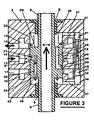
- the apparatus includes a drill head 1 which is positioned above the ground 2 and is suitably supported in a rig (not shown in the drawings) in a manner that will be apparent to those skilled in the art.
- the drill head includes a cylinder chamber 3 on which a ballast weight 4 is mounted.
- a work piston 5 has reciprocating longitudinal movement within the bore of the cylinder chamber 3 and the piston 5 is connected to a piston shaft 6 which is guided at a first end 6a in a sleeve 4a formed in the ballast weight 4.
- a suitable fluid seal 8 is located in the sleeve 4a to ensure an adequate seal between the bore of the cylinder chamber 3 and ambient.
- the second end 6a of the piston shaft 6 extends through a seal 9 located in an end plate 10 of the cylinder chamber 3 to enable the bore of the chamber below the piston 5 to be sealed from ambient.
- the piston shaft may be hollow to facilitate the sampling of cores as will be known in the art.
- the piston shaft 6 bears on or forms part of a mandrel 11 or a drill string which as illustrated is partly embedded in the ground 2.
- Means (not shown in the drawings) as will be apparent to those skilled in the art may also be provided to rotate the drill string or mandrel to ensure the integrity of any screwed joints that may be employed in the drill string, and also to facilitate the disassembly of the drill string and the controlled guidance of the drill string during operation.
- the cylinder chamber 3 includes an inlet gallery 12 having an inlet port 13 to which a source of high pressure fluid can be connected.
- the cylinder chamber also includes a first exhaust gallery 14 having an outlet port 15 and a second exhaust gallery 16 having an outlet port 17.
- the work piston 5 includes a first transfer gallery 20 which can communicate with an opening 21 in the axial face of the piston 5 and which extends longitudinally through the piston to exit at 22 in the land 23 of the work piston. As illustrated, the opening 21 is offset from the longitudinal center of the piston.
- the piston also includes a second transfer gallery 25, one end of which is open at 26 through a port 30 in the axial wall of the piston with the other end being open at 27 in the land 28 of the piston.
- the opening 26 of the second transfer gallery 25 is offset from the longitudinal center of the piston an equivalent but opposite amount of distance to that of the opening 21.
- the apparatus also includes a fluid by pass which in a highly preferred form comprises a bore 36 formed longitudinally in the cylinder and which communicates via a duct 37 with the cylinder chamber 38 both above and below the piston 5.
- a reciprocating by pass piston 40 has free longitudinal movement within the bore 36 and suitable fluid seals 41 are located at either end of the piston 40 to prevent the passage of fluid past the seals.
- fluid under pressure is ducted to the port 13 and passes into the inlet gallery 12 which preferably extends 360° around the cylinder wall.
- the pressurized fluid will pass into the first transfer gallery 20 as indicated by the arrows and exit through the opening 22 in the axial face of the piston into the chamber 38.
- the exhaust ports to the gallery 17 are closed while the exhaust ports to the gallery 14 are open so that the interior of the chamber above the piston is open to the gallery 14. It will be noted that at all times the chamber 38 both above and below the piston remain open to the ducts 37 and consequently to the bore 36.
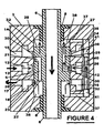
- the opening 26 of the second transfer gallery 25 will commence to register with the inlet gallery 12 and fluid under pressure will flow through the second transfer gallery. 25 and out of the opening 27 in the land 28 of the piston into the chamber 38 above the piston.
- the upward movement of the piston will continue until the piston reaches the position illustrated in Figure 4 , at which stage the pressure of the fluid entering the cylinder chamber 38 via the opening 27 in the second transfer duct 25 will commence to force the piston back into the second cycle of the operation.
- the preferred form of fluid will generally be hydraulic or similar oil, but the fluid can also be a gas such as air or steam which is supplied at an appropriate volume and pressure by any known pressure generating system.
- One such pressure generating system can for instance be a form of internal combustion engine.
Landscapes
- Engineering & Computer Science (AREA)
- Geology (AREA)
- Mining & Mineral Resources (AREA)
- Life Sciences & Earth Sciences (AREA)
- General Life Sciences & Earth Sciences (AREA)
- Fluid Mechanics (AREA)
- Environmental & Geological Engineering (AREA)
- Physics & Mathematics (AREA)
- Geochemistry & Mineralogy (AREA)
- Mechanical Engineering (AREA)
- Earth Drilling (AREA)
- Actuator (AREA)
- Perforating, Stamping-Out Or Severing By Means Other Than Cutting (AREA)
- Percussive Tools And Related Accessories (AREA)
- Drilling Tools (AREA)
- Drilling And Boring (AREA)
- Pistons, Piston Rings, And Cylinders (AREA)
Claims (10)
- Dispositif pour générer des ondes de pression sinusoïdales pour application à un train de tiges de forage (11), ledit dispositif comprenant :un cylindre comportant une chambre (3) qui possède un alésage, une voie d'entrée (12) et une voie d'évacuation (14) ;un piston de travail (5), prévu pour se déplacer selon un mouvement alternatif dans l'alésage de la chambre (3) et ayant une paroi radiale pour assurer l'étanchéité contre la paroi de l'alésage de la chambre pendant le mouvement alternatif à l'intérieur de la chambre (3), un premier méplat (28) à une extrémité du piston de travail et un deuxième méplat (23) là deuxième extrémité du piston de travail ;des moyens pour, canaliser un fluide sous pression de la voie d'entrée (12) jusque dans l'alésage du cylindre au-dessus du premier méplat (28) du piston de travail et le faire ressortir de l'alésage au-dessous du deuxième méplat (23) du piston en passaut dans la voie d'évacuation (14) pour déplacer le piston de travail (5) dans l'alésage, et pour canaliser un fluide sous pression de la voie d'entrée (12) dans l'alésage du cylindre au-dessous du deuxième méplat (23) du piston et le faire ressortir de l'alésage au-dessus du premier méplat (28) du piston en passant dans la voie d'évacuation (14) pour déplacer le piston (5) dans l'alésage ; etun arbre (6) de piston, relié au piston de travail (5) et destiné à transmettre les forces générées par le mouvement alternatif du piston au train de tiges de forage (11) ;caractérisé en ce quela chambre (3) comprend un alésage de décharge (36) ayant une première extrémité ouverte sur l'alésage du cylindre au-dessus de la première face radiale du piston de travail (5) et ayant une deuxième extrémité ouverte sur l'alésage du cylindre au-dessous de la deuxième face radiale du piston de travail (5), ledit alésage de décharge comprenant un piston de décharge alternatif (40) apte à un mouvement alternatif dans l'alésage de décharge et à assurer l'étanchéité contre la paroi de l'alésage de décharge pendant son mouvement alternatif, et dont le mouvement est déterminé par le mouvement du fluide entrant et sortant de l'alésage de décharge en provenance de la chambre du cylindre.
- Dispositif selon la revendication 1, dans lequel chaque voie d'entrée (12) du piston (5) possède un orifice d'entrée (13) pour permettre à un fluide sous pression de pénétrer dans la voie (12), ladite voie d'entrée communiquant avec l'alésage du cylindre par un orifice qui aboutit à la surface de la paroi de l'alésage.
- Dispositif selon la revendication 1, possédant : une première dérivation de décharge (37) qui communique avec une portion de l'alésage du cylindre à une extrémité du piston de travail et avec l'alésage de décharge à une extrémité du piston de décharge ; et
une deuxième dérivation de décharge (37) qui communique avec une portion de l'alésage du cylindre à la deuxième extrémité du piston de travail et qui communique, avec l'alésage de décharge à la deuxième extrémité du piston de décharge ;
la construction et l'agencement étant tels que, quand le piston de travail se déplace dans une direction à l'intérieur de l'alésage du cylindre, le fluide dans l'alésage à une première extrémité du cylindre sera forcé, via la première dérivation de décharge (37), dans la première extrémité de l'alésage de décharge, à déplacer le piston de décharge (40) dans l'alésage de décharge (36) pour mettre sous pression le fluide dans la deuxième extrémité de l'alésage de décharge et à déplacer le fluide, via la deuxième dérivation de décharge (37), dans la deuxième extrémité de l'alésage du cylindre. - Dispositif selon la revendication 1, dans lequel chaque voie d'entrée (12) s'étend sur 360° autour de la paroi de la chambre,
- Dispositif selon la revendication 1, dans lequel le corps du piston de travail comprend une première voie de transfert (20) s'étendant longitudinalement à travers le corps et communiquant via la paroi radiale du piston de travail avec ladite voie d'entrée (12) pendant une durée prédéterminée pendant le mouvement alternatif du piston de travail (5) et communiquant aussi avec l'alésage du cylindre via la première face radiale du piston de travail
- Dispositif selon la revendication 1, dans lequel le corps du piston de travail comprend une deuxième voie de transfert (25) s'étendant longitudinalement à le corps et communiquant via la paroi radiale du piston de travail (5) avec ladite voie d'entrée pendant une durée prédéterminée pendant le mouvement alternatif du piston de travail et communiquant aussi avec l'alésage du cylindre via la deuxième face radiale du piston de travail.
- Dispositif pour générer des ondes de pression sinusoïdales pour application à un train de tiges de forage selon la revendication 1, dans lequel la chambre comprend deux voies d'évacuation,
la première voie d'évacuation (14) communiquant avec la chambre du cylindre au-dessus de la première face radiale du piston de travail, et
la deuxième voie d'évacuation (16) communiquant avec l'alésage du cylindre au-dessous de la deuxième face radiale du piston de travail,
la première et la deuxième voies d'évacuation comportant des orifices de sortie (15, 17) pour permettre au fluide situé dans les voies d'être évacué de l'alésage du cylindre. - Dispositif pour générer des ondes de pression sinusoïdales pour application à un train de tiges de forage selon la revendication 1, dans lequel l'emplacement de l'ouverture de la première voie de transfert (20) dans la paroi radiale du piston de travail est décalé longitudinalement par rapport à l'ouverture de la deuxième voie de transfert (25) dans la paroi radiale du piston de travail.
- Dispositif pour générer des ondes de pression pour application à un train de tiges de forage selon la revendication 1, dans lequel le cylindre est supporté par
une installation de forage et le piston de travail comprend un arbre (16) de piston qui peut être raccordé au train de tiges de forage. - Dispositif pour générer des ondes de pression sinusoïdales pour application à un train de tiges de forage selon la revendication 1, dans lequel la chambre du cylindre fait partie d'une tête de forage qui comprend une masse d'alourdissement.
Applications Claiming Priority (3)
| Application Number | Priority Date | Filing Date | Title |
|---|---|---|---|
| NZ516798A NZ516798A (en) | 2002-07-24 | 2002-07-24 | Sonic drilling |
| NZ51679802 | 2002-07-24 | ||
| PCT/NZ2003/000158 WO2004009298A1 (fr) | 2002-07-24 | 2003-07-23 | Appareil de forage ultrasonore |
Publications (3)
| Publication Number | Publication Date |
|---|---|
| EP1545839A1 EP1545839A1 (fr) | 2005-06-29 |
| EP1545839A4 EP1545839A4 (fr) | 2008-12-17 |
| EP1545839B1 true EP1545839B1 (fr) | 2011-04-06 |
Family
ID=30768275
Family Applications (1)
| Application Number | Title | Priority Date | Filing Date |
|---|---|---|---|
| EP03741702A Expired - Lifetime EP1545839B1 (fr) | 2002-07-24 | 2003-07-23 | Appareil de forage sonique |
Country Status (11)
| Country | Link |
|---|---|
| US (1) | US7234537B2 (fr) |
| EP (1) | EP1545839B1 (fr) |
| JP (1) | JP4647999B2 (fr) |
| CN (1) | CN100404209C (fr) |
| AT (1) | ATE504400T1 (fr) |
| AU (1) | AU2003281473B2 (fr) |
| CA (1) | CA2493039A1 (fr) |
| DE (1) | DE60336665D1 (fr) |
| HK (1) | HK1081904A1 (fr) |
| NZ (1) | NZ516798A (fr) |
| WO (1) | WO2004009298A1 (fr) |
Families Citing this family (11)
| Publication number | Priority date | Publication date | Assignee | Title |
|---|---|---|---|---|
| DE102004042369A1 (de) * | 2004-09-01 | 2006-07-13 | Eurodrill Gmbh | Bodenbearbeitungsgerät und Verfahren zum Einbringen eines Arbeitselementes in den Boden |
| AR051573A1 (es) * | 2004-09-22 | 2007-01-24 | Sds Digger Tools Pty Ltd | Diseno de piston para martillo de fondo |
| CN101107417B (zh) * | 2004-12-14 | 2013-07-17 | 柔性钻井有限公司 | 振动设备 |
| EP1728564B1 (fr) | 2005-05-30 | 2010-04-07 | Klemm Bohrtechnik GmbH | Générateur de vibrations avec un piston coulissant monté entre des chambres de pression |
| EA016010B1 (ru) * | 2006-06-09 | 2012-01-30 | Юниверсити Корт Ов Де Юниверсити Ов Абердин | Способ и устройство бурения |
| US7740088B1 (en) | 2007-10-30 | 2010-06-22 | The United States Of America As Represented By The Administrator Of The National Aeronautics And Space Administration | Ultrasonic rotary-hammer drill |
| US8925648B2 (en) * | 2008-05-29 | 2015-01-06 | Peter A. Lucon | Automatic control of oscillatory penetration apparatus |
| KR101373544B1 (ko) * | 2012-07-03 | 2014-03-25 | 이일재 | 유압타격장치용 타격몸체 |
| CN103195386B (zh) * | 2013-04-11 | 2015-11-04 | 河南省泓森石油技术开发有限公司 | 井下双波低频大功率水力振动器 |
| EP3023199B1 (fr) | 2014-11-20 | 2019-02-27 | Sandvik Mining and Construction Oy | Piston à percussion et méthode d'utilisation |
| KR101889367B1 (ko) * | 2016-10-31 | 2018-08-17 | 이경운 | 양로드 진동장치를 구비한 진동이송기 |
Family Cites Families (28)
| Publication number | Priority date | Publication date | Assignee | Title |
|---|---|---|---|---|
| US2763060A (en) * | 1952-07-28 | 1956-09-18 | Bernard A Swanson | Fluid pressure operated reciprocatory vibratory sheet material cutting shears |
| US2821962A (en) * | 1953-11-06 | 1958-02-04 | Bernard A Swanson | Engines |
| US3375884A (en) | 1965-08-16 | 1968-04-02 | Albert G. Bodine Jr. | Sonic method and apparatus for driving casings through earthen formations |
| US3379263A (en) | 1966-02-01 | 1968-04-23 | Albert G. Bodine Jr. | Sonic method and apparatus for installing pile member, casing members or the like, in earthen formations |
| US3680442A (en) * | 1970-11-05 | 1972-08-01 | Ben C Klingensmith | Gas pressure driven vibratory cylinder construction |
| US3736843A (en) * | 1971-05-20 | 1973-06-05 | Applied Power Ind Inc | Vibrator apparatus |
| JPS5819436B2 (ja) * | 1977-07-11 | 1983-04-18 | 東京流機製造株式会社 | 2段ピストン機構とそれに連動するコントロ−ルバルブを内装する油圧ブレ−カ−又は油圧さく岩機 |
| DE2917830A1 (de) * | 1979-05-03 | 1980-11-06 | Tuenkers Maschinenbau Gmbh | Hydraulischer impulsvibrationsbaer |
| JPS6015833Y2 (ja) * | 1979-06-01 | 1985-05-17 | マツダ株式会社 | 油圧打撃工具における打撃ピストンの往復切換装置 |
| US4527637A (en) | 1981-05-11 | 1985-07-09 | Bodine Albert G | Cycloidal drill bit |
| JPS5833065B2 (ja) * | 1979-11-16 | 1983-07-16 | 三菱重工業株式会社 | 油圧打撃装置 |
| JPS597570A (ja) * | 1982-07-05 | 1984-01-14 | 北越工業株式会社 | 油圧作動衝撃工具 |
| JPS63144179U (fr) * | 1987-03-12 | 1988-09-22 | ||
| US4836299A (en) | 1987-10-19 | 1989-06-06 | Bodine Albert G | Sonic method and apparatus for installing monitor wells for the surveillance and control of earth contamination |
| JPH0639796Y2 (ja) * | 1990-05-18 | 1994-10-19 | チャオ チン ライ | 破砕機本体の構造 |
| US5234056A (en) * | 1990-08-10 | 1993-08-10 | Tri-State Oil Tools, Inc. | Sonic method and apparatus for freeing a stuck drill string |
| CA2058659C (fr) * | 1991-01-08 | 2001-02-20 | Michael Richard Davies | Actionneur hydraulique a action cyclique |
| FR2676953B1 (fr) * | 1991-05-30 | 1993-08-20 | Montabert Ets | Appareil hydraulique a percussions. |
| US5209564A (en) * | 1992-01-21 | 1993-05-11 | National Air Vibrator Company | Vibrator |
| US5417290A (en) | 1994-09-02 | 1995-05-23 | Water Development Technologies, Inc. | Sonic drilling method and apparatus |
| US5562169A (en) | 1994-09-02 | 1996-10-08 | Barrow; Jeffrey | Sonic Drilling method and apparatus |
| JPH08281571A (ja) * | 1995-04-14 | 1996-10-29 | Komatsu Ltd | 振動発生装置 |
| US5549170A (en) * | 1995-04-27 | 1996-08-27 | Barrow; Jeffrey | Sonic drilling method and apparatus |
| US5806608A (en) * | 1997-02-14 | 1998-09-15 | Dubois; Johnny | Air-driven post driver |
| US6378951B1 (en) * | 1997-07-23 | 2002-04-30 | Hydroacoustics, Inc. | Vibratory pavement breaker |
| FI107891B (fi) * | 1998-03-30 | 2001-10-31 | Sandvik Tamrock Oy | Painenestekäyttöinen iskulaite |
| US6338390B1 (en) * | 1999-01-12 | 2002-01-15 | Baker Hughes Incorporated | Method and apparatus for drilling a subterranean formation employing drill bit oscillation |
| US6863136B2 (en) | 2000-05-03 | 2005-03-08 | Yoseph Bar-Cohen | Smart-ultrasonic/sonic driller/corer |
-
2002
- 2002-07-24 NZ NZ516798A patent/NZ516798A/en not_active IP Right Cessation
-
2003
- 2003-07-23 AT AT03741702T patent/ATE504400T1/de not_active IP Right Cessation
- 2003-07-23 AU AU2003281473A patent/AU2003281473B2/en not_active Ceased
- 2003-07-23 EP EP03741702A patent/EP1545839B1/fr not_active Expired - Lifetime
- 2003-07-23 US US10/522,104 patent/US7234537B2/en not_active Expired - Fee Related
- 2003-07-23 CA CA002493039A patent/CA2493039A1/fr not_active Abandoned
- 2003-07-23 CN CNB038200333A patent/CN100404209C/zh not_active Expired - Fee Related
- 2003-07-23 WO PCT/NZ2003/000158 patent/WO2004009298A1/fr active Application Filing
- 2003-07-23 DE DE60336665T patent/DE60336665D1/de not_active Expired - Lifetime
- 2003-07-23 JP JP2004522864A patent/JP4647999B2/ja not_active Expired - Fee Related
-
2006
- 2006-02-17 HK HK06102091.8A patent/HK1081904A1/xx not_active IP Right Cessation
Also Published As
| Publication number | Publication date |
|---|---|
| US20060162961A1 (en) | 2006-07-27 |
| HK1081904A1 (en) | 2006-05-26 |
| JP2005533665A (ja) | 2005-11-10 |
| US7234537B2 (en) | 2007-06-26 |
| AU2003281473A1 (en) | 2004-02-09 |
| CN1678432A (zh) | 2005-10-05 |
| CA2493039A1 (fr) | 2004-01-29 |
| NZ516798A (en) | 2004-07-30 |
| WO2004009298A1 (fr) | 2004-01-29 |
| EP1545839A1 (fr) | 2005-06-29 |
| AU2003281473B2 (en) | 2008-05-08 |
| CN100404209C (zh) | 2008-07-23 |
| DE60336665D1 (de) | 2011-05-19 |
| EP1545839A4 (fr) | 2008-12-17 |
| JP4647999B2 (ja) | 2011-03-09 |
| ATE504400T1 (de) | 2011-04-15 |
Similar Documents
| Publication | Publication Date | Title |
|---|---|---|
| US3532174A (en) | Vibratory drill apparatus | |
| EP1545839B1 (fr) | Appareil de forage sonique | |
| EP0245892B1 (fr) | Dispositif pour faire vibrer un train de tiges dans un puits | |
| AU2012226479B2 (en) | Mechanical force generator for a downhole excitation apparatus | |
| US20060225922A1 (en) | Vibrational heads and assemblies and uses thereof | |
| US5351754A (en) | Apparatus and method to cause fatigue failure of subterranean formations | |
| JP5509095B2 (ja) | 脈動発生装置及びかかる装置を備えた削岩装置 | |
| KR20070086636A (ko) | 진동장치 | |
| GB2129559A (en) | Down hole periodic seismic signal generator | |
| WO2020214062A1 (fr) | Dispositif de génération de charge axiale dans la composition d'une colonne de forage | |
| US4068595A (en) | Track tamper | |
| JP2005533665A5 (fr) | ||
| CA1051268A (fr) | Ballastiere et mecanisme vibratoire de commande | |
| US7810618B2 (en) | Vibration generator | |
| US4092903A (en) | Vibratory drive mechanism | |
| WO2005087393A1 (fr) | Tetes et ensembles a vibrations et utilisations associees | |
| NZ531833A (en) | Vibration head, typically for drill string, with shuttle moving rectilinearly and transferring vibration via complementary member | |
| AU2008200807A1 (en) | Sonic Heads and Asemblies and Uses Thereof | |
| NZ526639A (en) | Vibrational apparatus for drilling with rotary valve to control movement of shuttle | |
| MXPA05013999A (en) | Sonic heads and assemblies and uses thereof | |
| SU321624A1 (ru) | Погружной вибробур | |
| JPS6363762B2 (fr) |
Legal Events
| Date | Code | Title | Description |
|---|---|---|---|
| PUAI | Public reference made under article 153(3) epc to a published international application that has entered the european phase |
Free format text: ORIGINAL CODE: 0009012 |
|
| 17P | Request for examination filed |
Effective date: 20050217 |
|
| AK | Designated contracting states |
Kind code of ref document: A1 Designated state(s): AT BE BG CH CY CZ DE DK EE ES FI FR GB GR HU IE IT LI LU MC NL PT RO SE SI SK TR |
|
| AX | Request for extension of the european patent |
Extension state: AL LT LV MK |
|
| DAX | Request for extension of the european patent (deleted) | ||
| A4 | Supplementary search report drawn up and despatched |
Effective date: 20081118 |
|
| RIC1 | Information provided on ipc code assigned before grant |
Ipc: E21B 4/14 20060101ALI20081113BHEP Ipc: E21B 7/24 20060101ALI20081113BHEP Ipc: E21B 1/30 20060101ALI20081113BHEP Ipc: E21B 1/26 20060101ALI20081113BHEP Ipc: E21B 1/24 20060101ALI20081113BHEP Ipc: B25D 9/04 20060101ALI20081113BHEP Ipc: B25D 9/02 20060101AFI20040211BHEP |
|
| 17Q | First examination report despatched |
Effective date: 20090518 |
|
| GRAP | Despatch of communication of intention to grant a patent |
Free format text: ORIGINAL CODE: EPIDOSNIGR1 |
|
| GRAJ | Information related to disapproval of communication of intention to grant by the applicant or resumption of examination proceedings by the epo deleted |
Free format text: ORIGINAL CODE: EPIDOSDIGR1 |
|
| GRAP | Despatch of communication of intention to grant a patent |
Free format text: ORIGINAL CODE: EPIDOSNIGR1 |
|
| GRAS | Grant fee paid |
Free format text: ORIGINAL CODE: EPIDOSNIGR3 |
|
| GRAA | (expected) grant |
Free format text: ORIGINAL CODE: 0009210 |
|
| AK | Designated contracting states |
Kind code of ref document: B1 Designated state(s): AT BE BG CH CY CZ DE DK EE ES FI FR GB GR HU IE IT LI LU MC NL PT RO SE SI SK TR |
|
| REG | Reference to a national code |
Ref country code: GB Ref legal event code: FG4D |
|
| REG | Reference to a national code |
Ref country code: CH Ref legal event code: EP |
|
| REG | Reference to a national code |
Ref country code: IE Ref legal event code: FG4D |
|
| REF | Corresponds to: |
Ref document number: 60336665 Country of ref document: DE Date of ref document: 20110519 Kind code of ref document: P |
|
| REG | Reference to a national code |
Ref country code: DE Ref legal event code: R096 Ref document number: 60336665 Country of ref document: DE Effective date: 20110519 |
|
| REG | Reference to a national code |
Ref country code: NL Ref legal event code: VDEP Effective date: 20110406 |
|
| PGFP | Annual fee paid to national office [announced via postgrant information from national office to epo] |
Ref country code: IE Payment date: 20110629 Year of fee payment: 9 |
|
| PG25 | Lapsed in a contracting state [announced via postgrant information from national office to epo] |
Ref country code: SI Free format text: LAPSE BECAUSE OF FAILURE TO SUBMIT A TRANSLATION OF THE DESCRIPTION OR TO PAY THE FEE WITHIN THE PRESCRIBED TIME-LIMIT Effective date: 20110406 |
|
| PG25 | Lapsed in a contracting state [announced via postgrant information from national office to epo] |
Ref country code: PT Free format text: LAPSE BECAUSE OF FAILURE TO SUBMIT A TRANSLATION OF THE DESCRIPTION OR TO PAY THE FEE WITHIN THE PRESCRIBED TIME-LIMIT Effective date: 20110808 Ref country code: SE Free format text: LAPSE BECAUSE OF FAILURE TO SUBMIT A TRANSLATION OF THE DESCRIPTION OR TO PAY THE FEE WITHIN THE PRESCRIBED TIME-LIMIT Effective date: 20110406 |
|
| PGFP | Annual fee paid to national office [announced via postgrant information from national office to epo] |
Ref country code: FR Payment date: 20110729 Year of fee payment: 9 |
|
| PG25 | Lapsed in a contracting state [announced via postgrant information from national office to epo] |
Ref country code: ES Free format text: LAPSE BECAUSE OF FAILURE TO SUBMIT A TRANSLATION OF THE DESCRIPTION OR TO PAY THE FEE WITHIN THE PRESCRIBED TIME-LIMIT Effective date: 20110717 Ref country code: FI Free format text: LAPSE BECAUSE OF FAILURE TO SUBMIT A TRANSLATION OF THE DESCRIPTION OR TO PAY THE FEE WITHIN THE PRESCRIBED TIME-LIMIT Effective date: 20110406 Ref country code: BE Free format text: LAPSE BECAUSE OF FAILURE TO SUBMIT A TRANSLATION OF THE DESCRIPTION OR TO PAY THE FEE WITHIN THE PRESCRIBED TIME-LIMIT Effective date: 20110406 Ref country code: CY Free format text: LAPSE BECAUSE OF FAILURE TO SUBMIT A TRANSLATION OF THE DESCRIPTION OR TO PAY THE FEE WITHIN THE PRESCRIBED TIME-LIMIT Effective date: 20110406 Ref country code: GR Free format text: LAPSE BECAUSE OF FAILURE TO SUBMIT A TRANSLATION OF THE DESCRIPTION OR TO PAY THE FEE WITHIN THE PRESCRIBED TIME-LIMIT Effective date: 20110707 Ref country code: AT Free format text: LAPSE BECAUSE OF FAILURE TO SUBMIT A TRANSLATION OF THE DESCRIPTION OR TO PAY THE FEE WITHIN THE PRESCRIBED TIME-LIMIT Effective date: 20110406 |
|
| PGFP | Annual fee paid to national office [announced via postgrant information from national office to epo] |
Ref country code: GB Payment date: 20110721 Year of fee payment: 9 Ref country code: DE Payment date: 20110722 Year of fee payment: 9 |
|
| PG25 | Lapsed in a contracting state [announced via postgrant information from national office to epo] |
Ref country code: NL Free format text: LAPSE BECAUSE OF FAILURE TO SUBMIT A TRANSLATION OF THE DESCRIPTION OR TO PAY THE FEE WITHIN THE PRESCRIBED TIME-LIMIT Effective date: 20110406 |
|
| PG25 | Lapsed in a contracting state [announced via postgrant information from national office to epo] |
Ref country code: EE Free format text: LAPSE BECAUSE OF FAILURE TO SUBMIT A TRANSLATION OF THE DESCRIPTION OR TO PAY THE FEE WITHIN THE PRESCRIBED TIME-LIMIT Effective date: 20110406 Ref country code: CZ Free format text: LAPSE BECAUSE OF FAILURE TO SUBMIT A TRANSLATION OF THE DESCRIPTION OR TO PAY THE FEE WITHIN THE PRESCRIBED TIME-LIMIT Effective date: 20110406 |
|
| PLBE | No opposition filed within time limit |
Free format text: ORIGINAL CODE: 0009261 |
|
| STAA | Information on the status of an ep patent application or granted ep patent |
Free format text: STATUS: NO OPPOSITION FILED WITHIN TIME LIMIT |
|
| PG25 | Lapsed in a contracting state [announced via postgrant information from national office to epo] |
Ref country code: DK Free format text: LAPSE BECAUSE OF FAILURE TO SUBMIT A TRANSLATION OF THE DESCRIPTION OR TO PAY THE FEE WITHIN THE PRESCRIBED TIME-LIMIT Effective date: 20110406 Ref country code: MC Free format text: LAPSE BECAUSE OF NON-PAYMENT OF DUE FEES Effective date: 20110731 Ref country code: RO Free format text: LAPSE BECAUSE OF FAILURE TO SUBMIT A TRANSLATION OF THE DESCRIPTION OR TO PAY THE FEE WITHIN THE PRESCRIBED TIME-LIMIT Effective date: 20110406 Ref country code: SK Free format text: LAPSE BECAUSE OF FAILURE TO SUBMIT A TRANSLATION OF THE DESCRIPTION OR TO PAY THE FEE WITHIN THE PRESCRIBED TIME-LIMIT Effective date: 20110406 |
|
| REG | Reference to a national code |
Ref country code: CH Ref legal event code: PL |
|
| 26N | No opposition filed |
Effective date: 20120110 |
|
| PG25 | Lapsed in a contracting state [announced via postgrant information from national office to epo] |
Ref country code: LI Free format text: LAPSE BECAUSE OF NON-PAYMENT OF DUE FEES Effective date: 20110731 Ref country code: CH Free format text: LAPSE BECAUSE OF NON-PAYMENT OF DUE FEES Effective date: 20110731 |
|
| REG | Reference to a national code |
Ref country code: DE Ref legal event code: R097 Ref document number: 60336665 Country of ref document: DE Effective date: 20120110 |
|
| GBPC | Gb: european patent ceased through non-payment of renewal fee |
Effective date: 20120723 |
|
| REG | Reference to a national code |
Ref country code: FR Ref legal event code: ST Effective date: 20130329 |
|
| PG25 | Lapsed in a contracting state [announced via postgrant information from national office to epo] |
Ref country code: DE Free format text: LAPSE BECAUSE OF NON-PAYMENT OF DUE FEES Effective date: 20130201 Ref country code: FR Free format text: LAPSE BECAUSE OF NON-PAYMENT OF DUE FEES Effective date: 20120731 Ref country code: GB Free format text: LAPSE BECAUSE OF NON-PAYMENT OF DUE FEES Effective date: 20120723 |
|
| REG | Reference to a national code |
Ref country code: IE Ref legal event code: MM4A |
|
| PG25 | Lapsed in a contracting state [announced via postgrant information from national office to epo] |
Ref country code: LU Free format text: LAPSE BECAUSE OF NON-PAYMENT OF DUE FEES Effective date: 20110723 Ref country code: IT Free format text: LAPSE BECAUSE OF NON-PAYMENT OF DUE FEES Effective date: 20120723 |
|
| PG25 | Lapsed in a contracting state [announced via postgrant information from national office to epo] |
Ref country code: BG Free format text: LAPSE BECAUSE OF FAILURE TO SUBMIT A TRANSLATION OF THE DESCRIPTION OR TO PAY THE FEE WITHIN THE PRESCRIBED TIME-LIMIT Effective date: 20110706 |
|
| PG25 | Lapsed in a contracting state [announced via postgrant information from national office to epo] |
Ref country code: IE Free format text: LAPSE BECAUSE OF NON-PAYMENT OF DUE FEES Effective date: 20120723 |
|
| REG | Reference to a national code |
Ref country code: DE Ref legal event code: R119 Ref document number: 60336665 Country of ref document: DE Effective date: 20130201 |
|
| PG25 | Lapsed in a contracting state [announced via postgrant information from national office to epo] |
Ref country code: TR Free format text: LAPSE BECAUSE OF FAILURE TO SUBMIT A TRANSLATION OF THE DESCRIPTION OR TO PAY THE FEE WITHIN THE PRESCRIBED TIME-LIMIT Effective date: 20110406 |
|
| PG25 | Lapsed in a contracting state [announced via postgrant information from national office to epo] |
Ref country code: HU Free format text: LAPSE BECAUSE OF FAILURE TO SUBMIT A TRANSLATION OF THE DESCRIPTION OR TO PAY THE FEE WITHIN THE PRESCRIBED TIME-LIMIT Effective date: 20110406 |