EP1545838B1 - Selbstjustierende gerillte zange - Google Patents
Selbstjustierende gerillte zange Download PDFInfo
- Publication number
- EP1545838B1 EP1545838B1 EP03788313A EP03788313A EP1545838B1 EP 1545838 B1 EP1545838 B1 EP 1545838B1 EP 03788313 A EP03788313 A EP 03788313A EP 03788313 A EP03788313 A EP 03788313A EP 1545838 B1 EP1545838 B1 EP 1545838B1
- Authority
- EP
- European Patent Office
- Prior art keywords
- section
- pivot
- pliers
- self adjusting
- tongue
- Prior art date
- Legal status (The legal status is an assumption and is not a legal conclusion. Google has not performed a legal analysis and makes no representation as to the accuracy of the status listed.)
- Expired - Lifetime
Links
Images





Classifications
-
- B—PERFORMING OPERATIONS; TRANSPORTING
- B25—HAND TOOLS; PORTABLE POWER-DRIVEN TOOLS; MANIPULATORS
- B25B—TOOLS OR BENCH DEVICES NOT OTHERWISE PROVIDED FOR, FOR FASTENING, CONNECTING, DISENGAGING, OR HOLDING
- B25B7/00—Pliers; Other hand-held gripping tools with jaws on pivoted limbs; Details applicable generally to pivoted-limb hand tools
- B25B7/06—Joints
- B25B7/10—Joints with adjustable fulcrum
Definitions
- This invention relates, in particular to grooved pliers, which are self adjusting, according to the preamble of independent claim 1.
- Pliers having jaws which are adjustable between various positions are well known in the art.
- these types of pliers include two halves each having a jaw portion the halves are coupled at a pivot by a bolt or rivet.
- One half includes a channel allowing the pivot to be adjusted by moving the bolt or rivet therealong for a wider or narrower association between the jaw portions of the halves.
- the conventional grooved pliers include a plurality of grooves formed in one half proximate the channel for receiving a tongue formed on the other half. The adjustment is accomplished by opening the pliers fully so that the tongue leaves the grooves, and sliding the two halves until the tongue on one section aligns with the desired groove on the other section.
- pliers having adjustable jaws and comprising a first leg having an elongate slot which receives a pivot pin fixed to a second leg. Each leg has a jaw and the pin is slidable in the slot to adjust the jaws relative to one another.
- the first leg further comprises a plurality of arcuate notches which are shaped to receive an arcuate rib on the second leg which can be engaged in a selected one of the notches, in which position movement along the slot is prevented but pivotal operating movement is allowed.
- Another object of the present invention is to provide grooved pliers which can be adjusted with one hand.
- Yet another object of the present invention is to provide adjustable grooved pliers which can be adjusted while engaging an object.
- self adjusting grooved pliers which include a first section having a jaw portion and a channel formed therethrough adjacent the jaw portion and a second section having a jaw portion and a pivot extending therefrom.
- the pivot is slidably received in the channel to allow wider or narrower association between the jaw portion of the first section and the jaw portion of the second section.
- the pivot pivotally couples the first section to the second section for movement between an open position and a gripping position.
- a plurality of grooves is formed in the first section and a tongue extends from the second section. The tongue is received in one of the plurality of grooves, locking the pivot in position within the channel only upon the first section and the second section reaching the gripping position.
- a biasing assembly acts on the pivot, urging the pivot upward in the channel toward the jaw portion of the first section.
- the biasing assembly includes a coil spring fitted into a handle portion of the first section and an extension member having an end engaging the coil spring and an opposing end extending into the channel and engaging the pivot.
- the coil spring and the extension cooperate to urge the pivot in the channel toward the first jaw portion.
- the biasing assembly includes a post extending from the pivot into a receptacle extending from the first section and a coil spring carried by the post within the receptacle. The compression spring is compressed between the pivot and the receptacle.
- the second jaw portion of the second section is carried by a jaw element pivotally coupled to the second section.
- the jaw element is movable between a start position and a finish position, and is biased into the start position by a biasing member.
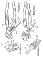
- FIG. 1 illustrates self adjusting grooved pliers generally designated 10.
- Pliers 10 are similar to conventional grooved pliers with the exception that modifications have been made to the grooves and tongues, as will be described presently, and a biasing mechanism has been added, which while advantageous, is not required.
- Pliers 10 include a section 12 having a jaw portion 13 and a section 14 having a jaw portion 15, coupled at a pivot 16.
- Section 12 includes a channel 18 adjacent jaw portion 13, which receives pivot 16, allowing pivot 16 between sections 12 and 14, to be adjusted for a wider or narrower association between jaw portions 13 and 15.
- section 12 and section 14 pivot about pivot 16 moving jaw portions 14 and 15 between an open position and a gripping position.
- Conventional grooved pliers include a plurality of grooves formed in one section proximate the channel for receiving a tongue formed on the other section. The adjustment is accomplished by opening the pliers fully so that the tongue leaves the grooves, and sliding the two sections until the tongue on one section aligns with the desired groove on the other section. When the conventional pliers are closed a slight amount, the tongue enters the groove and is locked into that adjustment, preventing movement of the pivot in the channel until the sections are fully opened again.
- Pliers 10 of the present invention includes grooves 20 formed in section 12 proximate channel 18 for receiving a tongue 22 formed on section 14.
- Tongue 22 is shortened to a tooth or nub when compared to existing grooved pliers tongues. Additionally, the positioning of tongue 22 is such that it enters one of grooves 20 slightly before or when jaws 13 and 15 come to a substantially parallel position with respect to one another. It will be understood by one skilled in the art that while tongue 22 is shortened in this preferred embodiment, it may be positioned in a radial position with respect to pivot 16 that the same effect occurs. By positioning tongue 22 in this manner, pliers 10 become self adjusting.
- Closing jaws 13 and 15 about an item to be engaged allows pivot 16 to travel along channel 18 until jaws 13 and 15 are substantially parallel (a preferred gripping position), at which point tongue 22 enter one of grooves 20, locking sections 12 and 14 in position and allowing the application of a clamping force to jaws 13 and 15.
- a preferred gripping position is when jaws 13 and 15 are parallel, or within a few degrees thereof, other gripping position can be employed.
- the gripping position can diverge from parallel by a few degrees or by many degrees as desired, as long as the gripping position is less than a fully open position.
- a biasing assembly can be included which acts on pivot 16, urging it upward in channel 18, toward jaw 13 and into the smallest adjustment distance between jaws 13 and 15.
- the biasing assembly includes a coil spring 24 fitted into a handle portion 25 of section 12 and an extension member 26.
- Extension member 26 is preferably formed of a spring material such as steel or plastic and has an end 28 engaging coil spring 24 and an opposing end 29 extending into channel 18 and engaging pivot 16.
- Coil spring 24 and extension cooperate to urge pivot 16 in channel 18 toward jaw 13.
- jaws 13 and 15 are in the closest or smallest setting.
- jaws 13 and 15 Since the ideal gripping position of jaws 13 and 15 are when they are parallel, it is desirable that jaws 13 and 15 be spread apart a greater distance for larger items.
- the jaws When a larger item is clamped, the jaws are opened sufficiently to engage substantially opposing sides thereof. As the jaws are drawn together by the closing of section 12 and 14, pivot 16 slides back in channel 18 away from jaw 13 against the bias, until jaws 13 and 15 are substantially parallel or slightly before. At this point, by the positioning of tongue 22, tongue 22 enters an aligned one of grooves 20, locking sections 12 and 14 into position and permitting a clamping force to be applied by jaws 13 and 15 to the item being clamped. When pliers 10 is removed from engagement with the item clamped, the biasing assembly urges pivot upward in channel 18 with jaws 13 and 15 in the closest or smallest adjustment prior to the next clamping operation.
- grooves 20 are formed by a plurality of raised ridges 30 each having a leading edge 32 and a slanted leading face 33 slanting back therefrom.
- Tongue 22 also has a leading edge 35 and a slanted leading face 36 slanting back therefrom.
- Leading faces 32 and 34 act in concert as a centering mechanism. When leading edge 35 engages slanted leading face 33, tongue 22 is guided into the adjacent lower groove. When leading edge 33 of tongue 22 engages slanted leading face 36, tongue 22 is guided into an upper adjacent groove. In this manner, pliers 10 will always close smoothly without the need to manually align tongue 22 with one of grooves 20.
- FIG. 5 another embodiment of a pair of pliers generally designated 40 is illustrated.
- Pliers 40 are substantially similar to pliers 10, including a section 42 having a channel therein, a section 43 and a pivot 44.
- the biasing assembly includes a post 45 extending from pivot 44 into a receptacle 46 extending from section 42.
- Post 45 is carried within a coil spring 47 which is compressed between pivot 44 and receptacle 46.
- FIG. 6 a receptacle 46 is illustrated with an open end.
- FIGS. 7 and 8 another embodiment of a self adjusting grooved pliers generally designated 50, is illustrated.
- Pliers 50 are similar to pliers 10, including a section 52 having a jaw portion 53 and a section 54 having a jaw portion 55, pivotally coupled at a pivot 56.
- Section 52 includes a channel 58 adjacent jaw portion 53, allowing pivot 56 between sections 52 and 54 to be adjusted for a wider or narrower association between jaw portions 53 and 55.
- Grooves 60 are formed in section 52 proximate channel 58 for receiving a tongue 62 formed on section 54. Tongue 62 is positioned such that it enters one of grooves 60 slightly before or when jaws 53 and 55 come to a substantially parallel position with respect to one another.
- the difference, in this embodiment, is the construction of section 54.
- Section 54 includes jaw portion 55 carried by a jaw element 64 pivotally coupled to section 54 between a start position and a finish position. The movement of jaw element 64 is biased into the start position by a spring 65.
- jaw element 64 provides more distance of travel of sections 52 and 54 after jaws 53 and 55 become parallel.
- pivot 56 moves downward.
- tongue 62 enters one of grooves 60 and prevents further movement of pivot 56 within channel 58.
- section 54 continues rotation as illustrated by arrowed arc A until jaw element 64 reaches the finish position.
- tongue 62 is received further into the one of grooves 60. This provides a stronger and more secure engagement for the application of clamping force to pliers 50.
- FIGS. 11, 12 and 13 yet another embodiment of a self adjusting grooved pliers generally designated 80, is illustrated.
- Pliers 80 are similar to pliers 50, including a section 82 having a jaw portion 83 and a section 84 having a jaw portion 85, pivotally coupled at a pivot 86.
- Section 82 includes a channel 88 adjacent jaw portion 83, allowing pivot 86 between sections 82 and 84 to be adjusted for a wider or narrower association between jaw portions 83 and 85.
- two sets of grooves 90A and 90B are formed in section 87 proximate a leading side top portion of channel 88 and a trailing side bottom portion thereof respectively, for receiving a tongue 92A and a tongue 92B formed on section 84 on substantially opposing sides of pivot 86.
- Tongues 92A and 92B are positioned such that they enter one of grooves 90A and 90B respectively slightly before or when jaws 83 and 85 come to a substantially parallel position with respect to one another.
- the difference, in this embodiment, is the use of a pair of tongues and a pair of grooves to provide added strength to pliers 80.
- section 84 can include jaw portion 85 carried by a jaw element 94 pivotally coupled to section 84 between a start position and a finish position.
- the movement of jaw element 94 is coupled in a manner as shown with pliers 50.
- tongues 92A and 92B enter more deeply into grooves 90A and 90B, providing a stronger and more reliable engagement.
Landscapes
- Engineering & Computer Science (AREA)
- Mechanical Engineering (AREA)
- Gripping Jigs, Holding Jigs, And Positioning Jigs (AREA)
- Folding Of Thin Sheet-Like Materials, Special Discharging Devices, And Others (AREA)
- Cooling, Air Intake And Gas Exhaust, And Fuel Tank Arrangements In Propulsion Units (AREA)
- Clamps And Clips (AREA)
Claims (15)
- Selbstanpassende gerillte Zange (10), umfassend:einen ersten Abschnitt (12) mit einem ersten Backenabschnitt (13) und einem dadurch ausgebildeten Kanal (18) benachbart zum ersten Backenabschnitt (13);einen zweiten Abschnitt (14) mit einem zweiten Backenabschnitt (15) und einem Drehgelenk (16), das sich davon erstreckt und verschiebbar im Kanal (18) aufgenommen wird, um eine breitere oder schmalere Verbindung zwischen dem ersten Backenabschnitt (13) und dem zweiten Backenabschnitt (15) zu ermöglichen, wobei das Drehgelenk (16) den ersten Abschnitt (12) mit dem zweiten Abschnitt (14) zur Bewegung zwischen einer offenen Position und einer Greifposition drehbar verbindet;eine Mehrzahl von Rillen (20), die in einem von dem ersten Abschnitt (12) und dem zweiten Abschnitt (14) ausgebildet ist;eine Zunge (22), die sich vom anderen von dem ersten Abschnitt (12) und dem zweiten Abschnitt (14) erstreckt, wobei die Zunge (22) in einer der Mehrzahl von Rillen (20) aufgenommen wird und das Drehgelenk (16) in Position innerhalb des Kanals (18) sperrt, wenn der erste Abschnitt (12) und der zweite Abschnitt (14) die Greifposition erreichen,
dadurch gekennzeichnet, dass die Zange (10) ferner umfasst:eine Vorspanngruppe, welche auf das Drehgelenk (16) wirkt und das Drehegelenk (16) im Kanal (18) in Richtung des ersten Backenabschnitts (13) nach oben drückt. - Selbstanpassende gerillte Zange (10) nach Anspruch 1, wobei die Zunge (22) so positioniert und bemessen ist, dass sie nur dann in einer der Mehrzahl von Rillen (20) aufgenommen wird, wenn der erste Abschnitt (12) und der zweite Abschnitt (14) die Greifposition erreichen.
- Selbstanpassende gerillte Zange (10) nach Anspruch 1, wobei die Rillen (20) durch eine Mehrzahl von erhöhten Rippen (30) ausgebildet sind, die jeweils eine Vorderkante (32) und eine abgeschrägte Vorderseite (33), die sich davon nach hinten neigt, aufweisen.
- Selbstanpassende gerillte Zange (10) nach Anspruch 3, wobei die Zunge (22) eine Vorderkante (35) und eine abgeschrägte Vorderseite (36), die sich davon nach hinten neigt, aufweist, wobei die Vorderseite (36) der Zunge (22) und die Vorderseite (33) der Rillen als ein Zentriermechanismus zusammenwirken.
- Selbstanpassende gerillte Zange (10) nach Anspruch 1, wobei die Vorspanngruppe eine Spiralfeder (24), die in einen Griffabschnitt (25) des ersten Abschnitts (12) eingebaut ist, und ein Verlängerungselement (26) mit einem Ende (28) umfasst, das in die Spiralfeder (24) eingreift, und einem gegenüberliegenden Ende (29), das sich in den Kanal (18) erstreckt und in das Drehgelenk (15) eingreift, um dadurch mitzuwirken, das Drehgelenk (16) im Kanal (18) in Richtung des ersten Backenabschnitts (13) zu drücken.
- Selbstanpassende gerillte Zange (10) nach Anspruch 5, wobei das Verlängerungselement (26) aus einem Federmaterial gebildet ist.
- Selbstanpassende gerillte Zange (40) nach Anspruch 6, wobei die Vorspanngruppe einen Stab (45), der sich vom Drehgelenk (44) in eine Aufnahme (46) erstreckt, die sich vom ersten Abschnitt (42) erstreckt, und eine Spiralfeder (47) umfasst, die durch den Stab (45) innerhalb der Aufnahme (46) getragen wird, und die Druckfeder (47) zwischen dem Drehgelenk (44) und der Aufnahme (46) zusammengedrückt wird.
- Selbstanpassende gerillte Zange (50) nach Anspruch 1, wobei der zweite Backenabschnitt (55) des zweiten Abschnitts (54) durch ein Backenelement (64) getragen wird, das mit dem zweiten Abschnitt (54) drehbar verbunden ist, das Backenelement (64) zwischen einer Anfangsposition und einer Endposition bewegt werden kann, und das Backenelement (64) durch ein Vorspannelement (65) in die Anfangsposition vorgespannt wird.
- Selbstanpassende gerillte Zange (80) nach Anspruch 2, wobei die Mehrzahl von Rillen (90A, 90B) im ersten Abschnitt (82) ausgebildet ist; und die Zunge (92A, 92B) sich vom zweiten Abschnitt erstreckt.
- Selbstanpassende gerillte Zange (80) nach Anspruch 9, wobei die Rillen (90A, 90B) durch eine Mehrzahl von erhöhten Rippen ausgebildet ist, die jeweils eine Vorderkante und eine abgeschrägte Vorderseite, die sich davon nach hinten neigt, aufweisen.
- Selbstanpassende gerillte Zange (80) nach Anspruch 10, wobei die Zunge (92A, 92B) eine Vorderkante und eine abgeschrägte Vorderseite, die sich davon nach hinten neigt, aufweist, wobei die Vorderseite der Zunge (92A, 92B) und die Vorderseite der Rillen (90A, 90B) als ein Zentriermechanismus zusammenwirken.
- Selbstanpassende gerillte Zange (80) nach Anspruch 9, wobei die Vorspanngruppe eine Spiralfeder, die in einen Griffabschnitt des ersten Abschnitts (82) eingebaut ist, und ein Verlängerungselement mit einem Ende umfasst, das in die Spiralfeder eingreift, und einem gegenüberliegenden Ende, das sich in den Kanal (88) erstreckt und in das Drehgelenk (86) eingreift, um dadurch mitzuwirken, das Drehgelenk (86) im Kanal (88) in Richtung des Backenabschnitts (83) des ersten Abschnitts (82) zu drücken.
- Selbstanpassende gerillte Zange (80) nach Anspruch 12, wobei das Verlängerungselement aus einem Federmaterial gebildet ist.
- Selbstanpassende gerillte Zange (80) nach Anspruch 9, wobei die Vorspanngruppe einen Stab, der sich vom Drehgelenk (86) in eine Aufnahme erstreckt, die sich vom ersten Abschnitt (82) erstreckt, und eine Spiralfeder umfasst, die durch den Stab innerhalb der Aufnahme getragen wird, und die Druckfeder zwischen dem Drehgelenk (86) und der Aufnahme zusammengedrückt wird.
- Selbstanpassende gerillte Zange (80) nach Anspruch 9, wobei der Backenabschnitt (85) des zweiten Abschnitts (84) durch ein Backenelement getragen wird, das mit dem zweiten Abschnitt (84) drehbar verbunden ist, das Backenelement zwischen einer Anfangsposition und einer Endposition bewegt werden kann, und das Backenelement durch ein Vorspannelement in die Anfangsposition vorgespannt wird.
Applications Claiming Priority (3)
| Application Number | Priority Date | Filing Date | Title |
|---|---|---|---|
| US40054502P | 2002-08-01 | 2002-08-01 | |
| US400545P | 2002-08-01 | ||
| PCT/US2003/024183 WO2004016397A1 (en) | 2002-08-01 | 2003-08-01 | Self adjusting grooved pliers |
Publications (3)
| Publication Number | Publication Date |
|---|---|
| EP1545838A1 EP1545838A1 (de) | 2005-06-29 |
| EP1545838A4 EP1545838A4 (de) | 2008-12-31 |
| EP1545838B1 true EP1545838B1 (de) | 2009-12-23 |
Family
ID=31888203
Family Applications (1)
| Application Number | Title | Priority Date | Filing Date |
|---|---|---|---|
| EP03788313A Expired - Lifetime EP1545838B1 (de) | 2002-08-01 | 2003-08-01 | Selbstjustierende gerillte zange |
Country Status (9)
| Country | Link |
|---|---|
| US (2) | US7017458B2 (de) |
| EP (1) | EP1545838B1 (de) |
| CN (1) | CN100471628C (de) |
| AT (1) | ATE452730T1 (de) |
| AU (1) | AU2003257127B2 (de) |
| CA (1) | CA2494547C (de) |
| DE (1) | DE60330688D1 (de) |
| MX (1) | MXPA05001108A (de) |
| WO (1) | WO2004016397A1 (de) |
Families Citing this family (13)
| Publication number | Priority date | Publication date | Assignee | Title |
|---|---|---|---|---|
| JP4740842B2 (ja) * | 2004-03-26 | 2011-08-03 | 株式会社牧野フライス製作所 | 切削加工方法及び装置 |
| US7174816B1 (en) * | 2005-07-26 | 2007-02-13 | Helen Of Troy Limited | Visual alignment features for adjusting tongue and groove pliers |
| US9814511B2 (en) | 2006-06-28 | 2017-11-14 | Medtronic Cryocath Lp | Variable geometry cooling chamber |
| US20100114269A1 (en) * | 2006-06-28 | 2010-05-06 | Medtronic Cryocath Lp | Variable geometry balloon catheter and method |
| USD589315S1 (en) * | 2007-05-30 | 2009-03-31 | Knipex-Werk C. Gustav Putsch Kg | Pliers |
| US7681477B2 (en) * | 2008-01-31 | 2010-03-23 | The Stanley Works | Adjustable pliers |
| USD652278S1 (en) * | 2008-09-18 | 2012-01-17 | Raymond Likar | Painting multi-tool |
| CN101874712B (zh) * | 2009-11-20 | 2011-11-16 | 王幼林 | 一种坚果钳 |
| USD801770S1 (en) * | 2016-07-20 | 2017-11-07 | Apex Brands, Inc. | Multiple grip area pliers |
| TWD196058S (zh) * | 2018-02-01 | 2019-02-21 | Putsch Gustav C Kg Knipex Werk | 鉗子 |
| US10661414B2 (en) * | 2018-02-21 | 2020-05-26 | Snap-On Incorporated | Tool with handle offsets |
| USD890589S1 (en) * | 2018-06-28 | 2020-07-21 | Proxene Tools Co., Ltd. | Pliers |
| USD991763S1 (en) | 2021-03-31 | 2023-07-11 | Knipex-Werk C. Gustav Putsch Kg | Pliers |
Family Cites Families (22)
| Publication number | Priority date | Publication date | Assignee | Title |
|---|---|---|---|---|
| CA736689A (en) * | 1966-06-21 | H. Manning Howard | Pliers | |
| FR490357A (fr) * | 1914-04-29 | 1919-04-19 | A B B A Hjorth & C | Pince à tube |
| US1508510A (en) * | 1923-03-17 | 1924-09-16 | Charles S Edwards | Pliers |
| US2622464A (en) * | 1951-12-07 | 1952-12-23 | Utica Drop Forge & Tool Corp | Pivoted hand tool |
| FR1552094A (de) * | 1967-11-14 | 1969-01-03 | ||
| DE1995998U (de) * | 1968-07-18 | 1968-10-31 | C Gustav Putsch Fa | Wasserpumpenzange |
| US3672245A (en) * | 1971-03-15 | 1972-06-27 | Charles F Hoffman | Wrench |
| US3892150A (en) * | 1971-11-30 | 1975-07-01 | Billy M Horton | Self-adjusting open or closed-end ratchet wrench |
| US4318292A (en) * | 1981-04-30 | 1982-03-09 | Dresser Industries, Inc. | Process for manufacturing tongue and groove pliers |
| DE3346700C1 (de) * | 1983-12-23 | 1984-10-11 | Harry P. Will Werkzeugfabrik GmbH & Co KG, 3577 Neustadt | Greifzange mit aufgelegtem Rillen-Gleitgelenk |
| US4651598B1 (en) * | 1984-09-26 | 1997-09-09 | William A Warheit | Self-adjusting utility plier |
| US4662252A (en) * | 1985-09-18 | 1987-05-05 | Warheit William A | Auto-grip pliers |
| US4922770A (en) * | 1988-05-16 | 1990-05-08 | American Pneumatic Technologies, Inc. | Adjustable pliers |
| US4901609A (en) * | 1989-05-05 | 1990-02-20 | Compaq Computer Corporation | Adjustable pliers |
| US5060543A (en) * | 1990-01-30 | 1991-10-29 | Warheit William A | Self-adjusting tool |
| CN2223174Y (zh) * | 1995-06-05 | 1996-03-27 | 唐晓军 | 钳口自调扳手 |
| CN2289641Y (zh) * | 1997-01-29 | 1998-09-02 | 手工具设计公司 | 自动调整式钳子 |
| US6019020A (en) * | 1998-09-14 | 2000-02-01 | Liou; Mou-Tang | Pipe wrench with transverse retaining function |
| CN1147380C (zh) * | 1999-04-12 | 2004-04-28 | 奥林匹娅工业有限公司 | 改进的自动调节手钳 |
| CA2276121C (en) * | 1999-06-21 | 2004-03-30 | Super-Ego Tools, S.A. | Self-adjusting pliers |
| CN2383622Y (zh) * | 1999-07-26 | 2000-06-21 | 浙江万达工具有限公司 | 榫槽水泵钳 |
| US7146888B2 (en) * | 2001-11-30 | 2006-12-12 | Adjustable Clamp Company | Adjustable pliers |
-
2003
- 2003-08-01 AT AT03788313T patent/ATE452730T1/de not_active IP Right Cessation
- 2003-08-01 MX MXPA05001108A patent/MXPA05001108A/es active IP Right Grant
- 2003-08-01 CN CNB038235730A patent/CN100471628C/zh not_active Expired - Fee Related
- 2003-08-01 US US10/632,357 patent/US7017458B2/en not_active Expired - Lifetime
- 2003-08-01 CA CA2494547A patent/CA2494547C/en not_active Expired - Lifetime
- 2003-08-01 EP EP03788313A patent/EP1545838B1/de not_active Expired - Lifetime
- 2003-08-01 WO PCT/US2003/024183 patent/WO2004016397A1/en not_active Ceased
- 2003-08-01 DE DE60330688T patent/DE60330688D1/de not_active Expired - Lifetime
- 2003-08-01 AU AU2003257127A patent/AU2003257127B2/en not_active Ceased
-
2006
- 2006-03-28 US US11/390,781 patent/US20060174735A1/en not_active Abandoned
Also Published As
| Publication number | Publication date |
|---|---|
| AU2003257127B2 (en) | 2009-09-24 |
| WO2004016397A1 (en) | 2004-02-26 |
| CA2494547A1 (en) | 2004-02-26 |
| EP1545838A4 (de) | 2008-12-31 |
| DE60330688D1 (de) | 2010-02-04 |
| ATE452730T1 (de) | 2010-01-15 |
| EP1545838A1 (de) | 2005-06-29 |
| CA2494547C (en) | 2011-10-11 |
| CN100471628C (zh) | 2009-03-25 |
| AU2003257127A1 (en) | 2004-03-03 |
| US20040020333A1 (en) | 2004-02-05 |
| CN1688415A (zh) | 2005-10-26 |
| MXPA05001108A (es) | 2005-09-08 |
| US20060174735A1 (en) | 2006-08-10 |
| US7017458B2 (en) | 2006-03-28 |
Similar Documents
| Publication | Publication Date | Title |
|---|---|---|
| CA2494547C (en) | Self adjusting grooved pliers | |
| US7302760B2 (en) | Folding knife with dual-action piston | |
| USRE41259E1 (en) | Folding pocket knife with a lock | |
| US11185999B2 (en) | Folding knife with locking mechanism | |
| US6256887B1 (en) | Folding knife blade release mechanism | |
| CA2269190C (en) | Improved auto-adjusting pliers | |
| US5367774A (en) | Resilient lock for a hand tool | |
| US20080086894A1 (en) | Folding utility knife | |
| US20040154170A1 (en) | Releasable double locking knife | |
| JP3639990B2 (ja) | 折り畳み工具 | |
| US20040168285A1 (en) | Buckle for a band or the like | |
| AU2013257389A1 (en) | Pliers having a sliding lock button | |
| US12168286B2 (en) | Locking pliers | |
| US20040031155A1 (en) | Side opening knife | |
| EP1431010A9 (de) | Klapptaschenmesser mit Verriegelung | |
| US20040194587A1 (en) | Structure of open end wrench | |
| EP1677921B1 (de) | Werkzeughaltereinheit zum biegen von bremsen | |
| EP3002092A1 (de) | Öffnendes und schliessendes arbeitswerkzeug | |
| WO1999009325A1 (en) | Holding clamp | |
| MXPA99006007A (en) | Self-adjustable clamps improves |
Legal Events
| Date | Code | Title | Description |
|---|---|---|---|
| PUAI | Public reference made under article 153(3) epc to a published international application that has entered the european phase |
Free format text: ORIGINAL CODE: 0009012 |
|
| 17P | Request for examination filed |
Effective date: 20050224 |
|
| AK | Designated contracting states |
Kind code of ref document: A1 Designated state(s): AT BE BG CH CY CZ DE DK EE ES FI FR GB GR HU IE IT LI LU MC NL PT RO SE SI SK TR |
|
| AX | Request for extension of the european patent |
Extension state: AL LT LV MK |
|
| DAX | Request for extension of the european patent (deleted) | ||
| A4 | Supplementary search report drawn up and despatched |
Effective date: 20081203 |
|
| 17Q | First examination report despatched |
Effective date: 20090204 |
|
| GRAC | Information related to communication of intention to grant a patent modified |
Free format text: ORIGINAL CODE: EPIDOSCIGR1 |
|
| GRAP | Despatch of communication of intention to grant a patent |
Free format text: ORIGINAL CODE: EPIDOSNIGR1 |
|
| GRAS | Grant fee paid |
Free format text: ORIGINAL CODE: EPIDOSNIGR3 |
|
| GRAA | (expected) grant |
Free format text: ORIGINAL CODE: 0009210 |
|
| AK | Designated contracting states |
Kind code of ref document: B1 Designated state(s): AT BE BG CH CY CZ DE DK EE ES FI FR GB GR HU IE IT LI LU MC NL PT RO SE SI SK TR |
|
| REG | Reference to a national code |
Ref country code: GB Ref legal event code: FG4D |
|
| REG | Reference to a national code |
Ref country code: CH Ref legal event code: EP |
|
| REG | Reference to a national code |
Ref country code: IE Ref legal event code: FG4D |
|
| REF | Corresponds to: |
Ref document number: 60330688 Country of ref document: DE Date of ref document: 20100204 Kind code of ref document: P |
|
| REG | Reference to a national code |
Ref country code: NL Ref legal event code: VDEP Effective date: 20091223 |
|
| PG25 | Lapsed in a contracting state [announced via postgrant information from national office to epo] |
Ref country code: SE Free format text: LAPSE BECAUSE OF FAILURE TO SUBMIT A TRANSLATION OF THE DESCRIPTION OR TO PAY THE FEE WITHIN THE PRESCRIBED TIME-LIMIT Effective date: 20091223 Ref country code: FI Free format text: LAPSE BECAUSE OF FAILURE TO SUBMIT A TRANSLATION OF THE DESCRIPTION OR TO PAY THE FEE WITHIN THE PRESCRIBED TIME-LIMIT Effective date: 20091223 |
|
| PG25 | Lapsed in a contracting state [announced via postgrant information from national office to epo] |
Ref country code: SI Free format text: LAPSE BECAUSE OF FAILURE TO SUBMIT A TRANSLATION OF THE DESCRIPTION OR TO PAY THE FEE WITHIN THE PRESCRIBED TIME-LIMIT Effective date: 20091223 |
|
| PG25 | Lapsed in a contracting state [announced via postgrant information from national office to epo] |
Ref country code: AT Free format text: LAPSE BECAUSE OF FAILURE TO SUBMIT A TRANSLATION OF THE DESCRIPTION OR TO PAY THE FEE WITHIN THE PRESCRIBED TIME-LIMIT Effective date: 20091223 |
|
| PG25 | Lapsed in a contracting state [announced via postgrant information from national office to epo] |
Ref country code: PT Free format text: LAPSE BECAUSE OF FAILURE TO SUBMIT A TRANSLATION OF THE DESCRIPTION OR TO PAY THE FEE WITHIN THE PRESCRIBED TIME-LIMIT Effective date: 20100423 Ref country code: BG Free format text: LAPSE BECAUSE OF FAILURE TO SUBMIT A TRANSLATION OF THE DESCRIPTION OR TO PAY THE FEE WITHIN THE PRESCRIBED TIME-LIMIT Effective date: 20100323 Ref country code: ES Free format text: LAPSE BECAUSE OF FAILURE TO SUBMIT A TRANSLATION OF THE DESCRIPTION OR TO PAY THE FEE WITHIN THE PRESCRIBED TIME-LIMIT Effective date: 20100403 Ref country code: EE Free format text: LAPSE BECAUSE OF FAILURE TO SUBMIT A TRANSLATION OF THE DESCRIPTION OR TO PAY THE FEE WITHIN THE PRESCRIBED TIME-LIMIT Effective date: 20091223 Ref country code: NL Free format text: LAPSE BECAUSE OF FAILURE TO SUBMIT A TRANSLATION OF THE DESCRIPTION OR TO PAY THE FEE WITHIN THE PRESCRIBED TIME-LIMIT Effective date: 20091223 Ref country code: RO Free format text: LAPSE BECAUSE OF FAILURE TO SUBMIT A TRANSLATION OF THE DESCRIPTION OR TO PAY THE FEE WITHIN THE PRESCRIBED TIME-LIMIT Effective date: 20091223 |
|
| PG25 | Lapsed in a contracting state [announced via postgrant information from national office to epo] |
Ref country code: SK Free format text: LAPSE BECAUSE OF FAILURE TO SUBMIT A TRANSLATION OF THE DESCRIPTION OR TO PAY THE FEE WITHIN THE PRESCRIBED TIME-LIMIT Effective date: 20091223 Ref country code: CZ Free format text: LAPSE BECAUSE OF FAILURE TO SUBMIT A TRANSLATION OF THE DESCRIPTION OR TO PAY THE FEE WITHIN THE PRESCRIBED TIME-LIMIT Effective date: 20091223 Ref country code: BE Free format text: LAPSE BECAUSE OF FAILURE TO SUBMIT A TRANSLATION OF THE DESCRIPTION OR TO PAY THE FEE WITHIN THE PRESCRIBED TIME-LIMIT Effective date: 20091223 |
|
| PG25 | Lapsed in a contracting state [announced via postgrant information from national office to epo] |
Ref country code: GR Free format text: LAPSE BECAUSE OF FAILURE TO SUBMIT A TRANSLATION OF THE DESCRIPTION OR TO PAY THE FEE WITHIN THE PRESCRIBED TIME-LIMIT Effective date: 20100324 Ref country code: CY Free format text: LAPSE BECAUSE OF FAILURE TO SUBMIT A TRANSLATION OF THE DESCRIPTION OR TO PAY THE FEE WITHIN THE PRESCRIBED TIME-LIMIT Effective date: 20091223 |
|
| PLBE | No opposition filed within time limit |
Free format text: ORIGINAL CODE: 0009261 |
|
| STAA | Information on the status of an ep patent application or granted ep patent |
Free format text: STATUS: NO OPPOSITION FILED WITHIN TIME LIMIT |
|
| 26N | No opposition filed |
Effective date: 20100924 |
|
| PG25 | Lapsed in a contracting state [announced via postgrant information from national office to epo] |
Ref country code: DK Free format text: LAPSE BECAUSE OF FAILURE TO SUBMIT A TRANSLATION OF THE DESCRIPTION OR TO PAY THE FEE WITHIN THE PRESCRIBED TIME-LIMIT Effective date: 20091223 |
|
| PG25 | Lapsed in a contracting state [announced via postgrant information from national office to epo] |
Ref country code: IT Free format text: LAPSE BECAUSE OF FAILURE TO SUBMIT A TRANSLATION OF THE DESCRIPTION OR TO PAY THE FEE WITHIN THE PRESCRIBED TIME-LIMIT Effective date: 20091223 Ref country code: MC Free format text: LAPSE BECAUSE OF NON-PAYMENT OF DUE FEES Effective date: 20100831 |
|
| REG | Reference to a national code |
Ref country code: CH Ref legal event code: PL |
|
| PG25 | Lapsed in a contracting state [announced via postgrant information from national office to epo] |
Ref country code: CH Free format text: LAPSE BECAUSE OF NON-PAYMENT OF DUE FEES Effective date: 20100831 Ref country code: LI Free format text: LAPSE BECAUSE OF NON-PAYMENT OF DUE FEES Effective date: 20100831 |
|
| PG25 | Lapsed in a contracting state [announced via postgrant information from national office to epo] |
Ref country code: IE Free format text: LAPSE BECAUSE OF NON-PAYMENT OF DUE FEES Effective date: 20100801 |
|
| PG25 | Lapsed in a contracting state [announced via postgrant information from national office to epo] |
Ref country code: LU Free format text: LAPSE BECAUSE OF NON-PAYMENT OF DUE FEES Effective date: 20100801 Ref country code: HU Free format text: LAPSE BECAUSE OF FAILURE TO SUBMIT A TRANSLATION OF THE DESCRIPTION OR TO PAY THE FEE WITHIN THE PRESCRIBED TIME-LIMIT Effective date: 20100624 |
|
| PG25 | Lapsed in a contracting state [announced via postgrant information from national office to epo] |
Ref country code: TR Free format text: LAPSE BECAUSE OF FAILURE TO SUBMIT A TRANSLATION OF THE DESCRIPTION OR TO PAY THE FEE WITHIN THE PRESCRIBED TIME-LIMIT Effective date: 20091223 |
|
| REG | Reference to a national code |
Ref country code: FR Ref legal event code: PLFP Year of fee payment: 14 |
|
| REG | Reference to a national code |
Ref country code: FR Ref legal event code: PLFP Year of fee payment: 15 |
|
| REG | Reference to a national code |
Ref country code: FR Ref legal event code: PLFP Year of fee payment: 16 |
|
| PGFP | Annual fee paid to national office [announced via postgrant information from national office to epo] |
Ref country code: FR Payment date: 20210714 Year of fee payment: 19 |
|
| PGFP | Annual fee paid to national office [announced via postgrant information from national office to epo] |
Ref country code: GB Payment date: 20210707 Year of fee payment: 19 Ref country code: DE Payment date: 20210706 Year of fee payment: 19 |
|
| REG | Reference to a national code |
Ref country code: DE Ref legal event code: R119 Ref document number: 60330688 Country of ref document: DE |
|
| GBPC | Gb: european patent ceased through non-payment of renewal fee |
Effective date: 20220801 |
|
| PG25 | Lapsed in a contracting state [announced via postgrant information from national office to epo] |
Ref country code: FR Free format text: LAPSE BECAUSE OF NON-PAYMENT OF DUE FEES Effective date: 20220831 Ref country code: DE Free format text: LAPSE BECAUSE OF NON-PAYMENT OF DUE FEES Effective date: 20230301 |
|
| PG25 | Lapsed in a contracting state [announced via postgrant information from national office to epo] |
Ref country code: GB Free format text: LAPSE BECAUSE OF NON-PAYMENT OF DUE FEES Effective date: 20220801 |