EP1545294B1 - Verfahren zur messung des augeninnendrucks - Google Patents
Verfahren zur messung des augeninnendrucks Download PDFInfo
- Publication number
- EP1545294B1 EP1545294B1 EP03732603A EP03732603A EP1545294B1 EP 1545294 B1 EP1545294 B1 EP 1545294B1 EP 03732603 A EP03732603 A EP 03732603A EP 03732603 A EP03732603 A EP 03732603A EP 1545294 B1 EP1545294 B1 EP 1545294B1
- Authority
- EP
- European Patent Office
- Prior art keywords
- probe
- velocity
- measuring
- recording
- voltage
- Prior art date
- Legal status (The legal status is an assumption and is not a legal conclusion. Google has not performed a legal analysis and makes no representation as to the accuracy of the status listed.)
- Expired - Lifetime
Links
Images
Classifications
-
- A—HUMAN NECESSITIES
- A61—MEDICAL OR VETERINARY SCIENCE; HYGIENE
- A61B—DIAGNOSIS; SURGERY; IDENTIFICATION
- A61B3/00—Apparatus for testing the eyes; Instruments for examining the eyes
- A61B3/10—Objective types, i.e. instruments for examining the eyes independent of the patients' perceptions or reactions
- A61B3/16—Objective types, i.e. instruments for examining the eyes independent of the patients' perceptions or reactions for measuring intraocular pressure, e.g. tonometers
Definitions
- the present invention relates to a method for measuring intraocular pressure.
- the method and the apparatus used for the same are based on an understanding of the laws governing the impact of an object with the eye.
- Intraocular pressure is generally measured using a tonometer, which is placed on the surface of the cornea and which measures its elasticity using various methods (Goldmann's tonometer, Schiötz's tonometer, etc.). Two of the most commonly used principles are the measurement of the force required to applanate a certain area of the surface of the eye, or the measurement of the diameter of the area that is applanated by a known force. These methods require the patient's cooperation and cannot be applied without general anaesthesia to small children, persons suffering from dementia, or animals.
- US patent publication 5176139 also discloses a method, in which a freely-falling ball is dropped onto the eyelid and the height of the ball's rebound is measured.
- Document US-A-6 093 147 discloses a method for measuring intraocular pressure using a probe within a case which is accelerated towards the eye by feeding a short constant voltage pulse to a coil surrounding the probe.
- the present invention is intended to achieve an improved method specifically when using the latter quite good apparatus.
- the intention is also, however, to retain the apparatus's simple, economical, and precisely measuring basic construction, by means of which intraocular pressure can also be measured in patients incapable of co-operating, who can be restrained only momentarily.
- the meter is also suitable for extensive screening campaigns, as measurement is rapid and requires neither a local anaesthetic nor specially trained operators. It is also intended to permit home monitoring for patients with intraocular pressure complaints.
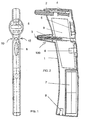
- Figure 1 shows, as stated above, one practical embodiment of an apparatus applying the principle according to the invention
- Figure 2 shows a cross section of it.
- the apparatus is formed of a case component 1 made of a suitable material, inside of which all the components that are essential for measurement are fitted.
- the case or body component 1 is essentially elongated and includes at its upper end a forehead support 2, which is intended to adjust the distance from which the probe 3 impacts the eye being measured.
- the forehead support 2 is specifically adjustable, one comfortable way of arranging adjustability being to use an adjustment wheel 4, which can be easily rotated with a finger.
- the apparatus includes a display and control component 5, which is particularly a liquid-crystal panel, in which the measurement result is displayed, and the related control buttons, etc, which are required at various times.
- Reference number 6 marks the operating switch, which, when pressed, releases the probe 3 towards the eye.
- Operating power for the apparatus comes from dry cells or batteries 7, while the apparatus can additionally have a socket 8, to which an external recharging device or power supply can be connected.
- the electronics of the apparatus according to the invention are assembled on a circuit board 9, which is shown schematically.
- Figure 1 clearly shows one property of the apparatus according to the invention that makes it more comfortable and accurate to use.
- This is the narrowed part, incorporated in the apparatus next to the probe 3.
- These narrowings are marked with the reference number 10. They are intended to allow patients performing self measurement to be able to see the coloured part of the eye through a mirror, on either side of the narrowing, so that it is easy for them to use this to align the measuring apparatus accurately, thus ensuring that the probe will strike the desired point on the surface of the eyeball.
- the narrowings 10 are located next to the probe 3.
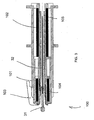
- Figure 3 shows the totality, marked with the reference number 100, relating to the launch of the probe of the apparatus according to the invention, the recording of the measurement, and other similar operations.
- the totality 100 includes two coils 101 and 102, the frontmost of which is intended to provide the probe 3 with the necessary velocity.
- the rearmost coil 102 is related to various measurement and settings functions.
- An inner tube 105 is held in place by an inner sleeve 104, which lies around the probe and is secured by means of a separate plug 103 particularly equipped with a screw attachment.
- the inner sleeve and the inner tube can be changed.
- the probe 3 can be changed while over time the inner sleeve and inner tube may also collect enough extraneous material for this to interfere with measurement in an apparatus with such small tolerances. As cleaning the sleeve and tube is difficult, it will then be easier to change them.
- the inner sleeve and the inner tube can be manufactured as a single integrated component.
- the probe can be formed of a non-magnetic point part 31 and a shaft part 32 of steel or other similar material.
- the point part 31 is preferably manufactured from a plastic material, for reasons of both manufacturing technique and manufacturing cost.
- Another characteristic of the probe is that a shoulder is formed where the point joins the shaft and is made to rest on the edges of the opening of the inner sleeve 104, through which the shaft part 32 runs. This positions the probe very precisely for the start of the measurement event. For reasons of hygiene, the point part of the probe is generally clearly outside the apparatus in the starting position.
- the non-magnetic point part of the probe is in such a ratio to the magnetic shaft part that the shaft extends for a certain distance inside the coil 101, preferably, for example, almost halfway into the coil, counting from its front, as shown in Figure 3 .
- the voltage fed to the coil induces a pushing force in the probe, causing it to move towards the eye.
- the probe had the problem that, under certain conditions, the eyelashes tended to catch on the front of the probe.
- the point part of the probe has now been given a very round shape, thus preventing catching.
- the simplified operation of the apparatus is as follows. Power is supplied to the front coil 101, causing the probe to begin moving and to impact the eye. The probe 3 rebounds and the movements, which take place in a manner depending on the intraocular pressure, are recorded with the aid of the rear coil 102, taken to a suitable data-processing unit to be processed particularly by a microprocessor, and the result is displayed by the display device 5. The power is connected to the coil 101 for the entire duration of the measurement, so that the power is cut off only when it is intended to pull the probe back inside.
- the stability of the measurement is adjusted in many ways, for example, by triggering the movement of the probe always using a constant voltage, which does not alter when the voltage of the dry cells drops.
- the constant voltage can be adjustable, making it possible to adjust the launch speed of the probe.
- the starting position of the probe 3 is also made constant in a suitable manner, for example, by having the shaft of the probe rest on its starting position in the inner sleeve 103. One way of ensuring the starting position is described above. Other ways can also be used.
- the apparatus can include a detection function, which, for instance, which monitors the probe's position and pulls a probe, which is trying to detach itself, back into place only when necessary.
- the voltage fed to the coil 101 to perform the actual measurement causes the probe to start moving.
- the rear coil 102 detects the speed of the probe continuously, the general principle being that the probe accelerates rapidly at the start, then, as the journey continues, a change in the voltage/current supplied to the coil reduces the acceleration to a constant, relatively low level, intended to maintain even motion.
- the input voltage/current of the coil 101 is on for the whole time that the probe proceeds towards the eye and impacts it, but can also be cut off at after the moment of impact.
- the rear coil 102 is activated and pulls the probe back to the starting position. This ensures that the probe does not detach due to the movements of the meter or for other reasons, but can be cleanly removed from its place and thrown into the garbage.
- the retraction of the probe can also be activated on the basis of time. This is because, if the probe has not struck the measurement object within a predetermined time, it can be assumed that the measurement has failed, in which case the retraction is activated.
- the core of the apparatus according to the invention is a microprocessor. It is easy to use this to also perform other control operations than those referred to above.
- the microprocessor can have the task of monitoring the measurement results and making error messages according to how a measurement result differs from the values to which the system should tend, according to data recorded for the use of the microprocessor. Monitoring and calculation functions of this kind are usual in microprocessor-based devices.
- the method can also be applied when the eyelid is closed.
- the low velocity and small mass of the probe eliminate the need to anaesthetize the eye under any measurement conditions. If necessary, the meter can be calibrated with different standards, by comparing the results with those obtained by other methods, or by using experimental methods.
- the apparatus according to the invention has several properties, by means of which ease of use, accuracy, and reliability can be improved and maintained. Many variations are possible while remaining within the scope of the inventive idea and the accompanying Claims.
- the front coil 101 giving the probe 3 launching power
- the rear coil 102 without this altering the characteristics of the apparatus.
- the physical properties of the coils are always selected as required.
- a microprocessor-based apparatus can perform many functions, which have previously been impossible.
- the measured variables could be the impact time of the probe, the time the probe is stationary, and the rebound time, while it is also possible to observe velocities and decelerations, and make various averages and ratios, etc. of them.
- One correction method is such in which the intraocular pressure is corrected upwards, in proportion to the inelasticity of the impact.
Landscapes
- Life Sciences & Earth Sciences (AREA)
- Health & Medical Sciences (AREA)
- Medical Informatics (AREA)
- Animal Behavior & Ethology (AREA)
- Ophthalmology & Optometry (AREA)
- Engineering & Computer Science (AREA)
- Biomedical Technology (AREA)
- Heart & Thoracic Surgery (AREA)
- Physics & Mathematics (AREA)
- Molecular Biology (AREA)
- Surgery (AREA)
- Biophysics (AREA)
- General Health & Medical Sciences (AREA)
- Public Health (AREA)
- Veterinary Medicine (AREA)
- Eye Examination Apparatus (AREA)
- Measuring Fluid Pressure (AREA)
- Measuring Pulse, Heart Rate, Blood Pressure Or Blood Flow (AREA)
- Ultra Sonic Daignosis Equipment (AREA)
Claims (10)
- Verfahren zur Messung des Augeninnendrucks mit einer Vorrichtung bestehend aus einer Sonde (3), die in einem Gehäuse (1) abgestützt und angeordnet ist, Mitteln (101, 102) zum Versetzen der Sonde (3) in eine spezifische Geschwindigkeit, Mitteln (102) zur Messung und Aufzeichnung der Geschwindigkeit, Mitteln zur Verarbeitung der Daten und Mitteln (5) zur Anzeige und Kontrolle von Funktionen, das Verfahren bestehend aus
Beaufschlagung der Mittel (101, 102) mit einer Spannung /einem Stromimpuls, um die Sonde in eine spezifische Geschwindigkeit zu versetzen, um die Sonde dadurch zu beschleunigen,
kontinuierlicher Ermittlung der Geschwindigkeit der Sonde mit Hilfe der Mittel (102) zur Messung und Aufzeichnung der Geschwindigkeit;
auf Basis der von den Mitteln (102) erhaltenen Daten zur Messung und Aufzeichnung der Geschwindigkeit oder wahlweise, nach einer konstanten Zeit, Zurücknahme des Betrags der/des den Mitteln (101 oder 102) zugeführten Spannung/Stromimpulses, um die Sonde (3) in eine spezifische Geschwindigkeit zu versetzen, um die Beschleunigung der Sonde (3) zu reduzieren und auf einem konstanten Nivea zu stabilisieren;
Aufrechterhalten der Spannung / des Stromimpulses zumindest bis zum Zeitpunkt des Aufschlags der Sonde auf dem Auge;
Messung des Aufschlags der Sonde mit Hilfe der Mittel (102) zur Messung und Aufzeichnung der Geschwindigkeit, um Messdaten zu berechnen und zu erhalten. - Verfahren nach Patentanspruch 1, dadurch gekennzeichnet, dass die Sonde (3) einen hinteren Teil (32) aus magnetischem Material und einen vorderen Teil (31) aufweist, der am hinteren Teil (32) angebracht ist und eine Schulter bildet, der aus einem nicht magnetischen Material besteht und eine rund geformte Spitze hat, wobei der Übergang zwischen dem vorderen Teil (31) und dem hinteren Teil (32) zu Beginn der Messung innerhalb der Mittel (101, 102) positioniert ist, um die Sonde in eine spezifischen Geschwindigkeit in einem Abstand von der Vorderseite der Mittel zur Messung und Aufzeichnung der Geschwindigkeit zu versetzen.
- Verfahren nach Patentanspruch 1, dadurch gekennzeichnet, dass die Sonde (3), abgesehen vom Messvorgang, mit Hilfe der Mittel (102) zur Messung und Aufzeichnung der Geschwindigkeit in Position gehalten wird, wenn die Vorrichtung eingeschaltet wird.
- Verfahren nach Patentanspruch 1, dadurch gekennzeichnet, dass das Gehäuse (1) eine Einengung im Wesentlich benachbart zur Sonde (3) hat, damit Teile des zu vermessenden Auges gesehen werden können, um Genauigkeit sicherzustellen.
- Verfahren nach Patentanspruch 1, dadurch gekennzeichnet, dass in der Vorrichtung ein austauschbares Innenrohr (105), dessen Inneres den hinteren Teil der Sonde (3) aufnimmt, und eine Innenhülse (104) angeordnet sind, um das Innenrohr in Position zu halten.
- Verfahren nach Patentanspruch 2, dadurch gekennzeichnet, dass die Schulter zwischen dem vorderen Teil (31) und dem hinteren Teil (32) der Sonde (3) zu Beginn der Messung an einer Öffnung in der Innenhülse (104) anliegt, die eine Kante des hinteren Teils (32) der Sonde (3) aufnimmt.
- Verfahren nach Patentanspruch 1, dadurch gekennzeichnet, dass es des Weiteren die Korrektur der Messdaten auf Basis eines Algorithmus umfasst.
- Verfahren nach Patentanspruch 1, dadurch gekennzeichnet, dass es des Weiteren die Korrektur der Messdaten davon abhängig umfasst, wie viel kinetische Energie beim Aufprall und Rückprall der Sonde verloren geht.
- Verfahren nach Patentanspruch 1, dadurch gekennzeichnet, dass es sich bei den Mitteln (101, 102) zum Versetzen der Sonde in eine spezifische Geschwindigkeit um eine Spule handelt.
- Verfahren nach Patentanspruch 1, dadurch gekennzeichnet, dass es des Weiteren das Zurückziehen der Sonde in eine Position innerhalb der Vorrichtung umfasst, indem die den Mitteln zugeführte Spannung zur Messung und Aufzeichnung der Geschwindigkeit benutzt wird.
Applications Claiming Priority (3)
| Application Number | Priority Date | Filing Date | Title |
|---|---|---|---|
| FI20021172 | 2002-06-17 | ||
| FI20021172A FI113450B (fi) | 2002-06-17 | 2002-06-17 | Laite silmänpaineen mittaamiseksi |
| PCT/FI2003/000490 WO2003105681A1 (en) | 2002-06-17 | 2003-06-17 | A method for measuring intraocular pressure |
Publications (2)
| Publication Number | Publication Date |
|---|---|
| EP1545294A1 EP1545294A1 (de) | 2005-06-29 |
| EP1545294B1 true EP1545294B1 (de) | 2008-02-27 |
Family
ID=8564170
Family Applications (2)
| Application Number | Title | Priority Date | Filing Date |
|---|---|---|---|
| EP03738144A Expired - Lifetime EP1513442B1 (de) | 2002-06-17 | 2003-06-17 | Gerät zur messung des augeninnendrucks |
| EP03732603A Expired - Lifetime EP1545294B1 (de) | 2002-06-17 | 2003-06-17 | Verfahren zur messung des augeninnendrucks |
Family Applications Before (1)
| Application Number | Title | Priority Date | Filing Date |
|---|---|---|---|
| EP03738144A Expired - Lifetime EP1513442B1 (de) | 2002-06-17 | 2003-06-17 | Gerät zur messung des augeninnendrucks |
Country Status (9)
| Country | Link |
|---|---|
| EP (2) | EP1513442B1 (de) |
| JP (2) | JP4478014B2 (de) |
| AT (2) | ATE387138T1 (de) |
| AU (2) | AU2003239630A1 (de) |
| DE (2) | DE60318705T2 (de) |
| DK (2) | DK1513442T3 (de) |
| ES (2) | ES2300592T3 (de) |
| FI (1) | FI113450B (de) |
| WO (2) | WO2003105680A1 (de) |
Cited By (1)
| Publication number | Priority date | Publication date | Assignee | Title |
|---|---|---|---|---|
| CN110584595A (zh) * | 2018-06-13 | 2019-12-20 | 李克特有限公司 | 回弹式眼压测量方法和装置 |
Families Citing this family (10)
| Publication number | Priority date | Publication date | Assignee | Title |
|---|---|---|---|---|
| DE102004019955A1 (de) * | 2004-01-12 | 2005-11-17 | Emil Hohl | Verfahren und Vorrichtung zum Messen des Innendruckes eines elastischen Prüfkörpers, insbesondere zum Messen des Augeninnendruckes |
| DE102004001675B4 (de) * | 2004-01-12 | 2009-01-29 | Emil Hohl | Verfahren und Vorrichtung zum Messen des Innendruckes eines elastischen Prüfkörpers, insbesondere zum Messen des Augeninnendruckes |
| FI119096B (fi) | 2004-12-21 | 2008-07-31 | Tiolat Oy | Sovitelma silmänpainemittarissa |
| IL166962A (en) * | 2005-02-17 | 2012-06-28 | Ait Advanced Medical Technologies Ltd | Device and method for intra-ocular pressure measurment |
| RU2308217C1 (ru) | 2006-05-12 | 2007-10-20 | Геннадий Константинович Пилецкий | Устройство для измерения внутриглазного давления через веко |
| CN101190122B (zh) | 2006-11-30 | 2012-01-11 | 蒂奥拉特公司 | 测量眼内压的方法 |
| CN101773381A (zh) * | 2010-03-05 | 2010-07-14 | 天津索维电子技术有限公司 | 一种测量眼内压的设备及用该设备测量眼内压的方法 |
| JP6471378B2 (ja) * | 2014-08-28 | 2019-02-20 | 新電元メカトロニクス株式会社 | 空気噴出装置 |
| FI127018B (en) * | 2015-12-18 | 2017-09-29 | Icare Finland Oy | APPARATUS FOR MEASURING ILLUMINARY PRESSURE |
| FI129466B (en) * | 2018-06-08 | 2022-02-28 | Icare Finland Oy | METHOD AND SYSTEM FOR DETERMINING THE TOUCH SENSITIVITY LIMIT |
Family Cites Families (6)
| Publication number | Priority date | Publication date | Assignee | Title |
|---|---|---|---|---|
| RU2007951C1 (ru) * | 1990-06-29 | 1994-02-28 | Федоров Святослав Николаевич | Способ измерения и индикации внутриглазного давления и тонометр-индикатор для его осуществления |
| FI100765B (fi) * | 1994-08-30 | 1998-02-27 | Antti Ilmari Kontiola | Menetelmä ja laite silmän sisäisen paineen mittaamiseksi |
| US5865742A (en) * | 1995-03-06 | 1999-02-02 | Massie Research Laboratories, Inc. | Non-contact tonometer |
| RU2123798C1 (ru) * | 1998-02-05 | 1998-12-27 | Пилецкий Геннадий Константинович | Способ измерения внутриглазного давления через веко и устройство для осуществления способа |
| US6093147A (en) * | 1999-02-22 | 2000-07-25 | Kontiola; Antti | Apparatus for measuring intraocular pressure |
| US6361495B1 (en) * | 2000-02-07 | 2002-03-26 | Leica Microsystems Inc. | Hand-held non-contact tonometer |
-
2002
- 2002-06-17 FI FI20021172A patent/FI113450B/fi not_active IP Right Cessation
-
2003
- 2003-06-17 DK DK03738144T patent/DK1513442T3/da active
- 2003-06-17 WO PCT/FI2003/000489 patent/WO2003105680A1/en not_active Ceased
- 2003-06-17 AT AT03732603T patent/ATE387138T1/de not_active IP Right Cessation
- 2003-06-17 AT AT03738144T patent/ATE383809T1/de not_active IP Right Cessation
- 2003-06-17 ES ES03738144T patent/ES2300592T3/es not_active Expired - Lifetime
- 2003-06-17 JP JP2004512596A patent/JP4478014B2/ja not_active Expired - Lifetime
- 2003-06-17 EP EP03738144A patent/EP1513442B1/de not_active Expired - Lifetime
- 2003-06-17 ES ES03732603T patent/ES2300583T3/es not_active Expired - Lifetime
- 2003-06-17 DE DE60318705T patent/DE60318705T2/de not_active Expired - Lifetime
- 2003-06-17 EP EP03732603A patent/EP1545294B1/de not_active Expired - Lifetime
- 2003-06-17 DK DK03732603T patent/DK1545294T3/da active
- 2003-06-17 WO PCT/FI2003/000490 patent/WO2003105681A1/en not_active Ceased
- 2003-06-17 JP JP2004512597A patent/JP4478015B2/ja not_active Expired - Lifetime
- 2003-06-17 DE DE60319392T patent/DE60319392T2/de not_active Expired - Lifetime
- 2003-06-17 AU AU2003239630A patent/AU2003239630A1/en not_active Abandoned
- 2003-06-17 AU AU2003244665A patent/AU2003244665A1/en not_active Abandoned
Cited By (4)
| Publication number | Priority date | Publication date | Assignee | Title |
|---|---|---|---|---|
| CN110584595A (zh) * | 2018-06-13 | 2019-12-20 | 李克特有限公司 | 回弹式眼压测量方法和装置 |
| EP3581089B1 (de) | 2018-06-13 | 2020-12-23 | Reichert, Inc. | Verfahren und vorrichtung für rebound-tonometrie |
| US11026577B2 (en) | 2018-06-13 | 2021-06-08 | Reichert, Inc. | Rebound tonometry method and apparatus |
| CN110584595B (zh) * | 2018-06-13 | 2022-12-02 | 李克特有限公司 | 回弹式眼压测量方法和装置 |
Also Published As
| Publication number | Publication date |
|---|---|
| DE60319392T2 (de) | 2009-04-02 |
| JP2005529670A (ja) | 2005-10-06 |
| JP4478015B2 (ja) | 2010-06-09 |
| WO2003105681A1 (en) | 2003-12-24 |
| AU2003244665A1 (en) | 2003-12-31 |
| JP2005529671A (ja) | 2005-10-06 |
| ATE387138T1 (de) | 2008-03-15 |
| EP1545294A1 (de) | 2005-06-29 |
| DE60318705T2 (de) | 2009-01-08 |
| FI113450B (fi) | 2004-04-30 |
| ATE383809T1 (de) | 2008-02-15 |
| FI20021172A7 (fi) | 2003-12-18 |
| ES2300583T3 (es) | 2008-06-16 |
| DK1545294T3 (da) | 2008-06-30 |
| EP1513442B1 (de) | 2008-01-16 |
| DE60318705D1 (de) | 2008-03-06 |
| ES2300592T3 (es) | 2008-06-16 |
| EP1513442A1 (de) | 2005-03-16 |
| JP4478014B2 (ja) | 2010-06-09 |
| DK1513442T3 (da) | 2008-05-26 |
| FI20021172A0 (fi) | 2002-06-17 |
| DE60319392D1 (de) | 2008-04-10 |
| AU2003239630A1 (en) | 2003-12-31 |
| WO2003105680A1 (en) | 2003-12-24 |
Similar Documents
| Publication | Publication Date | Title |
|---|---|---|
| EP1927315B1 (de) | Verfahren zur Messung des Intraokulardrucks | |
| US12171497B2 (en) | Apparatus for measuring intraocular pressure | |
| US6093147A (en) | Apparatus for measuring intraocular pressure | |
| EP1545294B1 (de) | Verfahren zur messung des augeninnendrucks | |
| EP3681374B1 (de) | Rebound-tonometer mit neigungskorrektur | |
| US8323196B2 (en) | Device for measuring intraocular pressure through an eyelid | |
| US20050137473A1 (en) | Apparatus for measuring intraocular pressure | |
| US20050137474A1 (en) | Method for measuring intraocular pressure | |
| JP3638953B2 (ja) | 眼圧測定方法および装置 | |
| EP4356817A1 (de) | Ophthalmologisches messsystem mit einer ophthalmologischen messvorrichtung und einer funktions- und/oder kalibriervorrichtung | |
| JP7519467B2 (ja) | 眼科機器用フレキシブルヘッドレスト | |
| US20260053359A1 (en) | Device and method of measuring properties of target |
Legal Events
| Date | Code | Title | Description |
|---|---|---|---|
| PUAI | Public reference made under article 153(3) epc to a published international application that has entered the european phase |
Free format text: ORIGINAL CODE: 0009012 |
|
| 17P | Request for examination filed |
Effective date: 20041202 |
|
| AK | Designated contracting states |
Kind code of ref document: A1 Designated state(s): AT BE BG CH CY CZ DE DK EE ES FI FR GB GR HU IE IT LI LU MC NL PT RO SE SI SK TR |
|
| AX | Request for extension of the european patent |
Extension state: AL LT LV MK |
|
| DAX | Request for extension of the european patent (deleted) | ||
| 17Q | First examination report despatched |
Effective date: 20061220 |
|
| 17Q | First examination report despatched |
Effective date: 20061220 |
|
| GRAP | Despatch of communication of intention to grant a patent |
Free format text: ORIGINAL CODE: EPIDOSNIGR1 |
|
| GRAS | Grant fee paid |
Free format text: ORIGINAL CODE: EPIDOSNIGR3 |
|
| GRAA | (expected) grant |
Free format text: ORIGINAL CODE: 0009210 |
|
| AK | Designated contracting states |
Kind code of ref document: B1 Designated state(s): AT BE BG CH CY CZ DE DK EE ES FI FR GB GR HU IE IT LI LU MC NL PT RO SE SI SK TR |
|
| REG | Reference to a national code |
Ref country code: GB Ref legal event code: FG4D |
|
| REG | Reference to a national code |
Ref country code: CH Ref legal event code: EP |
|
| REG | Reference to a national code |
Ref country code: IE Ref legal event code: FG4D |
|
| REF | Corresponds to: |
Ref document number: 60319392 Country of ref document: DE Date of ref document: 20080410 Kind code of ref document: P |
|
| REG | Reference to a national code |
Ref country code: ES Ref legal event code: FG2A Ref document number: 2300583 Country of ref document: ES Kind code of ref document: T3 |
|
| REG | Reference to a national code |
Ref country code: SE Ref legal event code: TRGR |
|
| REG | Reference to a national code |
Ref country code: CH Ref legal event code: NV Representative=s name: FREI PATENTANWALTSBUERO AG |
|
| REG | Reference to a national code |
Ref country code: DK Ref legal event code: T3 |
|
| PG25 | Lapsed in a contracting state [announced via postgrant information from national office to epo] |
Ref country code: FI Free format text: LAPSE BECAUSE OF FAILURE TO SUBMIT A TRANSLATION OF THE DESCRIPTION OR TO PAY THE FEE WITHIN THE PRESCRIBED TIME-LIMIT Effective date: 20080227 |
|
| PG25 | Lapsed in a contracting state [announced via postgrant information from national office to epo] |
Ref country code: AT Free format text: LAPSE BECAUSE OF FAILURE TO SUBMIT A TRANSLATION OF THE DESCRIPTION OR TO PAY THE FEE WITHIN THE PRESCRIBED TIME-LIMIT Effective date: 20080227 |
|
| PG25 | Lapsed in a contracting state [announced via postgrant information from national office to epo] |
Ref country code: BE Free format text: LAPSE BECAUSE OF FAILURE TO SUBMIT A TRANSLATION OF THE DESCRIPTION OR TO PAY THE FEE WITHIN THE PRESCRIBED TIME-LIMIT Effective date: 20080227 Ref country code: SI Free format text: LAPSE BECAUSE OF FAILURE TO SUBMIT A TRANSLATION OF THE DESCRIPTION OR TO PAY THE FEE WITHIN THE PRESCRIBED TIME-LIMIT Effective date: 20080227 |
|
| PGFP | Annual fee paid to national office [announced via postgrant information from national office to epo] |
Ref country code: TR Payment date: 20080613 Year of fee payment: 6 |
|
| ET | Fr: translation filed | ||
| PG25 | Lapsed in a contracting state [announced via postgrant information from national office to epo] |
Ref country code: PT Free format text: LAPSE BECAUSE OF FAILURE TO SUBMIT A TRANSLATION OF THE DESCRIPTION OR TO PAY THE FEE WITHIN THE PRESCRIBED TIME-LIMIT Effective date: 20080721 Ref country code: CZ Free format text: LAPSE BECAUSE OF FAILURE TO SUBMIT A TRANSLATION OF THE DESCRIPTION OR TO PAY THE FEE WITHIN THE PRESCRIBED TIME-LIMIT Effective date: 20080227 Ref country code: SK Free format text: LAPSE BECAUSE OF FAILURE TO SUBMIT A TRANSLATION OF THE DESCRIPTION OR TO PAY THE FEE WITHIN THE PRESCRIBED TIME-LIMIT Effective date: 20080227 |
|
| PGFP | Annual fee paid to national office [announced via postgrant information from national office to epo] |
Ref country code: DK Payment date: 20080630 Year of fee payment: 6 Ref country code: IE Payment date: 20080624 Year of fee payment: 6 Ref country code: NL Payment date: 20080624 Year of fee payment: 6 |
|
| PG25 | Lapsed in a contracting state [announced via postgrant information from national office to epo] |
Ref country code: RO Free format text: LAPSE BECAUSE OF FAILURE TO SUBMIT A TRANSLATION OF THE DESCRIPTION OR TO PAY THE FEE WITHIN THE PRESCRIBED TIME-LIMIT Effective date: 20080227 |
|
| PLBE | No opposition filed within time limit |
Free format text: ORIGINAL CODE: 0009261 |
|
| STAA | Information on the status of an ep patent application or granted ep patent |
Free format text: STATUS: NO OPPOSITION FILED WITHIN TIME LIMIT |
|
| PG25 | Lapsed in a contracting state [announced via postgrant information from national office to epo] |
Ref country code: MC Free format text: LAPSE BECAUSE OF NON-PAYMENT OF DUE FEES Effective date: 20080630 |
|
| 26N | No opposition filed |
Effective date: 20081128 |
|
| PG25 | Lapsed in a contracting state [announced via postgrant information from national office to epo] |
Ref country code: EE Free format text: LAPSE BECAUSE OF FAILURE TO SUBMIT A TRANSLATION OF THE DESCRIPTION OR TO PAY THE FEE WITHIN THE PRESCRIBED TIME-LIMIT Effective date: 20080227 Ref country code: BG Free format text: LAPSE BECAUSE OF FAILURE TO SUBMIT A TRANSLATION OF THE DESCRIPTION OR TO PAY THE FEE WITHIN THE PRESCRIBED TIME-LIMIT Effective date: 20080527 |
|
| PG25 | Lapsed in a contracting state [announced via postgrant information from national office to epo] |
Ref country code: CY Free format text: LAPSE BECAUSE OF FAILURE TO SUBMIT A TRANSLATION OF THE DESCRIPTION OR TO PAY THE FEE WITHIN THE PRESCRIBED TIME-LIMIT Effective date: 20080227 |
|
| REG | Reference to a national code |
Ref country code: DK Ref legal event code: EBP |
|
| NLV4 | Nl: lapsed or anulled due to non-payment of the annual fee |
Effective date: 20100101 |
|
| PG25 | Lapsed in a contracting state [announced via postgrant information from national office to epo] |
Ref country code: IE Free format text: LAPSE BECAUSE OF NON-PAYMENT OF DUE FEES Effective date: 20090617 |
|
| PG25 | Lapsed in a contracting state [announced via postgrant information from national office to epo] |
Ref country code: LU Free format text: LAPSE BECAUSE OF NON-PAYMENT OF DUE FEES Effective date: 20080617 Ref country code: DK Free format text: LAPSE BECAUSE OF NON-PAYMENT OF DUE FEES Effective date: 20090630 Ref country code: NL Free format text: LAPSE BECAUSE OF NON-PAYMENT OF DUE FEES Effective date: 20100101 Ref country code: HU Free format text: LAPSE BECAUSE OF FAILURE TO SUBMIT A TRANSLATION OF THE DESCRIPTION OR TO PAY THE FEE WITHIN THE PRESCRIBED TIME-LIMIT Effective date: 20080828 |
|
| PG25 | Lapsed in a contracting state [announced via postgrant information from national office to epo] |
Ref country code: GR Free format text: LAPSE BECAUSE OF FAILURE TO SUBMIT A TRANSLATION OF THE DESCRIPTION OR TO PAY THE FEE WITHIN THE PRESCRIBED TIME-LIMIT Effective date: 20080528 |
|
| PG25 | Lapsed in a contracting state [announced via postgrant information from national office to epo] |
Ref country code: TR Free format text: LAPSE BECAUSE OF NON-PAYMENT OF DUE FEES Effective date: 20090617 |
|
| REG | Reference to a national code |
Ref country code: FR Ref legal event code: PLFP Year of fee payment: 14 |
|
| REG | Reference to a national code |
Ref country code: FR Ref legal event code: PLFP Year of fee payment: 15 |
|
| REG | Reference to a national code |
Ref country code: FR Ref legal event code: PLFP Year of fee payment: 16 |
|
| REG | Reference to a national code |
Ref country code: CH Ref legal event code: PCAR Free format text: NEW ADDRESS: POSTFACH, 8032 ZUERICH (CH) |
|
| REG | Reference to a national code |
Ref country code: DE Ref legal event code: R081 Ref document number: 60319392 Country of ref document: DE Owner name: ICARE FINLAND OY, FI Free format text: FORMER OWNER: TIOLAT OY, HELSINKI, FI |
|
| REG | Reference to a national code |
Ref country code: ES Ref legal event code: PC2A Owner name: ICARE FINLAND OY Effective date: 20220712 |
|
| PGFP | Annual fee paid to national office [announced via postgrant information from national office to epo] |
Ref country code: SE Payment date: 20220623 Year of fee payment: 20 Ref country code: IT Payment date: 20220620 Year of fee payment: 20 Ref country code: GB Payment date: 20220617 Year of fee payment: 20 Ref country code: DE Payment date: 20220621 Year of fee payment: 20 |
|
| PGFP | Annual fee paid to national office [announced via postgrant information from national office to epo] |
Ref country code: FR Payment date: 20220614 Year of fee payment: 20 |
|
| PGFP | Annual fee paid to national office [announced via postgrant information from national office to epo] |
Ref country code: ES Payment date: 20220831 Year of fee payment: 20 |
|
| PGFP | Annual fee paid to national office [announced via postgrant information from national office to epo] |
Ref country code: CH Payment date: 20220622 Year of fee payment: 20 |
|
| REG | Reference to a national code |
Ref country code: DE Ref legal event code: R071 Ref document number: 60319392 Country of ref document: DE |
|
| REG | Reference to a national code |
Ref country code: ES Ref legal event code: FD2A Effective date: 20230626 |
|
| REG | Reference to a national code |
Ref country code: CH Ref legal event code: PL |
|
| P01 | Opt-out of the competence of the unified patent court (upc) registered |
Effective date: 20230529 |
|
| REG | Reference to a national code |
Ref country code: GB Ref legal event code: PE20 Expiry date: 20230616 |
|
| PG25 | Lapsed in a contracting state [announced via postgrant information from national office to epo] |
Ref country code: ES Free format text: LAPSE BECAUSE OF EXPIRATION OF PROTECTION Effective date: 20230618 |
|
| REG | Reference to a national code |
Ref country code: SE Ref legal event code: EUG |
|
| PG25 | Lapsed in a contracting state [announced via postgrant information from national office to epo] |
Ref country code: GB Free format text: LAPSE BECAUSE OF EXPIRATION OF PROTECTION Effective date: 20230616 |