EP1545250B1 - Energieabsorbierendes kleidungsstück - Google Patents
Energieabsorbierendes kleidungsstück Download PDFInfo
- Publication number
- EP1545250B1 EP1545250B1 EP03741694A EP03741694A EP1545250B1 EP 1545250 B1 EP1545250 B1 EP 1545250B1 EP 03741694 A EP03741694 A EP 03741694A EP 03741694 A EP03741694 A EP 03741694A EP 1545250 B1 EP1545250 B1 EP 1545250B1
- Authority
- EP
- European Patent Office
- Prior art keywords
- garment
- panel
- panels
- energy absorbing
- adjacent
- Prior art date
- Legal status (The legal status is an assumption and is not a legal conclusion. Google has not performed a legal analysis and makes no representation as to the accuracy of the status listed.)
- Expired - Lifetime
Links
- 239000000463 material Substances 0.000 claims description 11
- 239000004033 plastic Substances 0.000 claims description 11
- 229920003023 plastic Polymers 0.000 claims description 11
- 239000004744 fabric Substances 0.000 claims description 9
- 238000005192 partition Methods 0.000 claims description 3
- 239000006260 foam Substances 0.000 description 8
- 238000009863 impact test Methods 0.000 description 6
- 239000002184 metal Substances 0.000 description 5
- 210000001562 sternum Anatomy 0.000 description 5
- 239000004677 Nylon Substances 0.000 description 4
- 229920001778 nylon Polymers 0.000 description 4
- 210000003127 knee Anatomy 0.000 description 3
- 208000027418 Wounds and injury Diseases 0.000 description 2
- 230000000295 complement effect Effects 0.000 description 2
- 230000006378 damage Effects 0.000 description 2
- 230000000694 effects Effects 0.000 description 2
- 208000014674 injury Diseases 0.000 description 2
- 230000001681 protective effect Effects 0.000 description 2
- 230000001133 acceleration Effects 0.000 description 1
- 230000004075 alteration Effects 0.000 description 1
- 230000015572 biosynthetic process Effects 0.000 description 1
- 210000001217 buttock Anatomy 0.000 description 1
- 210000000038 chest Anatomy 0.000 description 1
- 230000003247 decreasing effect Effects 0.000 description 1
- 210000002310 elbow joint Anatomy 0.000 description 1
- 239000011810 insulating material Substances 0.000 description 1
- 210000000629 knee joint Anatomy 0.000 description 1
- 238000005259 measurement Methods 0.000 description 1
- 238000012986 modification Methods 0.000 description 1
- 230000004048 modification Effects 0.000 description 1
- 230000001012 protector Effects 0.000 description 1
- 238000009958 sewing Methods 0.000 description 1
- 210000000323 shoulder joint Anatomy 0.000 description 1
Images



Classifications
-
- A—HUMAN NECESSITIES
- A41—WEARING APPAREL
- A41D—OUTERWEAR; PROTECTIVE GARMENTS; ACCESSORIES
- A41D13/00—Professional, industrial or sporting protective garments, e.g. surgeons' gowns or garments protecting against blows or punches
- A41D13/015—Professional, industrial or sporting protective garments, e.g. surgeons' gowns or garments protecting against blows or punches with shock-absorbing means
Definitions
- the invention relates to an energy absorbing garment and in particular to an energy absorbing garment adapted to absorb energy from an impact or fall.
- Conventional equestrian protection clothing uses 15 to 20mm thick foam plastics blocks arranged in a manner similar to a buoyancy aid. These blocks have the ability to absorb impact energy, but limited ability to spread it out over the body.
- foam plastics is an insulating material and wearers of foam plastics equestrian protection consider that garments using the blocks are hot and uncomfortable as well as bulky and inflexible. Whilst foam plastics blocks absorb impact energy from a fall or other low grade impacts the foam plastics blocks are less effective in directed impacts such as a kick from a horse.
- US patent 5,794,261 describes a joint protective guard for use in sports such as softball and baseball.
- the guard includes a number of curved pieces each having an upper surface level and a lower surface level. The lower level of each piece is attached to the upper level of the next piece at each end so that two pieces are pivotable relative to each other. This allows the guard to be flexed to fit around a wearer's shoulder, elbow or knee joint without leaving any of the joint exposed.
- this system does not spread the energy of an impact and is limited in usefulness to moveable joints.
- a second existing system is described by US patent 4,241,457 and comprises a bullet proof vest.
- the vest of the invention includes two layers of segmented panels. Each layer of panels comprises a plurality of panels that are regularly shaped and in a compressed state sit flat, side by side.
- the lower layer of panels is offset from the upper layer with a major portion of corresponding segmented panels in each layer overlapping. Panels are adhered in the major portion of overlap.
- the lower layer of panels is also adhered to a backing material. In this way the layers of panels can be flexed in a convex direction from the backing material.
- a bullet or other object impacts on a panel in the upper layer of panels the panel moves to its compressed state and spreads the impact energy into the adjacent panels in the lower layer.
- the panels in the lower layer also move to the compressed state and further spread the impact energy to any adjacent panels in the upper layer and so on.
- the disadvantage of this system is that the panels all move to the rigid compressed state when impacted which reduces the flexibility of the vest
- US Patent No 4,004,493 discloses a bullet proof garment which has a first layer of nylon fabric that forms an inner portion of the garment, and further includes an outer layer of the garment nylon.
- the garment also includes a plurality of small metal plates each bent into a U-shape, and a plurality of small rings to permit sewing of the rings to the first layer of the nylon fabric.
- the rings are attached to the metal clips by a clipping action, and the outer layer of the garment nylon is glued to the metal. While the U-shaped metal plates may deform on impact, the degree to which the metal plates overlap and slide relative to each other is severely restricted by the need to secure the plates to both the inner layer and the outer layer.
- the invention comprises an energy absorbing and/or spreading garment having an inner layer, an outer layer, and a plurality of panels housed between the inner layer and the outer layer of the garment, characterised in that :
- each channel in the garment is arranged to house one column of arcuate panels.
- each panel includes two lower side portions and a higher middle portion.
- the panels are arranged so that one side portion of a first panel is adjacent to the middle portion of a second panel.
- One side portion of the second panel is adjacent the middle portion of a third panel etc.
- each panel is arranged in a sliding relationship with the adjacent panels.
- the panels are arranged in a symmetrical pattern with the axis of symmetry running between the centre of the front of the garment and the centre of the back of the garment.
- a centre panel with higher middle portion and lower side portions is situated between a first left side panel and a first right side panel. Both the first left side panel and the first right side panel have one side adjacent the middle portion of the centre panel.
- a second left side panel has one side adjacent the middle of the first left side panel.
- a second right side panel has one side adjacent the middle of the first right side panels etc.
- each panel is arranged in a sliding relationship with the adjacent panels.
- each panel extends between a first side and a second side and includes an upper and lower middle portion.
- the panels are arranged so that the lower middle portion of a first panel is adjacent a first side portion of a second panel.
- the second side portion of the first panel is adjacent to the upper middle portion of the second panel.
- the lower middle portion of the second where panels form columns in each channel.
- the garment may also be provided with overlap between the panels in each channel, i.e. there may be overlap between the panels in each channel.
- the panels are formed from resilient deformable material. Ideally the panels are formed from material that deforms upon impact but regains its shape after impact. Preferably in this embodiment the panels are formed from plastics. Ideally the panels are formed from PVC and/or laminates.
- the garment may further be provided with perforations to allow air to flow through the garment to a wearer. In other embodiments no perforations are provided.
- the inner and outer layers of the garment are formed of fabric.
- the fabric of the inner and outer layers includes one-way stretchability. Ideally this stretchability is arranged to run across the garment.
- Figure 1 is a cut away portion of a garment showing a series of panels between the inner and outer layers of the garment
- Figure 2 shows a series of panels connected together between the inner and outer layers of the garment
- Figure 3A shows an impact test on a portion of a garment of the invention from a first drop height
- Figure 3B shows an impact test on a portion of a garment of the invention from a second drop height
- Figure 3C shows an impact test on a portion of a garment of the invention from a third drop height
- Figure 3D shows an impact test on a portion of a garment of the invention from a fourth drop height
- Figure 4 is a graph showing the loading on the panels for each of the impact tests of Figures 3A to 3D
- Figure 5 shows the connections between a series of panels of one embodiment of the invention
- Figure 6 is a top view of the panels of Figure 5 showing the connections between the panels
- Figure 7 is an
- Figure 1 shows a cut out portion of a garment of the invention showing an outer layer of the garment 1, an inner layer 2, a plurality of panels 3 - 6, and channels between the outer and inner layers of the garment formed by strips 7.
- the panels have an arcuate cross-section 8 with two lower sides and a higher middle section.
- the cross-section extends through the panel from the front end to the back end providing a panel with regular cross-section and shape.
- the panels are arranged, in a sliding arrangement, in a symmetrical arrangement with the axis of symmetry running between the centre of the front of the garment and the centre of the back of the garment.
- the axis of symmetry runs between the breastbone and the spine.
- panel 6 has a different dimensions to the other panels.
- panel 6 is symmetrical and has greater height between the middle portion and the side portions than panels 5 - 3.
- panels 5 - 3 (the right side panels) have a flatter left side than right side.
- the left side panels are ideally mirror images of the right side panels.
- Panel 6 is designed to sit in front of the breastbone or spine.
- panel 6 is in front of the breastbone panels 5 - 3 run towards the right of a wearer of the garment. Further panels are provided that are arranged symmetrically to panels 5 - 3 on the other side of panel 6. The same configuration may be included at the back of the garment with a column of panels 6 sitting over the spine. This provides added protection to vulnerable parts of the body like the breastbone and spine. In the case of the spine for further protection a larger panel with smaller radius of curvature may be provided. This larger panel sits over panel 6 and at least a portion of the panels on either side of panel 6.
- the centre panel is situated between a first left side panel and a first right side panel. Both the first left side panel and the first right side panel have one side adjacent the middle portion of the centre panel.
- a second left side panel has one side adjacent the middle of the first left side panel.
- a second right side panel has one side adjacent the middle of the first right side panels etc.
- each panel is arranged in a sliding relationship with the adjacent panels.
- the panels are arranged in a sliding arrangement so that the first side of first panel 3 overlaps adjacent panel 4. The first side of panel 4 then overlaps adjacent panel 5, etc. This arrangement may be continued to form a complete loop around the garment. If the panels are not arranged to form a complete loop then the second side of one panel on one end (for example panel 3 in Figure 1 ) is not adjacent any other panel and the first side of the panel on the other end (for example panel 6 in Figure 1 ) is not adjacent any other panel.
- FIG 1 the sliding arrangement of the panels 3 - 6 is assisted by the formation of channels between the outer layer 1 of the garment and the inner layer 2 of the garment.
- Partition strips 7 that extend between the outer and inner layers of the garment form these channels.
- Each channel is arranged to house one panel as shown in Figure 1 or a column of panels.
- the strips 2 are shown at an angle between the outer and inner layers when formed the strips may run perpendicular to the outer and inner layers.
- the panels are slotted into the channels.
- the outer layer is then rotated in direction 9 with respect to the inner layer to produce the arrangement of the panels and channels as shown in Figure 1 .
- Figure 2 shows an alternative arrangement of the panels that allows the panels to move in a sliding relationship.
- Figure 2 is an end-on view of a cut-away part of the garment with outer layer 1 and inner layer 2 as before.
- Strip 7 forms part of a channel between the inner and outer layers of the garment.
- Panels 3, 4 and 5 are connected together in a row in a sliding manner by rivets 11, 12.
- Each rivet connects the middle section of one panel to one side of the adjacent panel.
- rivet 11 connects the middle portion of panel 3 to one side of panel 4.
- the sides of the panels adjacent the centre of other panels have a hole formed in the side to accommodate the rivet and the centre of each panel includes a slot arranged to accommodate the rivet and to allow the rivet to move up and down the slot.
- Each panel may have more than one hole and slot along its length as shown in Figure 6 .
- the garment is designed to withstand impact forces such as those that occur when a horse rider falls off a horse or onto an obstacle on the ground. Impacts from falling off a horse or being kicked by a horse will impact on the garment from the outside of the garment in the general direction shown by arrow 10 (of Figure 1 ). Impacts of sufficient force cause the panels of the garment to deform. This deformation of the panels spreads the energy of the impact. The panels also slide against each other further spreading the force of the impact. The garment reduces and spreads the impact force felt by the wearer thereby preventing an injury or reducing the severity of an injury.
- impact forces such as those that occur when a horse rider falls off a horse or onto an obstacle on the ground. Impacts from falling off a horse or being kicked by a horse will impact on the garment from the outside of the garment in the general direction shown by arrow 10 (of Figure 1 ). Impacts of sufficient force cause the panels of the garment to deform. This deformation of the panels spreads the energy of the impact. The panels also slide against each
- the panels used in garments suitable for equestrian protection are formed from resilient deformable material.
- the material of the panels must be sufficiently deformable to deform under large impact forces.
- the panels must also be resilient and regain their original shape after impact.
- Some plastics are suitable materials for panels.
- 3mm thick PVC is a suitable panel material. Any other material with suitable resiliency and deformation characteristics may be used for the panels. These panels may also be used in other protective clothing, for example as part of hard hats etc.
- Figures 3A to 3D show an impact test performed on a portion of a garment of the invention.
- the impact was provided by an 80mm diameter, 5kg drop impactor 45 on a sliding track.
- This impactor has a weight specification similar to that specified by The Beta Standard for Horse Riders' Body and Shoulder Protectors by the British Equestrian Trade Association Limited (BETA).
- BETA British Equestrian Trade Association Limited
- the impactor was attached to an accelerator and the portion of the garment under test was clamped to a load cell. This arrangement allowed measurement of both the acceleration of the impactor and the forces on the portion of the garment under test.
- Figure 3A shows an impact on a portion of the garment where in the impactor had a drop height of 250mm.
- Figure 3B shows an impact on a portion of the garment where in the impactor had a drop height of 500mm and corresponds to level 1 of the BETA standard.
- Figure 3C shows an impact on a portion of the garment where in the impactor had a drop height of 750mm and exceeds forces specified by level 1 of the BETA standard.
- Figure 3D shows an impact on a portion of the garment where in the impactor had a drop height of 1000mm.
- Figure 4 shows the load on the portion of the garment under test for the tests depicted in Figures 3A to 3D .
- the load line corresponding to the drop height of 250mm is shown by line 46
- the load line corresponding to the drop height of 500mm is shown by line 47
- the load line corresponding to the drop height of 750mm is shown by line 48
- the load line corresponding to the drop height of 1000mm is shown by line 49.
- the drop height of the impactor increased from 250mm to 1000mm the force on the garment under test also increased.
- the duration of the primary impulse decreased from 0.02s at 250mm and 500mm drop heights, which correspond to BETA level 3 to 0.005s at 1000mm drop height, which exceeds requirements of BETA level 3.
- the tests were repeated and show consistency between tests. Moving the portion of the garment under the impactor to alter the number of plates under impact and repeating the test further tested the portion of the garment.
- the tests show the impact performance of the garment of the invention as well as illustrating the deformability and resiliency of the plates of the garment.
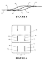
- Figure 5 shows a second embodiment of panels suitable for use as part of the garment of the invention.
- Panels 13 to 15 have an arcuate cross-section 20 that extends between two sides.
- the cross-section includes a higher area and a lower area.
- the cross-section extends through the panel from the front end to the back end providing a panel with regular cross-section.
- panel 14 overlaps both panel 13 and panel 15 in two places.
- a rivet 16 - 19 connects the two panels.
- the rivets are adapted to provide sliding engagement between the panels.
- due to the shape of the panels up to four rivets can be provided per panel. Alternatively fewer than four rivets may be used per panel, for example only two rivets may be used, each rivet for connecting the panel to a different adjacent panel.
- the garment may be provided with channels in the same way as the garment of Figure 1 . These channels also allow the panels to move relatively to each other while ensuring that the entire inner layer of the garment under the panels is covered by at least one panel.
- Figure 6 is a top view showing the panels of Figure 5 .
- a partial view of panels 14 and 15 is shown. When viewed from the top the panels appear rectangular.
- the panels may have more than one connection point to another panel along the length of the panel.
- the panels are not shown in proportion in Figure 6 and only show two connection points.
- Rivets 17, 17a, 16 and 16a are shown in Figure 6 .
- Each rivet connects two adjacent panels. As can been seen in this figure the rivets are able to slidingly move in slots 21-23. This allows the panels to slidingly move relative to each other.
- one panel is provided with a slot and the other panel with a corresponding hole for the rivet.
- both panels are provided with corresponding slots for the rivets.
- connection means between corresponding panels have been described as rivets it should be understood that any other suitable connection means that allows the panels to move slidingly with respect to each other could also be used.
- Figure 7 shows one embodiment of garment of the invention, which is a jacket or a vest.
- the garment includes rows 27-31 of panels.
- the garment begins near the shoulder 25 of a wearer and extends past the breastbone 26 and ribcage (shown as a dotted line) of the wearer.
- the garment may also extend down the back of the wearer to the buttocks of the wearer as shown in Figure 7 .
- the garment includes a plurality of rows 27-31 of panels.
- the panels are orientated in the columns in the direction of arrow 41, which corresponds to arrow 41 in Figure 6 .
- the sliding movement of panels relative to each other is therefore in the direction of arrows 41 and 42 of Figure 7 .
- the rows of panels may be arranged to overlap as shown in areas 32-35 of Figure 7 .
- areas 32 to 35 may be areas where no panels are provided.
- the garment may be provided with areas of perforations that allow air to flow through the garment. This provides breathability to the garment and prevents or reduces any insulating effects of the garment.
- the arrangement of the panels in rows also provides flexibility to the garment allowing a wearer more movement than conventional equestrian protection using foam plastics blocks.
- no perforations are provided.
- channels 36-40 are also shown in Figure 7.
- the garment is supplied with channels and each channel houses a column of panels.
- the garment is supplied with only one channel per row and the panels are attached in a sliding manner by rivets or other means as discussed with reference to Figures 2 , 5 and 6 .
- the shape of the panels may be adjusted to fit the contours of the body and the garment.
- the shape of the panels may alter around the armpits of the garment.
- foam plastics may be provided in portions of these areas to maintain the energy absorbing and spreading qualities of the garment.
- the panels may continue over the shoulders of the garment.
- the inner and outer layers of the garment are formed from fabric.
- the fabric is breathable.
- the fabric of the inner and outer layers of the garment includes one-way stretchability in the direction of arrow 42 of Figure 7 .
- the garment may include a fastening portion down one side.
- the garment may be designed to fit over the head of a wearer and then be fastened between the bottom of the garment and an armpit.
- One preferred fastening means includes Velcro in the inner layers of the complementary sides of the garment and a zip on the outer layers of the complementary sides of the garment. In this way once a wearer has placed the garment over their head the wearer pushes the Velcro together and then does the zip up.
- the garment may open at the front.
- the panels of the garment When a wearer of the garment is subject to an impact, for example by falling off a horse, the panels of the garment absorb and spread the impact energy. If the impact is of sufficient force the panels of the garment may deform. The absorbing and spreading of energy by the garment protects the wearer from the full force of the impact.
- the garments of the invention are not limited to the vest shown in Figure 7 but may be other garments for protecting other areas of the body. For example, suitably formed panels may be used in hardhats, footwear, bullet proof vests, shin, knee, elbow protection, and even eye protection.
- the panels may vary in size and shape in a garment.
- the panels may not all be the same size.
- the plates may also be arranged in different configurations in different garments. In elbow and knee protection garments, the plates may be arranged to flex around the elbows or knee.
Landscapes
- Health & Medical Sciences (AREA)
- General Health & Medical Sciences (AREA)
- Physical Education & Sports Medicine (AREA)
- Engineering & Computer Science (AREA)
- Textile Engineering (AREA)
- Professional, Industrial, Or Sporting Protective Garments (AREA)
- Polymers With Sulfur, Phosphorus Or Metals In The Main Chain (AREA)
- Aiming, Guidance, Guns With A Light Source, Armor, Camouflage, And Targets (AREA)
- Chemical Or Physical Treatment Of Fibers (AREA)
Claims (19)
- Energieabsorbierendes und/oder -verteilendes Kleidungsstück mit einer inneren Schicht (2), einer äußeren Schicht (1) und einer Mehrzahl zwischen der inneren Schicht und der äußeren Schicht des Kleidungsstücks angeordneter Elemente (3, 4, 5), dadurch gekennzeichnet, dass:die Elemente aus elastischem verformbarem Material gebildet sind und in Längsrichtung einen bogenförmigen Querschnitt aufweisen, wobei jedes Element dazu ausgelegt ist, sich relativ zu mindestens einem benachbarten Element zu verformen, zu überlappen und zu gleiten, um bei Einwirkung eines Stoßes Energie zu verteilen und/oder zu absorbierten; undwobei das Kleidungsstück ferner eine Mehrzahl von Kanälen oder Taschen umfasst, welche durch benachbarte Trennstreifenpaare zwischen der inneren Schicht und der äußeren Schicht gebildet werden, wobei die Kanäle die Elemente aufnehmen.
- Energieabsorbierendes und/oder -verteilendes Kleidungsstück nach Anspruch 1, wobei jeder Kanal oder jede Tasche dazu ausgelegt ist, eine Kolonne bogenförmiger Elemente (3, 4, 5) aufzunehmen.
- Energieabsorbierendes und/oder -verteilendes Kleidungsstück nach Anspruch 1 oder 2, wobei jedes Element (3, 4, 5) in Querschnittsform zwei niedrigere Seitenabschnitte und einen höheren mittleren Abschnitt umfasst.
- Energieabsorbierendes und/oder -verteilendes Kleidungsstück nach Anspruch 3, wobei die Elemente so angeordnet sind, dass ein Seitenabschnitt eines ersten Elements (3) neben dem mittleren Abschnitt eines zweiten Elements (4) liegt und ein Seitenabschnitt des zweiten Elements neben dem mittleren Abschnitt eines dritten Elements (5) liegt.
- Energieabsorbierendes und/oder -verteilendes Kleidungsstück nach Anspruch 3, wobei die Elemente (3, 4, 5) in einem symmetrischen Muster angeordnet sind, wobei die Symmetrieachse zwischen der Mitte der Vorderseite des Kleidungsstücks und der Mitte der Rückseite des Kleidungsstücks verläuft.
- Energieabsorbierendes und/oder -verteilendes Kleidungsstück nach Anspruch 5, wobei:ein mittleres Element (6) mit einem höheren mittleren Abschnitt und niedrigeren Seitenabschnitten sich zwischen einem ersten linksseitigen Element und einem ersten rechtsseitigen Element (5) befindet;jeweils eine Seite sowohl des ersten linksseitigen Elements als auch des ersten rechtsseitigen Elements (5) neben dem mittleren Abschnitt des mittleren Elements (6) liegt;eine Seite eines zweiten linksseitigen Elements neben der Mitte des ersten linksseitigen Elements liegt; undeine Seite eines zweigen rechtsseitigen Elements (4) neben der Mitte des ersten rechtsseitigen Elements (5) liegt.
- Energieabsorbierendes und/oder -verteilendes Kleidungsstück nach Anspruch 1 oder 2, wobei der Querschnitt jedes Elements (3, 4, 5) zwischen einer ersten Seite und einer zweigen Seite verläuft und einen höheren und niedrigeren mittleren Abschnitt umfasst.
- Energieabsorbierendes und/oder -verteilendes Kleidungsstück nach Anspruch 7, wobei:die Elemente (3, 4, 5) so angeordnet sind, dass der untere mittlere Abschnitt eines ersten Elements (3) neben einem ersten Seitenabschnitt eines zweiten Elements (4) liegt;der zweite Seitenabschnitt des ersten Elements (3) neben dem oberen mittleren Abschnitt des zweiten Elements (4) liegt;der untere mittlere Abschnitt des zweiten Elements (4) neben dem ersten Seitenabschnitt eines dritten Elements (5) liegt; undder zweite Seitenabschnitt des zweiten Elements (4) neben dem oberen mittleren Abschnitt des dritten Elements (5) liegt.
- Energieabsorbierendes und/oder -verteilendes Kleidungsstück nach einem beliebigen der Ansprüche 1 bis 8, wobei die Elemente (13, 14, 15) unter Verwendung von Nieten (16, 16a, 17, 17a) und Schlitzen (21, 22, 23, 24) gleitend miteinander in Verbindung stehen.
- Energieabsorbierendes und/oder -verteilendes Kleidungsstück nach Anspruch 9, wobei an jedem Punkt, wo Elemente (13, 14, 15) nebeneinander liegen, mindestens ein Element mit einem Schlitz versehen ist und die Elemente miteinander vernietet sind, wobei die Niete dazu ausgelegt ist, entlang dem Schlitz zu gleiten, und dadurch eine gleitende Verbindung zwischen benachbarten Elementen ermöglicht.
- Energieabsorbierendes und/oder -verteilendes Kleidungsstück nach einem beliebigen der Ansprüche 1 bis 10, wobei die Elemente so angeordnet sind, dass sie über das Kleidungsstück verlaufende Reihen (27, 28, 29, 30, 31) bilden, wobei jedes Element in der Reihe in einem Kanal aufgenommen ist oder mit dem/den benachbarten Element(en) durch ein geeignetes Gleitverbindungsmittel verbunden ist.
- Energieabsorbierendes und/oder -verteilendes Kleidungsstück nach einem beliebigen der Ansprüche 1 bis 11, wobei das Kleidungsstück mit mehr als einer Reihe Elemente versehen ist, wo Elemente Kolonnen in jedem Kanal bilden.
- Energieabsorbierendes und/oder -verteilendes Kleidungsstück nach Anspruch 12, wobei das Kleidungsstück mit einer Überlappung zwischen den Elementen in jedem Kanal versehen ist.
- Energieabsorbierendes und/oder -verteilendes Kleidungsstück nach einem beliebigen der Ansprüche 1 bis 13, wobei die Elemente aus Kunststoffen gebildet sind.
- Energieabsorbierendes und/oder -verteilendes Kleidungsstück nach Anspruch 14, wobei die Elemente aus PVC gebildet sind.
- Energieabsorbierendes und/oder -verteilendes Kleidungsstück nach einem beliebigen der Ansprüche 1 bis 15, wobei das Kleidungsstück mit Perforierungen versehen ist, um zu ermöglichen, dass Luft durch das Kleidungsstück hindurch zu dem Träger ströme.
- Energieabsorbierendes und/oder -verteilendes Kleidungsstück nach einem beliebigen der Ansprüche 1 bis 16, wobei die inneren und äußeren Schichten des Kleidungsstücks aus Stoff gebildet sind.
- Energieabsorbierendes und/oder -verteilendes Kleidungsstück nach Anspruch 17, wobei der Stoff der inneren und äußeren Schichten in einer Richtung dehnbar ist.
- Energieabsorbierendes und/oder -verteilendes Kleidungsstück nach Anspruch 18, wobei die Dehnbarkeit dazu ausgelegt ist, über das Kleidungsstück zu verlaufen,
Applications Claiming Priority (3)
| Application Number | Priority Date | Filing Date | Title |
|---|---|---|---|
| NZ52012402 | 2002-07-11 | ||
| NZ520124A NZ520124A (en) | 2002-07-11 | 2002-07-11 | Energy absorbing garment |
| PCT/NZ2003/000150 WO2004006702A1 (en) | 2002-07-11 | 2003-07-11 | Energy absorbing garment |
Publications (3)
| Publication Number | Publication Date |
|---|---|
| EP1545250A1 EP1545250A1 (de) | 2005-06-29 |
| EP1545250A4 EP1545250A4 (de) | 2006-05-17 |
| EP1545250B1 true EP1545250B1 (de) | 2010-03-03 |
Family
ID=30113409
Family Applications (1)
| Application Number | Title | Priority Date | Filing Date |
|---|---|---|---|
| EP03741694A Expired - Lifetime EP1545250B1 (de) | 2002-07-11 | 2003-07-11 | Energieabsorbierendes kleidungsstück |
Country Status (9)
| Country | Link |
|---|---|
| US (1) | US7770233B2 (de) |
| EP (1) | EP1545250B1 (de) |
| AT (1) | ATE459257T1 (de) |
| AU (1) | AU2003281187B2 (de) |
| CA (1) | CA2490762C (de) |
| DE (1) | DE60331561D1 (de) |
| NZ (1) | NZ520124A (de) |
| WO (1) | WO2004006702A1 (de) |
| ZA (1) | ZA200501025B (de) |
Families Citing this family (17)
| Publication number | Priority date | Publication date | Assignee | Title |
|---|---|---|---|---|
| US7367898B2 (en) * | 2005-02-25 | 2008-05-06 | The Aerospace Corporation | Force diversion apparatus and methods and devices including the same |
| US7461726B2 (en) | 2005-02-25 | 2008-12-09 | The Aerospace Corporation | Force diversion apparatus and methods |
| US9170071B2 (en) * | 2006-05-01 | 2015-10-27 | Warwick Mills Inc. | Mosaic extremity protection system with transportable solid elements |
| EP2207668B1 (de) | 2007-10-30 | 2014-12-10 | Warwick Mills, Inc. | Gebondete mehrlagige panzermaterialien mit weicher platte und weichem paneel |
| US8082602B2 (en) * | 2008-08-15 | 2011-12-27 | Sport Maska Inc. | Upper body protective garment |
| WO2010108133A1 (en) * | 2009-03-20 | 2010-09-23 | Warwick Mills, Inc. | Thermally vented body armor |
| US8904915B2 (en) | 2009-03-20 | 2014-12-09 | Warwick Mills, Inc. | Thermally vented body armor |
| US8291808B2 (en) | 2010-04-08 | 2012-10-23 | Warwick Mills, Inc. | Titanium mosaic body armor assembly |
| US9174111B2 (en) | 2012-07-06 | 2015-11-03 | Warrior Sports, Inc. | Protective athletic equipment |
| US9194452B2 (en) | 2012-10-31 | 2015-11-24 | The Aerospace Corporation | High stiffness vibration damping apparatus, methods and systems |
| WO2014195923A1 (en) * | 2013-06-08 | 2014-12-11 | Id Lab Inc. | Protective stretchable material and garment made therewith |
| US9907343B2 (en) * | 2014-05-23 | 2018-03-06 | Wm. T. Burnett Ip, Llc | Protective padding layer |
| US10391382B2 (en) | 2014-12-05 | 2019-08-27 | Schroth Safety Products Gmbh | Head and neck restraint device with dynamic articulation |
| US10314734B2 (en) * | 2017-01-17 | 2019-06-11 | Erick Swanson | Lumbar support plate |
| CN109349700B (zh) * | 2018-12-28 | 2021-06-04 | 浙江百先得服饰有限公司 | 一种集成式头部保护装置的立体式专用服装 |
| US12490786B2 (en) | 2020-11-11 | 2025-12-09 | Wilson Sporting Goods Co. | Chest protector |
| US12305962B1 (en) | 2022-06-24 | 2025-05-20 | Bolanle Asiyanbola | Projectile shield with enhanced projectile rebound/ricochet |
Family Cites Families (22)
| Publication number | Priority date | Publication date | Assignee | Title |
|---|---|---|---|---|
| US404493A (en) * | 1889-06-04 | Thirds to robert davis and mark curley | ||
| US4004493A (en) * | 1974-11-26 | 1977-01-25 | Vincent Costanza | Bullet proof garment |
| US4241457A (en) * | 1978-04-26 | 1980-12-30 | Klein John M | Energy impact dissolution and trauma reduction device |
| CA1212202A (en) | 1983-09-02 | 1986-10-07 | Pierre Verreault | Body protection garment |
| US5007108A (en) * | 1989-08-29 | 1991-04-16 | Sport Maska Inc. | Chest protector |
| DE3935828A1 (de) * | 1989-10-27 | 1991-05-02 | Gericke Hein Gmbh Co Kg | Wirbelsaeulenpanzer, insbesondere als unfallschutz fuer motorradfahrer |
| WO1993010419A1 (en) * | 1991-11-23 | 1993-05-27 | Dowty Armourshield Limited | Armour |
| DE4214543A1 (de) | 1992-04-29 | 1993-11-04 | Sst Sicherheits Und Systemtech | Dynamischer, teilflexibler koerperschutz gegen schlag-, schuss- und stichwaffenangriffe |
| FR2706318B1 (fr) * | 1993-06-16 | 1995-09-01 | Pascolini Jean Philippe | Dispositif pour la protection de la colonne vertébrale contre les chocs. |
| DE4341039A1 (de) * | 1993-12-02 | 1995-06-08 | Kaechele Cama Latex Gmbh | Handschuh |
| JPH0836286A (ja) | 1994-07-25 | 1996-02-06 | Konica Corp | カラー画像形成装置 |
| JPH09229598A (ja) * | 1996-02-23 | 1997-09-05 | Toray Ind Inc | 防刃材および防刃衣服 |
| US5794261A (en) * | 1997-03-12 | 1998-08-18 | Rawlings Sporting Goods Company, Inc. | Protective joint guard |
| GB2328859B (en) | 1997-09-03 | 2002-02-06 | Anthony John White | An appliance for bodily protection against injury |
| US5915528A (en) * | 1997-12-23 | 1999-06-29 | Shmuelov; Elyahu | Protective stripe assemblies with concave-convex interfaces |
| US6266818B1 (en) * | 1998-10-26 | 2001-07-31 | Warwick Mills Inc | Penetration resistant garment |
| GB9825490D0 (en) | 1998-11-21 | 1999-01-13 | Hamlett Peter E | Flexible body armour |
| JP2000283696A (ja) * | 1999-01-28 | 2000-10-13 | Unitec Japan Kk | 身体防護服 |
| AU2001254991A1 (en) * | 2000-05-19 | 2001-11-26 | Armadillo Sports Design Limited | A protective article of footwear |
| GB2368775B (en) * | 2000-11-11 | 2003-10-22 | Simon George Turner | Material for protective padding and protective clothing or equipment formed from such material |
| GB2378890A (en) | 2001-08-15 | 2003-02-26 | Michele Joanne Mancini | A protective sports glove |
| US6668385B2 (en) * | 2002-03-28 | 2003-12-30 | Stephen A. Gathings, Jr. | Adjustable insulation apparatus |
-
2002
- 2002-07-11 NZ NZ520124A patent/NZ520124A/en not_active IP Right Cessation
-
2003
- 2003-07-11 DE DE60331561T patent/DE60331561D1/de not_active Expired - Lifetime
- 2003-07-11 US US10/522,459 patent/US7770233B2/en not_active Expired - Fee Related
- 2003-07-11 EP EP03741694A patent/EP1545250B1/de not_active Expired - Lifetime
- 2003-07-11 AT AT03741694T patent/ATE459257T1/de not_active IP Right Cessation
- 2003-07-11 CA CA2490762A patent/CA2490762C/en not_active Expired - Fee Related
- 2003-07-11 AU AU2003281187A patent/AU2003281187B2/en not_active Ceased
- 2003-07-11 WO PCT/NZ2003/000150 patent/WO2004006702A1/en not_active Ceased
-
2005
- 2005-02-03 ZA ZA200501025A patent/ZA200501025B/en unknown
Also Published As
| Publication number | Publication date |
|---|---|
| WO2004006702A1 (en) | 2004-01-22 |
| EP1545250A4 (de) | 2006-05-17 |
| US20060005305A1 (en) | 2006-01-12 |
| DE60331561D1 (de) | 2010-04-15 |
| US7770233B2 (en) | 2010-08-10 |
| AU2003281187B2 (en) | 2008-05-29 |
| EP1545250A1 (de) | 2005-06-29 |
| AU2003281187A1 (en) | 2004-02-02 |
| ATE459257T1 (de) | 2010-03-15 |
| ZA200501025B (en) | 2006-07-26 |
| NZ520124A (en) | 2005-02-25 |
| CA2490762C (en) | 2012-05-08 |
| CA2490762A1 (en) | 2004-01-22 |
Similar Documents
| Publication | Publication Date | Title |
|---|---|---|
| CA2490762C (en) | Energy absorbing garment | |
| EP2445364B1 (de) | Kleidung mit einem schutzelement | |
| US4642814A (en) | Athletic padding | |
| CA2595697C (en) | Protective garment with separate inner and outer shells | |
| US4507801A (en) | Protective garment | |
| US6282724B1 (en) | Apparatus for enhancing absorption and dissipation of impact forces for all helmets and protective equipment | |
| US5887453A (en) | Protective material | |
| US5245706A (en) | Chest protector | |
| US8438669B2 (en) | Apparel incorporating a protective element | |
| US7784116B2 (en) | Padded garment | |
| US7120941B2 (en) | Crash helmet assembly | |
| US10194707B2 (en) | Apparel incorporating a protective element | |
| US20080222766A1 (en) | Athletic protective padding | |
| US20060179545A1 (en) | Athletic protective padding | |
| US20050166303A1 (en) | Head and neck protection system | |
| EP3147624B1 (de) | Bombenschutzanzug mit rückenschutz | |
| US20230232915A1 (en) | Impact absorbing pad for garment | |
| GB2493734A (en) | Armoured over-trousers | |
| US20060277644A1 (en) | Knee support system | |
| EP3050448A1 (de) | Körperprotektorlaminat | |
| JP2002194606A (ja) | 保護ベスト | |
| GB2368775A (en) | Material for protective padding | |
| US12140407B2 (en) | Deflection element and protective suit using the deflection element | |
| RU2772695C1 (ru) | Регулируемая защитная одежда для всего тела | |
| AU1638700A (en) | Body protector and garment |
Legal Events
| Date | Code | Title | Description |
|---|---|---|---|
| PUAI | Public reference made under article 153(3) epc to a published international application that has entered the european phase |
Free format text: ORIGINAL CODE: 0009012 |
|
| 17P | Request for examination filed |
Effective date: 20050209 |
|
| AK | Designated contracting states |
Kind code of ref document: A1 Designated state(s): AT BE BG CH CY CZ DE DK EE ES FI FR GB GR HU IE IT LI LU MC NL PT RO SE SI SK TR |
|
| AX | Request for extension of the european patent |
Extension state: AL LT LV MK |
|
| DAX | Request for extension of the european patent (deleted) | ||
| A4 | Supplementary search report drawn up and despatched |
Effective date: 20060403 |
|
| 17Q | First examination report despatched |
Effective date: 20070719 |
|
| GRAP | Despatch of communication of intention to grant a patent |
Free format text: ORIGINAL CODE: EPIDOSNIGR1 |
|
| GRAS | Grant fee paid |
Free format text: ORIGINAL CODE: EPIDOSNIGR3 |
|
| GRAA | (expected) grant |
Free format text: ORIGINAL CODE: 0009210 |
|
| AK | Designated contracting states |
Kind code of ref document: B1 Designated state(s): AT BE BG CH CY CZ DE DK EE ES FI FR GB GR HU IE IT LI LU MC NL PT RO SE SI SK TR |
|
| REG | Reference to a national code |
Ref country code: GB Ref legal event code: FG4D |
|
| REG | Reference to a national code |
Ref country code: CH Ref legal event code: EP |
|
| REG | Reference to a national code |
Ref country code: IE Ref legal event code: FG4D |
|
| REF | Corresponds to: |
Ref document number: 60331561 Country of ref document: DE Date of ref document: 20100415 Kind code of ref document: P |
|
| REG | Reference to a national code |
Ref country code: NL Ref legal event code: VDEP Effective date: 20100303 |
|
| REG | Reference to a national code |
Ref country code: CH Ref legal event code: NV Representative=s name: E. BLUM & CO. AG PATENT- UND MARKENANWAELTE VSP |
|
| PG25 | Lapsed in a contracting state [announced via postgrant information from national office to epo] |
Ref country code: AT Free format text: LAPSE BECAUSE OF FAILURE TO SUBMIT A TRANSLATION OF THE DESCRIPTION OR TO PAY THE FEE WITHIN THE PRESCRIBED TIME-LIMIT Effective date: 20100303 Ref country code: FI Free format text: LAPSE BECAUSE OF FAILURE TO SUBMIT A TRANSLATION OF THE DESCRIPTION OR TO PAY THE FEE WITHIN THE PRESCRIBED TIME-LIMIT Effective date: 20100303 Ref country code: SI Free format text: LAPSE BECAUSE OF FAILURE TO SUBMIT A TRANSLATION OF THE DESCRIPTION OR TO PAY THE FEE WITHIN THE PRESCRIBED TIME-LIMIT Effective date: 20100303 |
|
| PG25 | Lapsed in a contracting state [announced via postgrant information from national office to epo] |
Ref country code: SE Free format text: LAPSE BECAUSE OF FAILURE TO SUBMIT A TRANSLATION OF THE DESCRIPTION OR TO PAY THE FEE WITHIN THE PRESCRIBED TIME-LIMIT Effective date: 20100303 Ref country code: ES Free format text: LAPSE BECAUSE OF FAILURE TO SUBMIT A TRANSLATION OF THE DESCRIPTION OR TO PAY THE FEE WITHIN THE PRESCRIBED TIME-LIMIT Effective date: 20100614 Ref country code: BE Free format text: LAPSE BECAUSE OF FAILURE TO SUBMIT A TRANSLATION OF THE DESCRIPTION OR TO PAY THE FEE WITHIN THE PRESCRIBED TIME-LIMIT Effective date: 20100303 Ref country code: GR Free format text: LAPSE BECAUSE OF FAILURE TO SUBMIT A TRANSLATION OF THE DESCRIPTION OR TO PAY THE FEE WITHIN THE PRESCRIBED TIME-LIMIT Effective date: 20100604 Ref country code: NL Free format text: LAPSE BECAUSE OF FAILURE TO SUBMIT A TRANSLATION OF THE DESCRIPTION OR TO PAY THE FEE WITHIN THE PRESCRIBED TIME-LIMIT Effective date: 20100303 Ref country code: RO Free format text: LAPSE BECAUSE OF FAILURE TO SUBMIT A TRANSLATION OF THE DESCRIPTION OR TO PAY THE FEE WITHIN THE PRESCRIBED TIME-LIMIT Effective date: 20100303 Ref country code: CY Free format text: LAPSE BECAUSE OF FAILURE TO SUBMIT A TRANSLATION OF THE DESCRIPTION OR TO PAY THE FEE WITHIN THE PRESCRIBED TIME-LIMIT Effective date: 20100303 Ref country code: EE Free format text: LAPSE BECAUSE OF FAILURE TO SUBMIT A TRANSLATION OF THE DESCRIPTION OR TO PAY THE FEE WITHIN THE PRESCRIBED TIME-LIMIT Effective date: 20100303 |
|
| PG25 | Lapsed in a contracting state [announced via postgrant information from national office to epo] |
Ref country code: SK Free format text: LAPSE BECAUSE OF FAILURE TO SUBMIT A TRANSLATION OF THE DESCRIPTION OR TO PAY THE FEE WITHIN THE PRESCRIBED TIME-LIMIT Effective date: 20100303 Ref country code: BG Free format text: LAPSE BECAUSE OF FAILURE TO SUBMIT A TRANSLATION OF THE DESCRIPTION OR TO PAY THE FEE WITHIN THE PRESCRIBED TIME-LIMIT Effective date: 20100603 Ref country code: CZ Free format text: LAPSE BECAUSE OF FAILURE TO SUBMIT A TRANSLATION OF THE DESCRIPTION OR TO PAY THE FEE WITHIN THE PRESCRIBED TIME-LIMIT Effective date: 20100303 |
|
| PGFP | Annual fee paid to national office [announced via postgrant information from national office to epo] |
Ref country code: LU Payment date: 20100802 Year of fee payment: 8 |
|
| PLBE | No opposition filed within time limit |
Free format text: ORIGINAL CODE: 0009261 |
|
| STAA | Information on the status of an ep patent application or granted ep patent |
Free format text: STATUS: NO OPPOSITION FILED WITHIN TIME LIMIT |
|
| PG25 | Lapsed in a contracting state [announced via postgrant information from national office to epo] |
Ref country code: PT Free format text: LAPSE BECAUSE OF FAILURE TO SUBMIT A TRANSLATION OF THE DESCRIPTION OR TO PAY THE FEE WITHIN THE PRESCRIBED TIME-LIMIT Effective date: 20100705 Ref country code: DK Free format text: LAPSE BECAUSE OF FAILURE TO SUBMIT A TRANSLATION OF THE DESCRIPTION OR TO PAY THE FEE WITHIN THE PRESCRIBED TIME-LIMIT Effective date: 20100303 |
|
| 26N | No opposition filed |
Effective date: 20101206 |
|
| PG25 | Lapsed in a contracting state [announced via postgrant information from national office to epo] |
Ref country code: MC Free format text: LAPSE BECAUSE OF NON-PAYMENT OF DUE FEES Effective date: 20100731 |
|
| PG25 | Lapsed in a contracting state [announced via postgrant information from national office to epo] |
Ref country code: IT Free format text: LAPSE BECAUSE OF FAILURE TO SUBMIT A TRANSLATION OF THE DESCRIPTION OR TO PAY THE FEE WITHIN THE PRESCRIBED TIME-LIMIT Effective date: 20100303 |
|
| PGFP | Annual fee paid to national office [announced via postgrant information from national office to epo] |
Ref country code: CH Payment date: 20110630 Year of fee payment: 9 |
|
| PG25 | Lapsed in a contracting state [announced via postgrant information from national office to epo] |
Ref country code: HU Free format text: LAPSE BECAUSE OF FAILURE TO SUBMIT A TRANSLATION OF THE DESCRIPTION OR TO PAY THE FEE WITHIN THE PRESCRIBED TIME-LIMIT Effective date: 20100904 |
|
| PG25 | Lapsed in a contracting state [announced via postgrant information from national office to epo] |
Ref country code: TR Free format text: LAPSE BECAUSE OF FAILURE TO SUBMIT A TRANSLATION OF THE DESCRIPTION OR TO PAY THE FEE WITHIN THE PRESCRIBED TIME-LIMIT Effective date: 20100303 |
|
| REG | Reference to a national code |
Ref country code: CH Ref legal event code: PL |
|
| PG25 | Lapsed in a contracting state [announced via postgrant information from national office to epo] |
Ref country code: CH Free format text: LAPSE BECAUSE OF NON-PAYMENT OF DUE FEES Effective date: 20120731 Ref country code: LI Free format text: LAPSE BECAUSE OF NON-PAYMENT OF DUE FEES Effective date: 20120731 |
|
| PG25 | Lapsed in a contracting state [announced via postgrant information from national office to epo] |
Ref country code: LU Free format text: LAPSE BECAUSE OF NON-PAYMENT OF DUE FEES Effective date: 20110711 |
|
| PGFP | Annual fee paid to national office [announced via postgrant information from national office to epo] |
Ref country code: DE Payment date: 20130729 Year of fee payment: 11 Ref country code: IE Payment date: 20130709 Year of fee payment: 11 |
|
| PGFP | Annual fee paid to national office [announced via postgrant information from national office to epo] |
Ref country code: GB Payment date: 20130710 Year of fee payment: 11 Ref country code: FR Payment date: 20130730 Year of fee payment: 11 |
|
| REG | Reference to a national code |
Ref country code: DE Ref legal event code: R119 Ref document number: 60331561 Country of ref document: DE |
|
| GBPC | Gb: european patent ceased through non-payment of renewal fee |
Effective date: 20140711 |
|
| REG | Reference to a national code |
Ref country code: IE Ref legal event code: MM4A |
|
| REG | Reference to a national code |
Ref country code: FR Ref legal event code: ST Effective date: 20150331 |
|
| PG25 | Lapsed in a contracting state [announced via postgrant information from national office to epo] |
Ref country code: DE Free format text: LAPSE BECAUSE OF NON-PAYMENT OF DUE FEES Effective date: 20150203 |
|
| REG | Reference to a national code |
Ref country code: DE Ref legal event code: R119 Ref document number: 60331561 Country of ref document: DE Effective date: 20150203 |
|
| PG25 | Lapsed in a contracting state [announced via postgrant information from national office to epo] |
Ref country code: FR Free format text: LAPSE BECAUSE OF NON-PAYMENT OF DUE FEES Effective date: 20140731 Ref country code: GB Free format text: LAPSE BECAUSE OF NON-PAYMENT OF DUE FEES Effective date: 20140711 |
|
| PG25 | Lapsed in a contracting state [announced via postgrant information from national office to epo] |
Ref country code: IE Free format text: LAPSE BECAUSE OF NON-PAYMENT OF DUE FEES Effective date: 20140711 |