EP1545152A2 - Verfahren und Geräte zur Rückkopplungsannulierung - Google Patents
Verfahren und Geräte zur Rückkopplungsannulierung Download PDFInfo
- Publication number
- EP1545152A2 EP1545152A2 EP03076370A EP03076370A EP1545152A2 EP 1545152 A2 EP1545152 A2 EP 1545152A2 EP 03076370 A EP03076370 A EP 03076370A EP 03076370 A EP03076370 A EP 03076370A EP 1545152 A2 EP1545152 A2 EP 1545152A2
- Authority
- EP
- European Patent Office
- Prior art keywords
- filter
- hearing aid
- output
- signal
- feedback
- Prior art date
- Legal status (The legal status is an assumption and is not a legal conclusion. Google has not performed a legal analysis and makes no representation as to the accuracy of the status listed.)
- Withdrawn
Links
Images


Classifications
-
- H—ELECTRICITY
- H04—ELECTRIC COMMUNICATION TECHNIQUE
- H04R—LOUDSPEAKERS, MICROPHONES, GRAMOPHONE PICK-UPS OR LIKE ACOUSTIC ELECTROMECHANICAL TRANSDUCERS; ELECTRIC HEARING AIDS; PUBLIC ADDRESS SYSTEMS
- H04R25/00—Electric hearing aids
- H04R25/45—Prevention of acoustic reaction, i.e. acoustic oscillatory feedback
- H04R25/453—Prevention of acoustic reaction, i.e. acoustic oscillatory feedback electronically
-
- H—ELECTRICITY
- H04—ELECTRIC COMMUNICATION TECHNIQUE
- H04R—LOUDSPEAKERS, MICROPHONES, GRAMOPHONE PICK-UPS OR LIKE ACOUSTIC ELECTROMECHANICAL TRANSDUCERS; ELECTRIC HEARING AIDS; PUBLIC ADDRESS SYSTEMS
- H04R25/00—Electric hearing aids
- H04R25/50—Customised settings for obtaining desired overall acoustical characteristics
- H04R25/505—Customised settings for obtaining desired overall acoustical characteristics using digital signal processing
-
- H—ELECTRICITY
- H04—ELECTRIC COMMUNICATION TECHNIQUE
- H04R—LOUDSPEAKERS, MICROPHONES, GRAMOPHONE PICK-UPS OR LIKE ACOUSTIC ELECTROMECHANICAL TRANSDUCERS; ELECTRIC HEARING AIDS; PUBLIC ADDRESS SYSTEMS
- H04R29/00—Monitoring arrangements; Testing arrangements
- H04R29/004—Monitoring arrangements; Testing arrangements for microphones
- H04R29/005—Microphone arrays
- H04R29/006—Microphone matching
Definitions
- the present invention relates to apparatus and methods for canceling feedback in audio systems such as hearing aids.
- venting the BTE earmold or ITE shell establishes an acoustic feedback path that limits the maximum possible gain to less than 40 dB for a small vent and even less for large vents (Kates, J.M., "A computer simulation of hearing aid response and the effects of ear canal size", J. Acoust. Soc. Am., Vol. 83, pp 1952-1963, 1988).
- the acoustic feedback path includes the effects of the hearing-aid amplifier, receiver, and microphone as well as the vent acoustics.
- a more effective technique is feedback cancellation, in which the feedback signal is estimated and subtracted from the microphone signal.
- Computer simulations and prototype digital systems indicate that increases in gain of between 6 and 17 dB can be achieved in an adaptive system before the onset of oscillation, and no loss of high-frequency response is observed (Bustamante, D.K., Worrell, T.L., and Williamson, M.J., "Measurement of adaptive suppression of acoustic feedback in hearing aids", Proc. 1989 Int. Conf. Acoust. Speech and Sig.
- the characteristics of the feedback path are estimated using a noise sequence continuously injected at a low level (Engebretson and French-St. George, 1993; Bisgaard, 1993, referenced above).
- the weight update of the adaptive filter also proceeds on a continuous basis, generally using the LMS algorithm (Widrow, B., McCool, J.M., Larimore, M.G., and Johnson, C.R., Jr., "Stationary and nonstationary learning characteristics of the LMS adaptive filter", Proc. IEEE, Vol. 64, pp 1151-1162, 1976). This approach results in a reduced SNR for the user due to the presence of the injected probe noise.
- the ability of the system to cancel the feedback may be reduced due to the presence of speech or ambient noise at the microphone input (Kates, 1991, referenced above; Maxwell, J.A., and Zurek, P.M., "Reducing acoustic feedback in hearing aids", IEEE Trans. Speech and Audio Proc., Vol. 3, pp 304-313, 1995).
- Better estimation of the feedback path will occur if the hearing-aid processing is turned off during the adaptation so that the instrument is operating in an open-loop rather than closed-loop mode while adaptation occurs (Kates, 1991).
- Wiener-Hopf equation for a short noise burst used as the probe in an open-loop system, solving the Wiener-Hopf equation (Makhoul, J. "Linear prediction: A tutorial review," Proc.
- the primary objective of the feedback cancellation processing of the present invention is to eliminate "whistling" due to feedback in an unstable hearing-aid amplification system.
- the processing should provide an additional 10 dB of allowable gain in comparison with a system not having feedback cancellation.
- the presence of feedback cancellation should not introduce any artifacts in the hearing-aid output, and it should not require any special understanding on the part of the user to operate the system.
- the feedback cancellation of the present invention uses a cascade of two adaptive filters along with a short bulk delay.
- the first filter is adapted when the hearing aid is turned on in the ear. This filter adapts quickly using a white noise probe signal, and then the filter coefficients are frozen.
- the first filter models those parts of the hearing-aid feedback path that are assumed to be essentially constant while the hearing aid is in use, such as the microphone, amplifier, and receiver resonances, and the basic acoustic feedback path.
- the second filter adapts while the hearing aid is in use and does not use a separate probe signal.
- This filter provides a rapid correction to the feedback path model when the hearing aid goes unstable, and more slowly tracks perturbations in the feedback path that occur in daily use such as caused by chewing, sneezing, or using a telephone handset.
- the bulk delay shifts the filter response so as to make the most effective use of the limited number of filter coefficients.
- a hearing aid comprises a microphone for converting sound into an audio signal, feedback cancellation means including means for estimating a physical feedback signal of the hearing aid, and means for modelling a signal processing feedback signal to compensate for the estimated physical feedback signal, subtracting means, connected to the output of the microphone and the output of the feedback cancellation means, for subtracting the signal processing feedback signal from the audio signal to form a compensated audio signal, a hearing aid processor, connected to the output of the subtracting means, for processing the compensated audio signal, and a speaker, connected to the output of the hearing aid processor, for converting the processed compensated audio signal into a sound signal.
- the feedback cancellation means forms a feedback path from the output of the hearing aid processing means to the input of the subtracting means and includes a first filter for modeling near constant factors in the physical feedback path, and a second, quickly varying, filter for modeling variable factors in the feedback path.
- the first filter varies substantially slower than the second filter.
- the first filter is designed when the hearing aid is turned on and the design is then frozen.
- the second filter is also designed when the hearing aid is turned on, and adapted thereafter based upon the output of the subtracting means and based upon the output of the hearing aid processor.
- the first filter may be the denominator of an IIR filter and the second filter may be the numerator of said IIR filter.
- the first filter is connected to the output of the hearing aid processor, for filtering the output of the hearing aid processor, and the output of the first filter is connected to the input of the second filter, for providing the filtered output of the hearing aid processor to the second filter.
- the first filter might be an IIR filter and the second filter an FIR filter.
- the means for designing the first filter and the means for designing the second filter comprise means for disabling the input to the speaker means from the hearing aid processing means, a probe for providing a test signal to the input of the speaker means and to the second filter, means for connecting the output of the microphone to the input of the first filter, means for connecting the output of the first filter and the output of the second filter to the subtraction means, means for designing the second filter based upon the test signal and the output of the subtraction means, and means for designing the first filter based upon the output of the microphone and the output of the subtraction means.
- the means for designing the first filter may further include means for detuning the filter, and the means for designing the second filter may further include means for adapting the second filter to the detuned first filter.
- the hearing aid includes means for designing the first filter when the hearing aid is turned on, means for designing the second filter when the hearing aid is turned on, means for slowly adapting the first filter, and means for rapidly adapting the second filter based upon the output of the subtracting means and based upon the output of the hearing aid processing means.
- the means for adapting the first filter might adapts the first filter based upon the output of the subtracting means, or based upon the output of the hearing aid processing means.
- a dual microphone embodiment of the present invention hearing aid comprises a first microphone for converting sound into a first audio signal, a second microphone for converting sound into a second audio signal, feedback cancellation means including means for estimating physical feedback signals to each microphone of the hearing aid, and means for modelling a first signal processing feedback signal to compensate for the estimated physical feedback signal to the first microphone and a second signal processing feedback signal to compensate for the estimated physical feedback signal to the second microphone, means for subtracting the first signal processing feedback signal from the first audio signal to form a first compensated audio signal, means for subtracting the second signal processing feedback signal from the second audio signal to form a second compensated audio signal, beamforming means, connected to each subtracting means, to combine the compensated audio signals into a beamformed signal, a hearing aid processor, connected to the beamforming means, for processing the beamformed signal, and a speaker, connected to the output of the hearing aid processing means, for converting the processed beamformed signal into a sound signal.
- the feedback cancellation means includes a slower varying filter, connected to the output of the hearing aid processing means, for modeling near constant environmental factors in one of the physical feedback paths, a first quickly varying filter, connected to the output of the slower varying filter and providing an input to the first subtraction means, for modeling variable factors in the first feedback path, and a second quickly varying filter, connected to the output of the slowly varying filter and providing an input to the second subtraction means, for modeling variable factors in the second feedback path.
- the slower varying filter varies substantially slower than said quickly varying filters.
- the hearing aid further includes means for designing the slower varying filter when the hearing aid is turned on, and means for freezing the slower varying filter design. It also includes means for designing the first and second quickly varying filters when the hearing aid is turned on, means for adapting the first quickly varying filter based upon the output of the first subtracting means and based upon the output of the hearing aid processing means, and means for adapting the second quickly varying filter based upon the output of the second subtracting means and based upon the output of the hearing aid processing means.
- the first quickly varying filter might be the denominator of a first IIR filter
- the second quickly varying filter might be the denominator of a second IIR filter
- the slower varying filter might be based upon the numerator of at least one of these IIR filters.
- the slower varying filter might be an IIR filter and the rapidly varying filters might be FIR filters.
- the means for designing the slower varying filter and the means for designing the rapidly varying filters might comprise means for disabling the input to the speaker means from the hearing aid processing means, probe means for providing a test signal to the input of the speaker means and to the rapidly varying filters, means for connecting the output of the first microphone to the input of the slower varying filter, means for connecting the output of the slower varying filter and the output of the first rapidly varying filter to the first subtraction means, means for designing the first rapidly varying filter based upon the test signal and the output of the first subtraction means, means for connecting the output of the slower varying filter and the output of the second rapidly varying filter to the second subtraction means, means for designing the second rapidly varying filter based upon the test signal and the output of the second subtraction means, and means for designing the slower varying filter based upon the output of the microphone and the output of at least one of the subtraction means.
- the means for designing the slower varying filter might further include means for detuning the slower varying filter
- the means for designing the quickly varying filters might further include means for adapting the quickly varying filters to the detuned slower varying filter.
- Another vesrion of the dual microphone embodiment might include means for designing the slower varying filter when the hearing aid is turned on, means for designing the quickly varying filters when the hearing aid is turned on, means for slowly adapting the slower varying filter, means for rapidly adapting the first quickly varying filter based upon the output of the first subtracting means and based upon the output of the hearing aid processing means, and means for rapidly adapting the second quickly varying filter based upon the output of the second subtracting means and based upon the output of the hearing aid processing means.
- the means for adapting the slower varying filter might adapt the slower varying filter based upon the output of at least one of the subtracting means, or might adapt the slower varying filter based upon the output of the hearing aid processing means.
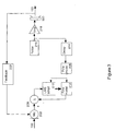
- FIG. 1 is a flow diagram showing the operation of a hearing aid according to the present invention.
- step 12 the wearer of the hearing aid turns the hearing aid on.
- Step 14 and 16 comprise the start-up processing operations, and step 18 comprises the processing when the hearing aid is in use.
- the feedback cancellation uses an adaptive filter, such as an IIR filter, along with a short bulk delay.
- the filter is designed when the hearing aid is turned on in the ear.
- the filter preferably comprising an IIR filter with adapting numerator and denominator portions, is designed.
- the denominator portion of the IIR filter is preferably frozen.
- the numerator portion of the filter now a FIR filter, still adapts.
- the initial zero coefficients are modified to compensate for changes to the pole coefficients in step 14.
- the hearing aid is turned on and operates in closed loop.
- the zero (FIR) filter consisting of the numerator of the IIR filter developed during start-up, continues to adapt in real time.
- step 14 the IIR filter design starts by exciting the system with a short white-noise burst, and cross-correlating the error signal with the signal at the microphone and with the noise which was injected just ahead of the amplifier.
- the normal hearing-aid processing is turned off so that the open-loop system response can be obtained, giving the most accurate possible model of the feedback path.
- the cross-correlation is used for LMS adaptation of the pole and zero filters modeling the feedback path using the equation-error approach (Ho, K.C. and Chan, Y.T., "Bias removal in equation-error adaptive IIR filters", IEEE Trans. Sig. Proc., Vol. 43, pp 51-62, 1995).
- step 14 The poles are then detuned to reduce the filter Q values in order to provide for robustness in dealing in shifts in the resonant system behavior that may occur in the feedback path.
- the operation of step 14 is shown in more detail in Figure 2. After step 14, the pole filter coefficients are frozen.
- step 16 the system is excited with a second noise burst, and the output of the all-pole filter is used in series with the zero filter.
- LMS adaptation is used to adapt the model zero coefficients to compensate for the changes made in detuning the pole coefficients.
- the LMS adaptation yields the optimal numerator of the IIR filter given the detuned poles.
- the operation of step 16 is shown in more detail in Figure 3. Note that the changes in the zero coefficients that occur in step 16 are in general very small. Thus step 16 may be eliminated with only a slight penalty in system performance.
- the pole filter models those parts of the hearing-aid feedback path that are assumed to be essentially constant while the hearing aid is in use, such as the microphone, amplifier, and receiver resonances, and the resonant behavior of the basic acoustic feedback path.
- Step 18 comprises all of the running operations taking place in the hearing aid.
- Running operations include the following:
- audio input 100 for example from the hearing aid microphone (not shown) after subtraction of a cancellation signal 120 (described below), is processed by hearing aid processing 106 to generate audio output 150, which is delivered to the hearing aid amplifier (not shown), and signal 108.
- Signal 108 is delayed by delay 110, which shifts the filter response so as to make the most effective use of the limited number of zero filter coefficients, filtered by all-pole filter 114, and filtered by FIR filter 118 to form a cancellation signal 120, which is subtracted from input signal 100 by adder 102.
- Optional adaptive signal 112 is shown in case pole filter 114 is not frozen, but rather varies slowly, responsive to adaptive signal 112 based upon error signal 104, feedback signal 108, or the like.
- FIR filter 118 adapts while the hearing aid is in use, without the use of a separate probe signal.
- the FIR filter coefficients are generated in LMS adapt block 122 based upon error signal 104 (out of adder 102) and input 116 from all-pole filter 114.
- FIR filter 118 provides a rapid correction to the feedback path when the hearing aid goes unstable, and more slowly tracks perturbations in the feedback path that occur in daily use such as caused by chewing, sneezing, or using a telephone handset.
- the operation of step 18 is shown in more detail in the alternative embodiments of Figures 4 and 6.
- the user will notice some differences in hearing-aid operation resulting from the feedback cancellation.
- the first difference is the request that the user turn the hearing aid on in the ear, in order to have the IIR filter correctly configured.
- the second difference is the noise burst generated at start-up.
- the user will hear a 500-msec burst of white noise at a loud conversational speech level.
- the noise burst is a potential annoyance for the user, but the probe signal is also an indicator that the hearing aid is working properly.
- hearing aid users may well find it reassuring to hear the noise; it gives proof that the hearing aid is operating, much like hearing the sound of the engine when starting an automobile.
- the user Under normal operating conditions, the user will not hear any effect of the feedback cancellation.
- the feedback cancellation will slowly adapt to changes in the feedback path and will continuously cancel the feedback signal. Successful operation of the feedback cancellation results in an absence of problems that otherwise would have occurred.
- the user will be able to choose approximately 10 dB more gain than without the feedback cancellation, resulting in higher signal levels and potentially better speech intelligibility if the additional gain results in more speech sounds being elevated above the impaired auditory threshold. But as long as the operating conditions of the hearing aid remain close to those present when it was turned on, there will be very little obvious effect of the feedback cancellation functioning.
- An extreme change in the feedback path may drive the system beyond the ability of the adaptive cancellation filter to provide compensation. If this happens, the user (or those nearby) will notice continuous or intermittent whistling.
- a potential solution to this problem is for the user to turn the hearing aid off and then on again in the ear. This will generate a noise burst just as when the hearing aid was first turned on, and a new feedback cancellation filter will be designed to match the new feedback path.
- FIGs 2 and 3 show the details of start-up processing steps 14 and 16 of Figure 1.
- the IIR filter is designed when the hearing aid is inserted into the ear. Once the filter is designed, the pole filter coefficients are saved and no further pole filter adaptation is performed. If a complete set of new IIR filter coefficients is needed due to a substantial change in the feedback path, it can easily be generated by turning the hearing aid off and then on again in the ear.
- the filter poles are intended to model those aspects of the feedback path that can have high- Q resonances but which stay relatively constant during the course of the day. These elements include the microphone 202, power amplifier 218, receiver 220, and the basic acoustics of feedback path 222.
- the IIR filter design proceeds in two stages. In the first stage the initial filter pole and zero coefficients are computed. A block diagram is shown in Figure 2. The hearing aid processing is turned off, and white noise probe signal q(n) 216 is injected into the system instead. During the 250-msec noise burst, the poles and zeroes of the entire system transfer function are determined using an adaptive equation-error procedure.
- the system transfer function being modeled consists of the series combination of the amplifier 218, receiver 220, acoustic feedback path 222, and microphone 202.
- the equation-error procedure uses the FIR filter 206 after the microphone to cancel the poles of the system transfer function, and uses the FIR filter 212 to duplicate the zeroes of the system transfer function.
- the delay 214 represents the broadband delay in the system.
- the filters 206 and 212 are simultaneously adapted during the noise burst using an LMS algorithm 204, 210.
- the objective of the adaptation is to minimize the error signal produced at the output of summation 208.
- minimizing the error signal generates an optimum model of the poles and zeroes of the system transfer function.
- a 7-pole/7-zero filter is used.
- the poles of the transfer function model once determined, are modified and then frozen.
- the transfer function of the pole portion of the IIR model is given by where K is the number of poles in the model. If the Q of the poles is high, then a small shift in one of the system resonance frequencies could result in a large mismatch between the output of the model and the actual feedback path transfer function. The poles of the model are therefore modified to reduce the possibility of such a mismatch.
- the poles, once found, are detuned by multiplying the filter coefficients ⁇ a k ⁇ by the factor p k , 0 ⁇ p ⁇ 1. This operation reduces the filter Q values by shifting the poles inward from the unit circle in the complex-z plane.
- the pole coefficients are now frozen and undergo no further changes.
- the zeroes of the IIR filter are adapted to correspond to the modified poles.
- a block diagram of this operation is shown in Figure 3.
- the white noise probe signal 216 is injected into the system for a second time, again with the hearing aid processing turned off.
- the probe is filtered through delay 214 and thence through the frozen pole model filter 206 which represents the denominator of the modeled system transfer function.
- the pole coefficients in filter 206 have been detuned as described in the paragraph above to lower the Q values of the modeled resonances.
- the zero coefficients in filter 212 are now adapted to reduce the error between the actual feedback system transfer function and the modeled system incorporating the detuned poles.
- the objective of the adaptation is to minimize the error signal produced at the output of summation 208.
- the LMS adaptation algorithm 210 is again used. Because the zero coefficients computed during the first noise burst are already close to the desired values, the second adaptation will converge quickly.
- the complete IIR filter transfer function is then given by where M is the number of zeroes in the filter. In many instances, the second adaptation produces minimal changes in the zero filter coefficients. In these cases the second stage can be safely eliminated.
- FIG 4 is a block diagram showing the hearing aid operation of step 18 of Figure 1, including the running adaptation of the zero filter coefficients, in a first embodiment of the present invention.
- the series combination of the frozen pole filter 206 and the zero filter 212 gives the model transfer function G(z) determined during start-up.
- the coefficients of the zero model filter 212 are initially set to the values developed during step 14 of the start-up procedure, but are then allowed to adapt.
- the coefficients of the pole model filter 206 are kept at the values established during start-up and no further adaptation of these values takes place during normal hearing aid operation.
- the hearing-aid processing is then turned on and the zero model filter 212 is allowed to continuously adapt in response to changes in the feedback path as will occur, for example, when a telephone handset is brought up to the ear.
- the inputs to the summation 208 are the signal from the microphone 202, and the feedback cancellation signal produced by the cascade of the delay 214 with the all-pole model filter 206 in series with the zero model filter 212.
- the zero filter coefficients are updated using LMS adaptation in block 210.
- the weight update for block operation of the LMS algorithm is formed by taking the average of the weight updates for each sample within the block.
- FIG. 5 is a flow diagram showing the operation of a hearing aid having multiple input microphones.
- the wearer of the hearing aid turns the hearing aid on.
- Step 564 and 566 comprise the start-up processing operations
- step 568 comprises the running operations as the hearing aid operates.
- Steps 562, 564, and 566 are similar to steps 14, 16, and 18 in Figure 1.
- Step 568 is similar to step 18, except that the signals from two or more microphones arc combined to form audio signal 504, which is processed by hearing aid processing 506 and used as an input to LMS adapt block 522.
- the feedback cancellation uses an adaptive filter, such as an IIR filter, along with a short bulk delay.
- the filter is designed when the hearing aid is turned on in the ear.
- the IIR filter is designed.
- the denominator portion of the IIR filter is frozen, while the numerator portion of the filter still adapts.
- the initial zero coefficients are modified to compensate for changes to the pole coefficients in step 564.
- the hearing aid is turned on and operates in closed loop.
- the zero (FIR) filter consisting of the numerator of the IIR filter developed during start-up, continues to adapt in real time.
- audio input 500 from two or more hearing aid microphones (not shown) after subtraction of a cancellation signal 520, is processed by hearing aid processing 506 to generate audio output 550, which is delivered to the hearing aid amplifier (not shown), and signal 508.
- Signal 508 is delayed by delay 510, which shifts the filter response so as to make the most effective use of the limited number of zero filter coefficients, filtered by all-pole filter 514, and filtered by FIR filter 518 to form a cancellation signal 520, which is subtracted from input signal 500 by adder 502.
- FIR filter 518 adapts while the hearing aid is in use, without the use of a separate probe signal.
- the FIR filter coefficients are generated in LMS adapt block 522 based upon error signal 504 (out of adder 502) and input 516 from all-pole filter 514. All-pole filter 514 may be frozen, or may adapt slowly based upon input 512 (which might be based upon the output(s) of adder 502 or signal 508).
- Figure 6 is a block diagram showing the processing of step 568 of Figure 5, including running adaptation of the FIR filter weights, in a second embodiment of the present invention, for use with two microphones 602 and 603.
- the purpose of using two or more microphones in the hearing aid is to allow adaptive or switchable directional microphone processing.
- the hearing aid could amplify the sound signals coming from in front of the wearer while attenuating sounds coming from behind the wearer.
- Figure 6 shows a preferred embodiment of a two input (600, 601) hearing aid according to the present invention. This embodiment is very similar to that shown in Figure 4, and elements having the same reference number are the same.
- feedback 222, 224 is canceled at each of the microphones 602, 603 separately before the beamforming processing stage 650 instead of trying to cancel the feedback after the beamforming output to hearing aid 402.
- This approach is desired because the frequency response of the acoustic feedback path at the beamforming output could be affected by the changes in the beam directional pattern.
- Beamforming 650 is a simple and well known process. Beam form block 650 selects the output of one of the omnidirectional microphones 602, 603 if a nondirectional sensitivity pattern is desired. In a noisy situation, the output of the second (rear) microphone is subtracted from the first (forward) microphone to create a directional (cardioid) pattern having a null towards the rear.
- the system shown in Figure 6 will work for any combination of microphone outputs 602 and 603 used to form the beam.
- the coefficients of the zero model filters 612, 613 are adapted by LMS adapt blocks 610, 611 using the error signals produced at the outputs of summations 609 and 608, respectively.
- the same pole model filter 606 is preferably used for both microphones. It is assumed in this approach that the feedback paths at the two microphones will be quite similar, having similar resonance behavior and differing primarily in the time delay and local reflections at the two microphones. If the pole model filter coefficients are designed for the microphone having the shortest time delay (closest to the vent opening in the earmold), then the adaptive zero model filters 612, 613 should be able to compensate for the small differences between the microphone positions and errors in microphone calibration.
- the price paid for this feedback cancellation approach is an increase in the computational burden, since two adaptive zero model filters 612 and 613 must be maintained instead of just one. If 7 coefficients are used for the pole model filter 606, and 8 coefficients used for each LMS adaptive zero model filter 612 and 613, then the computational requirements go from about 0.4 MIPS for a single adaptive FIR filter to 0.65 MIPS when two are used.
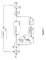
- FIG. 7 is a block diagram showing the running adaptation of a third embodiment of the present invention, utilizing an adaptive FIR filter 702 and a frozen IIR filter 701.
- This embodiment is not as efficient as the embodiment of Figure 1-4, but will accomplish the same purpose.
- Initial filter design of IIR filter 701 and FIR filter 702 is accomplished is very similar to the process shown in Figure 1, except that step 14 designs the poles and zeroes of FIR filter 702, which are detuned and frozen, and step 16 designs FIR filter 702. In step 18, all of IIR filter 701 is frozen, and FIR filter 702 adapts as shown.
- Figure 8 is a plot of the error signal during initial adaptation, for the embodiment of Figures 1-4.
- the figure shows the error signal 104 during 500 msec of initial adaptation.
- the equation-error formulation is being used, so the pole and zero coefficients are being adapted simultaneously in the presence of white noise probe signal 216.
- the IIR feedback path model consists of 4 poles and 7 zeroes, with a bulk delay adjusted to compensate for the delay in the block processing. These data are from a real-time implementation using a Motorola 56000 family processor embedded in an AudioLogic Audallion and connected to a Danavox behind the ear (BTE) hearing aid. The hearing aid was connected to a vented earmold mounted on a dummy head. Approximately 12 dB of additional gain was obtained using the adaptive feedback cancellation design of Figures 1-4.
- Figure 9 is a plot of the frequency response of the IIR filter after initial adaptation, for the embodiment of Figures 1-4.
- the main peak at 4 KHz is the resonance of the receiver (output transducer) in the hearing aid.
- the frequency response shown in Figure 9 is typical of hearing aid, having a wide dynamic range and expected shape and resonant value.
Landscapes
- Health & Medical Sciences (AREA)
- General Health & Medical Sciences (AREA)
- Neurosurgery (AREA)
- Otolaryngology (AREA)
- Physics & Mathematics (AREA)
- Engineering & Computer Science (AREA)
- Acoustics & Sound (AREA)
- Signal Processing (AREA)
- Circuit For Audible Band Transducer (AREA)
- Soundproofing, Sound Blocking, And Sound Damping (AREA)
- External Artificial Organs (AREA)
- Gas Separation By Absorption (AREA)
- General Induction Heating (AREA)
- Orthopedics, Nursing, And Contraception (AREA)
- Electrostatic, Electromagnetic, Magneto- Strictive, And Variable-Resistance Transducers (AREA)
- Filters That Use Time-Delay Elements (AREA)
- Treating Waste Gases (AREA)
Applications Claiming Priority (3)
| Application Number | Priority Date | Filing Date | Title |
|---|---|---|---|
| US972265 | 1978-12-22 | ||
| US08/972,265 US6072884A (en) | 1997-11-18 | 1997-11-18 | Feedback cancellation apparatus and methods |
| EP98956651A EP1033063B1 (de) | 1997-11-18 | 1998-11-07 | Vorrichtung und verfahren zur rückkopplungsunterdrückung |
Related Parent Applications (1)
| Application Number | Title | Priority Date | Filing Date |
|---|---|---|---|
| EP98956651A Division EP1033063B1 (de) | 1997-11-18 | 1998-11-07 | Vorrichtung und verfahren zur rückkopplungsunterdrückung |
Publications (2)
| Publication Number | Publication Date |
|---|---|
| EP1545152A2 true EP1545152A2 (de) | 2005-06-22 |
| EP1545152A3 EP1545152A3 (de) | 2005-08-31 |
Family
ID=25519430
Family Applications (2)
| Application Number | Title | Priority Date | Filing Date |
|---|---|---|---|
| EP03076370A Withdrawn EP1545152A3 (de) | 1997-11-18 | 1998-11-07 | Verfahren und Geräte zur Rückkopplungsannulierung |
| EP98956651A Expired - Lifetime EP1033063B1 (de) | 1997-11-18 | 1998-11-07 | Vorrichtung und verfahren zur rückkopplungsunterdrückung |
Family Applications After (1)
| Application Number | Title | Priority Date | Filing Date |
|---|---|---|---|
| EP98956651A Expired - Lifetime EP1033063B1 (de) | 1997-11-18 | 1998-11-07 | Vorrichtung und verfahren zur rückkopplungsunterdrückung |
Country Status (7)
| Country | Link |
|---|---|
| US (1) | US6072884A (de) |
| EP (2) | EP1545152A3 (de) |
| AT (1) | ATE239347T1 (de) |
| AU (1) | AU1312399A (de) |
| DE (1) | DE69814142T2 (de) |
| DK (1) | DK1033063T3 (de) |
| WO (1) | WO1999026453A1 (de) |
Cited By (1)
| Publication number | Priority date | Publication date | Assignee | Title |
|---|---|---|---|---|
| WO2008064453A1 (en) * | 2006-11-29 | 2008-06-05 | Gennum Corporation | Hearing instrument with acoustic blocker, in-the-ear microphone and speaker |
Families Citing this family (132)
| Publication number | Priority date | Publication date | Assignee | Title |
|---|---|---|---|---|
| US6885752B1 (en) | 1994-07-08 | 2005-04-26 | Brigham Young University | Hearing aid device incorporating signal processing techniques |
| US6434246B1 (en) * | 1995-10-10 | 2002-08-13 | Gn Resound As | Apparatus and methods for combining audio compression and feedback cancellation in a hearing aid |
| US6498858B2 (en) * | 1997-11-18 | 2002-12-24 | Gn Resound A/S | Feedback cancellation improvements |
| US6201875B1 (en) | 1998-03-17 | 2001-03-13 | Sonic Innovations, Inc. | Hearing aid fitting system |
| US7254199B1 (en) * | 1998-09-14 | 2007-08-07 | Massachusetts Institute Of Technology | Location-estimating, null steering (LENS) algorithm for adaptive array processing |
| JP2002530922A (ja) | 1998-11-13 | 2002-09-17 | ビットウェイブ・プライベイト・リミテッド | 信号を処理する装置と方法 |
| US6380892B1 (en) * | 1999-04-02 | 2002-04-30 | Lg Information & Communications, Ltd. | Adaptive beamforming method in an IMT-2000 system |
| US6408318B1 (en) | 1999-04-05 | 2002-06-18 | Xiaoling Fang | Multiple stage decimation filter |
| US6434247B1 (en) * | 1999-07-30 | 2002-08-13 | Gn Resound A/S | Feedback cancellation apparatus and methods utilizing adaptive reference filter mechanisms |
| ES2235937T3 (es) | 1999-09-10 | 2005-07-16 | Starkey Laboratories, Inc. | Procesado de señales de audio. |
| US6480610B1 (en) * | 1999-09-21 | 2002-11-12 | Sonic Innovations, Inc. | Subband acoustic feedback cancellation in hearing aids |
| AU2005203487B2 (en) * | 1999-11-22 | 2007-08-30 | Brigham Young University | Hearing aid device incorporating signal processing techniques |
| US7558391B2 (en) * | 1999-11-29 | 2009-07-07 | Bizjak Karl L | Compander architecture and methods |
| US6757395B1 (en) | 2000-01-12 | 2004-06-29 | Sonic Innovations, Inc. | Noise reduction apparatus and method |
| US6313773B1 (en) | 2000-01-26 | 2001-11-06 | Sonic Innovations, Inc. | Multiplierless interpolator for a delta-sigma digital to analog converter |
| US6831986B2 (en) * | 2000-12-21 | 2004-12-14 | Gn Resound A/S | Feedback cancellation in a hearing aid with reduced sensitivity to low-frequency tonal inputs |
| DE10110258C1 (de) * | 2001-03-02 | 2002-08-29 | Siemens Audiologische Technik | Verfahren zum Betrieb eines Hörhilfegerätes oder Hörgerätesystems sowie Hörhilfegerät oder Hörgerätesystem |
| US6671379B2 (en) * | 2001-03-30 | 2003-12-30 | Think-A-Move, Ltd. | Ear microphone apparatus and method |
| US6647368B2 (en) | 2001-03-30 | 2003-11-11 | Think-A-Move, Ltd. | Sensor pair for detecting changes within a human ear and producing a signal corresponding to thought, movement, biological function and/or speech |
| US6717537B1 (en) | 2001-06-26 | 2004-04-06 | Sonic Innovations, Inc. | Method and apparatus for minimizing latency in digital signal processing systems |
| US7277554B2 (en) | 2001-08-08 | 2007-10-02 | Gn Resound North America Corporation | Dynamic range compression using digital frequency warping |
| US7346175B2 (en) * | 2001-09-12 | 2008-03-18 | Bitwave Private Limited | System and apparatus for speech communication and speech recognition |
| US20030187527A1 (en) * | 2002-03-28 | 2003-10-02 | International Business Machines Corporation | Computer-based onboard noise suppression devices with remote web-based management features |
| DE10228632B3 (de) † | 2002-06-26 | 2004-01-15 | Siemens Audiologische Technik Gmbh | Richtungshören bei binauraler Hörgeräteversorgung |
| US20040024596A1 (en) * | 2002-07-31 | 2004-02-05 | Carney Laurel H. | Noise reduction system |
| DE10242700B4 (de) * | 2002-09-13 | 2006-08-03 | Siemens Audiologische Technik Gmbh | Rückkopplungskompensator in einem akustischen Verstärkungssystem, Hörhilfsgerät, Verfahren zur Rückkopplungskompensation und Anwendung des Verfahrens in einem Hörhilfsgerät |
| DE10244184B3 (de) * | 2002-09-23 | 2004-04-15 | Siemens Audiologische Technik Gmbh | Feedbackkompensation für Hörgeräte mit Systemabstandsschätzung |
| US7092532B2 (en) * | 2003-03-31 | 2006-08-15 | Unitron Hearing Ltd. | Adaptive feedback canceller |
| US7809150B2 (en) * | 2003-05-27 | 2010-10-05 | Starkey Laboratories, Inc. | Method and apparatus to reduce entrainment-related artifacts for hearing assistance systems |
| US7756276B2 (en) * | 2003-08-20 | 2010-07-13 | Phonak Ag | Audio amplification apparatus |
| AU2003236382B2 (en) * | 2003-08-20 | 2011-02-24 | Phonak Ag | Feedback suppression in sound signal processing using frequency transposition |
| AU2004201374B2 (en) * | 2004-04-01 | 2010-12-23 | Phonak Ag | Audio amplification apparatus |
| US7519193B2 (en) * | 2003-09-03 | 2009-04-14 | Resistance Technology, Inc. | Hearing aid circuit reducing feedback |
| US7556597B2 (en) * | 2003-11-07 | 2009-07-07 | Otologics, Llc | Active vibration attenuation for implantable microphone |
| DK1730992T3 (en) * | 2004-03-23 | 2017-08-07 | Oticon As | HEARING WITH ANTI-RETURN SYSTEM |
| US7840020B1 (en) | 2004-04-01 | 2010-11-23 | Otologics, Llc | Low acceleration sensitivity microphone |
| US7214179B2 (en) * | 2004-04-01 | 2007-05-08 | Otologics, Llc | Low acceleration sensitivity microphone |
| US7463745B2 (en) * | 2004-04-09 | 2008-12-09 | Otologic, Llc | Phase based feedback oscillation prevention in hearing aids |
| US8401212B2 (en) | 2007-10-12 | 2013-03-19 | Earlens Corporation | Multifunction system and method for integrated hearing and communication with noise cancellation and feedback management |
| EP2624597B1 (de) * | 2005-01-11 | 2014-09-10 | Cochlear Limited | Implantierbares Hörsystem |
| US8096937B2 (en) * | 2005-01-11 | 2012-01-17 | Otologics, Llc | Adaptive cancellation system for implantable hearing instruments |
| DE102005019149B3 (de) * | 2005-04-25 | 2006-08-31 | Siemens Audiologische Technik Gmbh | Hörhilfevorrichtung mit Kompensation von akustischen und elektromagnetischen Rückkopplungssignalen |
| DE102005034646B3 (de) * | 2005-07-25 | 2007-02-01 | Siemens Audiologische Technik Gmbh | Hörvorrichtung und Verfahren zur Reduktion von Rückkopplungen |
| US20070053536A1 (en) * | 2005-08-24 | 2007-03-08 | Patrik Westerkull | Hearing aid system |
| WO2007042025A1 (en) * | 2005-10-11 | 2007-04-19 | Widex A/S | Hearing aid and a method of processing input signals in a hearing aid |
| US7983433B2 (en) | 2005-11-08 | 2011-07-19 | Think-A-Move, Ltd. | Earset assembly |
| US7522738B2 (en) * | 2005-11-30 | 2009-04-21 | Otologics, Llc | Dual feedback control system for implantable hearing instrument |
| US20070183609A1 (en) * | 2005-12-22 | 2007-08-09 | Jenn Paul C C | Hearing aid system without mechanical and acoustic feedback |
| EP1992193B1 (de) | 2006-03-03 | 2011-05-25 | Widex A/S | Hörgerät und verfahren zur verwendung von verstärkungsbegrenzung in einem hörgerät |
| US7664281B2 (en) * | 2006-03-04 | 2010-02-16 | Starkey Laboratories, Inc. | Method and apparatus for measurement of gain margin of a hearing assistance device |
| CA2643716C (en) * | 2006-03-09 | 2013-09-24 | Widex A/S | Hearing aid with adaptive feedback suppression |
| US8553899B2 (en) * | 2006-03-13 | 2013-10-08 | Starkey Laboratories, Inc. | Output phase modulation entrainment containment for digital filters |
| US8116473B2 (en) | 2006-03-13 | 2012-02-14 | Starkey Laboratories, Inc. | Output phase modulation entrainment containment for digital filters |
| CA2647462C (en) | 2006-04-01 | 2014-05-20 | Widex A/S | Hearing aid, and a method for control of adaptation rate in anti-feedback systems for hearing aids |
| US7876906B2 (en) | 2006-05-30 | 2011-01-25 | Sonitus Medical, Inc. | Methods and apparatus for processing audio signals |
| WO2007147049A2 (en) | 2006-06-14 | 2007-12-21 | Think-A-Move, Ltd. | Ear sensor assembly for speech processing |
| US8767972B2 (en) * | 2006-08-16 | 2014-07-01 | Apherma, Llc | Auto-fit hearing aid and fitting process therefor |
| US8291912B2 (en) * | 2006-08-22 | 2012-10-23 | Sonitus Medical, Inc. | Systems for manufacturing oral-based hearing aid appliances |
| EP2064916B1 (de) * | 2006-09-08 | 2018-12-05 | SoundMed, LLC | Verfahren und vorrichtung zur tinnitus-behandlung |
| US8452034B2 (en) * | 2006-10-23 | 2013-05-28 | Starkey Laboratories, Inc. | Entrainment avoidance with a gradient adaptive lattice filter |
| EP2077061A2 (de) | 2006-10-23 | 2009-07-08 | Starkey Laboratories, Inc. | Entrainment-vermeidung mit polstabilisierung |
| EP2095681B1 (de) * | 2006-10-23 | 2016-03-23 | Starkey Laboratories, Inc. | Filter-entrainment-vermeidung mit einem frequenzbereichs-transformationsalgorithmus |
| DK2080408T3 (da) | 2006-10-23 | 2012-11-19 | Starkey Lab Inc | Undgåelse af medrivning med et auto-regressivt filter |
| US8249271B2 (en) | 2007-01-23 | 2012-08-21 | Karl M. Bizjak | Noise analysis and extraction systems and methods |
| WO2008095167A2 (en) | 2007-02-01 | 2008-08-07 | Personics Holdings Inc. | Method and device for audio recording |
| US11317202B2 (en) | 2007-04-13 | 2022-04-26 | Staton Techiya, Llc | Method and device for voice operated control |
| US11217237B2 (en) | 2008-04-14 | 2022-01-04 | Staton Techiya, Llc | Method and device for voice operated control |
| US8270638B2 (en) | 2007-05-29 | 2012-09-18 | Sonitus Medical, Inc. | Systems and methods to provide communication, positioning and monitoring of user status |
| US20080304677A1 (en) * | 2007-06-08 | 2008-12-11 | Sonitus Medical Inc. | System and method for noise cancellation with motion tracking capability |
| US20090028352A1 (en) * | 2007-07-24 | 2009-01-29 | Petroff Michael L | Signal process for the derivation of improved dtm dynamic tinnitus mitigation sound |
| US20120235632A9 (en) * | 2007-08-20 | 2012-09-20 | Sonitus Medical, Inc. | Intra-oral charging systems and methods |
| US8433080B2 (en) * | 2007-08-22 | 2013-04-30 | Sonitus Medical, Inc. | Bone conduction hearing device with open-ear microphone |
| US8224013B2 (en) | 2007-08-27 | 2012-07-17 | Sonitus Medical, Inc. | Headset systems and methods |
| US7682303B2 (en) | 2007-10-02 | 2010-03-23 | Sonitus Medical, Inc. | Methods and apparatus for transmitting vibrations |
| US8472654B2 (en) | 2007-10-30 | 2013-06-25 | Cochlear Limited | Observer-based cancellation system for implantable hearing instruments |
| US8795172B2 (en) * | 2007-12-07 | 2014-08-05 | Sonitus Medical, Inc. | Systems and methods to provide two-way communications |
| WO2008065209A2 (en) * | 2008-01-22 | 2008-06-05 | Phonak Ag | Method for determining a maximum gain in a hearing device as well as a hearing device |
| US8270637B2 (en) | 2008-02-15 | 2012-09-18 | Sonitus Medical, Inc. | Headset systems and methods |
| US7974845B2 (en) | 2008-02-15 | 2011-07-05 | Sonitus Medical, Inc. | Stuttering treatment methods and apparatus |
| US8023676B2 (en) | 2008-03-03 | 2011-09-20 | Sonitus Medical, Inc. | Systems and methods to provide communication and monitoring of user status |
| US8150075B2 (en) | 2008-03-04 | 2012-04-03 | Sonitus Medical, Inc. | Dental bone conduction hearing appliance |
| US20090226020A1 (en) | 2008-03-04 | 2009-09-10 | Sonitus Medical, Inc. | Dental bone conduction hearing appliance |
| US20090270673A1 (en) * | 2008-04-25 | 2009-10-29 | Sonitus Medical, Inc. | Methods and systems for tinnitus treatment |
| WO2009155358A1 (en) | 2008-06-17 | 2009-12-23 | Earlens Corporation | Optical electro-mechanical hearing devices with separate power and signal components |
| WO2010014136A1 (en) * | 2008-07-31 | 2010-02-04 | Medical Research Products-B, Inc. | Hearing aid system including implantable housing having ear canal mounted transducer speaker and microphone |
| EP3509324B1 (de) | 2008-09-22 | 2023-08-16 | Earlens Corporation | Ausgewogene ankervorrichtungen und verfahren zum hören |
| US9129291B2 (en) | 2008-09-22 | 2015-09-08 | Personics Holdings, Llc | Personalized sound management and method |
| DE102009031135A1 (de) * | 2009-06-30 | 2011-01-27 | Siemens Medical Instruments Pte. Ltd. | Hörvorrichtung und Verfahren zur Unterdrückung von Rückkopplungen |
| US9826322B2 (en) | 2009-07-22 | 2017-11-21 | Eargo, Inc. | Adjustable securing mechanism |
| US10097936B2 (en) | 2009-07-22 | 2018-10-09 | Eargo, Inc. | Adjustable securing mechanism |
| US10334370B2 (en) | 2009-07-25 | 2019-06-25 | Eargo, Inc. | Apparatus, system and method for reducing acoustic feedback interference signals |
| US10284977B2 (en) | 2009-07-25 | 2019-05-07 | Eargo, Inc. | Adjustable securing mechanism |
| EP2284833A1 (de) * | 2009-08-03 | 2011-02-16 | Bernafon AG | Verfahren zur Überwachung des Einflusses von Umgebungsgeräuschen auf ein adaptives Filter zur akustischen Rückkoplungsunterdrückung |
| US8355517B1 (en) | 2009-09-30 | 2013-01-15 | Intricon Corporation | Hearing aid circuit with feedback transition adjustment |
| US8433082B2 (en) | 2009-10-02 | 2013-04-30 | Sonitus Medical, Inc. | Intraoral appliance for sound transmission via bone conduction |
| DE102009051200B4 (de) * | 2009-10-29 | 2014-06-18 | Siemens Medical Instruments Pte. Ltd. | Hörgerät und Verfahren zur Rückkopplungsunterdrückung mit einem Richtmikrofon |
| DE102009060094B4 (de) * | 2009-12-22 | 2013-03-14 | Siemens Medical Instruments Pte. Ltd. | Verfahren und Hörgerät zur Rückkopplungserkennung und -unterdrückung mit einem Richtmikrofon |
| DE102010006154B4 (de) * | 2010-01-29 | 2012-01-19 | Siemens Medical Instruments Pte. Ltd. | Hörgerät mit Frequenzverschiebung und zugehöriges Verfahren |
| US9654885B2 (en) | 2010-04-13 | 2017-05-16 | Starkey Laboratories, Inc. | Methods and apparatus for allocating feedback cancellation resources for hearing assistance devices |
| DK2391145T3 (en) | 2010-05-31 | 2017-10-09 | Gn Resound As | A fitting instrument and method for fitting a hearing aid to compensate for a user's hearing loss |
| WO2011158506A1 (ja) * | 2010-06-18 | 2011-12-22 | パナソニック株式会社 | 補聴器、信号処理方法及びプログラム |
| DE102010025918B4 (de) | 2010-07-02 | 2013-06-06 | Siemens Medical Instruments Pte. Ltd. | Verfahren zum Betrieb eines Hörgeräts und Hörgerät mit variabler Frequenzverschiebung |
| EP3758394A1 (de) | 2010-12-20 | 2020-12-30 | Earlens Corporation | Anatomisch angepasstes gehörgangs-hörgerät |
| DK2613566T3 (en) | 2012-01-03 | 2016-10-17 | Oticon As | A listening device and method for monitoring the placement of an earplug for a listening device |
| US9148734B2 (en) | 2013-06-05 | 2015-09-29 | Cochlear Limited | Feedback path evaluation implemented with limited signal processing |
| EP2843971B1 (de) * | 2013-09-02 | 2018-11-14 | Oticon A/s | Hörgerät mit Mikrofon im Gehörkanal |
| JP6019098B2 (ja) * | 2013-12-27 | 2016-11-02 | ジーエヌ リザウンド エー/エスGn Resound A/S | フィードバック抑制 |
| US9628923B2 (en) | 2013-12-27 | 2017-04-18 | Gn Hearing A/S | Feedback suppression |
| US10034103B2 (en) | 2014-03-18 | 2018-07-24 | Earlens Corporation | High fidelity and reduced feedback contact hearing apparatus and methods |
| DK3169396T3 (da) | 2014-07-14 | 2021-06-28 | Earlens Corp | Glidende forspænding og peak-begrænsning for optiske høreapparater |
| US10163453B2 (en) | 2014-10-24 | 2018-12-25 | Staton Techiya, Llc | Robust voice activity detector system for use with an earphone |
| US9924276B2 (en) | 2014-11-26 | 2018-03-20 | Earlens Corporation | Adjustable venting for hearing instruments |
| US10105539B2 (en) | 2014-12-17 | 2018-10-23 | Cochlear Limited | Configuring a stimulation unit of a hearing device |
| US10284968B2 (en) | 2015-05-21 | 2019-05-07 | Cochlear Limited | Advanced management of an implantable sound management system |
| EP3139636B1 (de) | 2015-09-07 | 2019-10-16 | Oticon A/s | Hörgerät mit einem auf signalenergieverschiebung basierenden rückkopplungsunterdrückungssystem |
| DK3888564T3 (da) | 2015-10-02 | 2025-07-14 | Earlens Corp | Indretning til tilpasset afgivelse af medicin i øregangen |
| DE112016005620T5 (de) * | 2015-12-08 | 2018-10-04 | Eargo, Inc. | Vorrichtung, System und Verfahren zum Verringern von Akustische-Rückkopplung-Interferenzsignalen |
| WO2017116791A1 (en) | 2015-12-30 | 2017-07-06 | Earlens Corporation | Light based hearing systems, apparatus and methods |
| US10492010B2 (en) | 2015-12-30 | 2019-11-26 | Earlens Corporations | Damping in contact hearing systems |
| US11350226B2 (en) | 2015-12-30 | 2022-05-31 | Earlens Corporation | Charging protocol for rechargeable hearing systems |
| CN112738700A (zh) | 2016-09-09 | 2021-04-30 | 伊尔兰斯公司 | 智能镜系统和方法 |
| EP3510795B1 (de) | 2016-09-12 | 2022-10-19 | Starkey Laboratories, Inc. | Pfadmodellierung von akustischem feedback für hörgerät |
| WO2018093733A1 (en) | 2016-11-15 | 2018-05-24 | Earlens Corporation | Improved impression procedure |
| US10536787B2 (en) | 2016-12-02 | 2020-01-14 | Starkey Laboratories, Inc. | Configuration of feedback cancelation for hearing aids |
| US10012691B1 (en) * | 2017-11-07 | 2018-07-03 | Qualcomm Incorporated | Audio output diagnostic circuit |
| DK3484173T3 (en) * | 2017-11-14 | 2022-07-11 | Falcom As | Hearing protection system with own voice estimation and related methods |
| EP3787316B1 (de) * | 2018-02-09 | 2025-06-11 | Oticon A/s | Hörgerät mit einer strahlformerfiltrierungseinheit zur verringerung der rückkopplung |
| WO2019173470A1 (en) | 2018-03-07 | 2019-09-12 | Earlens Corporation | Contact hearing device and retention structure materials |
| WO2019199680A1 (en) | 2018-04-09 | 2019-10-17 | Earlens Corporation | Dynamic filter |
| US20210112345A1 (en) | 2018-05-03 | 2021-04-15 | Widex A/S | Hearing aid with inertial measurement unit |
| US10530936B1 (en) | 2019-03-15 | 2020-01-07 | Motorola Solutions, Inc. | Method and system for acoustic feedback cancellation using a known full band sequence |
| EP4351171A1 (de) * | 2022-10-04 | 2024-04-10 | Oticon A/s | Hörgerät mit einer lautsprechereinheit |
Citations (3)
| Publication number | Priority date | Publication date | Assignee | Title |
|---|---|---|---|---|
| US4956867A (en) * | 1989-04-20 | 1990-09-11 | Massachusetts Institute Of Technology | Adaptive beamforming for noise reduction |
| WO1991008654A1 (en) * | 1989-11-30 | 1991-06-13 | Nha As | Hearing aid |
| US5608803A (en) * | 1993-08-05 | 1997-03-04 | The University Of New Mexico | Programmable digital hearing aid |
Family Cites Families (7)
| Publication number | Priority date | Publication date | Assignee | Title |
|---|---|---|---|---|
| US4689818A (en) * | 1983-04-28 | 1987-08-25 | Siemens Hearing Instruments, Inc. | Resonant peak control |
| US4731850A (en) * | 1986-06-26 | 1988-03-15 | Audimax, Inc. | Programmable digital hearing aid system |
| US5016280A (en) * | 1988-03-23 | 1991-05-14 | Central Institute For The Deaf | Electronic filters, hearing aids and methods |
| US5091952A (en) * | 1988-11-10 | 1992-02-25 | Wisconsin Alumni Research Foundation | Feedback suppression in digital signal processing hearing aids |
| US5019952A (en) * | 1989-11-20 | 1991-05-28 | General Electric Company | AC to DC power conversion circuit with low harmonic distortion |
| US5402496A (en) * | 1992-07-13 | 1995-03-28 | Minnesota Mining And Manufacturing Company | Auditory prosthesis, noise suppression apparatus and feedback suppression apparatus having focused adaptive filtering |
| AU660818B2 (en) * | 1992-07-29 | 1995-07-06 | Minnesota Mining And Manufacturing Company | Auditory prosthesis with user-controlled feedback cancellation |
-
1997
- 1997-11-18 US US08/972,265 patent/US6072884A/en not_active Expired - Lifetime
-
1998
- 1998-11-07 WO PCT/US1998/023666 patent/WO1999026453A1/en not_active Ceased
- 1998-11-07 EP EP03076370A patent/EP1545152A3/de not_active Withdrawn
- 1998-11-07 AT AT98956651T patent/ATE239347T1/de not_active IP Right Cessation
- 1998-11-07 DE DE69814142T patent/DE69814142T2/de not_active Expired - Lifetime
- 1998-11-07 DK DK98956651T patent/DK1033063T3/da active
- 1998-11-07 EP EP98956651A patent/EP1033063B1/de not_active Expired - Lifetime
- 1998-11-07 AU AU13123/99A patent/AU1312399A/en not_active Abandoned
Patent Citations (3)
| Publication number | Priority date | Publication date | Assignee | Title |
|---|---|---|---|---|
| US4956867A (en) * | 1989-04-20 | 1990-09-11 | Massachusetts Institute Of Technology | Adaptive beamforming for noise reduction |
| WO1991008654A1 (en) * | 1989-11-30 | 1991-06-13 | Nha As | Hearing aid |
| US5608803A (en) * | 1993-08-05 | 1997-03-04 | The University Of New Mexico | Programmable digital hearing aid |
Non-Patent Citations (1)
| Title |
|---|
| KELLERMANN W: "Strategies for combining acoustic echo cancellation and adaptive beamforming microphone arrays", IEEE INTERNATIONAL CONFERENCE ON ACOUSTICS, SPEECH, AND SIGNAL PROCESSING, 1997. ICASSP-97, MUNICH, GERMANY 21-24 APRIL 1997, LOS ALAMITOS, CA, USA,IEEE COMPUT. SOC; US, US, vol. 1, 21 April 1997 (1997-04-21), pages 219 - 222, XP010226174, ISBN: 978-0-8186-7919-3, DOI: 10.1109/ICASSP.1997.599608 * |
Cited By (1)
| Publication number | Priority date | Publication date | Assignee | Title |
|---|---|---|---|---|
| WO2008064453A1 (en) * | 2006-11-29 | 2008-06-05 | Gennum Corporation | Hearing instrument with acoustic blocker, in-the-ear microphone and speaker |
Also Published As
| Publication number | Publication date |
|---|---|
| DE69814142T2 (de) | 2004-02-26 |
| ATE239347T1 (de) | 2003-05-15 |
| EP1033063A1 (de) | 2000-09-06 |
| WO1999026453A1 (en) | 1999-05-27 |
| DE69814142D1 (de) | 2003-06-05 |
| EP1033063B1 (de) | 2003-05-02 |
| AU1312399A (en) | 1999-06-07 |
| US6072884A (en) | 2000-06-06 |
| DK1033063T3 (da) | 2003-09-08 |
| EP1545152A3 (de) | 2005-08-31 |
Similar Documents
| Publication | Publication Date | Title |
|---|---|---|
| US6072884A (en) | Feedback cancellation apparatus and methods | |
| EP1080606B1 (de) | Rückkoppelungsunterdrückungsverbesserungen | |
| US6498858B2 (en) | Feedback cancellation improvements | |
| EP1068773B2 (de) | Vorrichtung und verfahren zur kombinierung von audiokompression und rückkopplungsunterdrückung in einem hörgerät | |
| US6831986B2 (en) | Feedback cancellation in a hearing aid with reduced sensitivity to low-frequency tonal inputs | |
| EP1228665B1 (de) | Vorrichtung und verfahren zur rückkopplungsunterdrückung unter verwendung von einem adaptiven referenzfilter | |
| US12156749B2 (en) | Observer-based cancellation system for implantable hearing instruments | |
| AU2007325216B2 (en) | Adaptive cancellation system for implantable hearing instruments | |
| Kates | Constrained adaptation for feedback cancellation in hearing aids | |
| US10117029B2 (en) | Method of operating a hearing aid system and a hearing aid system | |
| EP3236677B1 (de) | Tonalitätsgetriebene rückkopplungsunterdrückungsanpassung | |
| EP3288285B1 (de) | Verfahren und vorrichtung zur robusten akustischen rückkopplungsunterdrückung | |
| US9628923B2 (en) | Feedback suppression | |
| EP2890154B1 (de) | Hörgerät mit Rückkopplungsunterdrückung | |
| US12389173B2 (en) | Predicting gain margin in a hearing device using a neural network | |
| DK1068773T4 (en) | Apparatus and method for combining audio compression and feedback suppression in a hearing aid |
Legal Events
| Date | Code | Title | Description |
|---|---|---|---|
| PUAI | Public reference made under article 153(3) epc to a published international application that has entered the european phase |
Free format text: ORIGINAL CODE: 0009012 |
|
| AC | Divisional application: reference to earlier application |
Ref document number: 1033063 Country of ref document: EP Kind code of ref document: P |
|
| AK | Designated contracting states |
Kind code of ref document: A2 Designated state(s): AT CH DE DK FR GB LI |
|
| PUAL | Search report despatched |
Free format text: ORIGINAL CODE: 0009013 |
|
| AK | Designated contracting states |
Kind code of ref document: A3 Designated state(s): AT CH DE DK FR GB LI |
|
| RIC1 | Information provided on ipc code assigned before grant |
Ipc: 7H 04R 3/02 B Ipc: 7H 04R 25/00 A |
|
| 17P | Request for examination filed |
Effective date: 20050913 |
|
| AKX | Designation fees paid |
Designated state(s): AT CH DE DK FR GB LI |
|
| 17Q | First examination report despatched |
Effective date: 20090807 |
|
| STAA | Information on the status of an ep patent application or granted ep patent |
Free format text: STATUS: EXAMINATION IS IN PROGRESS |
|
| STAA | Information on the status of an ep patent application or granted ep patent |
Free format text: STATUS: THE APPLICATION IS DEEMED TO BE WITHDRAWN |
|
| 18D | Application deemed to be withdrawn |
Effective date: 20161206 |