EP1545068B1 - Verfahren zur Optimierung der Verbindungsmöglichkeit in virtuellen lokalen Netzen (VLAN) - Google Patents
Verfahren zur Optimierung der Verbindungsmöglichkeit in virtuellen lokalen Netzen (VLAN) Download PDFInfo
- Publication number
- EP1545068B1 EP1545068B1 EP04029618A EP04029618A EP1545068B1 EP 1545068 B1 EP1545068 B1 EP 1545068B1 EP 04029618 A EP04029618 A EP 04029618A EP 04029618 A EP04029618 A EP 04029618A EP 1545068 B1 EP1545068 B1 EP 1545068B1
- Authority
- EP
- European Patent Office
- Prior art keywords
- vlan
- ports
- msti
- ippc
- bridge
- Prior art date
- Legal status (The legal status is an assumption and is not a legal conclusion. Google has not performed a legal analysis and makes no representation as to the accuracy of the status listed.)
- Expired - Lifetime
Links
Images


Classifications
-
- H—ELECTRICITY
- H04—ELECTRIC COMMUNICATION TECHNIQUE
- H04L—TRANSMISSION OF DIGITAL INFORMATION, e.g. TELEGRAPHIC COMMUNICATION
- H04L12/00—Data switching networks
- H04L12/28—Data switching networks characterised by path configuration, e.g. LAN [Local Area Networks] or WAN [Wide Area Networks]
- H04L12/46—Interconnection of networks
- H04L12/4641—Virtual LANs, VLANs, e.g. virtual private networks [VPN]
-
- H—ELECTRICITY
- H04—ELECTRIC COMMUNICATION TECHNIQUE
- H04L—TRANSMISSION OF DIGITAL INFORMATION, e.g. TELEGRAPHIC COMMUNICATION
- H04L12/00—Data switching networks
- H04L12/28—Data switching networks characterised by path configuration, e.g. LAN [Local Area Networks] or WAN [Wide Area Networks]
- H04L12/46—Interconnection of networks
- H04L12/4604—LAN interconnection over a backbone network, e.g. Internet, Frame Relay
- H04L12/462—LAN interconnection over a bridge based backbone
-
- H—ELECTRICITY
- H04—ELECTRIC COMMUNICATION TECHNIQUE
- H04L—TRANSMISSION OF DIGITAL INFORMATION, e.g. TELEGRAPHIC COMMUNICATION
- H04L12/00—Data switching networks
- H04L12/28—Data switching networks characterised by path configuration, e.g. LAN [Local Area Networks] or WAN [Wide Area Networks]
- H04L12/44—Star or tree networks
Definitions
- the present invention relates in general to a method for obtaining the best connectivity achievable within Virtual Local Area Networks (VLAns) when these VLANs are mapped onto a computer network managed by the Multiple Spanning Tree Protocol (MSTP).
- the invention relates to a method, a bridge and a network according to the preambles of claims 1, 7 and 12.
- Such method, bridge and network is known from US 2002/147800 A1 .
- the present invention addresses devices at layer 2 of the Open Systems Interconnection (OSI) reference model that are controlled by the IEEE Std 802.1sTM-2002 Multiple Spanning Tree Protocol (MSTP) or any other equivalent standard such as IEEE Std 802.1QTM-2003. These devices are often referred to as bridges. And, these bridges are usually grouped together to form a computer network that can be segregated into VLANs. For a detailed discussion about VLANs and how a computer network can be segregated into VLANs, reference is made to IEEE Std 802.1sTM-2002 and IEEE Std 802.1Q TM -2003.
- MSTIs Multiple Spanning Tree Instances
- MSTP might reestablish connectivity in that MSTI by activating some links (i.e. having those Links starting to forward data traffic).
- the activation of some of those links might not ensure that the connectivity within a VLAN mapped onto and associated with that MSTI is maintained. This would result in loss of connectivity within that VLAN, which is undesirable when other links could be activated whose activation would maintain the connectivity within that VLAN.
- the present invention includes a method for configuring a computer network managed by the IEEE Std 802.1sTM-2002 MSTP standard or any other equivalent standard such as IEEE Std 802.1QTM-2003 in a fully- or semi-automatic manner such that: (1) if at all possible and in the case of a failure affecting a MSTI, MSTP reestablishes connectivity in that MSTI by preferably activating links whose activation ensures that the connectivity within a VLAN mapped onto and associated with that MSTI is not lost; and (2) a VLAN is mapped onto a MSTI whose active topology (described below) covers the topology of this VLAN, this being ensured by setting up that MSTI depending on the desired VLAN topology.
- the present invention also includes the computer network and bridges that implement the aforementioned method.
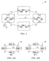
- FIGURE 1 there is shown a block diagram that illustrates the physical topology of an exemplary computer network 100.
- the computer network 100 includes bridges A, B, C and D (only four shown) that are interconnected to one another by links 102.
- Each bridge A, B, C and D includes one or more ports P1, P2 and P3 each of which is connected to a port on another bridge A, B, C or D via one of the links 102.
- the number of bridges A, B, C and D shown within computer network 100 has been selected for simplicity of illustration and that the number of bridges A, B, C and D and their configuration should not be a limitation on the present invention.
- the present invention also covers bridges when they are configured to form one or many MSTP regions.
- the computer network 100 includes a plurality of redundant communication paths. For example, there are at least three different communication paths from bridge B to bridge A including: path #1 from bridge B to bridge A; path #2 from bridge B to bridge C to bridge A; and path #3 from bridge B to bridge D to bridge C to bridge A.
- the existence of such redundant paths prevents portions of the computer network 100 from becoming isolated should any constituent link 102 or bridge A, B, C or D fail.
- Such redundancy also results in the creation of loops that are highly undesirable.
- bridge A, B, C and D execute the MSTP to reduce the physical topology of the computer network 100 to an active topology that is both loop-free ('tree') and fully-connected ('spanning').
- FIGURES 2A and 2B illustrate two exemplary MSTIs labeled MSTI 1 and MSTI 2 that are configured in a manner that eliminates loops in the computer network 100 while at the same time conserving simple and full connectivity within the computer network 100 between bridges A, B, C and D.
- the ports attached to the "dashed" links 102 in MSTI 1 and MSTI 2 are not forwarding data traffic.
- the "dashed" links 102 are not part of the active topology of either MSTI 1 or MSTI 2.
- the active topology of a MSTI is a topology that is made up of links 102 whose ports that are connected to them are forwarding data traffic.
- the "dashed" links 102 in MSTI 1 and MSTI 2 are not part of the active topology of MSTI 1 or MSTI 2 but might become part of the active topology of MSTI 1 or MSTI 2 if the ports connected to them are commanded by MSTP to start forwarding data traffic, e.g. if there is a failure in the computer network 100 (see FIGURE 6 ).
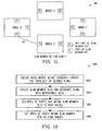
- FIGURES 3A and 3B illustrate two exemplary VLANS labeled VLAN 1 and VLAN 2 that can be created within the computer network 100.
- the data traffic assigned to VLAN 1 should not be forwarded between bridges A and B or between bridges A and C.
- the data traffic assigned to VLAN 2 should not be forwarded directly between bridges B and C.
- the "dashed" links 102 in VLAN 1 and VLAN 2 indicate an alternative link 102 that can be used in case of the failure of one of the other links 102 in VLAN 1 and VLAN 2.
- FIGURES 4A-4D there are shown various scenarios that can occur when VLAN 1 and VLAN 2 are mapped onto and associated with MSTI 1 and MSTI 2.
- VLAN 1 can be properly mapped onto and associated with MSTI 1 since the active topology of MSTI 1 covers the topology of VLAN 1 entirely.
- FIGURE 4B VLAN 2 should not be mapped onto nor associated with MSTI 1 since the active topology of MSTI 1 does not cover the topology of VLAN 2 entirely.
- data would be dropped between bridges A and B.
- VLAN 1 should not be mapped onto nor associated with MSTI 2 since the active topology of MSTI 2 does not cover the topology of VLAN 1 entirely.
- VLAN 1 was mapped onto or associated with MSTI 2 then data would be dropped between bridges B and C.
- FIGURE 4D VLAN 2 can be properly mapped onto and associated with MSTI 2 since the active topology of MSTI 2 covers the topology of VLAN 2 entirely.
- the "thick" links 102 in FIGURES 4A-4D indicate links 102 that are in the active topologies of MSTI 1 and MSTI 2 but are not in the topologies of VLAN 1 and VLAN 2.
- VLAN 1 should be mapped onto and associated with MSTI 1 and VLAN 2 should be mapped onto and associated with MSTI 2 (see FIGURES 4A and 4D ).
- This association leads to the definition of VLAN member sets on a per-VLAN basis with respect to individual MSTIs.
- Each VLAN member set includes all ports P1, P2 or P3 in bridges A, B, C or D to which data traffic destined to the members of a specific VLAN should be forwarded.
- FIGURES 5A and 5B To help describe the VLAN member sets in more detail reference is made to FIGURES 5A and 5B .
- FIGURE 5A there is a block diagram illustrating which of the ports P1, P2 or P3 in bridges A, B, C or D are part of the member set for VLAN 1.
- the ports P1, P2 or P3 in bridges A, B, C or D can be classified as follows:
- FIGURE 5B there is a block diagram illustrating which of the ports P1, P2 or P3 in bridges A, B, C or D are part of the member set for VLAN 2.
- the ports P1, P2 or P3 in bridges A, B, C or D can be classified as follows:
- the first feature of the present invention is performed. That is, the IPPCs of the "shaded" ports P1, P2 and P3 in bridges A, B, C and D and in the corresponding MSTI that are not part of the VLAN member set are set to a High IPPC (HiIPPC) value chosen in such a way that the corresponding ports are among the last ones to be commanded by MSTP to start forwarding data traffic if needed after a failure in the computer network.
- HiIPPC High IPPC
- the IPPC of those ports P1, P2 and P3 can be set to a value higher than any of the values used for the IPPCs of ports that are part of the VLAN member set, ideally between the highest value allowed by their encoding and the highest IEEE standard recommended value (e.g., see IEEE Std 802.1sTM-2002 or IEEE Std 802.1QTM-2003), regardless of the type of links 102 that are connected to those ports P1, P2 and P3.
- IEEE Std 802.1sTM-2002 or IEEE Std 802.1QTM-2003 regardless of the type of links 102 that are connected to those ports P1, P2 and P3.
- the IPPCs of the ports P1, P2 and P3 in bridges A, B, C and D and in the corresponding MSTI that are part of the VLAN member set are set to a Lower IPPC (LoIPPC) value chosen sufficiently lower than the HiIPPC value in such a way that the corresponding ports are among the first ones to be commanded by MSTP to start forwarding data traffic if needed after failure in the computer network.
- the IPPC of those ports P1, P2 and P3 can be set to IEEE standard recommended values based on the link speed of the links 102 that are connected to those ports P1, P2 and P3 (e.g., see IEEE Std 802.1sTM-2002 and IEEE Std 802.1QTM-2003).
- a CLI 104 is a device connected to or part of a bridge that allows for human interaction with the bridge. Such interaction can be either direct or indirect, i.e.
- the human operator can provide input to or receive output from the bridge and have this input/output generated live or retrieved from or dumped to one or more files, e.g. for later review or automatic processing.
- the CLI 104 can be used to operate one or many bridges. It should be appreciated that only one CLI 104 appears on Figure 1 although more than one may be used on one or many bridges.
- the application of the first feature of the present invention results in the MSTP reestablishing connectivity in a MSTI experiencing a failure by preferably activating links 102 whose activation ensures that the connectivity within a VLAN mapped onto and associated with that MSTI is not lost.
- this technique takes into account all physical links 102 as required by IEEE Std 802.1sTM-2002 or any other equivalent standard such as IEEE Std 802.1QTM-2003 and makes sure that links 102 not used by a VLAN are so expensive that they are only used as a last resort which usually means that the desired VLAN topology can no longer be achieved, as more thoroughly explained next.
- FIGURE 6 shows a scenario where the connectivity within VLAN 1 is maintained when the link 102 between bridges B and C fails and then the link 102 between bridges B and D is activated.
- FIGURE 7 shows another scenario where the connectivity within VLAN 1 is not maintained when two link 102 failures in that VLAN 1 cause MSTP to reestablish connectivity in MSTI 1 by activating two high-cost "thick" links 102 outside VLAN 1. In this scenario, the connectivity within VLAN 1 is lost although this is expected behavior, as VLAN 1 does not span the entire physical topology.
- the second feature is to be generally used in the situation when, after trying to map a VLAN onto the active topologies of all existing MSTIs, the active topology of any MSTI does not cover that VLAN entirely, i.e. when there is no match between that VLAN and any MSTI.
- a centralized network management system (for example based on the Simple Network Management Protocol - SNMP) can be used to create and configure in a fully-automatic fashion, a new MSTI that matches a previously un-matched VLAN by configuring all of the bridges participating in the physical topology, based on existing information.
- a semi-automatic process can be used to implement the second feature of the present invention where the network administrator is assisted and guided in the creation and configuration of a new MSTI using for example the CLI 104.
- the values of the IPPCs of the ports P1, P2 and P3 in the bridges are chosen to avoid dropping the data traffic of a VLAN as described above with respect to the first feature of the present invention.
- the second feature of the present invention can be used in any situation to create and configure MSTIs in addition to being used to create and configure MSTIs when a VLAN does not match existing MSTIs.
- FIGURE 8 illustrates an exemplary VLAN labeled as VLAN 3 that could be created and configured by a network administrator in computer network 100 leading to the creation of an appropriate VLAN member set.
- This VLAN member set includes all ports P1, P2 or P3 in bridges A, B, C or D to which data traffic destined to the members of VLAN 3 should be forwarded.
- FIGURES 2A and 2B it can be readily seen that VLAN 3 should not be mapped onto and associated with the active topologies of either MSTI 1 or MSTI 2 because the data traffic of VLAN 3 between bridge B and D would be dropped.
- FIGURE 9 illustrates one exemplary MSTI labeled as MSTI 3 that can be created whose active topology covers the topology of VLAN 3 entirely.
- VLAN 3 should be mapped onto and associated with MSTI 3.
- VLAN 1 and VLAN 2 should not be mapped onto nor associated with MSTI 3.
- FIGURE 11 there is a block diagram illustrating which of the ports P1, P2 or P3 in bridges A, B, C or D are part of the member set for VLAN 3.
- the ports P1, P2 or P3 in bridges A, B, C or D can be classified as follows:
- the first feature of the present invention is performed. That is, the IPPCs of the "shaded" ports P1, P2 and P3 in bridges A, B, C and D and in MSTI 3 that are not part of the VLAN member set are set to a HiIPPC value. And, the IPPCs of the "non-shaded" ports P1, P2 and P3 in bridges A, B, C and D and in MSTI 3 that are part of the VLAN member set are set to a LoIPPC value.
- the setting of the IPPCs of all the ports P1, P2 and P3 can be fully-automatic or semi-automatic. In the latter case, the network administrator can be assisted and guided to select the values of the IPPCs using for example the CLI 104.
- the application of the first feature of the present invention results in MSTP reestablishing connectivity in a MSTI experiencing a failure by preferably activating links 102 whose activation ensures that the connectivity within a VLAN mapped onto and associated with that MSTI is not lost.
- this technique takes into account all physical links 102 as required by the IEEE Std 802.1sTM-2002 or any other equivalent standard such as IEEE Std 802.1QTM-2003 and makes sure that links 102 not used by VLAN 3 are so expensive that they are only used as a last resort which usually means that the desired VLAN topology can no longer be achieved.
- FIGURE 12 there is shown a flowchart of the basic steps of a preferred method 1200 for obtaining the best connectivity achievable within VLANs when these VLANs are mapped onto a computer network 100 managed by the MSTP in accordance with the two features of the present invention.
- the MSTP engines 106 within bridges A, B, C and D are used to create and configure MSTIs (see FIGURES 2A and 2B ).
- the active topology of those MSTIs can be obtained by letting MSTP configure as many MSTIs as necessary or by having the network administrator influence the creation and configuration of as many appropriate MSTIs as necessary.
- the active topology of the created MSTIs might or might not cover the topology of the VLANs that are planned to be used by the network administrator.
- the network administrator can at step 1202 or at any point in method 1200 and in accordance with the second feature of the present invention create and configure MSTIs (see FIGURE 9 ) whose active topology covers the topology of the VLANs that are planned to be used (see FIGURES 3A and 3B ).
- the processing units 108 in bridges A, B, C and D are used to create VLAN member sets for each VLAN and to both map onto and associate each VLAN with the appropriate MSTI (see FIGURES 5A, 5B ).
- the processing units 108 in bridges A, B, C and D are used to set the IPPC of any port P1, P2 and P3 of any bridge A, B, C and D within one MSTI to a HiIPPC value if that port is not part of the VLAN member set (see shaded ports in FIGURES 5A and 5B ).
- the processing units 108 in bridges A, B, C and D are used to set the IPPC of any port P1, P2 and P3 of any bridge A, B, C and D within one MSTI to a LoIPPC value if that port is part of the VLAN member set (see non-shaded ports in FIGURES 5A and 5B ).
- the computer network 100 can then be operated while the first feature of the present invention helps to maintain the best connectivity within the VLAN.
- the present invention provides a method for fully- or semi-automatically configuring IPPCs of ports in the bridges of a computer network and in fully- or semi-automatically creating as many new MSTIs as necessary to ensure proper VLAN connectivity.
- the method does not "prune” any MSTI like in the prior art, which maintains compliancy with IEEE Std 802.1sTM-2002 or any other equivalent standard such as IEEE Std 802.1QTM-2003.
- the present invention works optimally when only one VLAN is mapped onto one MSTI or, pending modification of its textual content, when more than one VLAN but VLANs with a common topology (i.e. their topologies have all their links 102 in common) are mapped onto one MSTI.
- the present invention can be extended to accommodate the case where more than one VLAN are mapped onto one MSTI and those VLANs do not share a common topology (i.e. their topologies have zero or more but not all of their links 102 in common).
- the solution might not be as optimal as in the previous case, i.e. the best connectivity might not be achieved all the time.
- IPPCs are defined on a per-port basis but not both on a per-port and per-VLAN basis in a MSTI.
- the IPPCs of the ports that do not belong to any VLAN member set should be set to a HiIPPC value V1.
- ports that belong to one or many VLAN member sets but not to some other VLAN member sets should be set to high values lower than V1. The choice of those high values would be at the discretion of the network administrator so as to favor those VLANs whose connectivity integrity matters most.
- the IPPCs of the ports connected to links 102 common to all VLANs might be set to a LoIPPC value, lower than the high values.
- the second feature of the invention could be customized so as to provide the network administrator with what-if scenarios showing the consequences in terms of connectivity of setting the IPPCs of ports within a MSTI to chosen values.
- the second feature of the present invention could also integrate algorithms (e.g. computing many of these what-if scenarios automatically) whose goal would be to provide the network administrator with one or many sets of IPPCs. Each set would contain enough information to allow for fully- or semi-automatically setting the IPPC of each port in a MSTI so as to ensure that the highest connectivity is achieved within each of the VLANs mapped onto that MSTI.
- the IPPC of a port is defined on a per-MSTI basis.
- the Central and Internal Spanning Tree (CIST) defined as part of MSTP includes one or many internal parts, each of which when taken individually within a MSTP region is an MSTI, MSTI number zero.
- the IPPCs of the ports within this MSTI number zero can also be set as described in the first feature of the present invention.
- the setting of the IPPCs as described in the first feature of the present invention could be extended to accommodate not only a MSTI but any equivalent single spanning tree.
- a MSTI is a single spanning tree that, when taken together with other MSTIs that are also single spanning trees, forms a set of single spanning trees often referred to as a multiple spanning tree.
- Algorithms and protocols like the Spanning Tree algorithm and Protocol (STP) defined in IEEE Std 802.1DTM-1998 and the Rapid Spanning Tree algorithm and Protocol (RSTP) defined in IEEE Std 802.1wTM-2001 can also be used to create, configure and maintain one or many single spanning trees.
- STP Spanning Tree algorithm and Protocol
- RSTP Rapid Spanning Tree algorithm and Protocol
- Those algorithms and protocols like the MSTP all rely on the spanning tree algorithm invented by Radia Perlman and described in her book entitled "Interconnections Second Edition Bridges, Routers, Switches, and Internetworking Protocols" by Addison-Wesley Publishing Company, Inc..
- IPPCs Port Path Costs
Landscapes
- Engineering & Computer Science (AREA)
- Computer Networks & Wireless Communication (AREA)
- Signal Processing (AREA)
- Computer Security & Cryptography (AREA)
- Small-Scale Networks (AREA)
- Data Exchanges In Wide-Area Networks (AREA)
- Mobile Radio Communication Systems (AREA)
Claims (18)
- Ein Verfahren zum Anwenden in einer Brücke (A, B. C, D) mit einer Vielzahl von Ports, welche über Links (102) an andere Ports und Brücken in einem in eine Vielzahl von virtuellen lokalen Netzwerken, VLAN, aufgeteilten Computer-Netzwerk (100) angeschlossen sind, wobei eine Vielzahl von Multiple-Spanning-Tree-Instanzen, MSTI, eingerichtet (1202) und konfiguriert wird, und wobei jedes VLAN mit einer entsprechenden MSTI assoziiert ist, wobei das Verfahren durch die folgenden Schritte gekennzeichnet ist: Einrichten von (1204) VLAN-Mitgliedergruppen, wobei jede VLAN-Mitgliedergruppe alle Ports (P1, P2, P3) in Brücken (A, B, C, D), an welche ein für die Mitglieder eines spezifischen VLANs bestimmter Datenverkehr weitergeleitet werden soll, umfasst; Einstellen (1206) eines jeden beliebigen der Ports in der besagten Brücke auf einen hohen internen Portpfadkostenwert, IPPC, wenn dieser Port nicht einer Mitgliedergruppe eines VLANs, welche auf eine MSTI gemappt und damit assoziiert ist, angehört; und Einstellen (1208) eines jeden beliebigen der Ports in der besagten Brücke auf einen niedrigeren IPPC-Wert, wenn dieser Port der Mitgliedergruppe eines VLANs, welche auf eine MSTI gemappt und damit assoziiert ist, angehört.
- Das Verfahren nach Anspruch 1, wobei die Brücke auf Schicht 2 des Referenzmodells für die Kommunikation offener Systeme arbeitet.
- Das Verfahren nach Anspruch 1, wobei die besagten Einstellschritte voll- oder halbautomatisch erfolgen.
- Das Verfahren nach Anspruch 1, wobei:der besagte hohe IPPC-Einstellwert hoch genug gewählt wird, so dass die entsprechenden Ports unter den letzten Ports sind, welche von einem Multiple-Spanning-Tree-Protokoll, MSTP, gesteuert werden, um bei Bedarf, zum Beispiel nach einer Störung im Computer-Netzwerk, die Weiterleitung des Datenverkehrs zu beginnen; und dass der besagte niedrigere IPPC-Einstellwert niedriger genug als der hohe IPPC-gewählt wird, so dass die entsprechenden Ports unter den ersten Ports sind, welche vom MSTP gesteuert werden, um bei Bedarf, zum Beispiel nach einer Störung im Computer-Netzwerk.
- Das Verfahren nach Anspruch 4, wobei:der besagte hohe IPPC-Wert ein Wert sein kann, welcher höher ist als irgend einer der Werte, welche für die IPPCs von Ports, die Teil einer VLAN-Mitgliedergruppe sind, benutzt werden, idealerweise zwischen dem von deren Codierung zugelassenen höchsten Wert und dem höchsten empfohlenen IEEE-Standardwert, ungeachtet des Typs von Links, welche an diese Ports angeschlossen sind; undder besagte niedrigere IPPC-Wert ein vom IEEE-Standard empfohlener Wert, basierend auf der Geschwindigkeit der Links, welche an diese Ports angeschlossen sind, sein kann.
- Das Verfahren nach Anspruch 1, wobei die MSTI unter Verwendung eines Multiple Spanning Tree Protocol, MSTP-Automaten eingerichtet und konfiguriert wird.
- Eine Brücke (A, B, C, D) mit einer Vielzahl von Ports, welche über Links (102) an andere Ports und Brücken in einem in eine Vielzahl von virtuellen lokalen Netzwerken, VLAN, aufgeteilten Computer-Netzwerk (100) angeschlossen sind, wobei die besagte Brücke einen Multlple-Spanning-Tree-Protokoll, MSTP-Automaten, welcher dazu ausgelegt ist, eine Vielzahl von Multiple-Spanning-Tree-Instanzen, MSTI, einzurichten (1202) und zu konfigurieren, und eine Verarbeitungseinheit, welche dazu ausgelegt ist, jedes VLAN mit einer entsprechenden MSTI zu assoziierten, umfasst, wobei die besagte Brücke dadurch gekennzeichnet ist, dass die besagte Verarbeitungseinheit dazu ausgelegt ist, VLAN-Mitgliedergruppen einzurichten (102a), wobei jede VLAN-Mitgliedergruppe alle Ports (P1, P2, P3) in Brücken (A, B, C, D), an welche ein für die Mitglieder eines spezifischen VLANs bestimmter Datenverkehr weitergeleitet werden soll, umfasst; dass die besagte Verarbeitungseinheit dazu ausgelegt ist, einen internen Portpfadkostenwert, IPPC, eines jeden beliebigen der Ports in der Brücke innerhalb einer MSTI auf einen hohen IPPC-Wert einzustellen (1206), wenn dieser Port nicht einer VLAN-Mitgliedergruppe angehört; und dass die besagte Verarbeitungseinheit dazu ausgelegt ist, den IPPC-Wert eines jeden beliebigen der Ports der besagten Brücke innerhalb der einen MSTI auf einen niedrigeren IPPC-Wert einzustellen (1208), wenn dieser Port der VLAN-Mitgliedergruppe angehört.
- Die Brücke nach Anspruch 7, wobei die besagte Brücke dazu ausgelegt ist, auf Schicht 2 des Referenzmodells für die Kommunikation offener Systeme zu arbeiten.
- Die Brücke nach Anspruch 7, wobei:der besagte hohe IPPC-Einstellwert hoch genug gewählt wird, so dass die entsprechenden Ports unter den letzten Ports sind, welche von einem Multiple-Spanning-Tree-Protokoll, MSTP, gesteuert werden, um bei Bedarf, zum Beispiel nach einer Störung im Computer-Netzwerk, die Weiterleitung des Datenverkehrs zu beginnen; und dass der besagte niedrigere IPPC-Einstellwert niedriger genug als der hohe IPPC-Wert gewählt wird, so dass die entsprechenden Ports unter den ersten Ports sind, welche vom MSTP gesteuert werden, um bei Bedarf, zum Beispiel nach einer Störung im Computer-Netzwerk, die Weiterleitung des Datenverkehrs zu beginnen.
- Die Brücke nach Anspruch 9, wobei:der besagte hohe IPPC-Wert ein Wert sein kann, welcher höher ist als irgend einer der Werte, welche für die IPPCs von Ports, die Teil einer VLAN-Mitgliedergruppe sind, benutzt werden, idealerweise zwischen dem von deren Codierung zugelassenen höchsten Wert und dem höchsten empfohlenen IEEE-Standardwert, ungeachtet des Typs von Links, welche an diese Ports angeschlossen sind; undder besagte niedrigere IPPC-Wert ein vom IEEE-Standard empfohlener Wert, basierend auf der Geschwindigkeit der Links, welche an diese Ports angeschlossen sind, sein kann.
- Die Brücke nach Anspruch 7, wobei die Brücke Mittel umfasst, welche dazu ausgelegt sind, eine oder mehrere MSTIs sowie ein oder mehrere VLANs und deren Assoziierung zu diesen MSTIs einzurichten, zu warten und zu entfernen.
- Ein Computer-Netzwerk (100), umfassend:Eine Brücke (A, B, C, D) mit einer Vielzahl von Ports, welche über Links (102) an andere Ports und Brücken angeschlossen sind, wobei das besagte Computer-Netzwerk Mittel umfasst, welche dazu ausgelegt sind, eine Vielzahl von Multiple-Spannirig-Tree-Instanzen, MSTI, deren Topologie die Topologie von innerhalb des Computer-Netzwerks benutzten virtuellen lokalen Netzwerken, VLAN, abdeckt, einzurichten (1202) und zu konfigurieren und jedes VLAN mit einer entsprechenden MSTI zu assoziierten, wobei das besagte Computer-Netzwerk gekennzeichnet ist durch:Mittel, welche dazu ausgelegt sind, VLAN-Mitgliedergruppen einzurichten (1204), wobei jede VLAN-Mitgliedergruppe alle Ports (P1, P2, P3) in Brücken (A, B, C. D), an welche ein für die Mitglieder eines spezifischen VLANs bestimmter Datenverkehr weitergeleitet werden soll;Mittel, welche dazu ausgelegt sind, einen internen Portpfadkostenwert, IPPC, eines jeden beliebigen der Ports einer jeden beliebigen Brücke innerhalb der einen MSTI auf einen hohen IPPC-Wert einzustellen (1206), wenn ein beliebiger Port einer beliebigen Brücke innerhalb der einen MSTI nicht einer VLAN-Mitgliedergruppe angehört; undMittel, welche dazu ausgelegt sind, den IPPC-Wert eines jeden beliebigen Ports einer jeden beliebigen Brücke innerhalb der einen MSTI auf einen niedrigeren IPPC-Wert einzustellen (1208), wenn dieser Port der VLAN-Mitgliedergruppe angehört.
- Das Computer-Netzwerk nach Anspruch 12, wobei jede MSTI unter Verwerdung eines Multiple-Spanning-Tree-Protokoll, MSTP-Automaten eingerichtet und konfiguriert wird.
- Das Computer-Netzwerk nach Anspruch 12, wobei die besagten Schritte des Einrichtens von MSTIs und von VLAN-Mitgliedergruppen und die besagten Einstellschritte für eine jede der MSTIs wiederholt werden.
- Das Computer-Netzwerk nach Anspruch 12, wobei die besagte VLAN-Mitgliedergruppe die Ports in einer jeden der Brücken innerhalb einer der MSTIs, an welche ein für die Mitglieder eines spezifischen VLANs bestimmter Datenverkehr weitergeleitet werden soll, anzeigt.
- Das Computer-Netzwerk nach Anspruch 12, wobei jede Brücke dazu ausgelegt ist, auf Schicht 2 des Referenzmodells für die Kommunikation offener Systeme zu arbeiten.
- Das Computer-Netzwerk nach Anspruch 12, wobei:der besagte hohe IPPC-Einstellwert hoch genug gewählt wird, so dass die entsprechenden Ports unter den letzten Ports sind, welche von einem Multiple-Spanning-Tree-Protokoll, MSTP, gesteuert werden, um bei Bedarf, zum Beispiel nach einer Störung im Computer-Netzwerk, die Weiterleitung des Datenverkehrs zu beginnen; und dass der besagte niedrigere IPPC-Einstellwert niedriger genug als der hohe IPPC-gewählt wird, so dass die entsprechenden Ports unter den ersten Ports sind, welche vom MSTP gesteuert werden, um bei Bedarf, zum Beispiel nach einer Störung im Computer-Netzwerk.
- Das Computer-Netzwerk nach Anspruch 17, wobei:der besagte hohe IPPC-Wert ein Wert sein kann, welcher höher ist als irgend einer der Werte, welche für die IPPCs von Ports, die Teil einer VLAN-Mitgliedergruppe sind, benutzt werden, idealerweise zwischen dem von deren Codierung zugelassenen höchsten Wert und dem höchsten empfohlenen IEEE-Standardwert, ungeachtet des Typs von Links, welche an diese Ports angeschlossen sind: undder besagte niedrigere IPPC-Wert ein vom IEEE-Standard empfohlener Wert, basierend auf der Geschwindigkeit der Links, welche an diese Ports angeschlossen sind, sein kann.
Applications Claiming Priority (2)
| Application Number | Priority Date | Filing Date | Title |
|---|---|---|---|
| US10/741,687 US7565435B2 (en) | 2003-12-20 | 2003-12-20 | Method for obtaining the best connectivity achievable within virtual local area networks |
| US741687 | 2003-12-20 |
Publications (2)
| Publication Number | Publication Date |
|---|---|
| EP1545068A1 EP1545068A1 (de) | 2005-06-22 |
| EP1545068B1 true EP1545068B1 (de) | 2010-02-10 |
Family
ID=34523232
Family Applications (1)
| Application Number | Title | Priority Date | Filing Date |
|---|---|---|---|
| EP04029618A Expired - Lifetime EP1545068B1 (de) | 2003-12-20 | 2004-12-15 | Verfahren zur Optimierung der Verbindungsmöglichkeit in virtuellen lokalen Netzen (VLAN) |
Country Status (5)
| Country | Link |
|---|---|
| US (1) | US7565435B2 (de) |
| EP (1) | EP1545068B1 (de) |
| CN (1) | CN1630261A (de) |
| AT (1) | ATE457573T1 (de) |
| DE (1) | DE602004025447D1 (de) |
Families Citing this family (17)
| Publication number | Priority date | Publication date | Assignee | Title |
|---|---|---|---|---|
| US20060268748A1 (en) * | 2005-05-27 | 2006-11-30 | Laurence Rose | Facilitating Computation of Role and State Information for Multiple Spanning Tree Instances |
| US20070002770A1 (en) * | 2005-06-30 | 2007-01-04 | Lucent Technologies Inc. | Mechanism to load balance traffic in an ethernet network |
| CN100454896C (zh) * | 2005-07-15 | 2009-01-21 | 华为技术有限公司 | 一种虚拟交换系统中故障恢复的方法 |
| US7760738B1 (en) * | 2005-07-28 | 2010-07-20 | Verizon Services Corp. | Admission control for services |
| US7646733B2 (en) * | 2005-09-16 | 2010-01-12 | Cisco Technology, Inc. | System and method for generating symmetrical spanning trees |
| ATE413746T1 (de) * | 2005-09-23 | 2008-11-15 | Nokia Siemens Networks Gmbh | Verfahren zur erweiterung eines netzes |
| US7580372B2 (en) | 2005-12-15 | 2009-08-25 | Alcatel Lucent | System and method for implementing multiple spanning tree protocol automatic 802.1Q trunking |
| US8565123B2 (en) * | 2006-05-03 | 2013-10-22 | Cisco Technology, Inc. | System and method for running a multiple spanning tree protocol with a very large number of domains |
| CN101507194B (zh) * | 2006-06-27 | 2012-08-15 | 艾利森电话股份有限公司 | 桥接的以太网中的强制介质访问控制(mac)学习 |
| CN101106516A (zh) * | 2006-07-14 | 2008-01-16 | 华为技术有限公司 | 一种避免弹性分组相交环广播风暴的相交节点及方法 |
| EP2149229B1 (de) * | 2007-04-20 | 2010-11-17 | Telefonaktiebolaget LM Ericsson (publ) | Verfahren und vorrichtung zur planung der dienstmittel (qos) für ein auf ethernet basierendes netzwerk |
| JP5441908B2 (ja) * | 2007-10-12 | 2014-03-12 | ノーテル・ネットワークス・リミテッド | マルチポイント及び同根マルチポイントの保護切り換え |
| US7835306B2 (en) * | 2008-01-23 | 2010-11-16 | Cisco Technology, Inc. | Translating MST instances between ports of a bridge in a computer network |
| JP5157533B2 (ja) * | 2008-03-05 | 2013-03-06 | 富士通株式会社 | ネットワーク管理装置、ネットワーク管理方法およびネットワーク管理プログラム |
| US7944860B2 (en) * | 2009-06-04 | 2011-05-17 | Cisco Technology, Inc. | Preventing loss of network traffic due to inconsistent configurations within the network |
| US20140293827A1 (en) * | 2013-03-28 | 2014-10-02 | Sandeep Kumar | Method And Apparatus For Peer Node Synchronization |
| CN105933222B (zh) * | 2016-04-12 | 2019-01-15 | 烽火通信科技股份有限公司 | 一种ce双归接入pe组网中基于mstp的防环方法 |
Family Cites Families (10)
| Publication number | Priority date | Publication date | Assignee | Title |
|---|---|---|---|---|
| US5394402A (en) | 1993-06-17 | 1995-02-28 | Ascom Timeplex Trading Ag | Hub for segmented virtual local area network with shared media access |
| US5878232A (en) | 1996-12-27 | 1999-03-02 | Compaq Computer Corporation | Dynamic reconfiguration of network device's virtual LANs using the root identifiers and root ports determined by a spanning tree procedure |
| US6032194A (en) | 1997-12-24 | 2000-02-29 | Cisco Technology, Inc. | Method and apparatus for rapidly reconfiguring computer networks |
| US6515969B1 (en) | 1999-03-01 | 2003-02-04 | Cisco Technology, Inc. | Virtual local area network membership registration protocol for multiple spanning tree network environments |
| JP4651244B2 (ja) * | 2001-09-17 | 2011-03-16 | 富士通株式会社 | スイッチ及びブリッジド・ネットワーク |
| US20030169694A1 (en) * | 2002-03-07 | 2003-09-11 | Seaman Michael John | Use of alternate ports in spanning tree configured bridged virtual local area networks |
| US7292581B2 (en) * | 2002-10-24 | 2007-11-06 | Cisco Technology, Inc. | Large-scale layer 2 metropolitan area network |
| US7627654B2 (en) * | 2003-06-09 | 2009-12-01 | Foundry Networks, Inc. | System and method for multiple spanning tree protocol domains in a virtual local area network |
| US7697432B2 (en) * | 2003-06-27 | 2010-04-13 | Broadcom Corporation | Equal and weighted cost multipath load balancing in a network device |
| US7324461B2 (en) * | 2003-08-26 | 2008-01-29 | Alcatel Lucent | Selective transmission rate limiter for rapid spanning tree protocol |
-
2003
- 2003-12-20 US US10/741,687 patent/US7565435B2/en active Active
-
2004
- 2004-12-15 AT AT04029618T patent/ATE457573T1/de not_active IP Right Cessation
- 2004-12-15 EP EP04029618A patent/EP1545068B1/de not_active Expired - Lifetime
- 2004-12-15 DE DE602004025447T patent/DE602004025447D1/de not_active Expired - Lifetime
- 2004-12-17 CN CNA2004101013490A patent/CN1630261A/zh active Pending
Also Published As
| Publication number | Publication date |
|---|---|
| EP1545068A1 (de) | 2005-06-22 |
| US20050149625A1 (en) | 2005-07-07 |
| ATE457573T1 (de) | 2010-02-15 |
| DE602004025447D1 (de) | 2010-03-25 |
| US7565435B2 (en) | 2009-07-21 |
| CN1630261A (zh) | 2005-06-22 |
Similar Documents
| Publication | Publication Date | Title |
|---|---|---|
| EP1545068B1 (de) | Verfahren zur Optimierung der Verbindungsmöglichkeit in virtuellen lokalen Netzen (VLAN) | |
| US7292581B2 (en) | Large-scale layer 2 metropolitan area network | |
| US7835306B2 (en) | Translating MST instances between ports of a bridge in a computer network | |
| EP1142212B1 (de) | Virtuelle lokale netze mit prioritätsregeln | |
| US7177946B1 (en) | Optimal sync for rapid spanning tree protocol | |
| US6813250B1 (en) | Shared spanning tree protocol | |
| EP1048147B1 (de) | Virtuelles lokales netz mit mehrfachsendeschutz | |
| US6445715B1 (en) | Dynamic trunk protocol | |
| EP1469639B1 (de) | Verfahren, Softwareprodukt, Speichermedium und Ethernetswitch zur Verbesserung des STP Protokolls in VLAN Ethernet Netzwerken | |
| US20110134923A1 (en) | Intelligent Adjunct Network Device | |
| US20100309821A1 (en) | Method and network for combined protection of ethernet traffic | |
| US7502376B2 (en) | Layer-2 network with virtual private LAN service | |
| US7280488B2 (en) | Communication device, network system using same, and method of constructing spanning tree | |
| AU750300B2 (en) | Virtual local area networks with trunk stations | |
| AU737029B2 (en) | Privileged virtual local area networks | |
| US20030202463A1 (en) | Method for establishing a loop-free path for transfer of data packets within a circular network | |
| US7660271B2 (en) | Spanning tree BPDU processing method and system facilitating integration of different native VLAN configurations | |
| CN112866143A (zh) | 一种实现802.1cb协议的装置及芯片 | |
| KR101767439B1 (ko) | 소프트웨어 정의 네트워크에서 패킷의 경로를 설정하는 방법, 장치 및 컴퓨터 프로그램 | |
| EP1727318B1 (de) | Vereinfachte Berechnung der Rollen- und Zustandsinformation für Multiple Spanning Tree Instanzen | |
| AU779346B2 (en) | Virtual local area networks with trunk stations |
Legal Events
| Date | Code | Title | Description |
|---|---|---|---|
| PUAI | Public reference made under article 153(3) epc to a published international application that has entered the european phase |
Free format text: ORIGINAL CODE: 0009012 |
|
| AK | Designated contracting states |
Kind code of ref document: A1 Designated state(s): AT BE BG CH CY CZ DE DK EE ES FI FR GB GR HU IE IS IT LI LT LU MC NL PL PT RO SE SI SK TR |
|
| AX | Request for extension of the european patent |
Extension state: AL BA HR LV MK YU |
|
| 17P | Request for examination filed |
Effective date: 20051220 |
|
| AKX | Designation fees paid |
Designated state(s): AT BE BG CH CY CZ DE DK EE ES FI FR GB GR HU IE IS IT LI LT LU MC NL PL PT RO SE SI SK TR |
|
| 17Q | First examination report despatched |
Effective date: 20060113 |
|
| RAP1 | Party data changed (applicant data changed or rights of an application transferred) |
Owner name: ALCATEL LUCENT |
|
| GRAP | Despatch of communication of intention to grant a patent |
Free format text: ORIGINAL CODE: EPIDOSNIGR1 |
|
| GRAC | Information related to communication of intention to grant a patent modified |
Free format text: ORIGINAL CODE: EPIDOSCIGR1 |
|
| GRAS | Grant fee paid |
Free format text: ORIGINAL CODE: EPIDOSNIGR3 |
|
| GRAA | (expected) grant |
Free format text: ORIGINAL CODE: 0009210 |
|
| AK | Designated contracting states |
Kind code of ref document: B1 Designated state(s): AT BE BG CH CY CZ DE DK EE ES FI FR GB GR HU IE IS IT LI LT LU MC NL PL PT RO SE SI SK TR |
|
| REG | Reference to a national code |
Ref country code: GB Ref legal event code: FG4D |
|
| REG | Reference to a national code |
Ref country code: CH Ref legal event code: EP |
|
| REG | Reference to a national code |
Ref country code: IE Ref legal event code: FG4D |
|
| REF | Corresponds to: |
Ref document number: 602004025447 Country of ref document: DE Date of ref document: 20100325 Kind code of ref document: P |
|
| REG | Reference to a national code |
Ref country code: NL Ref legal event code: VDEP Effective date: 20100210 |
|
| LTIE | Lt: invalidation of european patent or patent extension |
Effective date: 20100210 |
|
| PG25 | Lapsed in a contracting state [announced via postgrant information from national office to epo] |
Ref country code: LT Free format text: LAPSE BECAUSE OF FAILURE TO SUBMIT A TRANSLATION OF THE DESCRIPTION OR TO PAY THE FEE WITHIN THE PRESCRIBED TIME-LIMIT Effective date: 20100210 Ref country code: ES Free format text: LAPSE BECAUSE OF FAILURE TO SUBMIT A TRANSLATION OF THE DESCRIPTION OR TO PAY THE FEE WITHIN THE PRESCRIBED TIME-LIMIT Effective date: 20100521 Ref country code: IS Free format text: LAPSE BECAUSE OF FAILURE TO SUBMIT A TRANSLATION OF THE DESCRIPTION OR TO PAY THE FEE WITHIN THE PRESCRIBED TIME-LIMIT Effective date: 20100610 Ref country code: PT Free format text: LAPSE BECAUSE OF FAILURE TO SUBMIT A TRANSLATION OF THE DESCRIPTION OR TO PAY THE FEE WITHIN THE PRESCRIBED TIME-LIMIT Effective date: 20100611 |
|
| PG25 | Lapsed in a contracting state [announced via postgrant information from national office to epo] |
Ref country code: PL Free format text: LAPSE BECAUSE OF FAILURE TO SUBMIT A TRANSLATION OF THE DESCRIPTION OR TO PAY THE FEE WITHIN THE PRESCRIBED TIME-LIMIT Effective date: 20100210 Ref country code: SI Free format text: LAPSE BECAUSE OF FAILURE TO SUBMIT A TRANSLATION OF THE DESCRIPTION OR TO PAY THE FEE WITHIN THE PRESCRIBED TIME-LIMIT Effective date: 20100210 Ref country code: FI Free format text: LAPSE BECAUSE OF FAILURE TO SUBMIT A TRANSLATION OF THE DESCRIPTION OR TO PAY THE FEE WITHIN THE PRESCRIBED TIME-LIMIT Effective date: 20100210 Ref country code: AT Free format text: LAPSE BECAUSE OF FAILURE TO SUBMIT A TRANSLATION OF THE DESCRIPTION OR TO PAY THE FEE WITHIN THE PRESCRIBED TIME-LIMIT Effective date: 20100210 |
|
| PG25 | Lapsed in a contracting state [announced via postgrant information from national office to epo] |
Ref country code: GR Free format text: LAPSE BECAUSE OF FAILURE TO SUBMIT A TRANSLATION OF THE DESCRIPTION OR TO PAY THE FEE WITHIN THE PRESCRIBED TIME-LIMIT Effective date: 20100511 Ref country code: EE Free format text: LAPSE BECAUSE OF FAILURE TO SUBMIT A TRANSLATION OF THE DESCRIPTION OR TO PAY THE FEE WITHIN THE PRESCRIBED TIME-LIMIT Effective date: 20100210 Ref country code: BE Free format text: LAPSE BECAUSE OF FAILURE TO SUBMIT A TRANSLATION OF THE DESCRIPTION OR TO PAY THE FEE WITHIN THE PRESCRIBED TIME-LIMIT Effective date: 20100210 Ref country code: CY Free format text: LAPSE BECAUSE OF FAILURE TO SUBMIT A TRANSLATION OF THE DESCRIPTION OR TO PAY THE FEE WITHIN THE PRESCRIBED TIME-LIMIT Effective date: 20100210 Ref country code: SE Free format text: LAPSE BECAUSE OF FAILURE TO SUBMIT A TRANSLATION OF THE DESCRIPTION OR TO PAY THE FEE WITHIN THE PRESCRIBED TIME-LIMIT Effective date: 20100210 Ref country code: RO Free format text: LAPSE BECAUSE OF FAILURE TO SUBMIT A TRANSLATION OF THE DESCRIPTION OR TO PAY THE FEE WITHIN THE PRESCRIBED TIME-LIMIT Effective date: 20100210 Ref country code: NL Free format text: LAPSE BECAUSE OF FAILURE TO SUBMIT A TRANSLATION OF THE DESCRIPTION OR TO PAY THE FEE WITHIN THE PRESCRIBED TIME-LIMIT Effective date: 20100210 |
|
| PG25 | Lapsed in a contracting state [announced via postgrant information from national office to epo] |
Ref country code: CZ Free format text: LAPSE BECAUSE OF FAILURE TO SUBMIT A TRANSLATION OF THE DESCRIPTION OR TO PAY THE FEE WITHIN THE PRESCRIBED TIME-LIMIT Effective date: 20100210 Ref country code: SK Free format text: LAPSE BECAUSE OF FAILURE TO SUBMIT A TRANSLATION OF THE DESCRIPTION OR TO PAY THE FEE WITHIN THE PRESCRIBED TIME-LIMIT Effective date: 20100210 Ref country code: BG Free format text: LAPSE BECAUSE OF FAILURE TO SUBMIT A TRANSLATION OF THE DESCRIPTION OR TO PAY THE FEE WITHIN THE PRESCRIBED TIME-LIMIT Effective date: 20100510 |
|
| PLBE | No opposition filed within time limit |
Free format text: ORIGINAL CODE: 0009261 |
|
| STAA | Information on the status of an ep patent application or granted ep patent |
Free format text: STATUS: NO OPPOSITION FILED WITHIN TIME LIMIT |
|
| 26N | No opposition filed |
Effective date: 20101111 |
|
| PG25 | Lapsed in a contracting state [announced via postgrant information from national office to epo] |
Ref country code: DK Free format text: LAPSE BECAUSE OF FAILURE TO SUBMIT A TRANSLATION OF THE DESCRIPTION OR TO PAY THE FEE WITHIN THE PRESCRIBED TIME-LIMIT Effective date: 20100210 |
|
| PG25 | Lapsed in a contracting state [announced via postgrant information from national office to epo] |
Ref country code: IT Free format text: LAPSE BECAUSE OF FAILURE TO SUBMIT A TRANSLATION OF THE DESCRIPTION OR TO PAY THE FEE WITHIN THE PRESCRIBED TIME-LIMIT Effective date: 20100210 |
|
| PG25 | Lapsed in a contracting state [announced via postgrant information from national office to epo] |
Ref country code: MC Free format text: LAPSE BECAUSE OF NON-PAYMENT OF DUE FEES Effective date: 20101231 |
|
| REG | Reference to a national code |
Ref country code: CH Ref legal event code: PL |
|
| PG25 | Lapsed in a contracting state [announced via postgrant information from national office to epo] |
Ref country code: LI Free format text: LAPSE BECAUSE OF NON-PAYMENT OF DUE FEES Effective date: 20101231 Ref country code: CH Free format text: LAPSE BECAUSE OF NON-PAYMENT OF DUE FEES Effective date: 20101231 Ref country code: IE Free format text: LAPSE BECAUSE OF NON-PAYMENT OF DUE FEES Effective date: 20101215 |
|
| PG25 | Lapsed in a contracting state [announced via postgrant information from national office to epo] |
Ref country code: LU Free format text: LAPSE BECAUSE OF NON-PAYMENT OF DUE FEES Effective date: 20101215 Ref country code: HU Free format text: LAPSE BECAUSE OF FAILURE TO SUBMIT A TRANSLATION OF THE DESCRIPTION OR TO PAY THE FEE WITHIN THE PRESCRIBED TIME-LIMIT Effective date: 20100811 |
|
| PG25 | Lapsed in a contracting state [announced via postgrant information from national office to epo] |
Ref country code: TR Free format text: LAPSE BECAUSE OF FAILURE TO SUBMIT A TRANSLATION OF THE DESCRIPTION OR TO PAY THE FEE WITHIN THE PRESCRIBED TIME-LIMIT Effective date: 20100210 |
|
| REG | Reference to a national code |
Ref country code: GB Ref legal event code: 732E Free format text: REGISTERED BETWEEN 20130926 AND 20131002 |
|
| REG | Reference to a national code |
Ref country code: FR Ref legal event code: CA Effective date: 20150521 |
|
| REG | Reference to a national code |
Ref country code: FR Ref legal event code: CA Effective date: 20150521 |
|
| REG | Reference to a national code |
Ref country code: FR Ref legal event code: PLFP Year of fee payment: 12 |
|
| REG | Reference to a national code |
Ref country code: FR Ref legal event code: PLFP Year of fee payment: 13 |
|
| PGFP | Annual fee paid to national office [announced via postgrant information from national office to epo] |
Ref country code: DE Payment date: 20161213 Year of fee payment: 13 Ref country code: GB Payment date: 20161222 Year of fee payment: 13 |
|
| PGFP | Annual fee paid to national office [announced via postgrant information from national office to epo] |
Ref country code: FR Payment date: 20161222 Year of fee payment: 13 |
|
| REG | Reference to a national code |
Ref country code: DE Ref legal event code: R119 Ref document number: 602004025447 Country of ref document: DE |
|
| GBPC | Gb: european patent ceased through non-payment of renewal fee |
Effective date: 20171215 |
|
| REG | Reference to a national code |
Ref country code: FR Ref legal event code: ST Effective date: 20180831 |
|
| PG25 | Lapsed in a contracting state [announced via postgrant information from national office to epo] |
Ref country code: FR Free format text: LAPSE BECAUSE OF NON-PAYMENT OF DUE FEES Effective date: 20180102 Ref country code: DE Free format text: LAPSE BECAUSE OF NON-PAYMENT OF DUE FEES Effective date: 20180703 |
|
| PG25 | Lapsed in a contracting state [announced via postgrant information from national office to epo] |
Ref country code: GB Free format text: LAPSE BECAUSE OF NON-PAYMENT OF DUE FEES Effective date: 20171215 |
|
| REG | Reference to a national code |
Ref country code: DE Ref legal event code: R082 Ref document number: 602004025447 Country of ref document: DE Representative=s name: BARKHOFF REIMANN VOSSIUS, DE Ref country code: DE Ref legal event code: R081 Ref document number: 602004025447 Country of ref document: DE Owner name: WSOU INVESTMENTS, LLC, LOS ANGELES, US Free format text: FORMER OWNER: ALCATEL LUCENT, PARIS, FR |
|
| REG | Reference to a national code |
Ref country code: GB Ref legal event code: 732E Free format text: REGISTERED BETWEEN 20201203 AND 20201209 |