EP1469639B1 - Verfahren, Softwareprodukt, Speichermedium und Ethernetswitch zur Verbesserung des STP Protokolls in VLAN Ethernet Netzwerken - Google Patents
Verfahren, Softwareprodukt, Speichermedium und Ethernetswitch zur Verbesserung des STP Protokolls in VLAN Ethernet Netzwerken Download PDFInfo
- Publication number
- EP1469639B1 EP1469639B1 EP04008847A EP04008847A EP1469639B1 EP 1469639 B1 EP1469639 B1 EP 1469639B1 EP 04008847 A EP04008847 A EP 04008847A EP 04008847 A EP04008847 A EP 04008847A EP 1469639 B1 EP1469639 B1 EP 1469639B1
- Authority
- EP
- European Patent Office
- Prior art keywords
- vlans
- topology
- port
- ports
- ethernet
- Prior art date
- Legal status (The legal status is an assumption and is not a legal conclusion. Google has not performed a legal analysis and makes no representation as to the accuracy of the status listed.)
- Expired - Lifetime
Links
- 238000000034 method Methods 0.000 title claims abstract description 51
- 238000013138 pruning Methods 0.000 claims abstract description 17
- 230000008859 change Effects 0.000 claims description 17
- 230000000977 initiatory effect Effects 0.000 claims 1
- 238000005457 optimization Methods 0.000 description 5
- 230000008569 process Effects 0.000 description 5
- 239000000835 fiber Substances 0.000 description 4
- 230000007704 transition Effects 0.000 description 4
- 238000004891 communication Methods 0.000 description 2
- 238000005516 engineering process Methods 0.000 description 2
- 238000001914 filtration Methods 0.000 description 2
- 230000000670 limiting effect Effects 0.000 description 2
- 230000004048 modification Effects 0.000 description 2
- 238000012986 modification Methods 0.000 description 2
- 230000002265 prevention Effects 0.000 description 2
- 230000001960 triggered effect Effects 0.000 description 2
- DWSYCUKCNSVBRA-UHFFFAOYSA-N 4-(5-methylsulfonyltetrazol-1-yl)phenol Chemical compound CS(=O)(=O)C1=NN=NN1C1=CC=C(C=C1)O DWSYCUKCNSVBRA-UHFFFAOYSA-N 0.000 description 1
- 101710167643 Serine/threonine protein phosphatase PstP Proteins 0.000 description 1
- 238000013459 approach Methods 0.000 description 1
- 230000005540 biological transmission Effects 0.000 description 1
- 238000010586 diagram Methods 0.000 description 1
- 230000008030 elimination Effects 0.000 description 1
- 238000003379 elimination reaction Methods 0.000 description 1
- 230000006870 function Effects 0.000 description 1
- 238000012545 processing Methods 0.000 description 1
- 230000011664 signaling Effects 0.000 description 1
- 238000000638 solvent extraction Methods 0.000 description 1
Images

Classifications
-
- H—ELECTRICITY
- H04—ELECTRIC COMMUNICATION TECHNIQUE
- H04L—TRANSMISSION OF DIGITAL INFORMATION, e.g. TELEGRAPHIC COMMUNICATION
- H04L45/00—Routing or path finding of packets in data switching networks
- H04L45/48—Routing tree calculation
-
- H—ELECTRICITY
- H04—ELECTRIC COMMUNICATION TECHNIQUE
- H04L—TRANSMISSION OF DIGITAL INFORMATION, e.g. TELEGRAPHIC COMMUNICATION
- H04L12/00—Data switching networks
- H04L12/28—Data switching networks characterised by path configuration, e.g. LAN [Local Area Networks] or WAN [Wide Area Networks]
- H04L12/46—Interconnection of networks
- H04L12/4604—LAN interconnection over a backbone network, e.g. Internet, Frame Relay
- H04L12/462—LAN interconnection over a bridge based backbone
-
- H—ELECTRICITY
- H04—ELECTRIC COMMUNICATION TECHNIQUE
- H04L—TRANSMISSION OF DIGITAL INFORMATION, e.g. TELEGRAPHIC COMMUNICATION
- H04L12/00—Data switching networks
- H04L12/28—Data switching networks characterised by path configuration, e.g. LAN [Local Area Networks] or WAN [Wide Area Networks]
- H04L12/46—Interconnection of networks
- H04L12/4641—Virtual LANs, VLANs, e.g. virtual private networks [VPN]
Definitions
- the technology relates to Ethernet networks supporting VLANs and utilizing a Spanning Tree Protocol in its various versions.
- Edge port - a port that is on the boundary of an STP/VLAN domain; the edge port is considered a permanently forwarding port.
- FDB - Filtering database - a standard database of MAC addresses in an Ethernet switching node, which is self-learned i.e., gradually formed during operation and based on registering source addresses from which data frames arrive to particular ports, thereby FDB "learns" the network for facilitating further switching decisions.
- PDU- Protocol Data Unit
- Ethernet switches nodes
- LAN Local Area Networks
- LAN may also comprise a number of Ethernet switches, where some support terminal/access ports (i.e. those directly connected to a LAN end-station or to those on the boundary of one STP domain to another).
- VLANs Virtual Local Area Networks
- a number of VLANs are usually defined in the network.
- VLANs may overlap one another, and normally, each particular VLAN must span each Ethernet switch that may be encountered in a path from one terminal to another, in any possible topology that may be imposed by the STP. Such a configuration of VLANs will be further called initial VLANs configuration. In many cases it can be that the initial configuration requires that all VLANs are provisioned on all ports throughout the network, that are not edge ports. VLANs can be configured on the Ethernet network by GVRP or a management interface such as SNMP.
- US patent 6,515,969 relates to a method and apparatus for disseminating Virtual Local Area Network (VLAN) membership information across computer networks defining multiple spanning trees.
- An intermediate network device includes a plurality of ports and a plurality of spanning tree engines each associated with one or more VLAN designations defined within the network. The spanning tree engines transition the ports among a plurality of port states, including a forwarding state and a blocked state.
- a separate Generic Attribute Registration Protocol (GARP) participant is also established and each GARP participant includes a multiple spanning tree (MST) GARP VLAN Registration Protocol (MST-GVRP) application component and an associated GARP Information Declaration (GID) component.
- MST multiple spanning tree
- MST-GVRP GARP VLAN Registration Protocol
- GID GARP Information Declaration
- the MST-GVRP application components cooperate to define a plurality of GARP Information Propagation (GIP) contexts each of which is associated with a spanning tree engine and thus its one or more VLAN designations.
- GIP GARP Information Propagation
- protocol for Ethernet networks supporting VLANs requires that the data frame carry indication of a specific VLAN to which both the source and the destination node(s) belongs.
- Ethernet switches passing therethrough a data packet which is not addressed to a known MAC address but carries indication of a specific VLAN, performs "flooding" of all its output ports assigned to that VLAN.
- all the relevant neighboring nodes are enabled to continue checking and forwarding that packet for the specified VLAN and, if indicated and known within the switch, to the specified destination MAC address.
- any Ethernet switch supports the Filtering Database (FDB) which is gradually formed by recording the source address indicated in a data packet (i.e. Ethernet frame) when the frame is received by one of the ports.
- FDB Filtering Database
- an STP protocol when applied to Ethernet switched network, creates a so-called "logical cut" in each cycle/ring, to impose an active tree topology. Consequently, all FDB information must take into account the given STP tree structure. If a fault occurs in any span of the structure, the STP protocol urgently reacts to that and recalculates the tree structure(s). The recalculation of the Spanning Tree results in a different network topology which, of course, will dictate other switched paths between those source nodes and destination nodes which are usually in communication. Significant portions of the FDBs supported by the switches associated with the changed STP tree topology are deleted as soon as the topology is changed.
- an STP topology change may be triggered by establishing the initial network topology, by one or more faults in the network, or by any "topology affecting" modification of STP parameters performed by an operator (both logical and physical modifications).
- the object can be achieved by providing a method for utilizing a STP protocol as defined in claim 1.
- the broadcast traffic can only be detected at those Ethernet switch nodes which belong to the VLAN-related sub-tree obtained owing to the pruning procedure. No broadcast traffic of the pruned VLAN will be detected beyond the sub-tree. In other words, the method eliminates broadcast traffic of each said pruned VLAN beyond its obtained sub-tree.
- the sub-tree is usually the only possible path or connection between the edge ports in the new STP topology (being also a tree structure).
- the sub-tree is a path defined by two edge ports forming its end points.
- the object of the invention can be achieved if the step as defined in claim 2 is performed upon establishing the new STP topology in the network.
- the method comprises the steps as defined in claim 3.
- the sub-step (a) of claim 3 means that the initial VLAN configuration is guaranteed by default for the initial establishing of the network, but should be restored in case a new STP topology change has taken place after the pruning had been performed to a previous STP topology. Owing to that, the performed pruning does not introduce any cuts that would affect traffic once a new topology occurs.
- the method reduces, one by one, so-called dead-end ports and nodes of the new STP topology with respect to one or more VLANs, thereby pruning VLANs in the Ethernet network to eliminate excessive data traffic in the network upon establishing the new STP topology.
- the method is also applicable to the case where the new STP topology is the initial STP topology in the Ethernet network.
- the method will thus allow using of any non-optimized version of the initial network topology definition; the proposed VLAN pruning protocol will perform the network topology optimization with respect to VLANs configured by any suitable means, such as GVRP or a management interface such s SNMP.
- the counting step relies on the consideration that edge ports are permanently forwarding ports.
- said de-activation message is a PDU (protocol Data Unit) message utilized in Ethernet frame networks.
- the proposed PDU is provided with indication of one or more particular VLANs which are pruned at the port (with respect to which said port is temporary de-activated - i.e., until the next topology change).
- the de-activation (PDU) message comprises indication of a single particular VLAN de-activated (pruned) at a particular port, so that each additional VLAN, if de-activated at the same port, will be indicated in an additional separate PDU generated by the node on behalf of the single forwarding port.
- the proposed protocol may be capable of generating a combined de-activation message listing all VLANs previously assigned at a particular port and de-activated (pruned) at the port owing to the steps b, c, d, e (i.e., all VLANs for which this port is a "single forwarding port").
- Such combined messages create less traffic in the network, though require more time for generating and processing at any further switching node; it is understood since, for creating a combined message, complete "pruning" information on all VLANs and all ports in the node should be collected.
- the method can be started at a switching node upon receiving a Topology Change Notification (TCN) (signaling that, say, a present STP topology is being changed to the new STP topology, or a new topology is just initially created), and after expiring a predetermined (standard STP) topology change timer.
- TCN Topology Change Notification
- TCN is usually initiated across the Ethernet switched network by some fiber cut in a link between switching nodes, by other one or more faults in a link or in a switching node, by configuration changes and/or initialization.
- the process of pruning starts at so-called "leaf nodes" of the new STP topology, since by definition each leaf node is assigned to some VLANs at a single forwarding port (this port shall be the root port).
- this port shall be the root port.
- the method will actually be started after receiving at least one de-activation message.
- the pruning of a VLAN at a particular node prevents the node from receiving and forwarding data packets (frames) associated with said VLAN, and thus the VLANs pruning performed on the whole network with respect to all ports and LANs of a new topology drastically reduces the volume of unneeded traffic, mostly - the volume of uselessly broadcasted traffic and the traffic of the Ethernet frames flooding all ports of a switching node during the learning process.
- the proposed technique not only allows quick reducing of useless flooding during the learning process, but also enables reducing the transmission of broadcast packets throughout a particular VLAN after the learning period, which result cannot be achieved by any of the known protocols.
- the proposed method of improving the STP protocol actually constitutes an additional (supplementary) protocol which can be used to extend a standard STP protocol supported by the Ethernet network. Alternatively and preferably, it may form an integral part or an optional feature of a standard STP protocol.
- the supplementary protocol may form part of a software product being intended for an Ethernet switch; said software product being, for example, implemented as embedded software of an Ethernet switch and run on said switch in an Ethernet network, allows performing the above-defined method.
- Yet another aspect of the present invention is an Ethernet switch provided with the above software product (say, in the form of a suitable embedded software) and thus capable of performing the mentioned method in an Ethernet network.
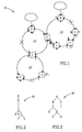
- Fig. 1 schematically illustrates an Ethernet network 10 comprising three interconnected ring networks 12, 14 and 16 including Ethernet switching nodes A, B, C, D, E, F, G, H, I. Each switching node is shown as a square. Ports of the nodes are shown by circles and numbered 1, 2, 3 and 4.
- VLAN1 for creating possible paths in the network between access edge port D3 and access edge port B3, and VLAN2 for creating possible paths between node/port G3 and node/port H3.
- VLAN2 for creating possible paths between node/port G3 and node/port H3.
- VLAN1 does not need to be configured at ports & switches associated with ring 16 since it is not encountered in the path of B3 to D3 in any possible topology that may be imposed by STP in this network. However, it will be shown that even in the case that VLAN1 has the illustrated redundant configuration, the proposed technique allows its optimization.
- Fig. 2 illustrates an STP tree 20 (the existing STP topology) created by the STP protocol on the network 10, taking into account the logical cuts (dotted crosses) on the spans AB, DE and GF.
- VLAN1 Ethernet packets transmitted between edges D3 and B3 will gradually find the only possible path D-C-B (black colored circles and black and white semicircles).
- VLAN2 packets sent from node G to node H the following path will be gradually learnt via the ports assigned to VLAN2 (white colored circles and black and white semicircles) : G_E_C_I_H.
- the function of the proposed protocol is to perform optimization of VLANs in a newly established STP network topology by deactivating such ports which do not need to serve for a given VLAN in the new (or changed) STP topology.
- Deactivating of the VLANs on ports is triggered by TCN & topology change timer expiry at so-called leaf nodes of the STP spanning tree, since at first (as soon as the topology change takes place) only leaf nodes may support a single forwarding port assigned to any VLAN, and such port is a typical dead-end port.
- the protocol proceeds by checking each of the switching nodes having at least one port assigned to a particular VLAN, to determine whether said port is a single forwarding port with respect to said particular VLAN, wherein any edge port is considered a forwarding port. If yes, the port creates and transmits a de-activation message to the associated port at a neighbor node. The neighbor node repeats the procedure and, if the conclusions are the same, also creates and transmits its de-activation message.
- Figs. 4a and 4b illustrate, in more detail, how the messages pass via the network when the proposed protocol reveals "dead ends" in a changed network topology.
- Fig. 4a illustrates the switching nodes A,B,C,D,E,F,G,H,I of the STP network topology 30 shown in Fig. 3.
- Four ports of each node of the nodes are shown by circles.
- Let Fig. 4a reflects the STP tree with respect to VLAN1, in which all ports of the nodes were initially assigned to VLAN1.
- switches F,G,I recognize that they only have a single forwarding point that is assigned to VLAN1.
- F,G and I each send a de-activation message PDU "deactivate VLAN1" to their designated nodes (switches), i.e., E and H respectively.
- switches i.e., E and H respectively.
- ports F1, G1, I1 are deactivated with respect to VLAN1.
- Switch E then deactivates VLAN1 on port 2 and port 4, as soon as each PDU is received and processed from G and F respectively.
- Switch E will follow the same procedure similarly as soon as it recognizes that El is a single forwarding port with respect to VLAN1.
- Switch H immediately deactivates VLAN1 on port 2.
- Node H since its port H1 becomes a single forwarding port, follows the same procedure similarly (i.e., deactivates H1 and forwards another PDU towards node A).
- the message "deactivate VLAN... " can be implemented as a single message for a particular port with respect to all VLANs that need to be deactivated at that port.
- the topology 30 is illustrated only with respect to VLAN1.
- Fig. 4b illustrates results of the VLAN1 pruning procedure. Due to the messages which were shown in Fig. 4a, nodes H, I, F, G, A and E are deactivated, i.e. neither of their ports is now assigned to VLAN1.
- Switch C deactivates VLAN1 on port 2, but does not include VLAN1 in the message to be sent to node B because VLAN1 is not deactivated on port 4.
- VLAN1 is configured as active only on switches D_C_B which are needed to connect edge ports at D and B, and only on the required ports.
- VLAN2 will be configured on switches G-E-C-B-A-H (white semicircles and circles, see Fig. 1), and de-activated (pruned) at other switches of the network which were active before the topology change. (The path between edge ports G3 and H3 has changed from G-E-C-I-H to G-E-C-B-A-H).
- the described procedure can be applied, as a supplementary protocol, to an Ethernet network having any degree of complexity and connectivity.
- the STP tree of the newly formed configuration will have active, with respect to a particular VLAN, only the switching nodes which, in the currently active STP topology, lie in the path connecting the terminal edge ports.
- the described pruning protocol should start only after resetting the initial assignments of switches/ports of the new topology to VLANs. In other words, any new optimization of the network should start not from the previously optimized one, but from the initial VLAN configuration.
Landscapes
- Engineering & Computer Science (AREA)
- Computer Networks & Wireless Communication (AREA)
- Signal Processing (AREA)
- Computer Security & Cryptography (AREA)
- Small-Scale Networks (AREA)
Claims (13)
- Ein Verfahren zur Verwendung eines Spanning Tree Protokolls, STP, in einem Ethernet-Netzwerk, worin eine Reihe von VLANs definiert sind und eine Vielzahl von Ethernet-Schaltknoten (A, B, C, D, E, F, G, H) über ihre Anschlüsse (A1, ..., H4) miteinander verbunden sind, so dass jeder der Anschlüsse ursprünglich einem oder mehreren VLANs zugeordnet ist und jedes der VLANs dazu dient, Verkehr zwischen zwei oder mehr Rand-Anschlüssen (D3, B3) zu ermöglichen, wobei das Verfahren dadurch gekennzeichnet ist, dass,
beim Festlegen einer neuen STP-Topologie (30), die mit einem oder mehreren VLANs zusammenhängt, es das Starten eines Abschneide-Verfahrens einer Broadcast-Domäne von mindestens einem des einen oder mehr VLANs umfasst, um einen Unterbaum für jedes abgeschnittene VLAN in der neuen STP-Topologie zu erhalten, worin jeder Unterbaum durch die Rand-Anschlüsse begrenzt ist, die dem entsprechenden abgeschnittenen VLAN zugeordnet wurden, wodurch Broadcast-Verkehr jedes abgeschnittenen VLANs zu jedem Ethernet-Schalter verhindert wird, der sich über den erhaltenen entsprechenden Unterbaum hinaus erstreckt. - Ein Verfahren gemäß Anspruch 1, dadurch gekennzeichnet, dass das Abschneide-Verfahren folgendes umfasst:Übertragen mindestens einer Deaktivierungsnachricht von mindestens einem Ethernet-Schaltknoten, der in der neuen STP-Topologie aktiv ist, an einen benachbarten Ethernet-Schaltknoten, der ebenfalls in der neuen STP-Topologie aktiv ist, anzeigend, dass ein oder mehrere VLANs für einen Anschluss, der die Nachricht sendet, deaktiviert wurden, um zu gestatten, dass das eine oder mehrere VLANs an einem Anschluss, der die Nachricht empfängt, deaktiviert werden.
- Das Verfahren gemäß Anspruch 2, das weiter die folgenden Schritte umfasst, die an jedem Ethernet-Schaltknoten durchgeführt werden sollen, der in der neuen STP-Topologie aktiv ist, und im Hinblick auf jedes der einen oder mehreren VLANs:a) Sicherstellen, dass Anschlüsse des Ethernet-Schaltknotens, der in der neuen STP-Topologie aktiv ist, dem einem oder den mehreren VLANs entsprechend einer ursprünglichen VLANs-Konfiguration zugeordnet sind;b) Zählen von Weiterleitungs-Anschlüssen, die einem bestimmten VLAN zugeordnet wurden, die gemäß der neuen STP-Topologie aktiv sind;c) wenn ein Anschluss, der einem bestimmten VLAN zugeordnet wurde, ein einzelner Weiterleitungs-Anschluss für den bestimmten VLAN an dem Knoten ist, Deaktivieren des Anschlusses für das VLAN, wodurch das VLAN an dem Anschluss und an dem Knoten abgeschnitten wird;d) Erzeugen der Deaktivierungsnachricht von jedem einzelnen Weiterleitungs-Anschluss des Knotens, wobei die Nachricht einen oder mehrere VLANs als an dem Anschluss deaktiviert anzeigt, zum Übertragen der Deaktivierungsnachricht an einen benachbarten Ethernet-Schaltknoten in der neuen STP-Topologie;e) Deaktivieren des Anschlusses des benachbarten Ethernet-Schalters, welcher die Deaktivierungsnachricht erhalten hat, im Hinblick auf den einen oder die mehreren VLANs, die in der Nachricht angegeben sind;f) Wiederholen der Schritte b) bis e) an dem benachbarten Knoten.
- Das Verfahren gemäß einem beliebigen der obigen Ansprüche, worin die neue STP-Topologie die ursprüngliche STP-Topologie im Ethernet-Netzwerk ist.
- Das Verfahren gemäß einem beliebigen der Ansprüche 1 bis 3, worin die neue STP-Topologie eine geänderte STP-Topologie im Ethernet-Netzwerk ist.
- Das Verfahren gemäß einem beliebigen der Ansprüche 3 bis 5, worin im Zählschritt die Rand-Anschlüsse als permanent weiterleitende Anschlüsse betrachtet werden.
- Das Verfahren gemäß einem beliebigen der Ansprüche 2 bis 6, worin die Deaktivierungsnachricht eine Protokoll-Daten-Einheit-Nachricht (PDU-Nachricht) ist, die weiter mit einer Angabe eines oder mehrerer spezieller VLANs versehen ist, für welche der Anschluss deaktiviert wird.
- Das Verfahren gemäß Anspruch 7, worin die PDU-Nachricht eine kombinierte Deaktivierungsnachricht ist, welche alle VLANs aufzählt, die an dem Anschluss deaktiviert werden.
- Das Verfahren gemäß einem beliebigen der obigen Ansprüche, das bei jedem speziellen Ethernet-Schaltknoten beim Erhalt einer Topologie-Änderungs-Benachrichtigung, TCN, und nach Ablauf eines Topologie-Änderungs-Timers gestartet wird.
- Ein Software-Produkt, das Software-implementierbare Anweisungen und/oder Daten zur Durchführung eines Verfahrens gemäß einem beliebigen der obigen Ansprüche umfasst.
- Ein Trägermedium, das ein Software-Produkt gemäß Anspruch 10 umfasst.
- Ein Ethernet-Schalter, der in der Lage ist, das Software-Produkt von Anspruch 10 zu implementieren.
- Ein Ethernet-Schalter, der in der Lage ist, das Verfahren gemäß einem beliebigen der Ansprüche 1 bis 9 durchzuführen.
Applications Claiming Priority (2)
| Application Number | Priority Date | Filing Date | Title |
|---|---|---|---|
| IL155449A IL155449A (en) | 2003-04-15 | 2003-04-15 | Technology for improving stp protocols in ethernet networks supporting vlans |
| IL15544903 | 2003-04-15 |
Publications (2)
| Publication Number | Publication Date |
|---|---|
| EP1469639A1 EP1469639A1 (de) | 2004-10-20 |
| EP1469639B1 true EP1469639B1 (de) | 2006-05-24 |
Family
ID=32894020
Family Applications (1)
| Application Number | Title | Priority Date | Filing Date |
|---|---|---|---|
| EP04008847A Expired - Lifetime EP1469639B1 (de) | 2003-04-15 | 2004-04-14 | Verfahren, Softwareprodukt, Speichermedium und Ethernetswitch zur Verbesserung des STP Protokolls in VLAN Ethernet Netzwerken |
Country Status (8)
| Country | Link |
|---|---|
| US (1) | US7551571B2 (de) |
| EP (1) | EP1469639B1 (de) |
| CN (1) | CN100531196C (de) |
| AT (1) | ATE327619T1 (de) |
| AU (1) | AU2004201384B2 (de) |
| CA (1) | CA2463440C (de) |
| DE (1) | DE602004000943T2 (de) |
| IL (1) | IL155449A (de) |
Cited By (1)
| Publication number | Priority date | Publication date | Assignee | Title |
|---|---|---|---|---|
| CN101483575B (zh) * | 2008-01-08 | 2011-11-16 | 阿尔卡特朗讯公司 | 用于保护由生成树协议建立的网络构造的方法 |
Families Citing this family (23)
| Publication number | Priority date | Publication date | Assignee | Title |
|---|---|---|---|---|
| US7877483B1 (en) * | 2002-10-28 | 2011-01-25 | Cisco Technology, Inc. | Virtual local area network pruning protocol |
| US8260932B2 (en) | 2005-04-27 | 2012-09-04 | International Business Machines Corporation | Using broadcast domains to manage virtual local area networks |
| US20060245354A1 (en) * | 2005-04-28 | 2006-11-02 | International Business Machines Corporation | Method and apparatus for deploying and instantiating multiple instances of applications in automated data centers using application deployment template |
| US7606178B2 (en) * | 2005-05-31 | 2009-10-20 | Cisco Technology, Inc. | Multiple wireless spanning tree protocol for use in a wireless mesh network |
| EP1746784A1 (de) * | 2005-07-22 | 2007-01-24 | Siemens Aktiengesellschaft | Methoden zur Optimierung der Nutzung von Ressourcen zur Absicherung eines Ethernet Rings |
| US7821972B1 (en) * | 2005-09-29 | 2010-10-26 | Cisco Technology, Inc. | System and method for building large-scale layer 2 computer networks |
| CN100433723C (zh) * | 2006-03-14 | 2008-11-12 | 杭州华三通信技术有限公司 | 一种虚拟局域网中的广播报文跨该虚拟局域网广播的方法 |
| US7940700B2 (en) * | 2007-01-31 | 2011-05-10 | Hewlett-Packard Development Company, L.P. | Method of distributing multiple spanning tree protocol configuration |
| CN100461743C (zh) * | 2007-03-20 | 2009-02-11 | 杭州华三通信技术有限公司 | 一种快速迁移的方法和交换机 |
| US7869439B1 (en) * | 2007-04-16 | 2011-01-11 | World Wide Packets, Inc. | Varying packet switch behavior based on a quantity of virtual interfaces associated with a virtual switch |
| CN101207521A (zh) * | 2007-12-12 | 2008-06-25 | 华为技术有限公司 | 以太网故障检测及收敛的方法和节点设备 |
| CN101296188B (zh) * | 2008-06-16 | 2010-10-27 | 杭州华三通信技术有限公司 | 在两级分布式设备上实现快速生成树协议的方法 |
| US7881228B2 (en) * | 2008-07-23 | 2011-02-01 | Hewlett-Packard Development Company, L.P. | System and method for broadcast pruning in Ethernet based provider bridging network |
| CN101646256B (zh) * | 2009-09-04 | 2012-06-27 | 华为技术有限公司 | 跨无线接入技术的语音切换方法、设备及网络系统 |
| US8873431B1 (en) * | 2010-04-08 | 2014-10-28 | Adtran, Inc. | Communications system and method for maintaining topology in a VLAN environment |
| US8812708B2 (en) * | 2011-07-22 | 2014-08-19 | Cisco Technology, Inc. | Transient unpruning for faster layer-two convergence |
| US9252970B2 (en) * | 2011-12-27 | 2016-02-02 | Intel Corporation | Multi-protocol I/O interconnect architecture |
| US9131014B2 (en) | 2012-08-20 | 2015-09-08 | Cisco Technology, Inc. | Hitless pruning protocol upgrade on single supervisor network devices |
| US20150215164A1 (en) * | 2012-08-24 | 2015-07-30 | Nec Corporation | Information processing device |
| CN102891778B (zh) * | 2012-09-27 | 2016-03-30 | 迈普通信技术股份有限公司 | 自动化测试中避免环路的控制系统及方法 |
| US11251864B1 (en) * | 2020-07-01 | 2022-02-15 | Amazon Technologies, Inc. | Logical cut of an optical fiber due to fiber events |
| CN113411220A (zh) * | 2021-06-30 | 2021-09-17 | 新华三技术有限公司 | 一种生成树协议边缘端口配置方法及装置 |
| CN114070788B (zh) * | 2021-11-05 | 2023-03-24 | 电信科学技术第五研究所有限公司 | 交换机在不支持stp的交换芯片下实现stp的方法 |
Family Cites Families (15)
| Publication number | Priority date | Publication date | Assignee | Title |
|---|---|---|---|---|
| US6188694B1 (en) * | 1997-12-23 | 2001-02-13 | Cisco Technology, Inc. | Shared spanning tree protocol |
| US6898189B1 (en) * | 2000-08-23 | 2005-05-24 | Cisco Technology, Inc. | Restartable spanning tree for high availability network systems |
| US6611502B1 (en) * | 1999-01-15 | 2003-08-26 | 3Com Corportion | Spanning tree with rapid propagation of topology changes |
| US6771610B1 (en) * | 1999-01-19 | 2004-08-03 | 3Com Corporation | Spanning tree with protocol for bypassing port state transition timers |
| US6515969B1 (en) * | 1999-03-01 | 2003-02-04 | Cisco Technology, Inc. | Virtual local area network membership registration protocol for multiple spanning tree network environments |
| US6535490B1 (en) * | 1999-03-04 | 2003-03-18 | 3Com Corporation | High availability spanning tree with rapid reconfiguration with alternate port selection |
| US6678241B1 (en) * | 1999-11-30 | 2004-01-13 | Cisc Technology, Inc. | Fast convergence with topology switching |
| JP3664935B2 (ja) * | 2000-03-17 | 2005-06-29 | アンリツ株式会社 | スパニングツリープロトコルを用いたブリッジ経路決定方法及びスパニングツリープロトコルを備えたブリッジ |
| US6954437B1 (en) * | 2000-06-30 | 2005-10-11 | Intel Corporation | Method and apparatus for avoiding transient loops during network topology adoption |
| US6934262B1 (en) * | 2000-08-26 | 2005-08-23 | Cisco Technology, Inc. | Method and apparatus for restricting the assignment of VLANs |
| US6987740B1 (en) * | 2000-09-11 | 2006-01-17 | Cisco Technology, Inc. | STP root guard |
| WO2002032058A2 (en) * | 2000-10-13 | 2002-04-18 | General Instrument Corporation | Spanning tree alternate routing bridge protocol |
| US7061875B1 (en) * | 2001-12-07 | 2006-06-13 | Cisco Technology, Inc. | Spanning tree loop guard |
| US20030223379A1 (en) * | 2002-05-28 | 2003-12-04 | Xuguang Yang | Method and system for inter-domain loop protection using a hierarchy of loop resolving protocols |
| JP3799010B2 (ja) * | 2002-12-19 | 2006-07-19 | アンリツ株式会社 | メッシュ型ネットワーク用ブリッジ |
-
2003
- 2003-04-15 IL IL155449A patent/IL155449A/en not_active IP Right Cessation
-
2004
- 2004-04-01 AU AU2004201384A patent/AU2004201384B2/en not_active Ceased
- 2004-04-02 CA CA002463440A patent/CA2463440C/en not_active Expired - Fee Related
- 2004-04-14 DE DE602004000943T patent/DE602004000943T2/de not_active Expired - Lifetime
- 2004-04-14 EP EP04008847A patent/EP1469639B1/de not_active Expired - Lifetime
- 2004-04-14 AT AT04008847T patent/ATE327619T1/de not_active IP Right Cessation
- 2004-04-15 US US10/824,378 patent/US7551571B2/en active Active
- 2004-04-15 CN CN200410090040.6A patent/CN100531196C/zh not_active Expired - Fee Related
Cited By (1)
| Publication number | Priority date | Publication date | Assignee | Title |
|---|---|---|---|---|
| CN101483575B (zh) * | 2008-01-08 | 2011-11-16 | 阿尔卡特朗讯公司 | 用于保护由生成树协议建立的网络构造的方法 |
Also Published As
| Publication number | Publication date |
|---|---|
| CA2463440C (en) | 2009-09-01 |
| CN100531196C (zh) | 2009-08-19 |
| CN1599375A (zh) | 2005-03-23 |
| IL155449A (en) | 2008-06-05 |
| DE602004000943T2 (de) | 2007-05-03 |
| EP1469639A1 (de) | 2004-10-20 |
| AU2004201384B2 (en) | 2009-02-19 |
| DE602004000943D1 (de) | 2006-06-29 |
| US20040218551A1 (en) | 2004-11-04 |
| US7551571B2 (en) | 2009-06-23 |
| CA2463440A1 (en) | 2004-10-15 |
| ATE327619T1 (de) | 2006-06-15 |
| AU2004201384A1 (en) | 2004-11-04 |
Similar Documents
| Publication | Publication Date | Title |
|---|---|---|
| EP1469639B1 (de) | Verfahren, Softwareprodukt, Speichermedium und Ethernetswitch zur Verbesserung des STP Protokolls in VLAN Ethernet Netzwerken | |
| US5878232A (en) | Dynamic reconfiguration of network device's virtual LANs using the root identifiers and root ports determined by a spanning tree procedure | |
| EP2533475B1 (de) | Verfahren und system für host-routenerreichbarkeit in einem zugangsring eines pakettransportnetzwerkes | |
| JP5106100B2 (ja) | アドレス型キャリアネットワークにおける区別転送 | |
| EP2643940B1 (de) | Verfahren zum schrumpfen eines datenverlustfensters in einer paketnetzvorrichtung | |
| US20090310481A1 (en) | Method and device of network protection | |
| US20140140243A1 (en) | Method and apparatus for layer 2 fast re-configuration in a routing bridge network | |
| US20070014234A1 (en) | Loop prevention system and method in a stackable ethernet switch system | |
| KR20090089385A (ko) | 해시 기반 멀티호밍 | |
| US7822049B1 (en) | System and method for enabling a remote instance of a loop avoidance protocol | |
| WO2007083311A2 (en) | Vpls failure protection in ring networks | |
| US8619632B2 (en) | Communications network with enhanced notification for topology change | |
| US7821920B2 (en) | Flushing processing unit and method of switching device in network using spanning tree protocol | |
| RU2641483C2 (ru) | Управление ошибками соединения в сети связи | |
| US8687519B2 (en) | Forced medium access control (MAC) learning in bridged ethernet networks | |
| CN1825832B (zh) | 快速环生成树协议 | |
| EP1359715B1 (de) | Verfahren zum Aufbau eines schleifenfreien Pfades zur Übertragung von Datenpaketen in einem Ringnetz | |
| EP2929659A1 (de) | Verfahren zur automatischen detektion physikalischer verbindungen von ethernetbrücken mit einer basisbrücke | |
| EP1913736B1 (de) | Spanning Tree BPDU VERARBEITUNGSVERFAHREN UND GERÄT ZUR LEICHTEN INTEGRATION VON VERSCHIEDENEN URSPRÜNGLICHEN VLAN-KONFIGURATIONEN | |
| US8331360B1 (en) | Method and apparatus for layer 2 fast re-configuration in a routing bridge network | |
| Kasu et al. | Spanning tree protocol | |
| US11025527B2 (en) | Topology change processing in bridged networks using a spanning tree protocol | |
| EP1722517B1 (de) | Kommunikationssystem und Verfahren zur Kontrolle des Datenflusses durch Blockieren eines Ports | |
| Son et al. | Multiple spanning tree protocols in 10-Gb Ethernet edge system |
Legal Events
| Date | Code | Title | Description |
|---|---|---|---|
| PUAI | Public reference made under article 153(3) epc to a published international application that has entered the european phase |
Free format text: ORIGINAL CODE: 0009012 |
|
| AK | Designated contracting states |
Kind code of ref document: A1 Designated state(s): AT BE BG CH CY CZ DE DK EE ES FI FR GB GR HU IE IT LI LU MC NL PL PT RO SE SI SK TR |
|
| AX | Request for extension of the european patent |
Extension state: AL HR LT LV MK |
|
| 17P | Request for examination filed |
Effective date: 20041006 |
|
| RTI1 | Title (correction) |
Free format text: TECHNOLOGY FOR IMPROVING STP PROTOCOLS IN ETHENET NETWORKS SUPPORTING VLANS |
|
| 17Q | First examination report despatched |
Effective date: 20050112 |
|
| AKX | Designation fees paid |
Designated state(s): AT BE BG CH CY CZ DE DK EE ES FI FR GB GR HU IE IT LI LU MC NL PL PT RO SE SI SK TR |
|
| GRAP | Despatch of communication of intention to grant a patent |
Free format text: ORIGINAL CODE: EPIDOSNIGR1 |
|
| RTI1 | Title (correction) |
Free format text: METHOD, SOFTWARE PRODUCT, CARRIER MEDIUM AND ETHERNET SWITCH FOR IMPROVING STP PROTOCOLS IN ETHERNET NETWORKS SUPPORTING |
|
| GRAS | Grant fee paid |
Free format text: ORIGINAL CODE: EPIDOSNIGR3 |
|
| GRAA | (expected) grant |
Free format text: ORIGINAL CODE: 0009210 |
|
| AK | Designated contracting states |
Kind code of ref document: B1 Designated state(s): AT BE BG CH CY CZ DE DK EE ES FI FR GB GR HU IE IT LI LU MC NL PL PT RO SE SI SK TR |
|
| PG25 | Lapsed in a contracting state [announced via postgrant information from national office to epo] |
Ref country code: IT Free format text: LAPSE BECAUSE OF FAILURE TO SUBMIT A TRANSLATION OF THE DESCRIPTION OR TO PAY THE FEE WITHIN THE PRESCRIBED TIME-LIMIT;WARNING: LAPSES OF ITALIAN PATENTS WITH EFFECTIVE DATE BEFORE 2007 MAY HAVE OCCURRED AT ANY TIME BEFORE 2007. THE CORRECT EFFECTIVE DATE MAY BE DIFFERENT FROM THE ONE RECORDED. Effective date: 20060524 Ref country code: SI Free format text: LAPSE BECAUSE OF FAILURE TO SUBMIT A TRANSLATION OF THE DESCRIPTION OR TO PAY THE FEE WITHIN THE PRESCRIBED TIME-LIMIT Effective date: 20060524 Ref country code: RO Free format text: LAPSE BECAUSE OF FAILURE TO SUBMIT A TRANSLATION OF THE DESCRIPTION OR TO PAY THE FEE WITHIN THE PRESCRIBED TIME-LIMIT Effective date: 20060524 Ref country code: SK Free format text: LAPSE BECAUSE OF FAILURE TO SUBMIT A TRANSLATION OF THE DESCRIPTION OR TO PAY THE FEE WITHIN THE PRESCRIBED TIME-LIMIT Effective date: 20060524 Ref country code: LI Free format text: LAPSE BECAUSE OF FAILURE TO SUBMIT A TRANSLATION OF THE DESCRIPTION OR TO PAY THE FEE WITHIN THE PRESCRIBED TIME-LIMIT Effective date: 20060524 Ref country code: FI Free format text: LAPSE BECAUSE OF FAILURE TO SUBMIT A TRANSLATION OF THE DESCRIPTION OR TO PAY THE FEE WITHIN THE PRESCRIBED TIME-LIMIT Effective date: 20060524 Ref country code: BE Free format text: LAPSE BECAUSE OF FAILURE TO SUBMIT A TRANSLATION OF THE DESCRIPTION OR TO PAY THE FEE WITHIN THE PRESCRIBED TIME-LIMIT Effective date: 20060524 Ref country code: CZ Free format text: LAPSE BECAUSE OF FAILURE TO SUBMIT A TRANSLATION OF THE DESCRIPTION OR TO PAY THE FEE WITHIN THE PRESCRIBED TIME-LIMIT Effective date: 20060524 Ref country code: AT Free format text: LAPSE BECAUSE OF FAILURE TO SUBMIT A TRANSLATION OF THE DESCRIPTION OR TO PAY THE FEE WITHIN THE PRESCRIBED TIME-LIMIT Effective date: 20060524 Ref country code: CH Free format text: LAPSE BECAUSE OF FAILURE TO SUBMIT A TRANSLATION OF THE DESCRIPTION OR TO PAY THE FEE WITHIN THE PRESCRIBED TIME-LIMIT Effective date: 20060524 Ref country code: NL Free format text: LAPSE BECAUSE OF FAILURE TO SUBMIT A TRANSLATION OF THE DESCRIPTION OR TO PAY THE FEE WITHIN THE PRESCRIBED TIME-LIMIT Effective date: 20060524 Ref country code: PL Free format text: LAPSE BECAUSE OF FAILURE TO SUBMIT A TRANSLATION OF THE DESCRIPTION OR TO PAY THE FEE WITHIN THE PRESCRIBED TIME-LIMIT Effective date: 20060524 |
|
| REG | Reference to a national code |
Ref country code: GB Ref legal event code: FG4D |
|
| REG | Reference to a national code |
Ref country code: CH Ref legal event code: EP |
|
| REG | Reference to a national code |
Ref country code: IE Ref legal event code: FG4D |
|
| REF | Corresponds to: |
Ref document number: 602004000943 Country of ref document: DE Date of ref document: 20060629 Kind code of ref document: P |
|
| PG25 | Lapsed in a contracting state [announced via postgrant information from national office to epo] |
Ref country code: DK Free format text: LAPSE BECAUSE OF FAILURE TO SUBMIT A TRANSLATION OF THE DESCRIPTION OR TO PAY THE FEE WITHIN THE PRESCRIBED TIME-LIMIT Effective date: 20060824 Ref country code: SE Free format text: LAPSE BECAUSE OF FAILURE TO SUBMIT A TRANSLATION OF THE DESCRIPTION OR TO PAY THE FEE WITHIN THE PRESCRIBED TIME-LIMIT Effective date: 20060824 |
|
| PG25 | Lapsed in a contracting state [announced via postgrant information from national office to epo] |
Ref country code: ES Free format text: LAPSE BECAUSE OF FAILURE TO SUBMIT A TRANSLATION OF THE DESCRIPTION OR TO PAY THE FEE WITHIN THE PRESCRIBED TIME-LIMIT Effective date: 20060904 |
|
| PG25 | Lapsed in a contracting state [announced via postgrant information from national office to epo] |
Ref country code: PT Free format text: LAPSE BECAUSE OF FAILURE TO SUBMIT A TRANSLATION OF THE DESCRIPTION OR TO PAY THE FEE WITHIN THE PRESCRIBED TIME-LIMIT Effective date: 20061024 |
|
| NLV1 | Nl: lapsed or annulled due to failure to fulfill the requirements of art. 29p and 29m of the patents act | ||
| REG | Reference to a national code |
Ref country code: CH Ref legal event code: PL |
|
| PLBE | No opposition filed within time limit |
Free format text: ORIGINAL CODE: 0009261 |
|
| STAA | Information on the status of an ep patent application or granted ep patent |
Free format text: STATUS: NO OPPOSITION FILED WITHIN TIME LIMIT |
|
| 26N | No opposition filed |
Effective date: 20070227 |
|
| EN | Fr: translation not filed | ||
| PG25 | Lapsed in a contracting state [announced via postgrant information from national office to epo] |
Ref country code: GR Free format text: LAPSE BECAUSE OF FAILURE TO SUBMIT A TRANSLATION OF THE DESCRIPTION OR TO PAY THE FEE WITHIN THE PRESCRIBED TIME-LIMIT Effective date: 20060825 Ref country code: FR Free format text: LAPSE BECAUSE OF FAILURE TO SUBMIT A TRANSLATION OF THE DESCRIPTION OR TO PAY THE FEE WITHIN THE PRESCRIBED TIME-LIMIT Effective date: 20070309 |
|
| PG25 | Lapsed in a contracting state [announced via postgrant information from national office to epo] |
Ref country code: IE Free format text: LAPSE BECAUSE OF NON-PAYMENT OF DUE FEES Effective date: 20070416 |
|
| PG25 | Lapsed in a contracting state [announced via postgrant information from national office to epo] |
Ref country code: BG Free format text: LAPSE BECAUSE OF FAILURE TO SUBMIT A TRANSLATION OF THE DESCRIPTION OR TO PAY THE FEE WITHIN THE PRESCRIBED TIME-LIMIT Effective date: 20060824 |
|
| PG25 | Lapsed in a contracting state [announced via postgrant information from national office to epo] |
Ref country code: EE Free format text: LAPSE BECAUSE OF FAILURE TO SUBMIT A TRANSLATION OF THE DESCRIPTION OR TO PAY THE FEE WITHIN THE PRESCRIBED TIME-LIMIT Effective date: 20060524 |
|
| PG25 | Lapsed in a contracting state [announced via postgrant information from national office to epo] |
Ref country code: FR Free format text: LAPSE BECAUSE OF FAILURE TO SUBMIT A TRANSLATION OF THE DESCRIPTION OR TO PAY THE FEE WITHIN THE PRESCRIBED TIME-LIMIT Effective date: 20060524 |
|
| GBPC | Gb: european patent ceased through non-payment of renewal fee |
Effective date: 20080414 |
|
| PG25 | Lapsed in a contracting state [announced via postgrant information from national office to epo] |
Ref country code: MC Free format text: LAPSE BECAUSE OF NON-PAYMENT OF DUE FEES Effective date: 20070430 |
|
| PG25 | Lapsed in a contracting state [announced via postgrant information from national office to epo] |
Ref country code: GB Free format text: LAPSE BECAUSE OF NON-PAYMENT OF DUE FEES Effective date: 20080414 |
|
| PG25 | Lapsed in a contracting state [announced via postgrant information from national office to epo] |
Ref country code: LU Free format text: LAPSE BECAUSE OF NON-PAYMENT OF DUE FEES Effective date: 20070414 Ref country code: CY Free format text: LAPSE BECAUSE OF FAILURE TO SUBMIT A TRANSLATION OF THE DESCRIPTION OR TO PAY THE FEE WITHIN THE PRESCRIBED TIME-LIMIT Effective date: 20060524 |
|
| PG25 | Lapsed in a contracting state [announced via postgrant information from national office to epo] |
Ref country code: HU Free format text: LAPSE BECAUSE OF FAILURE TO SUBMIT A TRANSLATION OF THE DESCRIPTION OR TO PAY THE FEE WITHIN THE PRESCRIBED TIME-LIMIT Effective date: 20061125 Ref country code: TR Free format text: LAPSE BECAUSE OF FAILURE TO SUBMIT A TRANSLATION OF THE DESCRIPTION OR TO PAY THE FEE WITHIN THE PRESCRIBED TIME-LIMIT Effective date: 20060524 |
|
| PGFP | Annual fee paid to national office [announced via postgrant information from national office to epo] |
Ref country code: DE Payment date: 20130322 Year of fee payment: 10 |
|
| REG | Reference to a national code |
Ref country code: DE Ref legal event code: R119 Ref document number: 602004000943 Country of ref document: DE |
|
| PG25 | Lapsed in a contracting state [announced via postgrant information from national office to epo] |
Ref country code: DE Free format text: LAPSE BECAUSE OF NON-PAYMENT OF DUE FEES Effective date: 20141101 |
|
| REG | Reference to a national code |
Ref country code: DE Ref legal event code: R119 Ref document number: 602004000943 Country of ref document: DE Effective date: 20141101 |