EP1544993A2 - Baureihe von elektrischen Stellantrieben für Türen und Verfahren zur Realisierung dieser Baureihe - Google Patents
Baureihe von elektrischen Stellantrieben für Türen und Verfahren zur Realisierung dieser Baureihe Download PDFInfo
- Publication number
- EP1544993A2 EP1544993A2 EP04029789A EP04029789A EP1544993A2 EP 1544993 A2 EP1544993 A2 EP 1544993A2 EP 04029789 A EP04029789 A EP 04029789A EP 04029789 A EP04029789 A EP 04029789A EP 1544993 A2 EP1544993 A2 EP 1544993A2
- Authority
- EP
- European Patent Office
- Prior art keywords
- range
- actuator
- converter
- actuators
- nominal
- Prior art date
- Legal status (The legal status is an assumption and is not a legal conclusion. Google has not performed a legal analysis and makes no representation as to the accuracy of the status listed.)
- Withdrawn
Links
- 238000000034 method Methods 0.000 title claims description 10
- 238000004519 manufacturing process Methods 0.000 claims abstract description 8
- 238000004804 winding Methods 0.000 claims description 15
- 230000037072 sun protection Effects 0.000 claims 1
- 239000003990 capacitor Substances 0.000 abstract description 4
- 238000010586 diagram Methods 0.000 description 5
- 239000000463 material Substances 0.000 description 2
- 230000004048 modification Effects 0.000 description 2
- 238000012986 modification Methods 0.000 description 2
- 230000007935 neutral effect Effects 0.000 description 2
- 238000004513 sizing Methods 0.000 description 2
- 230000000903 blocking effect Effects 0.000 description 1
- 230000001419 dependent effect Effects 0.000 description 1
- 239000006185 dispersion Substances 0.000 description 1
- 238000005265 energy consumption Methods 0.000 description 1
- 230000005294 ferromagnetic effect Effects 0.000 description 1
- 230000001360 synchronised effect Effects 0.000 description 1
Images
Classifications
-
- E—FIXED CONSTRUCTIONS
- E05—LOCKS; KEYS; WINDOW OR DOOR FITTINGS; SAFES
- E05F—DEVICES FOR MOVING WINGS INTO OPEN OR CLOSED POSITION; CHECKS FOR WINGS; WING FITTINGS NOT OTHERWISE PROVIDED FOR, CONCERNED WITH THE FUNCTIONING OF THE WING
- E05F15/00—Power-operated mechanisms for wings
- E05F15/60—Power-operated mechanisms for wings using electrical actuators
- E05F15/603—Power-operated mechanisms for wings using electrical actuators using rotary electromotors
Definitions
- the invention relates to a range of actuators according to the preamble of claim 1. It still relates to a method of making of a range of electric actuators, a method of producing a electric actuator and an actuator made according to this method.
- Doors fitted to buildings or gates have varied dimensions and the choice of materials used is reflected considerably on the mass and inertia of moving parts and, consequently, on the torques necessary to maneuver them. In some cases, compensation schemes are provided for counterweight or springs.
- the actuators most often comprise a motor of the type to DC current that is powered from the AC network through a continuous AC converter.
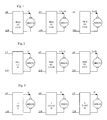
- the supply of increasing power can then be offered either by the actuator range structure presented in Figure 1, either by the actuator range structure presented at figure 2.
- the current motors continuous MDC11, MDC12 and MDC13 have the same rated voltage U1 and their nominal intensity is for example respectively I1, 1.5 x I1 and 2 x I1.
- the PS 10 converter used must be able to provide the most important of the three currents. It is therefore oversized in cases where it is used to power the MDC11 and MDC12 engines. This is all more economically penalizing than low power actuators generally correspond to the largest quantities requested by the market.
- a known solution to the previous problem is to use the range actuators shown in Figure 2.
- This range uses the same MDC21, MDC22 and MDC23 motors than those used in the range previous, respectively MDC11, MDC12 and MDC13.
- each PS21, PS22 and PS23 converter is respectively sized to provide, for example, under the same DC voltage U1, a rated current I1, 1.5 x I1 or 2 x I1.
- U1 DC voltage
- I1 1.5 x I1
- 2 x I1 1.5 x I1
- this solution is a problem. Indeed, it is necessary organize the manufacture of different converters. This results in a cost multiple reference management for the manufacturer and a dispersion of production volumes increasing the unit price of converters and therefore that of the actuators.
- a maneuvering device of a closure element comprises an electric motor DC powered by an AC-DC converter whose entrance is connected to the sector.
- the converter includes a means of adjusting the output voltage of the converter acting on a controlled switch. This means of adjusting the voltage supply allows the motor to run at different speeds to drive the closure element at different speeds.
- the object of the invention is to provide a range of actuators improving known actuator ranges and providing a solution to the problem supra.
- the invention makes it possible to reduce management costs and manufacturing the range of actuators.
- the range of electric actuators according to the invention is characterized by the characterizing part of claim 1.
- power components are usually grouped into two voltage classes, LV (low voltage) and TBT (very low voltage), and that within the TBT class, it is the intensity that dimension the components.
- LV low voltage
- TBT very low voltage
- a 60V transistor may indifferently work at voltages of 24 or 48 V, but it will choose different components depending on whether the rated current is 10 or 20 A.
- the method of producing a range of electric actuators according to the invention is characterized by the characterizing part of the claim 7.
- the method of producing an electric actuator according to the invention is characterized by the characterizing part of claim 8.
- the actuator according to the invention is produced according to the defined method previously.
- the invention also relates to an actuator of a range of actuators carried out according to the method defined above.
- the attached drawing represents, by way of example, two modes of embodiment of a range of actuators according to the invention.
- FIG. 1 is a diagram of a first range of actuators of different powers known from the prior art.
- FIG. 2 is a diagram of a second range of actuators of different powers known from the prior art.
- FIG. 3 is a diagram of a range of power actuators different according to the invention.
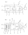
- FIG. 4 is a diagram of one of the actuators composing a range according to a first embodiment.
- FIG. 5 is a diagram of one of the actuators composing a range according to a second embodiment.
- the range shown in Figure 3 is composed of three actuators of respective powers PM, 1.5 x PM and 2 x PM.
- the converters 3 have the same structure and in particular the same power components. They provide, by simple modification or setting of a control circuit any of the three nominal voltages of the MDC31, MDC32 or MDC 33 motors. it is therefore not necessary to replace such a component that a transformer or a power transistor, influencing the sizing and the cost of such a converter.
- An actuator 1 according to a first embodiment is represented more in detail in Figure 4. This actuator is powered by the mains represented by the LP and LN neutral phase wires. It allows to operate a door 2.
- the actuator 1 comprises an AC / DC converter 3a and a DC motor 4.
- the converter is of the switching type.
- the mains voltage is rectified by a rectifying device 7 and is used to charge a capacitor 8 disposed between the terminals output of the converter 3a.
- the charge of capacitor 8 is controlled by a transistor 5 controlled by a control circuit 6.
- This control circuit includes a selector 9 for adjusting the voltage Release. The selector makes it possible to act on the conditions of blocking and turning on the transistor.
- the adjustment of the output voltage of the converter 3a can in particular be performed by manipulating a switch or moving a setting jumper.
- Any AC-DC converter may be suitable for implementation of the invention, provided that its structure allows a great dynamic output voltage without having to modify the components of its power circuit.
- the converter is of the "synchronous" type by sector.
- it contains a switch controlled at a frequency equal to once or twice the frequency sector.
- Such a converter is described in detail in the patent US 4,001,668 or pages 5-11 of the application WO 03/030344. These converters are characterized by a great dynamic in tension output or input voltage.
- a second embodiment of actuator 1 ' is shown in FIG. Figure 5. This actuator is powered by the sector represented by the wires LP phase and LN neutral. It allows to operate a door 2.
- the actuator 1 comprises an AC / DC converter 3b and a DC motor 4.
- the converter 3b is of type transformer and rectifier.
- the AC voltage of the sector is lowered by a transformer 10, then is rectified by a device rectifier 14 such as a diode bridge for charging a capacitor 8 disposed between the output terminals of the converter 3b.
- the transformer 10 comprises a carcass of material ferromagnetic around which are wound a primary winding 11 powered by the mains voltage and three secondary windings 12a, 12b and 12c. These windings can, thanks to means of connection 13, be connected in different configurations for supply the rectifier device under three different voltages. For change the output voltage of such a converter, just change the state of switches resulting in a different connection the different secondary windings between them.
- a selector 15 makes it possible to control the state of switches (no shown) in the connection means 13 to output the desired voltage.
- the different secondary windings may consist of coils of the same number of turns.
- three windings are selected coils of the same number of turns and connect one, two or three of these windings in parallel to the input of the rectifier to feed a 12V motor, two of these series windings are connected to the rectifier input to power a 24V motor and connect the three windings in series at the input of the rectifier to power a 36V motor.
- two secondary windings of number of different turns, giving respectively 12V and 24V voltages.
- the means of connection 13 then make it possible to select one of the two windings or carry out their serialization.
- the transformer may present several primary windings and a secondary winding.
- the different primary windings are then connected to the sector according to different configurations to obtain the desired output voltage.
- This variant has a disadvantage. Constraints of sizing require the realization of a transformer whose Empty energy consumption is important.
Landscapes
- Control Of Multiple Motors (AREA)
- Power-Operated Mechanisms For Wings (AREA)
Applications Claiming Priority (4)
| Application Number | Priority Date | Filing Date | Title |
|---|---|---|---|
| FR0315065 | 2003-12-19 | ||
| FR0315065A FR2864365A1 (fr) | 2003-12-19 | 2003-12-19 | Gamme d'actionneurs electriques pour portes et procede de realisation de cette gamme |
| FR0401227 | 2004-02-09 | ||
| FR0401227A FR2864366B1 (fr) | 2003-12-19 | 2004-02-09 | Gamme d'actionneurs electriques pour portes et procede de realisation de cette gamme |
Publications (2)
| Publication Number | Publication Date |
|---|---|
| EP1544993A2 true EP1544993A2 (de) | 2005-06-22 |
| EP1544993A3 EP1544993A3 (de) | 2005-11-16 |
Family
ID=34525007
Family Applications (1)
| Application Number | Title | Priority Date | Filing Date |
|---|---|---|---|
| EP04029789A Withdrawn EP1544993A3 (de) | 2003-12-19 | 2004-12-16 | Baureihe von elektrischen Stellantrieben für Türen und Verfahren zur Realisierung dieser Baureihe |
Country Status (3)
| Country | Link |
|---|---|
| EP (1) | EP1544993A3 (de) |
| ES (1) | ES2239941T1 (de) |
| FR (1) | FR2864366B1 (de) |
Citations (1)
| Publication number | Priority date | Publication date | Assignee | Title |
|---|---|---|---|---|
| EP0862810B1 (de) * | 1995-11-24 | 2001-10-10 | Siemens Aktiengesellschaft | Antrieb für eine elektrische tür |
Family Cites Families (5)
| Publication number | Priority date | Publication date | Assignee | Title |
|---|---|---|---|---|
| DE19547965A1 (de) * | 1995-12-21 | 1997-06-26 | Hoermann Kg Verkaufsges | Stromspeiseeinrichtung für ein Gleichstrommotor-Antriebsaggregat, insbesondere mit Erfassung wegstrecken-abhängiger Parameter des angetriebenen Gegenstandes |
| DE19728644A1 (de) * | 1997-07-04 | 1999-01-21 | Bosch Gmbh Robert | Elektrischer Antrieb, insbesondere für ein Garagentor, mit einem Gleichstrommotor |
| US6286609B1 (en) * | 1999-12-10 | 2001-09-11 | Black & Decker Inc. | AC/DC chopper for power tool |
| US20020075711A1 (en) * | 2000-10-24 | 2002-06-20 | Bel-Fuse, Inc. | Split-package AC adapter |
| FR2827095B1 (fr) * | 2001-07-06 | 2003-10-24 | Fabrice Barthelemy | Convertisseur de tension apte a delivrer plusieurs tres basses tensions continues de securite |
-
2004
- 2004-02-09 FR FR0401227A patent/FR2864366B1/fr not_active Expired - Fee Related
- 2004-12-16 ES ES04029789T patent/ES2239941T1/es active Pending
- 2004-12-16 EP EP04029789A patent/EP1544993A3/de not_active Withdrawn
Patent Citations (1)
| Publication number | Priority date | Publication date | Assignee | Title |
|---|---|---|---|---|
| EP0862810B1 (de) * | 1995-11-24 | 2001-10-10 | Siemens Aktiengesellschaft | Antrieb für eine elektrische tür |
Also Published As
| Publication number | Publication date |
|---|---|
| FR2864366B1 (fr) | 2006-04-14 |
| EP1544993A3 (de) | 2005-11-16 |
| FR2864366A1 (fr) | 2005-06-24 |
| ES2239941T1 (es) | 2005-10-16 |
Similar Documents
| Publication | Publication Date | Title |
|---|---|---|
| EP0605328B2 (de) | Optimale Versorgung eines Elektromotors | |
| EP2908412B1 (de) | Elektromechanisches Stellglied, das einen Elektromotor umfasst, Anlage, die ein solches Stellglied umfasst, Auswahlpalette an Stellgliedern und entsprechendes Herstellungsverfahren | |
| FR2990078A1 (fr) | Procede de commande de charge d'une batterie | |
| WO2017064220A1 (fr) | Convertisseur dc/dc isole | |
| EP4136308B1 (de) | Vorrichtung zum antrieb eines schliess- oder beschattungselements in einem gebäude mittels einer solarenergiequelle | |
| EP1820258B1 (de) | Verfahren zur speisung eines betriebsmotors eines rolladen und einrichtung für einen angetriebenen rolladen | |
| EP1738456A1 (de) | Elektrische installation zur versorgung eines mit einer backup-einrichtung ausgestatteten stellgliedes | |
| FR2864366A1 (fr) | Gamme d'actionneurs electriques pour portes et procede de realisation de cette gamme | |
| FR2864365A1 (fr) | Gamme d'actionneurs electriques pour portes et procede de realisation de cette gamme | |
| FR2521540A1 (fr) | Systeme d'ascenseur | |
| EP1918506B1 (de) | Antrieb für ein Wohngebäude mit einem drehzahlvariablen elektrischen Asynchronmotor | |
| EP1230726B1 (de) | Stellantrieb für das klimaanlageventil eines kraftfahrzeugs | |
| EP2380267B1 (de) | Gleichstrom-gleichstrom-spannungswandler mit einem ladungspumpenkondensator | |
| FR2692418A1 (fr) | Appareillage à moteur électrique à fonctionnement intermittent, notamment store vénitien motorisé, et installation pour l'alimentation électrique d'une pluralité de tels appareillages. | |
| FR2911735A1 (fr) | Procede d'alimentation d'un moteur electrique monophase et systeme d'alimentation pour la mise en oeuvre d'un tel procede. | |
| EP3121366B1 (de) | Verfahren zur erkennung der bewegungsrichtung einer verdunkelungsblende | |
| EP0096642B1 (de) | Taktspeisungswandler | |
| EP2528224B1 (de) | Steuerungsvorrichtung eines Motors für Rolläden, der mit oder ohne einen Nullleiter für den Stromanschluss ausgestattet ist | |
| FR2820560A1 (fr) | Dispositif d'alimentation | |
| FR3110299A1 (fr) | Dispositif d’alimentation électrique, actionneur électromécanique comportant un tel dispositif d’alimentation électrique, installation de fermeture, d’occultation ou de protection solaire comprenant un tel actionneur électromécanique | |
| CA3218959A1 (fr) | Batterie rechargeable | |
| FR3104190A1 (fr) | Procédé de pilotage d’un actionneur, actionneur électromécanique et installation de fermeture, d’occultation ou de protection solaire associés | |
| FR3160525A1 (fr) | Procede de rectification synchrone et chargeur de batterie employant un tel procede | |
| EP3121365B1 (de) | Verfahren zur erkennung der bewegungsrichtung einer verdunkelungsblende | |
| FR2827095A1 (fr) | Convertisseur de tension apte a delivrer plusieurs tres basses tensions continues de securite |
Legal Events
| Date | Code | Title | Description |
|---|---|---|---|
| PUAI | Public reference made under article 153(3) epc to a published international application that has entered the european phase |
Free format text: ORIGINAL CODE: 0009012 |
|
| AK | Designated contracting states |
Kind code of ref document: A2 Designated state(s): AT BE BG CH CY CZ DE DK EE ES FI FR GB GR HU IE IS IT LI LT LU MC NL PL PT RO SE SI SK TR |
|
| AX | Request for extension of the european patent |
Extension state: AL BA HR LV MK YU |
|
| PUAL | Search report despatched |
Free format text: ORIGINAL CODE: 0009013 |
|
| AK | Designated contracting states |
Kind code of ref document: A3 Designated state(s): AT BE BG CH CY CZ DE DK EE ES FI FR GB GR HU IE IS IT LI LT LU MC NL PL PT RO SE SI SK TR |
|
| AX | Request for extension of the european patent |
Extension state: AL BA HR LV MK YU |
|
| 17P | Request for examination filed |
Effective date: 20060327 |
|
| AKX | Designation fees paid |
Designated state(s): AT BE BG CH CY CZ DE DK EE ES FI FR GB GR HU IE IS IT LI LT LU MC NL PL PT RO SE SI SK TR |
|
| 17Q | First examination report despatched |
Effective date: 20110321 |
|
| 18D | Application deemed to be withdrawn |
Effective date: 20110802 |
|
| STAA | Information on the status of an ep patent application or granted ep patent |
Free format text: STATUS: THE APPLICATION IS DEEMED TO BE WITHDRAWN |
|
| R18D | Application deemed to be withdrawn (corrected) |
Effective date: 20110701 |