EP1544993A2 - Sieries of electric door actuators and process of their realization - Google Patents
Sieries of electric door actuators and process of their realization Download PDFInfo
- Publication number
- EP1544993A2 EP1544993A2 EP04029789A EP04029789A EP1544993A2 EP 1544993 A2 EP1544993 A2 EP 1544993A2 EP 04029789 A EP04029789 A EP 04029789A EP 04029789 A EP04029789 A EP 04029789A EP 1544993 A2 EP1544993 A2 EP 1544993A2
- Authority
- EP
- European Patent Office
- Prior art keywords
- range
- actuator
- converter
- actuators
- nominal
- Prior art date
- Legal status (The legal status is an assumption and is not a legal conclusion. Google has not performed a legal analysis and makes no representation as to the accuracy of the status listed.)
- Withdrawn
Links
- 238000000034 method Methods 0.000 title claims description 10
- 238000004519 manufacturing process Methods 0.000 claims abstract description 8
- 238000004804 winding Methods 0.000 claims description 15
- 230000037072 sun protection Effects 0.000 claims 1
- 239000003990 capacitor Substances 0.000 abstract description 4
- 238000010586 diagram Methods 0.000 description 5
- 239000000463 material Substances 0.000 description 2
- 230000004048 modification Effects 0.000 description 2
- 238000012986 modification Methods 0.000 description 2
- 230000007935 neutral effect Effects 0.000 description 2
- 238000004513 sizing Methods 0.000 description 2
- 230000000903 blocking effect Effects 0.000 description 1
- 230000001419 dependent effect Effects 0.000 description 1
- 239000006185 dispersion Substances 0.000 description 1
- 238000005265 energy consumption Methods 0.000 description 1
- 230000005294 ferromagnetic effect Effects 0.000 description 1
- 230000001360 synchronised effect Effects 0.000 description 1
Images
Classifications
-
- E—FIXED CONSTRUCTIONS
- E05—LOCKS; KEYS; WINDOW OR DOOR FITTINGS; SAFES
- E05F—DEVICES FOR MOVING WINGS INTO OPEN OR CLOSED POSITION; CHECKS FOR WINGS; WING FITTINGS NOT OTHERWISE PROVIDED FOR, CONCERNED WITH THE FUNCTIONING OF THE WING
- E05F15/00—Power-operated mechanisms for wings
- E05F15/60—Power-operated mechanisms for wings using electrical actuators
- E05F15/603—Power-operated mechanisms for wings using electrical actuators using rotary electromotors
Definitions
- the invention relates to a range of actuators according to the preamble of claim 1. It still relates to a method of making of a range of electric actuators, a method of producing a electric actuator and an actuator made according to this method.
- Doors fitted to buildings or gates have varied dimensions and the choice of materials used is reflected considerably on the mass and inertia of moving parts and, consequently, on the torques necessary to maneuver them. In some cases, compensation schemes are provided for counterweight or springs.
- the actuators most often comprise a motor of the type to DC current that is powered from the AC network through a continuous AC converter.
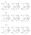
- the supply of increasing power can then be offered either by the actuator range structure presented in Figure 1, either by the actuator range structure presented at figure 2.
- the current motors continuous MDC11, MDC12 and MDC13 have the same rated voltage U1 and their nominal intensity is for example respectively I1, 1.5 x I1 and 2 x I1.
- the PS 10 converter used must be able to provide the most important of the three currents. It is therefore oversized in cases where it is used to power the MDC11 and MDC12 engines. This is all more economically penalizing than low power actuators generally correspond to the largest quantities requested by the market.
- a known solution to the previous problem is to use the range actuators shown in Figure 2.
- This range uses the same MDC21, MDC22 and MDC23 motors than those used in the range previous, respectively MDC11, MDC12 and MDC13.
- each PS21, PS22 and PS23 converter is respectively sized to provide, for example, under the same DC voltage U1, a rated current I1, 1.5 x I1 or 2 x I1.
- U1 DC voltage
- I1 1.5 x I1
- 2 x I1 1.5 x I1
- this solution is a problem. Indeed, it is necessary organize the manufacture of different converters. This results in a cost multiple reference management for the manufacturer and a dispersion of production volumes increasing the unit price of converters and therefore that of the actuators.
- a maneuvering device of a closure element comprises an electric motor DC powered by an AC-DC converter whose entrance is connected to the sector.
- the converter includes a means of adjusting the output voltage of the converter acting on a controlled switch. This means of adjusting the voltage supply allows the motor to run at different speeds to drive the closure element at different speeds.
- the object of the invention is to provide a range of actuators improving known actuator ranges and providing a solution to the problem supra.
- the invention makes it possible to reduce management costs and manufacturing the range of actuators.
- the range of electric actuators according to the invention is characterized by the characterizing part of claim 1.
- power components are usually grouped into two voltage classes, LV (low voltage) and TBT (very low voltage), and that within the TBT class, it is the intensity that dimension the components.
- LV low voltage
- TBT very low voltage
- a 60V transistor may indifferently work at voltages of 24 or 48 V, but it will choose different components depending on whether the rated current is 10 or 20 A.
- the method of producing a range of electric actuators according to the invention is characterized by the characterizing part of the claim 7.
- the method of producing an electric actuator according to the invention is characterized by the characterizing part of claim 8.
- the actuator according to the invention is produced according to the defined method previously.
- the invention also relates to an actuator of a range of actuators carried out according to the method defined above.
- the attached drawing represents, by way of example, two modes of embodiment of a range of actuators according to the invention.
- FIG. 1 is a diagram of a first range of actuators of different powers known from the prior art.
- FIG. 2 is a diagram of a second range of actuators of different powers known from the prior art.
- FIG. 3 is a diagram of a range of power actuators different according to the invention.
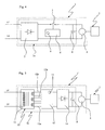
- FIG. 4 is a diagram of one of the actuators composing a range according to a first embodiment.
- FIG. 5 is a diagram of one of the actuators composing a range according to a second embodiment.
- the range shown in Figure 3 is composed of three actuators of respective powers PM, 1.5 x PM and 2 x PM.
- the converters 3 have the same structure and in particular the same power components. They provide, by simple modification or setting of a control circuit any of the three nominal voltages of the MDC31, MDC32 or MDC 33 motors. it is therefore not necessary to replace such a component that a transformer or a power transistor, influencing the sizing and the cost of such a converter.
- An actuator 1 according to a first embodiment is represented more in detail in Figure 4. This actuator is powered by the mains represented by the LP and LN neutral phase wires. It allows to operate a door 2.
- the actuator 1 comprises an AC / DC converter 3a and a DC motor 4.
- the converter is of the switching type.
- the mains voltage is rectified by a rectifying device 7 and is used to charge a capacitor 8 disposed between the terminals output of the converter 3a.
- the charge of capacitor 8 is controlled by a transistor 5 controlled by a control circuit 6.
- This control circuit includes a selector 9 for adjusting the voltage Release. The selector makes it possible to act on the conditions of blocking and turning on the transistor.
- the adjustment of the output voltage of the converter 3a can in particular be performed by manipulating a switch or moving a setting jumper.
- Any AC-DC converter may be suitable for implementation of the invention, provided that its structure allows a great dynamic output voltage without having to modify the components of its power circuit.
- the converter is of the "synchronous" type by sector.
- it contains a switch controlled at a frequency equal to once or twice the frequency sector.
- Such a converter is described in detail in the patent US 4,001,668 or pages 5-11 of the application WO 03/030344. These converters are characterized by a great dynamic in tension output or input voltage.
- a second embodiment of actuator 1 ' is shown in FIG. Figure 5. This actuator is powered by the sector represented by the wires LP phase and LN neutral. It allows to operate a door 2.
- the actuator 1 comprises an AC / DC converter 3b and a DC motor 4.
- the converter 3b is of type transformer and rectifier.
- the AC voltage of the sector is lowered by a transformer 10, then is rectified by a device rectifier 14 such as a diode bridge for charging a capacitor 8 disposed between the output terminals of the converter 3b.
- the transformer 10 comprises a carcass of material ferromagnetic around which are wound a primary winding 11 powered by the mains voltage and three secondary windings 12a, 12b and 12c. These windings can, thanks to means of connection 13, be connected in different configurations for supply the rectifier device under three different voltages. For change the output voltage of such a converter, just change the state of switches resulting in a different connection the different secondary windings between them.
- a selector 15 makes it possible to control the state of switches (no shown) in the connection means 13 to output the desired voltage.
- the different secondary windings may consist of coils of the same number of turns.
- three windings are selected coils of the same number of turns and connect one, two or three of these windings in parallel to the input of the rectifier to feed a 12V motor, two of these series windings are connected to the rectifier input to power a 24V motor and connect the three windings in series at the input of the rectifier to power a 36V motor.
- two secondary windings of number of different turns, giving respectively 12V and 24V voltages.
- the means of connection 13 then make it possible to select one of the two windings or carry out their serialization.
- the transformer may present several primary windings and a secondary winding.
- the different primary windings are then connected to the sector according to different configurations to obtain the desired output voltage.
- This variant has a disadvantage. Constraints of sizing require the realization of a transformer whose Empty energy consumption is important.
Landscapes
- Control Of Multiple Motors (AREA)
- Power-Operated Mechanisms For Wings (AREA)
Abstract
Description
L'invention se rapporte à une gamme d'actionneurs selon le préambule de la revendication 1. Elle concerne encore un procédé de réalisation d'une gamme d'actionneurs électriques, un procédé de réalisation d'un actionneur électrique et un actionneur réalisé selon ce procédé.The invention relates to a range of actuators according to the preamble of claim 1. It still relates to a method of making of a range of electric actuators, a method of producing a electric actuator and an actuator made according to this method.
Les portes équipant les bâtiments ou les portails présentent des dimensions variées et le choix des matériaux utilisés se répercute considérablement sur la masse et l'inertie des éléments mobiles et, par conséquent, sur les couples nécessaires à la manoeuvre de ceux-ci. Dans certains cas, il est prévu des dispositifs de compensation par contrepoids ou par ressorts.Doors fitted to buildings or gates have varied dimensions and the choice of materials used is reflected considerably on the mass and inertia of moving parts and, consequently, on the torques necessary to maneuver them. In some cases, compensation schemes are provided for counterweight or springs.
Les fabricants d'actionneurs permettant la manoeuvre automatique de telles portes sont le plus souvent confrontés à la nécessité de proposer une gamme d'actionneurs présentant des caractéristiques de puissance différentes, afin d'être en adéquation avec les caractéristiques de la porte ou du portail.Manufacturers of actuators allowing the automatic maneuvering of such doors are most often confronted with the need to propose a range of actuators with power characteristics different in order to match the characteristics of the door or portal.
Les actionneurs comprennent le plus souvent un moteur du type à courant continu qui est alimenté à partir du réseau alternatif par le biais d'un convertisseur alternatif continu. L'offre de puissance croissante peut alors être offerte soit par la structure de gamme d'actionneurs présentée à la figure 1, soit par la structure de gamme d'actionneurs présentée à la figure 2.The actuators most often comprise a motor of the type to DC current that is powered from the AC network through a continuous AC converter. The supply of increasing power can then be offered either by the actuator range structure presented in Figure 1, either by the actuator range structure presented at figure 2.
Dans le cas de la gamme représentée à la figure 1, les moteurs à courant continu MDC11, MDC12 et MDC13 présentent la même tension nominale U1 et leur intensité nominale vaut par exemple respectivement I1, 1.5 x I1 et 2 x I1. Ainsi, la puissance des différents moteurs vaut respectivement P1, 1.5 x P1 et 2 x P1, avec P1 = U1 x I1.In the case of the range represented in FIG. 1, the current motors continuous MDC11, MDC12 and MDC13 have the same rated voltage U1 and their nominal intensity is for example respectively I1, 1.5 x I1 and 2 x I1. Thus, the power of the different engines is worth respectively P1, 1.5 x P1 and 2 x P1, with P1 = U1 x I1.
Le convertisseur PS 10 utilisé doit être apte à fournir le plus important
des trois courants. Il est donc surdimensionné dans les cas où il est
utilisé pour alimenter les moteurs MDC11 et MDC12. Ceci est d'autant
plus pénalisant économiquement que les actionneurs de faible puissance
correspondent généralement aux plus grandes quantités demandées par
le marché.The
Une solution connue au problème précédent consiste, à utiliser la gamme d'actionneurs représentés à la figure 2. Cette gamme utilise les mêmes moteurs MDC21, MDC22 et MDC23 que ceux utilisés dans la gamme précédente, respectivement MDC11, MDC12 et MDC13. En revanche, chaque convertisseur PS21, PS22 et PS23, est respectivement dimensionné pour fournir, par exemple, sous une même tension continue U1, un courant nominal I1, 1.5 x I1 ou 2 x I1. Il existe ainsi une parfaite adéquation entre les différents convertisseurs PS21, PS22, PS23 et les moteurs. Cependant, cette solution pose un problème. En effet, il faut organiser la fabrication de différents convertisseurs. Il en résulte un coût de gestion de références multiples pour le fabricant et une dispersion des volumes de production renchérissant le prix unitaire des convertisseurs et donc celui des actionneurs.A known solution to the previous problem is to use the range actuators shown in Figure 2. This range uses the same MDC21, MDC22 and MDC23 motors than those used in the range previous, respectively MDC11, MDC12 and MDC13. On the other hand, each PS21, PS22 and PS23 converter is respectively sized to provide, for example, under the same DC voltage U1, a rated current I1, 1.5 x I1 or 2 x I1. There is thus a perfect between the different PS21, PS22, PS23 converters and the engines. However, this solution is a problem. Indeed, it is necessary organize the manufacture of different converters. This results in a cost multiple reference management for the manufacturer and a dispersion of production volumes increasing the unit price of converters and therefore that of the actuators.
Il est connu de la demande DE 195 47 965 un dispositif de manoeuvre d'un élément de fermeture. Ce dispositif comprend un moteur électrique à courant continu alimenté par un convertisseur de tension alternatif-continu dont l'entrée est reliée au secteur. Le convertisseur comprend un moyen de réglage de la tension de sortie du convertisseur agissant sur un interrupteur commandé. Ce moyen de réglage de la tension d'alimentation permet de faire tourner le moteur à différentes vitesses pour entraíner l'élément de fermeture à différentes vitesses.It is known from DE 195 47 965 a maneuvering device of a closure element. This device comprises an electric motor DC powered by an AC-DC converter whose entrance is connected to the sector. The converter includes a means of adjusting the output voltage of the converter acting on a controlled switch. This means of adjusting the voltage supply allows the motor to run at different speeds to drive the closure element at different speeds.
Dans le domaine éloigné de l'outillage électroportatif de bricolage, il est connu de la demande WO 01/69755 un dispositif de conversion de tension amovible destiné à permettre l'alimentation successive de plusieurs outils de différents types. Ce dispositif présente des moyens de réglage permettant d'adapter sa tension de sortie aux tensions nominales des outils. L'objet de cette demande est de fournir un dispositif permettant la suppression du filtre habituellement utilisé en sortie des convertisseurs alternatif-continu et ce dispositif est utilisé pour l'alimentation de moteurs universels.In the remote area of DIY power tools, it is known from the application WO 01/69755 a device for converting removable voltage intended to allow the successive feeding of several tools of different types. This device presents means of adjustment to adapt its output voltage to nominal voltages tools. The purpose of this application is to provide a device allowing the removal of the filter usually used at the output of AC-DC converters and this device is used to the supply of universal motors.
Le but de l'invention est de fournir une gamme d'actionneurs améliorant les gammes d'actionneur connues et apportant une solution au problème précité. En particulier, l'invention permet de réduire les coûts de gestion et de fabrication de la gamme d'actionneurs.The object of the invention is to provide a range of actuators improving known actuator ranges and providing a solution to the problem supra. In particular, the invention makes it possible to reduce management costs and manufacturing the range of actuators.
La gamme d'actionneurs électriques selon l'invention est caractérisée par la partie caractérisante de la revendication 1. Ces caractéristiques permettent au fabricant d'actionneurs d'utiliser le même modèle de convertisseur de tension pour réaliser toute une gamme d'actionneurs présentant des puissances variables. Ceci permet de faire baisser le prix de revient du modèle de convertisseur de tension utilisé (par une augmentation du volume de production) et de simplifier les procédures de fabrication des actionneurs (une même référence de convertisseur étant utilisée dans toute la gamme d'actionneurs).The range of electric actuators according to the invention is characterized by the characterizing part of claim 1. These features allow the actuator manufacturer to use the same model of voltage converter to realize a whole range of actuators with varying powers. This lowers the price of the voltage converter model used (by a increase in production volume) and to simplify the procedures for manufacture of the actuators (the same converter reference being used throughout the range of actuators).
Il faut noter que les composants de puissance sont généralement regroupés en deux classes de tension, BT (basse tension) et TBT (très basse tension), et qu'à l'intérieur de la classe TBT, c'est l'intensité qui dimensionne les composants. Par exemple, un transistor 60 V pourra indifféremment travailler à des tensions de 24 ou 48 V, mais il faudra choisir des composants différents selon que l'intensité nominale est 10 ou 20 A.It should be noted that power components are usually grouped into two voltage classes, LV (low voltage) and TBT (very low voltage), and that within the TBT class, it is the intensity that dimension the components. For example, a 60V transistor may indifferently work at voltages of 24 or 48 V, but it will choose different components depending on whether the rated current is 10 or 20 A.
Des variantes de réalisation de la gamme d'actionneurs selon l'invention
sont définies par les revendications dépendantes 2 à 6.Alternative embodiments of the range of actuators according to the invention
are defined by
Le procédé de réalisation d'une gamme d'actionneurs électriques selon
l'invention est caractérisé par la partie caractérisante de la revendication
7.The method of producing a range of electric actuators according to
the invention is characterized by the characterizing part of the
Le procédé de réalisation d'un actionneur électrique selon l'invention est
caractérisé par la partie caractérisante de la revendication 8.The method of producing an electric actuator according to the invention is
characterized by the characterizing part of
L'actionneur selon l'invention est réalisé selon le procédé défini précédemment.The actuator according to the invention is produced according to the defined method previously.
L'invention porte également sur un actionneur d'une gamme d'actionneurs réalisée selon le procédé défini précédemment.The invention also relates to an actuator of a range of actuators carried out according to the method defined above.
Le dessin annexé représente, à titre d'exemple, deux modes de réalisation d'une gamme d'actionneurs selon l'invention.The attached drawing represents, by way of example, two modes of embodiment of a range of actuators according to the invention.
La figure 1 est un schéma d'une première gamme d'actionneurs de puissances différentes connue de l'art antérieur.FIG. 1 is a diagram of a first range of actuators of different powers known from the prior art.
La figure 2 est un schéma d'une deuxième gamme d'actionneurs de puissances différentes connue de l'art antérieur. FIG. 2 is a diagram of a second range of actuators of different powers known from the prior art.
La figure 3 est un schéma d'une gamme d'actionneurs de puissances différentes selon l'invention.FIG. 3 is a diagram of a range of power actuators different according to the invention.
La figure 4 est un schéma d'un des actionneurs composant une gamme selon un premier mode de réalisation.FIG. 4 is a diagram of one of the actuators composing a range according to a first embodiment.
La figure 5 est un schéma d'un des actionneurs composant une gamme selon un deuxième mode de réalisation.FIG. 5 is a diagram of one of the actuators composing a range according to a second embodiment.
La gamme représentée à la figure 3 est composée de trois actionneurs de puissances respectives PM, 1.5 x PM et 2 x PM. Les moteurs utilisés MDC31, MDC32 et MDC33 présentent le même courant nominal I3, mais sont bobinés pour présenter des tensions nominales U3, 1.5 x U3, et 2 x U3, par exemple : 24, 36 et 48 volts avec U3 = 24 volts.The range shown in Figure 3 is composed of three actuators of respective powers PM, 1.5 x PM and 2 x PM. Engines used MDC31, MDC32 and MDC33 have the same rated current I3, but are wound to have nominal voltages U3, 1.5 x U3, and 2 x U3, for example: 24, 36 and 48 volts with U3 = 24 volts.
Les convertisseurs 3 présentent la même structure et en particulier les
mêmes composants de puissance. Ils fournissent, par simple
modification ou réglage d'un circuit de commande l'une ou l'autre des
trois tensions nominales des moteurs MDC31, MDC32 ou MDC 33. Il
n'est par conséquent pas nécessaire de remplacer de composant tel
qu'un transformateur ou un transistor de puissance, influençant le
dimensionnement et le coût d'un tel convertisseur.The
Un actionneur 1 selon un premier mode de réalisation est représenté plus
en détail à la figure 4. Cet actionneur est alimenté par le secteur
représenté par les fils de phase LP et de neutre LN. Il permet d'actionner
une porte 2.An actuator 1 according to a first embodiment is represented more
in detail in Figure 4. This actuator is powered by the mains
represented by the LP and LN neutral phase wires. It allows to operate
a
L'actionneur 1 comprend un convertisseur alternatif - continu 3a et un
moteur à courant continu 4. Le convertisseur est du type à découpage.
La tension du secteur est redressée par un dispositif de redressement 7
et est utilisée pour charger un condensateur 8 disposé entre les bornes
de sortie du convertisseur 3a. La charge du condensateur 8 est
commandée par un transistor 5 piloté par un circuit de commande 6. Ce
circuit de commande comprend un sélecteur 9 de réglage de la tension
de sortie. Le sélecteur permet d'agir sur les conditions de blocage et de
mise en conduction du transistor.The actuator 1 comprises an AC /
Le réglage de la tension de sortie du convertisseur 3a peut en particulier
être réalisée par manipulation d'un commutateur ou déplacement d'un
cavalier de réglage.The adjustment of the output voltage of the
Tout convertisseur alternatif - continu peut convenir à la mise en oeuvre de l'invention, pourvu que sa structure permette une grande dynamique de tension de sortie sans qu'il soit nécessaire de modifier les composants de son circuit de puissance.Any AC-DC converter may be suitable for implementation of the invention, provided that its structure allows a great dynamic output voltage without having to modify the components of its power circuit.
De manière préférée, le convertisseur est de type « synchrone » par rapport au secteur. On entend par-là qu'il contient un interrupteur commandé à une fréquence égale à une fois ou deux fois la fréquence du secteur. Un tel convertisseur est décrit en détail dans le brevet US 4,001,668 ou aux pages 5 à 11 de la demande WO 03/030344. Ces convertisseurs sont caractérisés par une grande dynamique en tension de sortie ou en tension d'entrée.Preferably, the converter is of the "synchronous" type by sector. We mean that it contains a switch controlled at a frequency equal to once or twice the frequency sector. Such a converter is described in detail in the patent US 4,001,668 or pages 5-11 of the application WO 03/030344. These converters are characterized by a great dynamic in tension output or input voltage.
Pour modifier la tension de sortie d'un tel convertisseur, il suffit d'ajuster ou modifier un ou plusieurs composants dans le circuit de commande. Cet ajustement ou modification ne concerne que des composants de bas niveau et est par conséquent pratiquement sans influence sur le coût du convertisseur. To change the output voltage of such a converter, simply adjust or modify one or more components in the control circuit. This adjustment or modification only concerns bottom components level and is therefore virtually without influence on the cost of the converter.
Un deuxième mode de réalisation d'actionneur 1' est représenté à la
figure 5. Cet actionneur est alimenté par le secteur représenté par les fils
de phase LP et de neutre LN. Il permet d'actionner une porte 2.A second embodiment of actuator 1 'is shown in FIG.
Figure 5. This actuator is powered by the sector represented by the wires
LP phase and LN neutral. It allows to operate a
L'actionneur 1' comprend un convertisseur alternatif - continu 3b et un
moteur à courant continu 4. Le convertisseur 3b est du type à
transformateur et redresseur. La tension alternative du secteur est
abaissée par un transformateur 10, puis est redressée par un dispositif
redresseur 14 tel qu'un pont de diodes pour charger un condensateur 8
disposé entre les bornes de sortie du convertisseur 3b.The actuator 1 'comprises an AC /
Le transformateur 10 comprend une carcasse en matériau
ferromagnétique autour de laquelle sont bobinés un enroulement primaire
11 alimenté par la tension du secteur et trois enroulements secondaires
12a, 12b et 12c. Ces enroulements peuvent, grâce à des moyens de
connexion 13, être branchés selon différentes configurations pour
alimenter le dispositif redresseur sous trois tensions différentes. Pour
modifier la tension de sortie d'un tel convertisseur, il suffit de modifier
l'état d'interrupteurs ayant pour conséquence de connecter différemment
les différents enroulements secondaires entre eux. A cet effet, un
sélecteur 15 permet de commander l'état d'interrupteurs (non
représentés) dans les moyens de connexion 13 pour obtenir en sortie la
tension désirée.The
Les différents enroulements secondaires peuvent être constitués par des bobinages de même nombre de spires.The different secondary windings may consist of coils of the same number of turns.
Par exemple dans le cas de l'utilisation d'un tel convertisseur pour
l'alimentation de moteurs 12V, 24V et 36V, on choisit trois enroulements
secondaires de même nombre de spires et on connecte un, deux ou trois
de ces enroulements en parallèle à l'entrée du redresseur pour alimenter
un moteur 12V, on connecte deux de ces enroulements en série à
l'entrée du redresseur pour alimenter un moteur 24V et on connecte les
trois enroulements en série à l'entrée du redresseur pour alimenter un
moteur 36V. Bien entendu, on peut aussi dans cet exemple choisir deux
enroulements secondaires de nombre de spires différents, donnant
respectivement des tensions de 12V et 24V. Les moyens de connexion
13 permettent alors de sélectionner l'un des deux enroulements ou de
réaliser leur mise en série.For example in the case of the use of such a converter for
12V, 24V and 36V motors supply, three windings are selected
coils of the same number of turns and connect one, two or three
of these windings in parallel to the input of the rectifier to feed
a 12V motor, two of these series windings are connected to
the rectifier input to power a 24V motor and connect the
three windings in series at the input of the rectifier to power a
36V motor. Of course, one can also in this example choose two
secondary windings of number of different turns, giving
respectively 12V and 24V voltages. The means of
Dans une variante de réalisation, le transformateur peut présenter plusieurs enroulements primaires et un enroulement secondaire. Les différents enroulements primaires sont alors connectés au secteur selon différentes configurations pour obtenir la tension de sortie désirée. Cette variante, présente cependant un inconvénient. Des contraintes de dimensionnement imposent la réalisation d'un transformateur dont la consommation énergétique à vide est importante.In an alternative embodiment, the transformer may present several primary windings and a secondary winding. The different primary windings are then connected to the sector according to different configurations to obtain the desired output voltage. This variant, however, has a disadvantage. Constraints of sizing require the realization of a transformer whose Empty energy consumption is important.
On notera que l'invention est décrite dans le cas d'actionneurs pour portes de garage ou portails mais elle peut être appliquée de même à des actionneurs destinés à la manoeuvre d'autres équipements tels que des volets roulants ou des stores.Note that the invention is described in the case of actuators for garage doors or gates but it can be applied similarly to actuators for the operation of other equipment such as shutters or blinds.
Claims (9)
Applications Claiming Priority (4)
| Application Number | Priority Date | Filing Date | Title |
|---|---|---|---|
| FR0315065 | 2003-12-19 | ||
| FR0315065A FR2864365A1 (en) | 2003-12-19 | 2003-12-19 | Electric actuator assembly for actuating e.g. garage door, has three electric actuators, each with DC motor and AC/DC converter that has power circuit and control circuit with selector for adjusting output voltage of converter |
| FR0401227 | 2004-02-09 | ||
| FR0401227A FR2864366B1 (en) | 2003-12-19 | 2004-02-09 | RANGE OF ELECTRIC ACTUATORS FOR DOORS AND METHOD FOR PRODUCING THE RANGE |
Publications (2)
| Publication Number | Publication Date |
|---|---|
| EP1544993A2 true EP1544993A2 (en) | 2005-06-22 |
| EP1544993A3 EP1544993A3 (en) | 2005-11-16 |
Family
ID=34525007
Family Applications (1)
| Application Number | Title | Priority Date | Filing Date |
|---|---|---|---|
| EP04029789A Withdrawn EP1544993A3 (en) | 2003-12-19 | 2004-12-16 | Sieries of electric door actuators and process of their realization |
Country Status (3)
| Country | Link |
|---|---|
| EP (1) | EP1544993A3 (en) |
| ES (1) | ES2239941T1 (en) |
| FR (1) | FR2864366B1 (en) |
Citations (1)
| Publication number | Priority date | Publication date | Assignee | Title |
|---|---|---|---|---|
| EP0862810B1 (en) * | 1995-11-24 | 2001-10-10 | Siemens Aktiengesellschaft | Drive unit for an electric door |
Family Cites Families (5)
| Publication number | Priority date | Publication date | Assignee | Title |
|---|---|---|---|---|
| DE19547965A1 (en) * | 1995-12-21 | 1997-06-26 | Hoermann Kg Verkaufsges | Power supply device for a direct current motor drive unit, in particular with detection of distance-dependent parameters of the driven object |
| DE19728644A1 (en) * | 1997-07-04 | 1999-01-21 | Bosch Gmbh Robert | Electric drive, in particular for a garage door, with a DC motor |
| US6286609B1 (en) * | 1999-12-10 | 2001-09-11 | Black & Decker Inc. | AC/DC chopper for power tool |
| US20020075711A1 (en) * | 2000-10-24 | 2002-06-20 | Bel-Fuse, Inc. | Split-package AC adapter |
| FR2827095B1 (en) * | 2001-07-06 | 2003-10-24 | Fabrice Barthelemy | VOLTAGE CONVERTER CAPABLE OF SUPPLYING SEVERAL LOW CONTINUOUS SAFETY VOLTAGES |
-
2004
- 2004-02-09 FR FR0401227A patent/FR2864366B1/en not_active Expired - Fee Related
- 2004-12-16 ES ES04029789T patent/ES2239941T1/en active Pending
- 2004-12-16 EP EP04029789A patent/EP1544993A3/en not_active Withdrawn
Patent Citations (1)
| Publication number | Priority date | Publication date | Assignee | Title |
|---|---|---|---|---|
| EP0862810B1 (en) * | 1995-11-24 | 2001-10-10 | Siemens Aktiengesellschaft | Drive unit for an electric door |
Also Published As
| Publication number | Publication date |
|---|---|
| FR2864366A1 (en) | 2005-06-24 |
| ES2239941T1 (en) | 2005-10-16 |
| EP1544993A3 (en) | 2005-11-16 |
| FR2864366B1 (en) | 2006-04-14 |
Similar Documents
| Publication | Publication Date | Title |
|---|---|---|
| EP0605328B2 (en) | Optimal power supply for electric motor | |
| EP2908412B1 (en) | Electromechanical actuator comprising an electric motor, installation comprising such an actuator, range of actuators and related manufacturing method | |
| EP2842223A2 (en) | Method of controlling charge of a battery | |
| EP3363111A1 (en) | Insulated dc/dc converter | |
| EP4136308B1 (en) | Device for driving a closure or shading member in a building by means of a solar energy source | |
| EP1544993A2 (en) | Sieries of electric door actuators and process of their realization | |
| EP1820258B1 (en) | Method for feeding an operating motor of a rolling shutter and a device for a driven rolling shutter | |
| EP1738456A1 (en) | Electrical installation for supplying an actuator equipped with a back-up device | |
| FR2864365A1 (en) | Electric actuator assembly for actuating e.g. garage door, has three electric actuators, each with DC motor and AC/DC converter that has power circuit and control circuit with selector for adjusting output voltage of converter | |
| EP1918506B1 (en) | Home automation actuator comprising an asynchronous electric motor with variable rotation speed | |
| EP1230726B1 (en) | Air conditioning valve actuator for motor vehicle | |
| EP2380267B1 (en) | Dc to dc voltage converter comprising a charge pump capacitor | |
| FR2692418A1 (en) | Motorised venetian blind electrical supply system - in which each blind has its own battery and drive motor connected to common supply | |
| EP1772303A1 (en) | Method and system for switching on a supply bus of an electric vehicle, storage medium and vehicle for carrying out the method | |
| FR2911735A1 (en) | METHOD FOR SUPPLYING A SINGLE PHASE ELECTRIC MOTOR AND FEEDING SYSTEM FOR IMPLEMENTING SUCH A METHOD | |
| EP3910780A1 (en) | Electric power supply device, electromechanical actuator comprising such a power supply device and closing, concealing or sun-protection system including such an electromechanical actuator | |
| EP0096642B1 (en) | Power supply switching converter | |
| EP2528224B1 (en) | Device for controlling a motor for roller shutter useable with or without mains supply neutral | |
| FR2820560A1 (en) | FEEDING DEVICE | |
| CA3218959A1 (en) | Rechargeable battery | |
| EP3121366A1 (en) | Detection method for the moving direction of a concealing screen | |
| FR3160525A1 (en) | SYNCHRONOUS RECTIFICATION METHOD AND BATTERY CHARGER EMPLOYING SUCH A METHOD | |
| EP3121365B1 (en) | Detection method for the moving direction of a concealing screen | |
| FR2827095A1 (en) | Low voltage DC power supply includes transformer with single secondary producing range of voltages by control of primary conduction times | |
| FR2874465A1 (en) | METHOD AND DISPOSITION OF SUPPLYING A DC MOTOR FOR CONTINUOUS CURRENT USE FOR DRIVING A ROLLING SHUTTER |
Legal Events
| Date | Code | Title | Description |
|---|---|---|---|
| PUAI | Public reference made under article 153(3) epc to a published international application that has entered the european phase |
Free format text: ORIGINAL CODE: 0009012 |
|
| AK | Designated contracting states |
Kind code of ref document: A2 Designated state(s): AT BE BG CH CY CZ DE DK EE ES FI FR GB GR HU IE IS IT LI LT LU MC NL PL PT RO SE SI SK TR |
|
| AX | Request for extension of the european patent |
Extension state: AL BA HR LV MK YU |
|
| PUAL | Search report despatched |
Free format text: ORIGINAL CODE: 0009013 |
|
| AK | Designated contracting states |
Kind code of ref document: A3 Designated state(s): AT BE BG CH CY CZ DE DK EE ES FI FR GB GR HU IE IS IT LI LT LU MC NL PL PT RO SE SI SK TR |
|
| AX | Request for extension of the european patent |
Extension state: AL BA HR LV MK YU |
|
| 17P | Request for examination filed |
Effective date: 20060327 |
|
| AKX | Designation fees paid |
Designated state(s): AT BE BG CH CY CZ DE DK EE ES FI FR GB GR HU IE IS IT LI LT LU MC NL PL PT RO SE SI SK TR |
|
| 17Q | First examination report despatched |
Effective date: 20110321 |
|
| 18D | Application deemed to be withdrawn |
Effective date: 20110802 |
|
| STAA | Information on the status of an ep patent application or granted ep patent |
Free format text: STATUS: THE APPLICATION IS DEEMED TO BE WITHDRAWN |
|
| R18D | Application deemed to be withdrawn (corrected) |
Effective date: 20110701 |