EP1544932A2 - Electrolyte support member for high differential pressure electrochemical cell - Google Patents
Electrolyte support member for high differential pressure electrochemical cell Download PDFInfo
- Publication number
- EP1544932A2 EP1544932A2 EP04257868A EP04257868A EP1544932A2 EP 1544932 A2 EP1544932 A2 EP 1544932A2 EP 04257868 A EP04257868 A EP 04257868A EP 04257868 A EP04257868 A EP 04257868A EP 1544932 A2 EP1544932 A2 EP 1544932A2
- Authority
- EP
- European Patent Office
- Prior art keywords
- recesses
- support member
- lattice pattern
- flow passages
- patterns
- Prior art date
- Legal status (The legal status is an assumption and is not a legal conclusion. Google has not performed a legal analysis and makes no representation as to the accuracy of the status listed.)
- Granted
Links
- 239000003792 electrolyte Substances 0.000 title description 8
- 239000000463 material Substances 0.000 claims abstract description 46
- 239000012528 membrane Substances 0.000 claims abstract description 27
- 238000000034 method Methods 0.000 claims description 10
- 238000005530 etching Methods 0.000 claims description 4
- 238000004519 manufacturing process Methods 0.000 claims description 4
- 238000005266 casting Methods 0.000 claims description 2
- 238000000465 moulding Methods 0.000 claims 1
- 239000007787 solid Substances 0.000 abstract description 5
- 239000003014 ion exchange membrane Substances 0.000 abstract description 4
- 239000005518 polymer electrolyte Substances 0.000 abstract description 4
- 238000003486 chemical etching Methods 0.000 abstract 1
- 230000008901 benefit Effects 0.000 description 8
- 239000012530 fluid Substances 0.000 description 8
- 239000002184 metal Substances 0.000 description 8
- 238000005516 engineering process Methods 0.000 description 4
- 239000000446 fuel Substances 0.000 description 4
- 238000013461 design Methods 0.000 description 3
- 239000011888 foil Substances 0.000 description 3
- UFHFLCQGNIYNRP-UHFFFAOYSA-N Hydrogen Chemical compound [H][H] UFHFLCQGNIYNRP-UHFFFAOYSA-N 0.000 description 2
- MHAJPDPJQMAIIY-UHFFFAOYSA-N Hydrogen peroxide Chemical compound OO MHAJPDPJQMAIIY-UHFFFAOYSA-N 0.000 description 2
- 230000000712 assembly Effects 0.000 description 2
- 238000000429 assembly Methods 0.000 description 2
- 238000003860 storage Methods 0.000 description 2
- 239000000758 substrate Substances 0.000 description 2
- XLYOFNOQVPJJNP-UHFFFAOYSA-N water Substances O XLYOFNOQVPJJNP-UHFFFAOYSA-N 0.000 description 2
- 239000012670 alkaline solution Substances 0.000 description 1
- 238000013459 approach Methods 0.000 description 1
- 239000002131 composite material Substances 0.000 description 1
- 238000010276 construction Methods 0.000 description 1
- 238000005868 electrolysis reaction Methods 0.000 description 1
- 239000001257 hydrogen Substances 0.000 description 1
- 229910052739 hydrogen Inorganic materials 0.000 description 1
- 238000001746 injection moulding Methods 0.000 description 1
- 238000005342 ion exchange Methods 0.000 description 1
- 239000011244 liquid electrolyte Substances 0.000 description 1
- 239000011159 matrix material Substances 0.000 description 1
- 238000012986 modification Methods 0.000 description 1
- 230000004048 modification Effects 0.000 description 1
- 229920000642 polymer Polymers 0.000 description 1
- 230000002028 premature Effects 0.000 description 1
- 238000012545 processing Methods 0.000 description 1
- 230000002787 reinforcement Effects 0.000 description 1
- 239000003566 sealing material Substances 0.000 description 1
- 238000004513 sizing Methods 0.000 description 1
- 239000007921 spray Substances 0.000 description 1
- 238000012360 testing method Methods 0.000 description 1
- 230000036962 time dependent Effects 0.000 description 1
- 230000007704 transition Effects 0.000 description 1
Images

Classifications
-
- H—ELECTRICITY
- H01—ELECTRIC ELEMENTS
- H01M—PROCESSES OR MEANS, e.g. BATTERIES, FOR THE DIRECT CONVERSION OF CHEMICAL ENERGY INTO ELECTRICAL ENERGY
- H01M8/00—Fuel cells; Manufacture thereof
- H01M8/02—Details
- H01M8/0202—Collectors; Separators, e.g. bipolar separators; Interconnectors
- H01M8/0247—Collectors; Separators, e.g. bipolar separators; Interconnectors characterised by the form
-
- C—CHEMISTRY; METALLURGY
- C25—ELECTROLYTIC OR ELECTROPHORETIC PROCESSES; APPARATUS THEREFOR
- C25B—ELECTROLYTIC OR ELECTROPHORETIC PROCESSES FOR THE PRODUCTION OF COMPOUNDS OR NON-METALS; APPARATUS THEREFOR
- C25B13/00—Diaphragms; Spacing elements
- C25B13/02—Diaphragms; Spacing elements characterised by shape or form
-
- H—ELECTRICITY
- H01—ELECTRIC ELEMENTS
- H01M—PROCESSES OR MEANS, e.g. BATTERIES, FOR THE DIRECT CONVERSION OF CHEMICAL ENERGY INTO ELECTRICAL ENERGY
- H01M4/00—Electrodes
- H01M4/86—Inert electrodes with catalytic activity, e.g. for fuel cells
- H01M4/8605—Porous electrodes
- H01M4/8626—Porous electrodes characterised by the form
-
- H—ELECTRICITY
- H01—ELECTRIC ELEMENTS
- H01M—PROCESSES OR MEANS, e.g. BATTERIES, FOR THE DIRECT CONVERSION OF CHEMICAL ENERGY INTO ELECTRICAL ENERGY
- H01M8/00—Fuel cells; Manufacture thereof
- H01M8/02—Details
- H01M8/0202—Collectors; Separators, e.g. bipolar separators; Interconnectors
- H01M8/0258—Collectors; Separators, e.g. bipolar separators; Interconnectors characterised by the configuration of channels, e.g. by the flow field of the reactant or coolant
- H01M8/0265—Collectors; Separators, e.g. bipolar separators; Interconnectors characterised by the configuration of channels, e.g. by the flow field of the reactant or coolant the reactant or coolant channels having varying cross sections
-
- H—ELECTRICITY
- H01—ELECTRIC ELEMENTS
- H01M—PROCESSES OR MEANS, e.g. BATTERIES, FOR THE DIRECT CONVERSION OF CHEMICAL ENERGY INTO ELECTRICAL ENERGY
- H01M8/00—Fuel cells; Manufacture thereof
- H01M8/02—Details
- H01M8/0271—Sealing or supporting means around electrodes, matrices or membranes
-
- H—ELECTRICITY
- H01—ELECTRIC ELEMENTS
- H01M—PROCESSES OR MEANS, e.g. BATTERIES, FOR THE DIRECT CONVERSION OF CHEMICAL ENERGY INTO ELECTRICAL ENERGY
- H01M8/00—Fuel cells; Manufacture thereof
- H01M8/02—Details
- H01M8/0289—Means for holding the electrolyte
-
- H—ELECTRICITY
- H01—ELECTRIC ELEMENTS
- H01M—PROCESSES OR MEANS, e.g. BATTERIES, FOR THE DIRECT CONVERSION OF CHEMICAL ENERGY INTO ELECTRICAL ENERGY
- H01M8/00—Fuel cells; Manufacture thereof
- H01M8/10—Fuel cells with solid electrolytes
- H01M2008/1095—Fuel cells with polymeric electrolytes
-
- H—ELECTRICITY
- H01—ELECTRIC ELEMENTS
- H01M—PROCESSES OR MEANS, e.g. BATTERIES, FOR THE DIRECT CONVERSION OF CHEMICAL ENERGY INTO ELECTRICAL ENERGY
- H01M8/00—Fuel cells; Manufacture thereof
- H01M8/10—Fuel cells with solid electrolytes
- H01M8/1004—Fuel cells with solid electrolytes characterised by membrane-electrode assemblies [MEA]
-
- Y—GENERAL TAGGING OF NEW TECHNOLOGICAL DEVELOPMENTS; GENERAL TAGGING OF CROSS-SECTIONAL TECHNOLOGIES SPANNING OVER SEVERAL SECTIONS OF THE IPC; TECHNICAL SUBJECTS COVERED BY FORMER USPC CROSS-REFERENCE ART COLLECTIONS [XRACs] AND DIGESTS
- Y02—TECHNOLOGIES OR APPLICATIONS FOR MITIGATION OR ADAPTATION AGAINST CLIMATE CHANGE
- Y02E—REDUCTION OF GREENHOUSE GAS [GHG] EMISSIONS, RELATED TO ENERGY GENERATION, TRANSMISSION OR DISTRIBUTION
- Y02E60/00—Enabling technologies; Technologies with a potential or indirect contribution to GHG emissions mitigation
- Y02E60/30—Hydrogen technology
- Y02E60/50—Fuel cells
-
- Y—GENERAL TAGGING OF NEW TECHNOLOGICAL DEVELOPMENTS; GENERAL TAGGING OF CROSS-SECTIONAL TECHNOLOGIES SPANNING OVER SEVERAL SECTIONS OF THE IPC; TECHNICAL SUBJECTS COVERED BY FORMER USPC CROSS-REFERENCE ART COLLECTIONS [XRACs] AND DIGESTS
- Y02—TECHNOLOGIES OR APPLICATIONS FOR MITIGATION OR ADAPTATION AGAINST CLIMATE CHANGE
- Y02P—CLIMATE CHANGE MITIGATION TECHNOLOGIES IN THE PRODUCTION OR PROCESSING OF GOODS
- Y02P70/00—Climate change mitigation technologies in the production process for final industrial or consumer products
- Y02P70/50—Manufacturing or production processes characterised by the final manufactured product
-
- Y—GENERAL TAGGING OF NEW TECHNOLOGICAL DEVELOPMENTS; GENERAL TAGGING OF CROSS-SECTIONAL TECHNOLOGIES SPANNING OVER SEVERAL SECTIONS OF THE IPC; TECHNICAL SUBJECTS COVERED BY FORMER USPC CROSS-REFERENCE ART COLLECTIONS [XRACs] AND DIGESTS
- Y10—TECHNICAL SUBJECTS COVERED BY FORMER USPC
- Y10T—TECHNICAL SUBJECTS COVERED BY FORMER US CLASSIFICATION
- Y10T29/00—Metal working
- Y10T29/49—Method of mechanical manufacture
- Y10T29/49995—Shaping one-piece blank by removing material
- Y10T29/49996—Successive distinct removal operations
Definitions
- This invention generally relates to supporting ion exchange membranes such as those used in proton exchange membrane hydrogen generators by water electrolysis and fuel cell technology. More particularly, this invention relates to a single piece support member for such applications, for example.
- Solid polymer electrolyte technology is a suitable option for high-pressure applications because the electrolyte is a flexible solid and has a higher differential pressure capability than the bubble pressure of the typical electrolyte matrix structure used to contain liquid electrolyte.
- High-pressure hardware further enables elevated pressure to be used on both sides of the cell or only on the fluid-side of the system where it is required for storage, while the balance of the system remains at essentially ambient pressure.
- the ion exchange electrolyte membrane is also the sealing material and the only separator between the anode and cathode cavities of the cell assembly.
- the electrodes are typically applied directly to the polymer sheet and the electrical contact is established through a permeable member to allow, as much as possible, unobstructed material exchange between electrodes and the fluid cavities.
- the fluid cavities are designed in a known manner to contain the pressure and keep the fluids separated as required for the cell operation.
- the hardware of a typical high-pressure cell is made mostly of metal.
- the electrolyte membrane is typically the weakest component in the cell assembly.
- Typical membrane materials are not altered or substituted to match strength to the stress expected in the application. Instead, the support for the electrolyte membrane is typically tailored to provide adequate reinforcement against a differential loading expected for a particular application. Additionally, providing adequate membrane support is complicated because the membrane material typically creeps even at lower stress levels. The membrane is inherently weaker than the other materials in the assembly so support is necessary and sizing for creep renders the design task even more difficult. Creep is known to be a time-dependent phenomenon, which is not under a designer's control. In most situations, the membrane will deform to the point of failure and the only question seems to be how long it will take until failure occurs.
- a supported membrane which appears to perform adequately in a testing situation, may still fail after a longer duration or if the assembly were put into full service.
- the support has to provide the strength as well as to limit the movement due to creep without hindering the fluid interchange or add unreasonable weight or expense to the assembly.
- this invention is a single-piece membrane support member.
- One application for an example embodiment is for a high pressure electrochemical cell having a built-in limit for the membrane movement due to material creep when operating under stress at elevated temperature, pressure or both.
- a support member comprises a monolithic body having a first side with a plurality of first recesses arranged in a first pattern.
- a second side has a plurality of second recesses arranged in a second pattern.
- the first and second patterns are arranged relative to each other such that a plurality of flow passages across the body are defined by overlapping portions of the first and second recesses.
- the single-piece structure maintains the recesses in a fixed relationship, which ensures adequate flow and provides enhanced strength superior to the multi-layered arrangements.
- an ion exchange membrane support member includes a single piece of material having a first lattice pattern on a first side and a second lattice pattern on a second side.
- the first and second lattice patterns are asymmetric and together establish a plurality of flow passages through the piece of material.
- One example method of making an exchange membrane support member includes forming a first lattice pattern on a first side of a single piece of material. Forming a second lattice pattern that is asymmetric relative to the first lattice pattern on a second side of the piece of material provides flow passages through the material.
- the first and second sides are simultaneously etched to establish the respective lattice patterns and the flow passages.
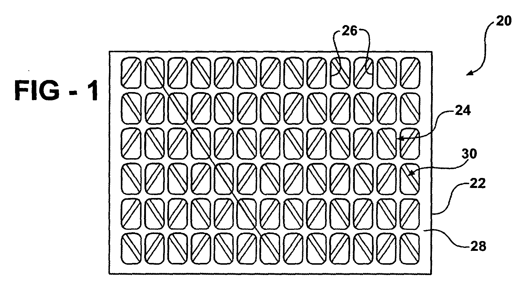
- Figure 1 schematically shows a membrane support member 20.
- a single piece of material 22 has a first lattice pattern 24 with a plurality of recesses 26 on a first side 28 of the material.
- a second lattice pattern 30 on a second side 32 of the single piece of material includes a plurality of recesses 34.
- the lattice patterns 24 and 30 are asymmetric relative to each other.
- the lattice pattern 24 includes a plurality of generally rectangular recesses 26.
- the lattice pattern 30 in this example includes a plurality of generally diamond-shaped recesses 34.
- lattice patterns Although specific lattice patterns are shown, a variety of patterns may be used to meet the needs of a particular situation. Those skilled in the art who have the benefit of this description will be able to select appropriate geometries of the recesses and lattice patterns to meet the needs of their particular situation.
- each set of recesses on each side of the sheet of material 22 each have a depth that is less than the overall thickness of the piece of material 22.
- each set of recesses has a depth that corresponds to approximately one-half of the thickness of material.
- one set of recesses has a depth that is greater than the other set of recesses.
- Overlapping portions of the recesses 26 and the recesses 34 establish flow passages through the material 22. Because the combined depths of the recesses equals the thickness of the material in this example, overlapping portions of the recesses provide openings through the material, which serve as the flow passages.
- the example flow passages allow fluid flow perpendicular to the plane of the support member 20 and within the plane of the support member 20.
- the single-piece construction ensures that the alignment of recesses remains fixed and the flow passages do not become blocked as may otherwise occur if discrete sheets of support mesh were used.
- the single piece of material 22 having first and second lattice patterns 24 and 30 provides a stronger structure than previous two-layer assemblies because the two lattice patterns are part of the same sheet of material.
- the composite stiffness is increased compared to distinct layer assemblies.
- the attached nature of the lattices which is a feature of the single-piece structure, allows one lattice to support the other and to resist deformations.
- One example support member designed according to the embodiments of Figures 1 and 2 is able to withstand pressures on the order of approximately 5,517 kPa (800 PSI) without any corresponding membrane failure.
- the monolithic support member has a continuous transition between the active and seal areas of the cell assembly hardware.
- the single-piece design greatly reduces or eliminates any differential movement that occurred when a prior art sintered porous metal plate was used for membrane support because the prior art approach creates a discontinuity in the metal foil between the active and seal areas of the cell hardware.
- Such a discontinuity creates two areas of differential movement or compressive stiffness in the hardware because the compressive force required on the seal is different from that in the active area.
- the differential movement is greatly reduced or eliminated. This feature is advantageous to protect the electrolyte membrane from hardware-induced stresses and premature cell failure.
- FIG. 3 schematically shows a solid polymer electrolyte electrochemical cell assembly 40 having known fluid cavities 42 and 44.
- the assembly includes an example support member 20 designed according to an embodiment of this invention.
- the support members 20 are positioned on opposite sides of electrodes 50a and 50b and the electrolyte membrane 52.
- Conventional terminating separators 54 establish the outside of the fluid cavities 42 and 44, which serve as the anode and cathode of a fuel cell assembly in one example.
- the components used to make such a cell assembly are known and utilizing an ion exchange membrane support member 20 designed according to this invention provides several advantages.
- the support member a variety of materials may be used to form the support member.
- injection molding forms the support member having the first and second lattice patterns on opposite sides of the single piece of material.
- a casting technique is used to form the support member.
- conventional etching techniques are used to establish the lattice patterns on the sides of the single piece of material 22.
- One example includes using a print image on a transparent substrate darkened with the areas to be etched.
- a metal foil is then coated with a modified rubber film according to the transparent substrate.
- Photo tools are then aligned on both sides of the piece of material and exposed to light.
- the rubber film is cured and the portions coated with the rubber film are protected from etching.
- the foil material is then put into a conventional etching process where it is heated and jets of etchants are applied to each side of the material. The speed with which the material moves through the processing machinery and the amount of spray applied controls the depth of the recesses formed on the respective sides.
- an alkaline solution removes the cured rubber film and the resulting support member can be handled in a conventional manner and used in the desired application.
- an etched support member designed according to this invention provides significant cost savings compared to sintered porous metal plates of comparable size. In one example, the cost savings were on the order of 50%.
- a variety of materials may be required for electrochemical hardware and material selection is important for device performance and useful life.
- Using an etched support member designed according to this invention allows for manufacturing the support member from a wide variety of materials.
- a support member designed according to an embodiment of this invention may be used for a variety of applications that require high operating pressure and which would benefit from having high differential pressure capability built into the hardware. Example applications extend beyond fuel cell technology and include electrochemical compressors and separators, electrochemical reactors for hydrogen peroxide production and similar applications. Those skilled in the art who have the benefit of this description will realize what situations with which they are presented will benefit from using a support member designed according to this invention.
Landscapes
- Chemical & Material Sciences (AREA)
- Chemical Kinetics & Catalysis (AREA)
- Electrochemistry (AREA)
- General Chemical & Material Sciences (AREA)
- Engineering & Computer Science (AREA)
- Manufacturing & Machinery (AREA)
- Life Sciences & Earth Sciences (AREA)
- Sustainable Development (AREA)
- Sustainable Energy (AREA)
- Metallurgy (AREA)
- Organic Chemistry (AREA)
- Materials Engineering (AREA)
- Fuel Cell (AREA)
- Electrolytic Production Of Non-Metals, Compounds, Apparatuses Therefor (AREA)
- Separation Using Semi-Permeable Membranes (AREA)
Abstract
Description
Claims (16)
- A membrane support member (20), comprising:a monolithic body (22) having a first side (28) with a plurality of first recesses (26) arranged in a first pattern (24) and a second side (32) with a plurality of second recesses (34) arranged in a second pattern (30), the first and second patterns (24, 30) being arranged relative to each other such that a plurality of flow passages across the body (22) are defined by overlapping portions of the first and second recesses (26, 34).
- The support member of claim 1, wherein the first and second patterns (24, 30) are asymmetric with respect to each other.
- A membrane support member (20) , comprising:a single piece (22) of material having a first lattice pattern (24) on a first side (28) and a second lattice pattern (30) on a second side (32), the first and second lattice patterns (24, 30) being asymmetric and together establishing a plurality of flow passages through the piece (22) of material.
- The member of claim 3, wherein the first lattice pattern (24) defines a plurality of first recesses (26), the second lattice pattern (30) defines a plurality of second recesses (34) and the plurality of flow passages are defined by overlapping portions of the first and second recesses (26, 34).
- The support member of claim 1, 2 or 4 wherein the body or piece (22) has a thickness, the first recesses (26) have a first depth, the second recesses (34) have a second depth and the first and second depths together are approximately equal to the thickness.
- The support member of claim 1, 2, 4 or 5 wherein the flow passages are smaller than the first or the second recesses (26, 34).
- The support member of any preceding claim, wherein the first pattern (24) defines a first geometry and the second pattern (30) defines a second geometry.
- The support member of claim 7, wherein the first and second geometries are different.
- The support member of claim 7 or 8, wherein the flow passages have a third geometry.
- A method of making an exchange membrane support member (20), comprising:forming a first lattice pattern (24) on a first side (28) of a single piece (22) of material; andforming a second lattice pattern (30) that is asymmetric relative to the first lattice pattern (24) on a second side (32) of the single piece (22) of material to provide flow passages through the material.
- The method of claim 10, including etching the patterns (24, 30).
- The method of claim 10, including forming the patterns (24, 30) during one of a molding or a casting process.
- The method of claim 10, 11 or 12, including forming a plurality of first recesses (26) in a first side (28) of the material and a plurality of second recesses (34) arranged in a second side (32) of the material and arranging the first and second patterns (24. 30) relative to each other such that the plurality of flow passages are defined by overlapping portions of the first and second recesses (26, 34).
- The method of claim 13, including forming the first recesses (26) with a first geometry and the second recesses (34) with a second geometry.
- The method of claim 14, wherein the first and second geometries are different.
- The method of claim 13, 14 or 15, including providing the first recesses (26) with a first depth, the second recesses (34) with a second depth and selecting the first and second depths such that the first and second depths together are approximately equal to a thickness of the material.
Applications Claiming Priority (2)
| Application Number | Priority Date | Filing Date | Title |
|---|---|---|---|
| US739650 | 2003-12-18 | ||
| US10/739,650 US7217472B2 (en) | 2003-12-18 | 2003-12-18 | Electrolyte support member for high differential pressure electrochemical cell |
Publications (3)
| Publication Number | Publication Date |
|---|---|
| EP1544932A2 true EP1544932A2 (en) | 2005-06-22 |
| EP1544932A3 EP1544932A3 (en) | 2007-09-12 |
| EP1544932B1 EP1544932B1 (en) | 2010-10-06 |
Family
ID=34523191
Family Applications (1)
| Application Number | Title | Priority Date | Filing Date |
|---|---|---|---|
| EP04257868A Expired - Lifetime EP1544932B1 (en) | 2003-12-18 | 2004-12-16 | Electrolyte support member for high differential pressure electrochemical cell |
Country Status (4)
| Country | Link |
|---|---|
| US (1) | US7217472B2 (en) |
| EP (1) | EP1544932B1 (en) |
| JP (1) | JP4733380B2 (en) |
| DE (1) | DE602004029437D1 (en) |
Cited By (2)
| Publication number | Priority date | Publication date | Assignee | Title |
|---|---|---|---|---|
| US7847184B2 (en) | 2006-07-28 | 2010-12-07 | E. I. Du Pont De Nemours And Company | Low modulus solar cell encapsulant sheets with enhanced stability and adhesion |
| EP2362005A1 (en) * | 2010-02-15 | 2011-08-31 | Hamilton Sundstrand Corporation | High-differential-pressure water electrolysis cell and method of operation |
Families Citing this family (15)
| Publication number | Priority date | Publication date | Assignee | Title |
|---|---|---|---|---|
| US7935456B2 (en) * | 2005-09-13 | 2011-05-03 | Andrei Leonida | Fluid conduit for an electrochemical cell and method of assembling the same |
| US8008574B2 (en) * | 2008-06-03 | 2011-08-30 | Hamilton Sundstrand Corporation | Photo cell with spaced anti-oxidation member on fluid loop |
| US8177884B2 (en) * | 2009-05-20 | 2012-05-15 | United Technologies Corporation | Fuel deoxygenator with porous support plate |
| US8015830B2 (en) * | 2009-08-20 | 2011-09-13 | Hamilton Sundstrand Space Systems International, Inc. | Heat pump for high temperature environments |
| GB201017346D0 (en) * | 2010-10-14 | 2010-11-24 | Advanced Oxidation Ltd | A bipolar cell for a reactor for treatment of waste water and effluent |
| US9017528B2 (en) * | 2011-04-14 | 2015-04-28 | Tel Nexx, Inc. | Electro chemical deposition and replenishment apparatus |
| US9005409B2 (en) * | 2011-04-14 | 2015-04-14 | Tel Nexx, Inc. | Electro chemical deposition and replenishment apparatus |
| JP6090790B2 (en) * | 2013-11-05 | 2017-03-08 | 本田技研工業株式会社 | Differential pressure type high pressure water electrolyzer |
| US9303329B2 (en) | 2013-11-11 | 2016-04-05 | Tel Nexx, Inc. | Electrochemical deposition apparatus with remote catholyte fluid management |
| US20170362718A1 (en) | 2016-06-16 | 2017-12-21 | Panasonic Intellectual Property Management Co., Ltd. | Gas diffusion layer and electrochemical hydrogen pump |
| JP2018059181A (en) | 2016-10-05 | 2018-04-12 | パナソニックIpマネジメント株式会社 | Gas diffusion device and electrochemical hydrogen pump |
| JP2018062707A (en) | 2016-10-07 | 2018-04-19 | パナソニックIpマネジメント株式会社 | Gas diffusion layer and electrochemical hydrogen pump |
| JP2018109221A (en) | 2017-01-05 | 2018-07-12 | パナソニックIpマネジメント株式会社 | Electrochemical hydrogen pump |
| NL2022354B1 (en) * | 2019-01-08 | 2020-08-13 | Hyet Holding B V | Flow field plate and compressor comprising such plate |
| NL2024234B1 (en) * | 2019-11-14 | 2021-07-29 | Veco B V | Perforated plate structure, such as an electrode |
Family Cites Families (18)
| Publication number | Priority date | Publication date | Assignee | Title |
|---|---|---|---|---|
| US4743350A (en) * | 1986-08-04 | 1988-05-10 | Olin Corporation | Electrolytic cell |
| ZA879466B (en) * | 1986-12-19 | 1989-08-30 | Dow Chemical Co | A composite membrane/electrode structure having interconnected roadways of catalytically active particles |
| US4770756A (en) * | 1987-07-27 | 1988-09-13 | Olin Corporation | Electrolytic cell apparatus |
| US5338412A (en) * | 1992-04-27 | 1994-08-16 | Burk Melvyn I | Electrochemical device for removal and regeneration of oxygen and method |
| US5296109A (en) * | 1992-06-02 | 1994-03-22 | United Technologies Corporation | Method for electrolyzing water with dual directional membrane |
| US5316644A (en) * | 1992-06-19 | 1994-05-31 | United Technologies Corporation | High pressure electrochemical cell structure |
| US5350496A (en) * | 1992-08-13 | 1994-09-27 | United Technologies Corporation | Solid state high pressure oxygen generator and method of generating oxygen |
| US5356728A (en) * | 1993-04-16 | 1994-10-18 | Amoco Corporation | Cross-flow electrochemical reactor cells, cross-flow reactors, and use of cross-flow reactors for oxidation reactions |
| US6171719B1 (en) * | 1996-11-26 | 2001-01-09 | United Technologies Corporation | Electrode plate structures for high-pressure electrochemical cell devices |
| US5770326A (en) * | 1996-12-23 | 1998-06-23 | Limaye; Santosh Y. | Monolithic mass and energy transfer cell |
| DE19813053C2 (en) * | 1998-03-25 | 2001-10-18 | Xcellsis Gmbh | Reactor unit for a catalytic chemical reaction, especially for catalytic methanol reforming |
| US6024848A (en) * | 1998-04-15 | 2000-02-15 | International Fuel Cells, Corporation | Electrochemical cell with a porous support plate |
| US6007933A (en) * | 1998-04-27 | 1999-12-28 | Plug Power, L.L.C. | Fuel cell assembly unit for promoting fluid service and electrical conductivity |
| DE69912991D1 (en) * | 1998-12-29 | 2003-12-24 | Proton Energy Sys Inc | INTEGRAL GRID / FRAME ARRANGEMENT FOR AN ELECTROCHEMICAL CELL |
| US6270636B1 (en) * | 1998-12-31 | 2001-08-07 | Proton Energy Systems, Inc. | Integrated membrane and electrode support screen and protector ring for an electrochemical cell |
| JP2002544649A (en) * | 1999-05-06 | 2002-12-24 | サンディア コーポレーション | Fuel cells and membranes |
| DE10040282A1 (en) * | 2000-08-14 | 2002-03-07 | Robert Heggemann | fuel cell |
| US20030096146A1 (en) * | 2001-03-30 | 2003-05-22 | Foster Ronald B. | Planar substrate-based fuel cell Membrane Electrode Assembly and integrated circuitry |
-
2003
- 2003-12-18 US US10/739,650 patent/US7217472B2/en not_active Expired - Fee Related
-
2004
- 2004-12-16 EP EP04257868A patent/EP1544932B1/en not_active Expired - Lifetime
- 2004-12-16 DE DE602004029437T patent/DE602004029437D1/en not_active Expired - Lifetime
- 2004-12-17 JP JP2004365285A patent/JP4733380B2/en not_active Expired - Fee Related
Non-Patent Citations (1)
| Title |
|---|
| None |
Cited By (2)
| Publication number | Priority date | Publication date | Assignee | Title |
|---|---|---|---|---|
| US7847184B2 (en) | 2006-07-28 | 2010-12-07 | E. I. Du Pont De Nemours And Company | Low modulus solar cell encapsulant sheets with enhanced stability and adhesion |
| EP2362005A1 (en) * | 2010-02-15 | 2011-08-31 | Hamilton Sundstrand Corporation | High-differential-pressure water electrolysis cell and method of operation |
Also Published As
| Publication number | Publication date |
|---|---|
| JP2005179780A (en) | 2005-07-07 |
| US7217472B2 (en) | 2007-05-15 |
| US20050133364A1 (en) | 2005-06-23 |
| EP1544932B1 (en) | 2010-10-06 |
| EP1544932A3 (en) | 2007-09-12 |
| DE602004029437D1 (en) | 2010-11-18 |
| JP4733380B2 (en) | 2011-07-27 |
Similar Documents
| Publication | Publication Date | Title |
|---|---|---|
| US7217472B2 (en) | Electrolyte support member for high differential pressure electrochemical cell | |
| US7722978B2 (en) | Membrane electrode assembly with integrated seal | |
| EP1239529B1 (en) | Fuel cell and fuel cell stack | |
| EP2033250B1 (en) | Fuel cell and method of manufacturing same | |
| EP2878028B1 (en) | Arrangement of flow structures for use in high differential pressure electrochemical cells | |
| US11552319B2 (en) | Bipolar plates for use in electrochemical cells | |
| JP6063303B2 (en) | Fuel cell | |
| JP5186754B2 (en) | Fuel cell | |
| CN102738493A (en) | Fuel cell and apparatus for producing fuel cell | |
| EP1147243B1 (en) | Integral screen/frame assembly for an electrochemical cell | |
| JP4331719B2 (en) | Sealing structure of polymer electrolyte fuel cell | |
| EP1737059A1 (en) | Composite sealing structure for sofc modules and stacks and related method | |
| JP5334600B2 (en) | Fuel cell and assembly method thereof | |
| JP2004039385A (en) | Fuel cell | |
| JP2006216294A (en) | Fuel cell and manufacturing method thereof | |
| CN113491026A (en) | Gasket for fuel cell | |
| JP5082328B2 (en) | Fuel cell and manufacturing method thereof | |
| JP2009043492A (en) | Fuel cell | |
| KR20250062264A (en) | Intergrated separator for solid oxide fuel cells, msc stack including intergrated separator and manufacturing method thereof | |
| CN120693425A (en) | Membrane electrode assembly for an electrolytic cell, membrane structure, method for producing a membrane electrode assembly, method for producing a membrane structure, and method for operating an electrolytic cell having a membrane electrode assembly | |
| JP2008130357A (en) | Fuel cell, assembly constituting fuel cell, and seal integrated member constituting fuel cell |
Legal Events
| Date | Code | Title | Description |
|---|---|---|---|
| PUAI | Public reference made under article 153(3) epc to a published international application that has entered the european phase |
Free format text: ORIGINAL CODE: 0009012 |
|
| AK | Designated contracting states |
Kind code of ref document: A2 Designated state(s): AT BE BG CH CY CZ DE DK EE ES FI FR GB GR HU IE IS IT LI LT LU MC NL PL PT RO SE SI SK TR |
|
| AX | Request for extension of the european patent |
Extension state: AL BA HR LV MK YU |
|
| PUAL | Search report despatched |
Free format text: ORIGINAL CODE: 0009013 |
|
| AK | Designated contracting states |
Kind code of ref document: A3 Designated state(s): AT BE BG CH CY CZ DE DK EE ES FI FR GB GR HU IE IS IT LI LT LU MC NL PL PT RO SE SI SK TR |
|
| AX | Request for extension of the european patent |
Extension state: AL BA HR LV MK YU |
|
| 17P | Request for examination filed |
Effective date: 20071008 |
|
| 17Q | First examination report despatched |
Effective date: 20071121 |
|
| AKX | Designation fees paid |
Designated state(s): DE FR GB |
|
| GRAP | Despatch of communication of intention to grant a patent |
Free format text: ORIGINAL CODE: EPIDOSNIGR1 |
|
| GRAS | Grant fee paid |
Free format text: ORIGINAL CODE: EPIDOSNIGR3 |
|
| GRAA | (expected) grant |
Free format text: ORIGINAL CODE: 0009210 |
|
| AK | Designated contracting states |
Kind code of ref document: B1 Designated state(s): DE FR GB |
|
| REG | Reference to a national code |
Ref country code: GB Ref legal event code: FG4D |
|
| REF | Corresponds to: |
Ref document number: 602004029437 Country of ref document: DE Date of ref document: 20101118 Kind code of ref document: P |
|
| PLBE | No opposition filed within time limit |
Free format text: ORIGINAL CODE: 0009261 |
|
| STAA | Information on the status of an ep patent application or granted ep patent |
Free format text: STATUS: NO OPPOSITION FILED WITHIN TIME LIMIT |
|
| 26N | No opposition filed |
Effective date: 20110707 |
|
| REG | Reference to a national code |
Ref country code: DE Ref legal event code: R097 Ref document number: 602004029437 Country of ref document: DE Effective date: 20110707 |
|
| PGFP | Annual fee paid to national office [announced via postgrant information from national office to epo] |
Ref country code: GB Payment date: 20121212 Year of fee payment: 9 |
|
| PGFP | Annual fee paid to national office [announced via postgrant information from national office to epo] |
Ref country code: FR Payment date: 20130107 Year of fee payment: 9 |
|
| GBPC | Gb: european patent ceased through non-payment of renewal fee |
Effective date: 20131216 |
|
| REG | Reference to a national code |
Ref country code: FR Ref legal event code: ST Effective date: 20140829 |
|
| PG25 | Lapsed in a contracting state [announced via postgrant information from national office to epo] |
Ref country code: GB Free format text: LAPSE BECAUSE OF NON-PAYMENT OF DUE FEES Effective date: 20131216 Ref country code: FR Free format text: LAPSE BECAUSE OF NON-PAYMENT OF DUE FEES Effective date: 20131231 |
|
| PGFP | Annual fee paid to national office [announced via postgrant information from national office to epo] |
Ref country code: DE Payment date: 20141209 Year of fee payment: 11 |
|
| REG | Reference to a national code |
Ref country code: DE Ref legal event code: R119 Ref document number: 602004029437 Country of ref document: DE |
|
| PG25 | Lapsed in a contracting state [announced via postgrant information from national office to epo] |
Ref country code: DE Free format text: LAPSE BECAUSE OF NON-PAYMENT OF DUE FEES Effective date: 20160701 |